VISUAL PHYSICS ONLINE DEPTH STUDY: ELECTRON MICROSCOPES
|
|
|
- Lucas Lee
- 6 years ago
- Views:
Transcription
 of a microscope is limited by the wavelength of the radiation.")
1 VISUAL PHYSICS ONLINE DEPTH STUDY: ELECTRON MICROSCOPES Shortly after the experimental confirmation of the wave properties of the electron, it was suggested that the electron could be used to examine objects in much greater detail than an optical microscope. The resolution (ability to resolve or distinguish two points close together) of a microscope is limited by the wavelength of the radiation. For an optical microscope, the best resolution is about 100 nm (wavelength ~ 200 nm). This corresponds to a magnification of 500x. An electron in an electron microscope can have a wavelength less than 1 nm thus increasing the magnification by a factor of more than 100x that of an optical microscope.
")
2 Resolution The resolution of an optical microscope is defined as the shortest distance between two points on a specimen that can still be distinguished by the observer as separate entities. When light passes through a circular aperture a diffraction pattern is produced on an observation screen which is called an Airy disc (figure 1). Fig. 1. Diffraction pattern (Airy disc or pattern) from a circular aperture. Light passing through two circular apertures or from two point sources produces an interference pattern on an observing screen. If the two apertures or sources are too close together than it is not possible to distinguish the two entities (figure 2). Fig. 2. Interference patterns: single entity; single or double entities; two entities?
3 Figure 3 shows where point sources of light from a specimen appear as Airy diffraction patterns at a microscope s intermediate image plane. The limit of resolution of a microscope objective refers to its ability to distinguish between two closely spaced Airy disks in the diffraction pattern. Threedimensional representations of the diffraction pattern near the intermediate image plane are known as the point spread function, and are illustrated in the lower portion of figure 3. The specimen image is represented by a series of closely spaced point light sources that form Airy patterns and is illustrated in both two and three dimensions.

4 Fig. 3. Airy Patterns and the limit of resolution. For more information and an animation, go to: ion.html The smaller the wavelength than the smaller the airy disk (or point spread function) and the better the resolution.
5 The Light Microscope A microscope must gather light from a tiny area of a thin, wellilluminated specimen that is close-by. The objective lens of a microscope is small, spherical, and has a short focal length. It brings the image of the object into focus at a short distance within the microscope's tube. The image is then magnified by a second lens, called an ocular lens or eyepiece, as it is brought to your eye. The microscope has a light source and a condenser. The condenser is a lens system that focuses the light from the source onto a tiny, bright spot of the specimen, which is the same area that the objective lens examines. Typically, there are interchangeable objective lenses and fixed eyepieces. By changing the objective lenses (going from relatively flat, lowmagnification objectives to rounder, high-magnification objectives), a microscope can bring increasingly smaller areas into view. A lens can be considered as a transparent material. In transparent medium, the speed of propagation of light is v = c / n where n is a property of the medium called the refractive index. When light enters the lens, it slows and is bent. This phenomenon is known as refraction. The amount of bending is described by Snell's Law (Law of Refraction).


6 How can we see? What produces an image in an optical microscope? What happens when light passes through a transparent material? n 1 < n 2 normal 1 n n 2 Snell s Law n sin n sin dispersion When light enters the eye, most of the light is bent at the cornea and fine adjustments are made of the lens of the eye to focus the light onto the retina. Glasses correct for eye defects to produce a focussed image on the retina.
7 In a transmission optical microscope light passes through a sample and the path of the light is bent by the various lens. The image gives a "map" of the refractive index variation throughout the sample. A converging (convex) lens focuses light from a point on an object to a point on the focal plane of the lens. focus focal plane focal length f Fig. 4. Converging lens. object f f image Fig. 5. Ray tracing diagram showing how a real image is formed with a thin converging lens.
 eyepiece or ocular lens (acts as a simple magnifier) object intermediate image image")

8 The compound microscope invented around 1590 by Zacharias Janssen provides high magnification for nearby objects. objective lens (short focal length) eyepiece or ocular lens (acts as a simple magnifier) object intermediate image image at infinity final magnified image formed on the retina of the eye Fig. 6. A schematic diagram of a compound microscope. eyepiece or ocular lens focus controls objective lens lens condenser light source Fig.7. Schematic diagram of a light microscope.

9 Transmission electron microscope The electrons because of their wave nature can be reflected, refracted and focussed to form an image. When an electron beam is directed through a very thin object it is partially absorbed, scattered and transmitted just as light. Thus, when a beam of electrons passes through a very thin object, it carries an image of the density of the object. This bean is then magnified by means of magnetic lenses. The beam is then allowed to fall on a fluorescent screen for visual observation or onto a photographic plate, just as in a light microscope.
10 Scanning electron microscope A scanning electron microscope can produce three-dimensional images of an object. A carefully directed beam of electrons is focussed onto a specimen. The beam is scatted across the specimen by means of a varying magnetic or electric field. At each point across the specimen, secondary electrons are emitted and it is these electrons that are detected and an image formed. The number of secondary electrons detected determines the brightness of the image. Contrast and the effect of depth results from the fact that the number of secondary electrons created is much greater when the primary beam strikes the surface of the specimen at a glancing angle. Two different pictures are taken at slightly different angles and when the image is viewed with a stereoscopic viewer a three-dimensional image is observed. Typical specifications of a scanning tunnelling microscope: Magnification 30x to x Acceleration voltage ~ 15 kv Specimen 80 mm diameter, 25 mm thick Resolution ~ 10 nm Angular resolution o (optical microscope ~ 5 o )


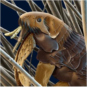
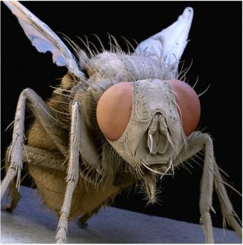
11 Fig. 8. Images of a beetle and an ant head. Fig. 9. Images of a head of a maggot, cat flea and household fly.
12 Resolution The numerical aperture NA of a microscope objective is a measure of its ability to gather light and resolve fine specimen detail at a fixed object distance. Image-forming light waves pass through the specimen and enter the objective lens in an inverted cone as shown in figure (10). The angle is one-half the angular aperture (2 ) and is related to the numerical aperture NA (1) Numerical Aperture NA = n sin where n is the refractive index of the imaging medium between the front lens of the objective and the specimen cover glass, a value that ranges from 1.00 for air to 1.51 for specialized immersion oils. objective lens light cone 2 Fig. 10. Numerical aperture of a lens.
13 By examining the numerical aperture equation, it is apparent that refractive index is the limiting factor in achieving numerical apertures greater than 1.0. Therefore, in order to obtain higher working numerical apertures, the refractive index of the medium between the front lens of the objective and the specimen must be increased. Microscope objectives are now available that allow imaging in alternative media such as water (refractive index = 1.33), glycerin (refractive index = 1.47), and immersion oil (refractive index = 1.51). Most objectives in the magnification range between 60x and 100x (and higher) are designed for use with immersion oil. The resolution of a microscope objective is defined as the smallest distance between two points on a specimen that can still be distinguished as two separate entities. Resolution is a somewhat subjective value in microscopy because at high magnification, an image may appear un-sharp but still be resolved to the maximum ability of the objective. Numerical aperture determines the resolving power of an objective, but the total resolution of a microscope system is also dependent upon the numerical aperture of the substage condenser. The higher the numerical aperture of the total system, the better the resolution.
14 Correct alignment of the microscope optical system is also of paramount importance to ensure maximum resolution. The substage condenser must be matched to the objective with respect to numerical aperture and adjustment of the aperture iris diaphragm for accurate light cone formation. The wavelength spectrum of light used to image a specimen is also a determining factor in resolution. Shorter wavelengths are capable of resolving details to a greater degree than are the longer wavelengths. There are several equations that have been derived to express the relationship between numerical aperture, wavelength, and resolution: (2) resolution R = 0.61 λ / 2NA R NA R The smaller the value of R, the better the resolution and points closer together can be identified. It is well worth visiting the web site
15 VISUAL PHYSICS ONLINE If you have any feedback, comments, suggestions or corrections please Ian Cooper School of Physics University of Sydney
Education in Microscopy and Digital Imaging
 Contact Us Carl Zeiss Education in Microscopy and Digital Imaging ZEISS Home Products Solutions Support Online Shop ZEISS International ZEISS Campus Home Interactive Tutorials Basic Microscopy Spectral
Refraction, Lenses, and Prisms
 CHAPTER 16 14 SECTION Sound and Light Refraction, Lenses, and Prisms KEY IDEAS As you read this section, keep these questions in mind: What happens to light when it passes from one medium to another? How
Microscope anatomy, image formation and resolution
 Microscope anatomy, image formation and resolution Ian Dobbie Buy this book for your lab: D.B. Murphy, "Fundamentals of light microscopy and electronic imaging", ISBN 0-471-25391-X Visit these websites:
There is a range of distances over which objects will be in focus; this is called the depth of field of the lens. Objects closer or farther are
 Chapter 25 Optical Instruments Some Topics in Chapter 25 Cameras The Human Eye; Corrective Lenses Magnifying Glass Telescopes Compound Microscope Aberrations of Lenses and Mirrors Limits of Resolution
Physics 11. Unit 8 Geometric Optics Part 2
 Physics 11 Unit 8 Geometric Optics Part 2 (c) Refraction (i) Introduction: Snell s law Like water waves, when light is traveling from one medium to another, not only does its wavelength, and in turn the
Life Science Chapter 2 Study Guide
 Key concepts and definitions Waves and the Electromagnetic Spectrum Wave Energy Medium Mechanical waves Amplitude Wavelength Frequency Speed Properties of Waves (pages 40-41) Trough Crest Hertz Electromagnetic
Reflection! Reflection and Virtual Image!
 1/30/14 Reflection - wave hits non-absorptive surface surface of a smooth water pool - incident vs. reflected wave law of reflection - concept for all electromagnetic waves - wave theory: reflected back
INTRODUCTION THIN LENSES. Introduction. given by the paraxial refraction equation derived last lecture: Thin lenses (19.1) = 1. Double-lens systems
 = 1. Double-lens systems") Chapter 9 OPTICAL INSTRUMENTS Introduction Thin lenses Double-lens systems Aberrations Camera Human eye Compound microscope Summary INTRODUCTION Knowledge of geometrical optics, diffraction and interference,
Chapter 9 OPTICAL INSTRUMENTS Introduction Thin lenses Double-lens systems Aberrations Camera Human eye Compound microscope Summary INTRODUCTION Knowledge of geometrical optics, diffraction and interference,
PHYSICS. Chapter 35 Lecture FOR SCIENTISTS AND ENGINEERS A STRATEGIC APPROACH 4/E RANDALL D. KNIGHT
 PHYSICS FOR SCIENTISTS AND ENGINEERS A STRATEGIC APPROACH 4/E Chapter 35 Lecture RANDALL D. KNIGHT Chapter 35 Optical Instruments IN THIS CHAPTER, you will learn about some common optical instruments and
OPTICAL SYSTEMS OBJECTIVES
 101 L7 OPTICAL SYSTEMS OBJECTIVES Aims Your aim here should be to acquire a working knowledge of the basic components of optical systems and understand their purpose, function and limitations in terms
Introduction to Light Microscopy. (Image: T. Wittman, Scripps)
") Introduction to Light Microscopy (Image: T. Wittman, Scripps) The Light Microscope Four centuries of history Vibrant current development One of the most widely used research tools A. Khodjakov et al. Major
Introduction to Light Microscopy (Image: T. Wittman, Scripps) The Light Microscope Four centuries of history Vibrant current development One of the most widely used research tools A. Khodjakov et al. Major
The Microscope. Packet #2. 10/17/2016 9:12:02 PM Ryan Barrow 2012
 1 The Microscope Packet #2 10/17/2016 9:12:02 PM Ryan Barrow 2012 2 Historical Timeline 1609 Galileo Galilei develops a compound microscope with a convex and a concave les. 1665 Robert Hooke publishes
Chapter 25. Optical Instruments
 Chapter 25 Optical Instruments Optical Instruments Analysis generally involves the laws of reflection and refraction Analysis uses the procedures of geometric optics To explain certain phenomena, the wave
Test Review # 8. Physics R: Form TR8.17A. Primary colors of light
 Physics R: Form TR8.17A TEST 8 REVIEW Name Date Period Test Review # 8 Light and Color. Color comes from light, an electromagnetic wave that travels in straight lines in all directions from a light source
Light Microscopy. Upon completion of this lecture, the student should be able to:
 Light Light microscopy is based on the interaction of light and tissue components and can be used to study tissue features. Upon completion of this lecture, the student should be able to: 1- Explain the
OPTICS DIVISION B. School/#: Names:
 OPTICS DIVISION B School/#: Names: Directions: Fill in your response for each question in the space provided. All questions are worth two points. Multiple Choice (2 points each question) 1. Which of the
CHAPTER TWO METALLOGRAPHY & MICROSCOPY
 CHAPTER TWO METALLOGRAPHY & MICROSCOPY 1. INTRODUCTION: Materials characterisation has two main aspects: Accurately measuring the physical, mechanical and chemical properties of materials Accurately measuring
Observing Microorganisms through a Microscope LIGHT MICROSCOPY: This type of microscope uses visible light to observe specimens. Compound Light Micros
 PHARMACEUTICAL MICROBIOLOGY JIGAR SHAH INSTITUTE OF PHARMACY NIRMA UNIVERSITY Observing Microorganisms through a Microscope LIGHT MICROSCOPY: This type of microscope uses visible light to observe specimens.
Applications of Optics
 Nicholas J. Giordano www.cengage.com/physics/giordano Chapter 26 Applications of Optics Marilyn Akins, PhD Broome Community College Applications of Optics Many devices are based on the principles of optics
Chapter 25 Optical Instruments
 Chapter 25 Optical Instruments Units of Chapter 25 Cameras, Film, and Digital The Human Eye; Corrective Lenses Magnifying Glass Telescopes Compound Microscope Aberrations of Lenses and Mirrors Limits of
 Microscopy http://www.microscopyu.com/articles/phasecontrast/phasemicroscopy.html http://micro.magnet.fsu.edu/primer/anatomy/anatomy.html 2005, Dr. Jack Ikeda & Dr. Gail Grabner 9 Nikon Labophot (Question
Chapter 29/30. Wave Fronts and Rays. Refraction of Sound. Dispersion in a Prism. Index of Refraction. Refraction and Lenses
 Chapter 29/30 Refraction and Lenses Refraction Refraction the bending of waves as they pass from one medium into another. Caused by a change in the average speed of light. Analogy A car that drives off
Reflection and Refraction of Light
 Reflection and Refraction of Light Physics 102 28 March 2002 Lecture 6 28 Mar 2002 Physics 102 Lecture 6 1 Light waves and light rays Last time we showed: Time varying B fields E fields B fields to create
PHYSICS FOR THE IB DIPLOMA CAMBRIDGE UNIVERSITY PRESS
 Option C Imaging C Introduction to imaging Learning objectives In this section we discuss the formation of images by lenses and mirrors. We will learn how to construct images graphically as well as algebraically.
Microscopy Techniques that make it easy to see things this small.
 Microscopy Techniques that make it easy to see things this small. What is a Microscope? An instrument for viewing objects that are too small to be seen easily by the naked eye. Dutch spectacle-makers Hans
Chapter 3 Op,cal Instrumenta,on
 Imaging by an Op,cal System Change in curvature of wavefronts by a thin lens Chapter 3 Op,cal Instrumenta,on 3-1 Stops, Pupils, and Windows 3-4 The Camera 3-5 Simple Magnifiers and Eyepieces 1. Magnifiers
30 Lenses. Lenses change the paths of light.
 Lenses change the paths of light. A light ray bends as it enters glass and bends again as it leaves. Light passing through glass of a certain shape can form an image that appears larger, smaller, closer,
MICROSCOPY MICROSCOPE TERMINOLOGY
 1 MICROSCOPY Most of the microorganisms that we talk about in this class are too small to be seen with the naked eye. The instruments we will use to visualize these microbes are microscopes. The laboratory
MICROSCOPE LAB. Resolving Power How well specimen detail is preserved during the magnifying process.
 AP BIOLOGY Cells ACTIVITY #2 MICROSCOPE LAB OBJECTIVES 1. Demonstrate proper care and use of a compound microscope. 2. Identify the parts of the microscope and describe the function of each part. 3. Compare
Chapter 3 Op+cal Instrumenta+on
 Chapter 3 Op+cal Instrumenta+on 3-1 Stops, Pupils, and Windows 3-4 The Camera 3-5 Simple Magnifiers and Eyepieces 3-6 Microscopes 3-7 Telescopes Today (2011-09-22) 1. Magnifiers 2. Camera 3. Resolution
Observing Microorganisms through a Microscope
 2016/2/19 PowerPoint Lecture Presentations prepared by Bradley W. Christian, McLennan Community College CHAPTER 3 Observing Microorganisms through a Microscope 1 Figure 3.2 Microscopes and Magnification.
25 cm. 60 cm. 50 cm. 40 cm.
 Geometrical Optics 7. The image formed by a plane mirror is: (a) Real. (b) Virtual. (c) Erect and of equal size. (d) Laterally inverted. (e) B, c, and d. (f) A, b and c. 8. A real image is that: (a) Which
Figure 3.4 Approximate size of various types of cells. ~10 um. Red Blood Cells = mm 1500 um. Width of penny Pearson Education, Inc.
 Figure 3.4 Approximate size of various types of cells. ~10 um Red Blood Cells 1.5mm 1500 um Width of penny = 1500 Figure 4.3 The limits of resolution (and some representative objects within those ranges)
The microscope is useful in making observations and collecting data in scientific experiments. Microscopy involves three basic concepts:
 AP BIOLOGY Chapter 6 NAME DATE Block MICROSCOPE LAB PART I: COMPOUND MICROSCOPE OBJECTIVES: After completing this exercise you should be able to: Demonstrate proper care and use of a compound microscope.
Applied Optics. , Physics Department (Room #36-401) , ,
 , ,") Applied Optics Professor, Physics Department (Room #36-401) 2290-0923, 019-539-0923, shsong@hanyang.ac.kr Office Hours Mondays 15:00-16:30, Wednesdays 15:00-16:30 TA (Ph.D. student, Room #36-415) 2290-0921,
Applied Optics Professor, Physics Department (Room #36-401) 2290-0923, 019-539-0923, shsong@hanyang.ac.kr Office Hours Mondays 15:00-16:30, Wednesdays 15:00-16:30 TA (Ph.D. student, Room #36-415) 2290-0921,
microscopy A great online resource Molecular Expressions, a Microscope Primer Partha Roy
 Fundamentals of optical microscopy A great online resource Molecular Expressions, a Microscope Primer http://micro.magnet.fsu.edu/primer/index.html Partha Roy 1 Why microscopy Topics Functions of a microscope
SUBJECT: PHYSICS. Use and Succeed.
 SUBJECT: PHYSICS I hope this collection of questions will help to test your preparation level and useful to recall the concepts in different areas of all the chapters. Use and Succeed. Navaneethakrishnan.V
Chapter 2 - Geometric Optics
 David J. Starling Penn State Hazleton PHYS 214 The human eye is a visual system that collects light and forms an image on the retina. The human eye is a visual system that collects light and forms an image
Instructional Resources/Materials: Light vocabulary cards printed (class set) Enough for each student (See card sort below)
 Enough for each student (See card sort below)") Grade Level/Course: Grade 7 Life Science Lesson/Unit Plan Name: Light Card Sort Rationale/Lesson Abstract: Light vocabulary building, students identify and share vocabulary meaning. Timeframe: 10 to 20
Grade Level/Course: Grade 7 Life Science Lesson/Unit Plan Name: Light Card Sort Rationale/Lesson Abstract: Light vocabulary building, students identify and share vocabulary meaning. Timeframe: 10 to 20
LlIGHT REVIEW PART 2 DOWNLOAD, PRINT and submit for 100 points
 WRITE ON SCANTRON WITH NUMBER 2 PENCIL DO NOT WRITE ON THIS TEST LlIGHT REVIEW PART 2 DOWNLOAD, PRINT and submit for 100 points Multiple Choice Identify the choice that best completes the statement or
Microscope. Dr. Leena Barhate Department of Microbiology M.J.College, Jalgaon
 Microscope Dr. Leena Barhate Department of Microbiology M.J.College, Jalgaon Acknowledgement http://www.cerebromente.org.br/n17/histor y/neurons1_i.htm Google Images http://science.howstuffworks.com/lightmicroscope1.htm
Section 1: Sound. Sound and Light Section 1
 Sound and Light Section 1 Section 1: Sound Preview Key Ideas Bellringer Properties of Sound Sound Intensity and Decibel Level Musical Instruments Hearing and the Ear The Ear Ultrasound and Sonar Sound
Lecture Outline Chapter 27. Physics, 4 th Edition James S. Walker. Copyright 2010 Pearson Education, Inc.
 Lecture Outline Chapter 27 Physics, 4 th Edition James S. Walker Chapter 27 Optical Instruments Units of Chapter 27 The Human Eye and the Camera Lenses in Combination and Corrective Optics The Magnifying
Microscopy. Matti Hotokka Department of Physical Chemistry Åbo Akademi University
 Microscopy Matti Hotokka Department of Physical Chemistry Åbo Akademi University What s coming Anatomy of a microscope Modes of illumination Practicalities Special applications Basic microscope Ocular
Lecture 8. Lecture 8. r 1
 Lecture 8 Achromat Design Design starts with desired Next choose your glass materials, i.e. Find P D P D, then get f D P D K K Choose radii (still some freedom left in choice of radii for minimization
Tissue Preparation ORGANISM IMAGE TISSUE PREPARATION. 1) Fixation: halts cell metabolism, preserves cell/tissue structure
 Fixation: halts cell metabolism, preserves cell/tissue structure") Lab starts this week! ANNOUNCEMENTS - Tuesday or Wednesday 1:25 ISB 264 - Read Lab 1: Microscopy and Imaging (see Web Page) - Getting started on Lab Group project - Organ for investigation - Lab project
Lab starts this week! ANNOUNCEMENTS - Tuesday or Wednesday 1:25 ISB 264 - Read Lab 1: Microscopy and Imaging (see Web Page) - Getting started on Lab Group project - Organ for investigation - Lab project
[ Summary. 3i = 1* 6i = 4J;
 the projections at angle 2. We calculate the difference between the measured projections at angle 2 (6 and 14) and the projections based on the previous esti mate (top row: 2>\ + 6\ = 10; same for bottom
Biology 29 Cell Structure and Function Spring, 2009 Springer LABORATORY 1: THE LIGHT MICROSCOPE
 Biology 29 Cell Structure and Function Spring, 2009 Springer LABORATORY 1: THE LIGHT MICROSCOPE Prior to lab: 1) Read these instructions (p 1-6) 2) Go through the online tutorial, the microscopy pre-lab
General Physics II. Ray Optics
 General Physics II Ray Optics 1 Dispersion White light is a combination of all the wavelengths of the visible part of the electromagnetic spectrum. Red light has the longest wavelengths and violet light
GIST OF THE UNIT BASED ON DIFFERENT CONCEPTS IN THE UNIT (BRIEFLY AS POINT WISE). RAY OPTICS
. RAY OPTICS") 209 GIST OF THE UNIT BASED ON DIFFERENT CONCEPTS IN THE UNIT (BRIEFLY AS POINT WISE). RAY OPTICS Reflection of light: - The bouncing of light back into the same medium from a surface is called reflection
209 GIST OF THE UNIT BASED ON DIFFERENT CONCEPTS IN THE UNIT (BRIEFLY AS POINT WISE). RAY OPTICS Reflection of light: - The bouncing of light back into the same medium from a surface is called reflection
Microscopy: Fundamental Principles and Practical Approaches
 Microscopy: Fundamental Principles and Practical Approaches Simon Atkinson Online Resource: http://micro.magnet.fsu.edu/primer/index.html Book: Murphy, D.B. Fundamentals of Light Microscopy and Electronic
Katarina Logg, Kristofer Bodvard, Mikael Käll. Dept. of Applied Physics. 12 September Optical Microscopy. Supervisor s signature:...
 Katarina Logg, Kristofer Bodvard, Mikael Käll Dept. of Applied Physics 12 September 2007 O1 Optical Microscopy Name:.. Date:... Supervisor s signature:... Introduction Over the past decades, the number
Chapter 2 The Study of Microbial Structure: Microscopy and Specimen Preparation
 Chapter 2 The Study of Microbial Structure: Microscopy and Specimen Preparation 1 Lenses and the Bending of Light light is refracted (bent) when passing from one medium to another refractive index a measure
The Compound Microscope. Brightfield: Köhler Illumination
 Outline History of Microscopy The Magnifying Glass The Compound Microscope Brightfield: Köhler Illumination Microscopy µικροσ (mikros): small σκοπειν (skopein): to observe History of Microscopy Well :
Scale. A Microscope s job in life. The Light Microscope. The Compound Microscope 9/24/12. Compound Microscope Anatomy
 The Study of Microbial Structure: Microscopy and Specimen Preparation Scale A Microscope s job in life 1.Magnify 2. Resolve ability to separate or distinguish between two points 3. Contrast How much or
Name. Light Chapter Summary Cont d. Refraction
 Page 1 of 17 Physics Week 12(Sem. 2) Name Light Chapter Summary Cont d with a smaller index of refraction to a material with a larger index of refraction, the light refracts towards the normal line. Also,
Chapter 23 Study Questions Name: Class:
 Chapter 23 Study Questions Name: Class: Multiple Choice Identify the letter of the choice that best completes the statement or answers the question. 1. When you look at yourself in a plane mirror, you
sclera pupil What happens to light that enters the eye?
 Human Vision Textbook pages 202 215 Before You Read Some people can see things clearly from a great distance. Other people can see things clearly only when they are nearby. Why might this be? Write your
Burton's Microbiology for the Health Sciences
 Burton's Microbiology for the Health Sciences Chapter 2. Viewing the Microbial World Chapter 2 Outline Introduction Using the metric system to express the sizes of microbes Microscopes Simple microscopes
Exam 4. Name: Class: Date: Multiple Choice Identify the choice that best completes the statement or answers the question.
 Name: Class: Date: Exam 4 Multiple Choice Identify the choice that best completes the statement or answers the question. 1. Mirages are a result of which physical phenomena a. interference c. reflection
EE119 Introduction to Optical Engineering Spring 2003 Final Exam. Name:
 EE119 Introduction to Optical Engineering Spring 2003 Final Exam Name: SID: CLOSED BOOK. THREE 8 1/2 X 11 SHEETS OF NOTES, AND SCIENTIFIC POCKET CALCULATOR PERMITTED. TIME ALLOTTED: 180 MINUTES Fundamental
Test Review # 9. Physics R: Form TR9.15A. Primary colors of light
 Physics R: Form TR9.15A TEST 9 REVIEW Name Date Period Test Review # 9 Light and Color. Color comes from light, an electromagnetic wave that travels in straight lines in all directions from a light source
Basics of Light Microscopy and Metallography
 ENGR45: Introduction to Materials Spring 2012 Laboratory 8 Basics of Light Microscopy and Metallography In this exercise you will: gain familiarity with the proper use of a research-grade light microscope
STRUCTURE OF THE MICROSCOPE
 STRUCTURE OF THE MICROSCOPE Use the word list to label the microscope below: Light Source Coarse adjustment knob Diaphragm Stage Clips Objectives Fine Adjustment Knob Base Stage Stage Clips Arm Revolving
used to diagnose and treat medical conditions. State the precautions necessary when X ray machines and CT scanners are used.
 Page 1 State the properties of X rays. Describe how X rays can be used to diagnose and treat medical conditions. State the precautions necessary when X ray machines and CT scanners are used. What is meant
Very short introduction to light microscopy and digital imaging
 Very short introduction to light microscopy and digital imaging Hernan G. Garcia August 1, 2005 1 Light Microscopy Basics In this section we will briefly describe the basic principles of operation and
Option G 2: Lenses. The diagram below shows the image of a square grid as produced by a lens that does not cause spherical aberration.
 Name: Date: Option G 2: Lenses 1. This question is about spherical aberration. The diagram below shows the image of a square grid as produced by a lens that does not cause spherical aberration. In the
OPAC 202 Optical Design and Instrumentation. Topic 3 Review Of Geometrical and Wave Optics. Department of
 OPAC 202 Optical Design and Instrumentation Topic 3 Review Of Geometrical and Wave Optics Department of http://www.gantep.edu.tr/~bingul/opac202 Optical & Acustical Engineering Gaziantep University Feb
Physics 208 Spring 2008 Lab 2: Lenses and the eye
 Name Section Physics 208 Spring 2008 Lab 2: Lenses and the eye Your TA will use this sheet to score your lab. It is to be turned in at the end of lab. You must use complete sentences and clearly explain
Optical Systems. The normal eye
 Optical Systems The normal eye The ciliary muscles can adjust the shape of the lens of the human eye. As the eye attempts to see objects at different distances, the muscles will adjust the focal length
The light microscope
 What is a microscope? The microscope is an essential tool in modern biology. It allows us to view structural details of organs, tissue, and cells not visible to the naked eye. The microscope should always
Marine Invertebrate Zoology Microscope Introduction
 Marine Invertebrate Zoology Microscope Introduction Introduction A laboratory tool that has become almost synonymous with biology is the microscope. As an extension of your eyes, the microscope is one
Geometrical Optics Optical systems
 Phys 322 Lecture 16 Chapter 5 Geometrical Optics Optical systems Magnifying glass Purpose: enlarge a nearby object by increasing its image size on retina Requirements: Image should not be inverted Image
ECEN 4606, UNDERGRADUATE OPTICS LAB
 ECEN 4606, UNDERGRADUATE OPTICS LAB Lab 2: Imaging 1 the Telescope Original Version: Prof. McLeod SUMMARY: In this lab you will become familiar with the use of one or more lenses to create images of distant
Chapter 36. Image Formation
 Chapter 36 Image Formation Image of Formation Images can result when light rays encounter flat or curved surfaces between two media. Images can be formed either by reflection or refraction due to these
LOS 1 LASER OPTICS SET
 LOS 1 LASER OPTICS SET Contents 1 Introduction 3 2 Light interference 5 2.1 Light interference on a thin glass plate 6 2.2 Michelson s interferometer 7 3 Light diffraction 13 3.1 Light diffraction on a
Systems Biology. Optical Train, Köhler Illumination
 McGill University Life Sciences Complex Imaging Facility Systems Biology Microscopy Workshop Tuesday December 7 th, 2010 Simple Lenses, Transmitted Light Optical Train, Köhler Illumination What Does a
Chapter Ray and Wave Optics
 109 Chapter Ray and Wave Optics 1. An astronomical telescope has a large aperture to [2002] reduce spherical aberration have high resolution increase span of observation have low dispersion. 2. If two
Ch 24. Geometric Optics
 text concept Ch 24. Geometric Optics Fig. 24 3 A point source of light P and its image P, in a plane mirror. Angle of incidence =angle of reflection. text. Fig. 24 4 The blue dashed line through object
Physics 431 Final Exam Examples (3:00-5:00 pm 12/16/2009) TIME ALLOTTED: 120 MINUTES Name: Signature:
 TIME ALLOTTED: 120 MINUTES Name: Signature:") Physics 431 Final Exam Examples (3:00-5:00 pm 12/16/2009) TIME ALLOTTED: 120 MINUTES Name: PID: Signature: CLOSED BOOK. TWO 8 1/2 X 11 SHEET OF NOTES (double sided is allowed), AND SCIENTIFIC POCKET CALCULATOR
Physics 431 Final Exam Examples (3:00-5:00 pm 12/16/2009) TIME ALLOTTED: 120 MINUTES Name: PID: Signature: CLOSED BOOK. TWO 8 1/2 X 11 SHEET OF NOTES (double sided is allowed), AND SCIENTIFIC POCKET CALCULATOR
S200 Course LECTURE 1 TEM
 S200 Course LECTURE 1 TEM Development of Electron Microscopy 1897 Discovery of the electron (J.J. Thompson) 1924 Particle and wave theory (L. de Broglie) 1926 Electromagnetic Lens (H. Busch) 1932 Construction
Phy Ph s y 102 Lecture Lectur 21 Optical instruments 1
 Phys 102 Lecture 21 Optical instruments 1 Today we will... Learn how combinations of lenses form images Thin lens equation & magnification Learn about the compound microscope Eyepiece & objective Total
Light sources can be natural or artificial (man-made)
") Light The Sun is our major source of light Light sources can be natural or artificial (man-made) People and insects do not see the same type of light - people see visible light - insects see ultraviolet
Light The Sun is our major source of light Light sources can be natural or artificial (man-made) People and insects do not see the same type of light - people see visible light - insects see ultraviolet
CHAPTER 18 REFRACTION & LENSES
 Physics Approximate Timeline Students are expected to keep up with class work when absent. CHAPTER 18 REFRACTION & LENSES Day Plans for the day Assignments for the day 1 18.1 Refraction of Light o Snell
CCAM Microscope Objectives
 CCAM Microscope Objectives Things to consider when selecting an objective Magnification Numerical Aperture (NA) resolving power and light intensity of the objective Working Distance distance between the
Chapter 36: diffraction
 Chapter 36: diffraction Fresnel and Fraunhofer diffraction Diffraction from a single slit Intensity in the single slit pattern Multiple slits The Diffraction grating X-ray diffraction Circular apertures
EDULABZ INTERNATIONAL. Light ASSIGNMENT
 Light ASSIGNMENT 1. Fill in the blank spaces by choosing the correct words from the list given below : List : compound microscope, yellow, telescope, alter, vitreous humour, time, photographic camera,
Section A Conceptual and application type questions. 1 Which is more observable diffraction of light or sound? Justify. (1)
") INDIAN SCHOOL MUSCAT Department of Physics Class : XII Physics Worksheet - 6 (2017-2018) Chapter 9 and 10 : Ray Optics and wave Optics Section A Conceptual and application type questions 1 Which is more
INDIAN SCHOOL MUSCAT Department of Physics Class : XII Physics Worksheet - 6 (2017-2018) Chapter 9 and 10 : Ray Optics and wave Optics Section A Conceptual and application type questions 1 Which is more
GEOMETRICAL OPTICS Practical 1. Part I. BASIC ELEMENTS AND METHODS FOR CHARACTERIZATION OF OPTICAL SYSTEMS
 GEOMETRICAL OPTICS Practical 1. Part I. BASIC ELEMENTS AND METHODS FOR CHARACTERIZATION OF OPTICAL SYSTEMS Equipment and accessories: an optical bench with a scale, an incandescent lamp, matte, a set of
Lab 10: Lenses & Telescopes
 Physics 2020, Fall 2010 Lab 8 page 1 of 6 Circle your lab day and time. Your name: Mon Tue Wed Thu Fri TA name: 8-10 10-12 12-2 2-4 4-6 INTRODUCTION Lab 10: Lenses & Telescopes In this experiment, you
Microscopy. Danil Hammoudi.MD
 Microscopy Danil Hammoudi.MD Care and Handling of the Microscope: A microscope is a delicate piece of equipment and should be treated with care. Use two hands when carrying the microscope. Place one hand
Chapter 36. Image Formation
 Chapter 36 Image Formation Notation for Mirrors and Lenses The object distance is the distance from the object to the mirror or lens Denoted by p The image distance is the distance from the image to the
A BRIEF INTRODUCTION TO MICROSCOPY The two key properties of a microscope that allow you to see microbes are resolution and magnification.
 A BRIEF INTRODUCTION TO MICROSCOPY The two key properties of a microscope that allow you to see microbes are resolution and magnification. Magnification refers to the enlargement of the specimen when seen
Properties of optical instruments. Visual optical systems part 2: focal visual instruments (microscope type)
") Properties of optical instruments Visual optical systems part 2: focal visual instruments (microscope type) Examples of focal visual instruments magnifying glass Eyepieces Measuring microscopes from the
Properties of optical instruments Visual optical systems part 2: focal visual instruments (microscope type) Examples of focal visual instruments magnifying glass Eyepieces Measuring microscopes from the
Phys 102 Lecture 21 Optical instruments
 Phys 102 Lecture 21 Optical instruments 1 Today we will... Learn how combinations of lenses form images Thin lens equation & magnification Learn about the compound microscope Eyepiece & objective Total
HOLIDAY HOME WORK PHYSICS CLASS-12B AUTUMN BREAK 2018
 HOLIDAY HOME WK PHYSICS CLASS-12B AUTUMN BREAK 2018 NOTE: 1. THESE QUESTIONS ARE FROM PREVIOUS YEAR BOARD PAPERS FROM 2009-2018 CHAPTERS EMI,AC,OPTICS(BUT TRY TO SOLVE ONLY NON-REPEATED QUESTION) QUESTION
Types of lenses. Shown below are various types of lenses, both converging and diverging.
 Types of lenses Shown below are various types of lenses, both converging and diverging. Any lens that is thicker at its center than at its edges is a converging lens with positive f; and any lens that
Chapter 24 Geometrical Optics. Copyright 2010 Pearson Education, Inc.
 Chapter 24 Geometrical Optics Lenses convex (converging) concave (diverging) Mirrors Ray Tracing for Mirrors We use three principal rays in finding the image produced by a curved mirror. The parallel ray
General Physics II. Optical Instruments
 General Physics II Optical Instruments 1 The Thin-Lens Equation 2 The Thin-Lens Equation Using geometry, one can show that 1 1 1 s+ =. s' f The magnification of the lens is defined by For a thin lens,
Instructions. To run the slideshow:
 Instructions To run the slideshow: Click: view full screen mode, or press Ctrl +L. Left click advances one slide, right click returns to previous slide. To exit the slideshow press the Esc key. Optical