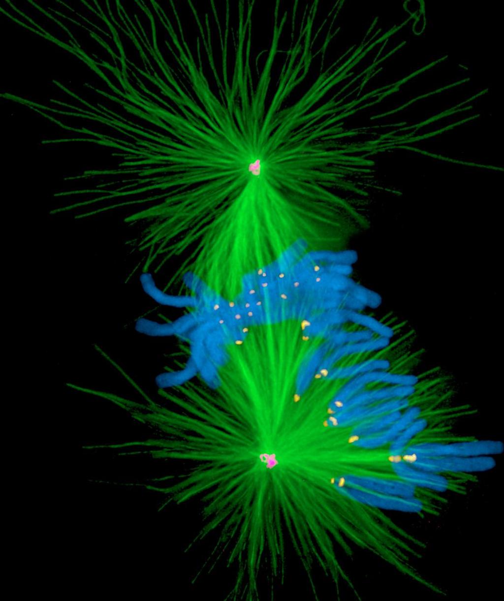
Introduction to Light Microscopy. (Image: T. Wittman, Scripps)
|
|
|
- Sheryl Lane
- 6 years ago
- Views:
Transcription

1 Introduction to Light Microscopy (Image: T. Wittman, Scripps)


2 The Light Microscope Four centuries of history Vibrant current development One of the most widely used research tools

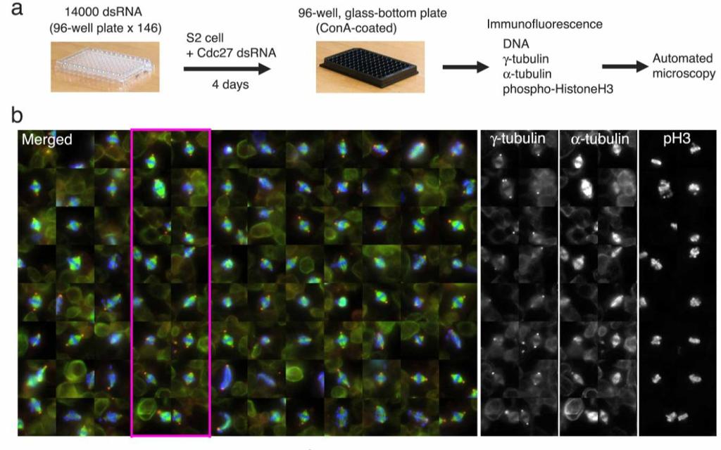
3 A. Khodjakov et al.
4 Major Imaging Functions of the Microscope Magnify Resolve features Generate Contrast Capture and Display Images

5 An Upright Epifluorescence Microscope

6 Waves vs. Photons vs. Rays Quantum wave-particle duality Rays: photon trajectories Rays: propagation direction of waves
7 Rays are perpendicular to wavefronts
8 Light travels more slowly in matter The speed ratio is the Index of Refraction, n v = c/n n = 1 n > 1 n = 1
9 Refractive Index Examples Vacuum 1 Air Water Cytoplasm ? Glycerol (anhydrous) Immersion oil Fused silica 1.46 Optical glasses Diamond Depends on wavelength and temperature
10 Refraction by an Interface Incident wave 1 r Reflected wave Refractive index n 1 = 1 Speed = c Refractive index n 2 Speed = c/n /n 2 Refracted wave Snell s law: n 1 Sin( 1 ) = n 2 Sin( 2 ) Mirror law: r = 1
11 Which Direction? n 1 n 2 > n 1 Refraction goes towards the normal in the higher-index medium
12 Lenses work by refraction Incident light focus Focal length f
13 Ray Tracing Rules of Thumb (for thin ideal lenses) Parallel rays converge at the focal plane Rays that cross in the focal plane end up parallel f f Rays through the lens center are unaffected
14 Imaging Object f Image d 1 d 2 L 1 L 2 The lens law: 1 L 1 1 L 2 1 f Magnification: M d 2 d 1 L 2 L 1
15 Finite vs. Infinite Conjugate Imaging Finite conjugate imaging (older objectives) Object f 0 Image >f 0 f 0 Infinite conjugate imaging (modern objectives). f 1 Object f 0 Image at infinity Need a tube lens Image f 0 f 0 (uncritical) f 1 Magnification: M f 1 f o
16 Back focal plane Back focal plane f 0 Object f 0 f 0 Rays that leave the object with the same angle meet in the objective s back focal plane
17 The Compound Microscope Exit pupil Eyepiece Primary or intermediate image plane Tube lens Objective Sample Back focal plane (pupil) Object plane
18 The Compound Microscope Final image Eye Exit pupil Eyepiece Intermediate image plane Tube lens Objective Sample Back focal plane (pupil) Object plane
19 The Compound Microscope Final image Eye Exit pupil Eyepiece Intermediate image plane Tube lens Back focal plane (pupil) Objective Sample Object plane
20 The Compound Microscope Final image Eye Exit pupil Eyepiece Intermediate image plane Tube lens Back focal plane (pupil) Objective Sample Object plane
21 The Compound Microscope Final image Eye Exit pupil Eyepiece Intermediate image plane Tube lens Objective Sample Back focal plane (pupil) Object plane
22 The Compound Microscope Camera Final image Projection Eyepiece Secondary pupil Intermediate image plane Tube lens Objective Sample Back focal plane (pupil) Object plane
 Diopter adjust (at least one must have this) Reticle or fitting for one Eye cups")
23 Eyepieces (Oculars) Features Magnification (10x typical) High eye point (exit pupil high enough to allow eyeglasses) Diopter adjust (at least one must have this) Reticle or fitting for one Eye cups
24 Trans-illumination Microscope Camera Final image plane Imaging path Projection Eyepiece Tube lens Secondary pupil plane Intermediate image plane Illumination path Objective Sample Condenser lens Aperture iris Field lens Field iris Collector Light source Back focal plane (pupil) Object plane (pupil plane) (image plane) (pupil plane) The aperture iris controls the range of illumination angles The field iris controls the illuminated field of view
25 Köhler Illumination Critical Illumination Sample Object plane Aperture iris (pupil plane) Field iris (image plane) Light source (pupil plane) Each light source point produces a parallel beam of light at the sample Uniform light intensity at the sample even if the light source is ugly (e.g. a filament) The source is imaged onto the sample Usable only if the light source is perfectly uniform

26 Conjugate Planes in A Research Microscope
27 How view the pupil planes? Two ways: Eyepiece telescope Bertrand lens
28 By far the most important part: the Objective Lens Each major manufacturer sells different categories of objectives. What are the important distinctions?

29 Working Distance In general, high NA lenses have short working distances However, extra-long working distance objectives do exist Some examples: 10x/0.3 WD = 15.2mm 20x/0.75 WD = 1.0mm 100x/1.4 WD = 0.13mm
30 The focal length of a lens depends on the refractive index Refractive index n f 1/(n-1) Focal length f
 Glass")
31 and the refractive index depends on the wavelength ( dispersion ) Glass types
32 Chromatic aberration Different colors get focused to different planes Not good


33 Dispersion vs. refractive index of different glass types Refractive index Abbe dispersion number (Higher dispersion )
34 Achromatic Lenses Use a weak negative flint glass element to compensate the dispersion of a positive crown glass element
35 Achromats and Apochromats Focal length error Wavelength Apochromat ( 3 glass types) Achromat (2 glass types) Simple lens
 Correction for other (i.e. monochromatic) aberrations also improves in the same order")
36 Correction classes of objectives Achromat (cheap) Fluor semi-apo (good correction, high UV transmission) Apochromat (best correction) Correction for other (i.e. monochromatic) aberrations also improves in the same order

37 Curvature of Field Focal plane Focal surface Tube lens objective sample Focal surface

38 Plan objectives Corrected for field curvature More complex design Needed for most photomicrography Plan-Apochromats have the highest performance (and highest complexity and price)
39 In phase Interference constructive interference + = Opposite phase + = destructive interference
40 Diffraction by a periodic structure (grating)
41 Diffraction by a periodic structure (grating) d In phase if: d Sin( ) = m for some integer m
42 Diffraction by an aperture drawn as waves Light spreads to new angles Larger aperture weaker diffraction
43 Diffraction by an aperture drawn as rays The pure, far-field diffraction pattern is formed at distance Tube lens or can be formed at a finite distance by a lens Objective pupil Intermediate image as happens in a microscope
44 The Airy Pattern = the far-field diffraction pattern from a round aperture Height of first ring 1.75% Airy disk diameter d = 2.44 f/d (for small angles d/f) d f

45 Objective Aperture and Resolution Tube lens Intermediate image plane Diffraction spot on image plane = Point Spread Function Sample Back focal plane aperture

46 Objective Aperture and Resolution Tube lens Intermediate image plane Diffraction spot on image plane = Point Spread Function Sample Back focal plane aperture

47 Objective Aperture and Resolution Tube lens Intermediate image plane Diffraction spot on image plane = Point Spread Function Sample Back focal plane aperture
48 Objective Aperture and Resolution Tube lens Intermediate image plane Diffraction spot on image plane (resolution) Sample Back focal plane aperture Image resolution improves with aperture size Numerical Aperture (NA) NA = n sin( ) where: = light gathering angle n = refractive index of sample
49 Numerical Aperture 100X / 0.95 NA = X / 0.20 NA = 11.5
 Glycerol immersion: n 1.45 (85%) max NA 1.35 (Leica) Water immersion: n 1.33 max NA 1.")
50 Immersion Objectives NA cannot exceed the lowest n between the sample and the objective lens NA >1 requires fluid immersion NA can approach the index of the immersion fluid Oil immersion: n max NA 1.4 ( for TIRF) Glycerol immersion: n 1.45 (85%) max NA 1.35 (Leica) Water immersion: n 1.33 max NA 1.2
51 Resolution Ernst Abbe s argument (1873) Consider a striped sample a diffraction grating Back focal plane Objective lens Sample Condenser d b Diffracted beams d sin(b) = Smaller d larger b Light source Consider first a point light source If b >, only one spot makes it through no interference no image formed Resolution (smallest resolvable d): dmin = sample/sin( ) = /n sin( ) = /NA
52 (Abbe s argument, continued) Now consider oblique illumination (an off-axis source point): One spot hopelessly lost, but two spots get through interference image formed! d bout bin d [sin(bin) + sin(bout) ] = Two spots get through if bout < and bin <. Resolution (smallest resolvable d) with incoherent illumination (all possible illumination directions): dmin = /(NAobj + NAcondenser ) /2 NA if NAcondenser NAobj ( Filling the back focal plane )
53 Aperture, Resolution & Contrast Can adjust the condenser NA with the aperture iris Imaging path Intermed. image Tube lens Illumination path Back aperture Objective Sample Condenser lens Aperture iris Field lens Field iris Collector Light source Q: Don t we always want it full open?? A: No Why? Tradeoff: resolution vs. contrast


54 NA and Resolution High NA Objective Low NA Objective
55 Alternate Definitions of Resolution As the Full Width at Half Max (FWHM) of the PSF FWHM /NA As the diameter of the Airy disk (first dark ring of the PSF) = Rayleigh criterion (Probably most common definition) Airy disk radius 0.61 /NA
56 Objective Types Plan or not Field flatness Basic properties Magnification Numerical Aperture (NA) Infinite or finite conjugate Cover slip thickness if any Immersion fluid if any Correction class Achromat Fluor Apochromat Phase rings for phase contrast Positive or negative Diameter of ring (number) Special Properties Strain free for Polarization or DIC Features Correction collar for spherical aberration Iris Spring-loaded front end Lockable front end
57 micro.magnet.fsu.edu Further reading Douglas B. Murphy Fundamentals of Light Microscopy and Electronic Imaging James Pawley, Ed. Handbook of Biological Confocal Microscopy, 3rd ed. Ron Vale / Mats Gustafsson Acknowledgements
Reflection! Reflection and Virtual Image!
 1/30/14 Reflection - wave hits non-absorptive surface surface of a smooth water pool - incident vs. reflected wave law of reflection - concept for all electromagnetic waves - wave theory: reflected back
Microscope anatomy, image formation and resolution
 Microscope anatomy, image formation and resolution Ian Dobbie Buy this book for your lab: D.B. Murphy, "Fundamentals of light microscopy and electronic imaging", ISBN 0-471-25391-X Visit these websites:
VISUAL PHYSICS ONLINE DEPTH STUDY: ELECTRON MICROSCOPES
 VISUAL PHYSICS ONLINE DEPTH STUDY: ELECTRON MICROSCOPES Shortly after the experimental confirmation of the wave properties of the electron, it was suggested that the electron could be used to examine objects
Katarina Logg, Kristofer Bodvard, Mikael Käll. Dept. of Applied Physics. 12 September Optical Microscopy. Supervisor s signature:...
 Katarina Logg, Kristofer Bodvard, Mikael Käll Dept. of Applied Physics 12 September 2007 O1 Optical Microscopy Name:.. Date:... Supervisor s signature:... Introduction Over the past decades, the number
Applied Optics. , Physics Department (Room #36-401) , ,
 , ,") Applied Optics Professor, Physics Department (Room #36-401) 2290-0923, 019-539-0923, shsong@hanyang.ac.kr Office Hours Mondays 15:00-16:30, Wednesdays 15:00-16:30 TA (Ph.D. student, Room #36-415) 2290-0921,
Applied Optics Professor, Physics Department (Room #36-401) 2290-0923, 019-539-0923, shsong@hanyang.ac.kr Office Hours Mondays 15:00-16:30, Wednesdays 15:00-16:30 TA (Ph.D. student, Room #36-415) 2290-0921,
BASICS IN BIOIMAGING AND OPTICS PLATFORM EPFL SV PTBIOP LIGHT MICROSCOPY
 BASICS IN LIGHT MICROSCOPY OVERVIEW 1. Motivation 2. Basic in optics 3. How microscope works 4. Illumination and resolution 5. Microscope optics 6. Contrasting methods -2- MOTIVATION Why do we need microscopy?
25 cm. 60 cm. 50 cm. 40 cm.
 Geometrical Optics 7. The image formed by a plane mirror is: (a) Real. (b) Virtual. (c) Erect and of equal size. (d) Laterally inverted. (e) B, c, and d. (f) A, b and c. 8. A real image is that: (a) Which
INTRODUCTION THIN LENSES. Introduction. given by the paraxial refraction equation derived last lecture: Thin lenses (19.1) = 1. Double-lens systems
 = 1. Double-lens systems") Chapter 9 OPTICAL INSTRUMENTS Introduction Thin lenses Double-lens systems Aberrations Camera Human eye Compound microscope Summary INTRODUCTION Knowledge of geometrical optics, diffraction and interference,
Chapter 9 OPTICAL INSTRUMENTS Introduction Thin lenses Double-lens systems Aberrations Camera Human eye Compound microscope Summary INTRODUCTION Knowledge of geometrical optics, diffraction and interference,
Microscopy: Fundamental Principles and Practical Approaches
 Microscopy: Fundamental Principles and Practical Approaches Simon Atkinson Online Resource: http://micro.magnet.fsu.edu/primer/index.html Book: Murphy, D.B. Fundamentals of Light Microscopy and Electronic
Systems Biology. Optical Train, Köhler Illumination
 McGill University Life Sciences Complex Imaging Facility Systems Biology Microscopy Workshop Tuesday December 7 th, 2010 Simple Lenses, Transmitted Light Optical Train, Köhler Illumination What Does a
BASICS IN LIGHT MICROSCOPY
 BASICS IN LIGHT MICROSCOPY INTERNAL COURSE 2015 26 TH JANUARY OVERVIEW Light microscopy Why do we need it? How does it work? What are its limitations? What do we need to consider? - 2 - HUMAN EYE Normal
Lecture 2: Geometrical Optics. Geometrical Approximation. Lenses. Mirrors. Optical Systems. Images and Pupils. Aberrations.
 Lecture 2: Geometrical Optics Outline 1 Geometrical Approximation 2 Lenses 3 Mirrors 4 Optical Systems 5 Images and Pupils 6 Aberrations Christoph U. Keller, Leiden Observatory, keller@strw.leidenuniv.nl
Education in Microscopy and Digital Imaging
 Contact Us Carl Zeiss Education in Microscopy and Digital Imaging ZEISS Home Products Solutions Support Online Shop ZEISS International ZEISS Campus Home Interactive Tutorials Basic Microscopy Spectral
Optical Design of. Microscopes. George H. Seward. Tutorial Texts in Optical Engineering Volume TT88. SPIE PRESS Bellingham, Washington USA
 Optical Design of Microscopes George H. Seward Tutorial Texts in Optical Engineering Volume TT88 SPIE PRESS Bellingham, Washington USA Preface xiii Chapter 1 Optical Design Concepts /1 1.1 A Value Proposition
Properties of optical instruments. Visual optical systems part 2: focal visual instruments (microscope type)
") Properties of optical instruments Visual optical systems part 2: focal visual instruments (microscope type) Examples of focal visual instruments magnifying glass Eyepieces Measuring microscopes from the
Properties of optical instruments Visual optical systems part 2: focal visual instruments (microscope type) Examples of focal visual instruments magnifying glass Eyepieces Measuring microscopes from the
Chapter 29/30. Wave Fronts and Rays. Refraction of Sound. Dispersion in a Prism. Index of Refraction. Refraction and Lenses
 Chapter 29/30 Refraction and Lenses Refraction Refraction the bending of waves as they pass from one medium into another. Caused by a change in the average speed of light. Analogy A car that drives off
SUBJECT: PHYSICS. Use and Succeed.
 SUBJECT: PHYSICS I hope this collection of questions will help to test your preparation level and useful to recall the concepts in different areas of all the chapters. Use and Succeed. Navaneethakrishnan.V
Lecture 2: Geometrical Optics. Geometrical Approximation. Lenses. Mirrors. Optical Systems. Images and Pupils. Aberrations.
 Lecture 2: Geometrical Optics Outline 1 Geometrical Approximation 2 Lenses 3 Mirrors 4 Optical Systems 5 Images and Pupils 6 Aberrations Christoph U. Keller, Leiden Observatory, keller@strw.leidenuniv.nl
microscopy A great online resource Molecular Expressions, a Microscope Primer Partha Roy
 Fundamentals of optical microscopy A great online resource Molecular Expressions, a Microscope Primer http://micro.magnet.fsu.edu/primer/index.html Partha Roy 1 Why microscopy Topics Functions of a microscope
BIOIMAGING AND OPTICS PLATFORM EPFL SV PTBIOP BASICS IN LIGHT MICROSCOPY
 BASICS IN LIGHT MICROSCOPY INTERNAL COURSE 2014 13 TH JANUARY OVERVIEW 1. Motivation 2. Basic in optics 3. How microscope works 4. Illumination and resolution 5. Microscope optics 6. Contrasting methods
Chapter 25 Optical Instruments
 Chapter 25 Optical Instruments Units of Chapter 25 Cameras, Film, and Digital The Human Eye; Corrective Lenses Magnifying Glass Telescopes Compound Microscope Aberrations of Lenses and Mirrors Limits of
There is a range of distances over which objects will be in focus; this is called the depth of field of the lens. Objects closer or farther are
 Chapter 25 Optical Instruments Some Topics in Chapter 25 Cameras The Human Eye; Corrective Lenses Magnifying Glass Telescopes Compound Microscope Aberrations of Lenses and Mirrors Limits of Resolution
CCAM s Selection of. Zeiss Microscope Objectives
 CCAM s Selection of Zeiss Microscope Objectives 1. Magnification Image scale 2. Resolution The minimum separation distance between two points that are clearly resolved. The resolution of an objective is
Chapter 25. Optical Instruments
 Chapter 25 Optical Instruments Optical Instruments Analysis generally involves the laws of reflection and refraction Analysis uses the procedures of geometric optics To explain certain phenomena, the wave
Opti 415/515. Introduction to Optical Systems. Copyright 2009, William P. Kuhn
 Opti 415/515 Introduction to Optical Systems 1 Optical Systems Manipulate light to form an image on a detector. Point source microscope Hubble telescope (NASA) 2 Fundamental System Requirements Application
Physics 431 Final Exam Examples (3:00-5:00 pm 12/16/2009) TIME ALLOTTED: 120 MINUTES Name: Signature:
 TIME ALLOTTED: 120 MINUTES Name: Signature:") Physics 431 Final Exam Examples (3:00-5:00 pm 12/16/2009) TIME ALLOTTED: 120 MINUTES Name: PID: Signature: CLOSED BOOK. TWO 8 1/2 X 11 SHEET OF NOTES (double sided is allowed), AND SCIENTIFIC POCKET CALCULATOR
Physics 431 Final Exam Examples (3:00-5:00 pm 12/16/2009) TIME ALLOTTED: 120 MINUTES Name: PID: Signature: CLOSED BOOK. TWO 8 1/2 X 11 SHEET OF NOTES (double sided is allowed), AND SCIENTIFIC POCKET CALCULATOR
CCAM Microscope Objectives
 CCAM Microscope Objectives Things to consider when selecting an objective Magnification Numerical Aperture (NA) resolving power and light intensity of the objective Working Distance distance between the
Overview of the Microscope Objective
 Overview of the Microscope Objective Item Type text; Electronic Thesis Authors Niu, Ruijuan Publisher The University of Arizona. Rights Copyright is held by the author. Digital access to this material
Lecture 23 MNS 102: Techniques for Materials and Nano Sciences
 Lecture 23 MNS 102: Techniques for Materials and Nano Sciences Reference: #1 C. R. Brundle, C. A. Evans, S. Wilson, "Encyclopedia of Materials Characterization", Butterworth-Heinemann, Toronto (1992),
The Nature of Light. Light and Energy
 The Nature of Light Light and Energy - dependent on energy from the sun, directly and indirectly - solar energy intimately associated with existence of life -light absorption: dissipate as heat emitted
Very short introduction to light microscopy and digital imaging
 Very short introduction to light microscopy and digital imaging Hernan G. Garcia August 1, 2005 1 Light Microscopy Basics In this section we will briefly describe the basic principles of operation and
CHAPTER 18 REFRACTION & LENSES
 Physics Approximate Timeline Students are expected to keep up with class work when absent. CHAPTER 18 REFRACTION & LENSES Day Plans for the day Assignments for the day 1 18.1 Refraction of Light o Snell
Imaging Introduction. September 24, 2010
 Imaging Introduction September 24, 2010 What is a microscope? Merriam-Webster: an optical instrument consisting of a lens or combination of lenses for making enlarged images of minute objects; especially:
Phys 102 Lecture 21 Optical instruments
 Phys 102 Lecture 21 Optical instruments 1 Today we will... Learn how combinations of lenses form images Thin lens equation & magnification Learn about the compound microscope Eyepiece & objective Total
OPTICS DIVISION B. School/#: Names:
 OPTICS DIVISION B School/#: Names: Directions: Fill in your response for each question in the space provided. All questions are worth two points. Multiple Choice (2 points each question) 1. Which of the
Name. Light Chapter Summary Cont d. Refraction
 Page 1 of 17 Physics Week 12(Sem. 2) Name Light Chapter Summary Cont d with a smaller index of refraction to a material with a larger index of refraction, the light refracts towards the normal line. Also,
Biomedical Imaging 生物醫學影像學
 Biomedical Imaging 生物醫學影像學 楊自森助理教授 牙體技術學系 2013/02/24 tsyang@tmu.edu.tw 1 Course Outline 1. Course Introduction 2. Basic Optics and Light Microscopes 3. Fluorescence/Confocal/TIRF Microscopes 4. FRET Techniques
Lecture Outline Chapter 27. Physics, 4 th Edition James S. Walker. Copyright 2010 Pearson Education, Inc.
 Lecture Outline Chapter 27 Physics, 4 th Edition James S. Walker Chapter 27 Optical Instruments Units of Chapter 27 The Human Eye and the Camera Lenses in Combination and Corrective Optics The Magnifying
Image Formation. Light from distant things. Geometrical optics. Pinhole camera. Chapter 36
 Light from distant things Chapter 36 We learn about a distant thing from the light it generates or redirects. The lenses in our eyes create images of objects our brains can process. This chapter concerns
OPTICAL SYSTEMS OBJECTIVES
 101 L7 OPTICAL SYSTEMS OBJECTIVES Aims Your aim here should be to acquire a working knowledge of the basic components of optical systems and understand their purpose, function and limitations in terms
OPTICAL PRINCIPLES OF MICROSCOPY. Interuniversity Course 28 December 2003 Aryeh M. Weiss Bar Ilan University
 OPTICAL PRINCIPLES OF MICROSCOPY Interuniversity Course 28 December 2003 Aryeh M. Weiss Bar Ilan University FOREWORD This slide set was originally presented at the ISM Workshop on Theoretical and Experimental
Phy Ph s y 102 Lecture Lectur 21 Optical instruments 1
 Phys 102 Lecture 21 Optical instruments 1 Today we will... Learn how combinations of lenses form images Thin lens equation & magnification Learn about the compound microscope Eyepiece & objective Total
Lecture 8. Lecture 8. r 1
 Lecture 8 Achromat Design Design starts with desired Next choose your glass materials, i.e. Find P D P D, then get f D P D K K Choose radii (still some freedom left in choice of radii for minimization
EE119 Introduction to Optical Engineering Spring 2003 Final Exam. Name:
 EE119 Introduction to Optical Engineering Spring 2003 Final Exam Name: SID: CLOSED BOOK. THREE 8 1/2 X 11 SHEETS OF NOTES, AND SCIENTIFIC POCKET CALCULATOR PERMITTED. TIME ALLOTTED: 180 MINUTES Fundamental
PHYSICS FOR THE IB DIPLOMA CAMBRIDGE UNIVERSITY PRESS
 Option C Imaging C Introduction to imaging Learning objectives In this section we discuss the formation of images by lenses and mirrors. We will learn how to construct images graphically as well as algebraically.
Basics of Light Microscopy and Metallography
 ENGR45: Introduction to Materials Spring 2012 Laboratory 8 Basics of Light Microscopy and Metallography In this exercise you will: gain familiarity with the proper use of a research-grade light microscope
Lecture 3: Geometrical Optics 1. Spherical Waves. From Waves to Rays. Lenses. Chromatic Aberrations. Mirrors. Outline
 Lecture 3: Geometrical Optics 1 Outline 1 Spherical Waves 2 From Waves to Rays 3 Lenses 4 Chromatic Aberrations 5 Mirrors Christoph U. Keller, Leiden Observatory, keller@strw.leidenuniv.nl Lecture 3: Geometrical
Chapter 2 - Geometric Optics
 David J. Starling Penn State Hazleton PHYS 214 The human eye is a visual system that collects light and forms an image on the retina. The human eye is a visual system that collects light and forms an image
CH. 23 Mirrors and Lenses HW# 6, 7, 9, 11, 13, 21, 25, 31, 33, 35
 CH. 23 Mirrors and Lenses HW# 6, 7, 9, 11, 13, 21, 25, 31, 33, 35 Mirrors Rays of light reflect off of mirrors, and where the reflected rays either intersect or appear to originate from, will be the location
University of Rochester Department of Physics and Astronomy Physics123, Spring Homework 5 - Solutions
 Problem 5. University of Rochester Department of Physics and Astronomy Physics23, Spring 202 Homework 5 - Solutions An optometrist finds that a farsighted person has a near point at 25 cm. a) If the eye
Physics 1C. Lecture 25B
 Physics 1C Lecture 25B "More than 50 years ago, Austrian researcher Ivo Kohler gave people goggles thats severely distorted their vision: The lenses turned the world upside down. After several weeks, subjects
PHYSICS. Chapter 35 Lecture FOR SCIENTISTS AND ENGINEERS A STRATEGIC APPROACH 4/E RANDALL D. KNIGHT
 PHYSICS FOR SCIENTISTS AND ENGINEERS A STRATEGIC APPROACH 4/E Chapter 35 Lecture RANDALL D. KNIGHT Chapter 35 Optical Instruments IN THIS CHAPTER, you will learn about some common optical instruments and
Microscopy. Lecture 2: Optical System of the Microscopy II Herbert Gross. Winter term
 Microscopy Lecture 2: Optical System of the Microscopy II 212-1-22 Herbert Gross Winter term 212 www.iap.uni-jena.de Preliminary time schedule 2 No Date Main subject Detailed topics Lecturer 1 15.1. Optical
Point Spread Function. Confocal Laser Scanning Microscopy. Confocal Aperture. Optical aberrations. Alternative Scanning Microscopy
 Bi177 Lecture 5 Adding the Third Dimension Wide-field Imaging Point Spread Function Deconvolution Confocal Laser Scanning Microscopy Confocal Aperture Optical aberrations Alternative Scanning Microscopy
Chapter Ray and Wave Optics
 109 Chapter Ray and Wave Optics 1. An astronomical telescope has a large aperture to [2002] reduce spherical aberration have high resolution increase span of observation have low dispersion. 2. If two
Section A Conceptual and application type questions. 1 Which is more observable diffraction of light or sound? Justify. (1)
") INDIAN SCHOOL MUSCAT Department of Physics Class : XII Physics Worksheet - 6 (2017-2018) Chapter 9 and 10 : Ray Optics and wave Optics Section A Conceptual and application type questions 1 Which is more
INDIAN SCHOOL MUSCAT Department of Physics Class : XII Physics Worksheet - 6 (2017-2018) Chapter 9 and 10 : Ray Optics and wave Optics Section A Conceptual and application type questions 1 Which is more
The Compound Microscope. Brightfield: Köhler Illumination
 Outline History of Microscopy The Magnifying Glass The Compound Microscope Brightfield: Köhler Illumination Microscopy µικροσ (mikros): small σκοπειν (skopein): to observe History of Microscopy Well :
Lecture 21. Physics 1202: Lecture 21 Today s Agenda
 Physics 1202: Lecture 21 Today s Agenda Announcements: Team problems today Team 14: Gregory Desautels, Benjamin Hallisey, Kyle Mcginnis Team 15: Austin Dion, Nicholas Gandza, Paul Macgillis-Falcon Homework
GEOMETRICAL OPTICS AND OPTICAL DESIGN
 GEOMETRICAL OPTICS AND OPTICAL DESIGN Pantazis Mouroulis Associate Professor Center for Imaging Science Rochester Institute of Technology John Macdonald Senior Lecturer Physics Department University of
Average: Standard Deviation: Max: 99 Min: 40
 1 st Midterm Exam Average: 83.1 Standard Deviation: 12.0 Max: 99 Min: 40 Please contact me to fix an appointment, if you took less than 65. Chapter 33 Lenses and Op/cal Instruments Units of Chapter 33
Chapter 3 Op,cal Instrumenta,on
 Imaging by an Op,cal System Change in curvature of wavefronts by a thin lens Chapter 3 Op,cal Instrumenta,on 3-1 Stops, Pupils, and Windows 3-4 The Camera 3-5 Simple Magnifiers and Eyepieces 1. Magnifiers
Chapter 26. The Refraction of Light: Lenses and Optical Instruments
 Chapter 26 The Refraction of Light: Lenses and Optical Instruments 26.1 The Index of Refraction Light travels through a vacuum at a speed c=3. 00 10 8 m/ s Light travels through materials at a speed less
Optical Components for Laser Applications. Günter Toesko - Laserseminar BLZ im Dezember
 Günter Toesko - Laserseminar BLZ im Dezember 2009 1 Aberrations An optical aberration is a distortion in the image formed by an optical system compared to the original. It can arise for a number of reasons
PHYS 202 OUTLINE FOR PART III LIGHT & OPTICS
 PHYS 202 OUTLINE FOR PART III LIGHT & OPTICS Electromagnetic Waves A. Electromagnetic waves S-23,24 1. speed of waves = 1/( o o ) ½ = 3 x 10 8 m/s = c 2. waves and frequency: the spectrum (a) radio red
OPAC 202 Optical Design and Instrumentation. Topic 3 Review Of Geometrical and Wave Optics. Department of
 OPAC 202 Optical Design and Instrumentation Topic 3 Review Of Geometrical and Wave Optics Department of http://www.gantep.edu.tr/~bingul/opac202 Optical & Acustical Engineering Gaziantep University Feb
CHAPTER TWO METALLOGRAPHY & MICROSCOPY
 CHAPTER TWO METALLOGRAPHY & MICROSCOPY 1. INTRODUCTION: Materials characterisation has two main aspects: Accurately measuring the physical, mechanical and chemical properties of materials Accurately measuring
Geometric Optics. Ray Model. assume light travels in straight line uses rays to understand and predict reflection & refraction
 Geometric Optics Ray Model assume light travels in straight line uses rays to understand and predict reflection & refraction General Physics 2 Geometric Optics 1 Reflection Law of reflection the angle
Mirrors, Lenses &Imaging Systems
 Mirrors, Lenses &Imaging Systems We describe the path of light as straight-line rays And light rays from a very distant point arrive parallel 145 Phys 24.1 Mirrors Standing away from a plane mirror shows
Chapter 3 Op+cal Instrumenta+on
 Chapter 3 Op+cal Instrumenta+on 3-1 Stops, Pupils, and Windows 3-4 The Camera 3-5 Simple Magnifiers and Eyepieces 3-6 Microscopes 3-7 Telescopes Today (2011-09-22) 1. Magnifiers 2. Camera 3. Resolution
Chapter 23. Light Geometric Optics
 Chapter 23. Light Geometric Optics There are 3 basic ways to gather light and focus it to make an image. Pinhole - Simple geometry Mirror - Reflection Lens - Refraction Pinhole Camera Image Formation (the
2/4/15. Brightfield Microscopy! It s all about Magnification..! or is it?!
 Brightfield Microscopy It s all about Magnification.. or is it? 1 What actually does go into chosing a microscope Choice depends on what you need the microscope to do. Do you want to magnify stained specimens?
Optical System Design
 Phys 531 Lecture 12 14 October 2004 Optical System Design Last time: Surveyed examples of optical systems Today, discuss system design Lens design = course of its own (not taught by me!) Try to give some
Converging and Diverging Surfaces. Lenses. Converging Surface
 Lenses Sandy Skoglund 2 Converging and Diverging s AIR Converging If the surface is convex, it is a converging surface in the sense that the parallel rays bend toward each other after passing through the
Heisenberg) relation applied to space and transverse wavevector
 relation applied to space and transverse wavevector") 2. Optical Microscopy 2.1 Principles A microscope is in principle nothing else than a simple lens system for magnifying small objects. The first lens, called the objective, has a short focal length (a
2. Optical Microscopy 2.1 Principles A microscope is in principle nothing else than a simple lens system for magnifying small objects. The first lens, called the objective, has a short focal length (a
Properties of optical instruments. Projection optical systems
 Properties of optical instruments Projection optical systems Instruments : optical systems designed for a specific function Projection systems: : real image (object real or at infinity) Examples: videoprojector,,
Cardinal Points of an Optical System--and Other Basic Facts
 Cardinal Points of an Optical System--and Other Basic Facts The fundamental feature of any optical system is the aperture stop. Thus, the most fundamental optical system is the pinhole camera. The image
Optical Systems: Pinhole Camera Pinhole camera: simple hole in a box: Called Camera Obscura Aristotle discussed, Al-Hazen analyzed in Book of Optics
 Optical Systems: Pinhole Camera Pinhole camera: simple hole in a box: Called Camera Obscura Aristotle discussed, Al-Hazen analyzed in Book of Optics 1011CE Restricts rays: acts as a single lens: inverts
Test Review # 8. Physics R: Form TR8.17A. Primary colors of light
 Physics R: Form TR8.17A TEST 8 REVIEW Name Date Period Test Review # 8 Light and Color. Color comes from light, an electromagnetic wave that travels in straight lines in all directions from a light source
Introduction. Geometrical Optics. Milton Katz State University of New York. VfeWorld Scientific New Jersey London Sine Singapore Hong Kong
 Introduction to Geometrical Optics Milton Katz State University of New York VfeWorld Scientific «New Jersey London Sine Singapore Hong Kong TABLE OF CONTENTS PREFACE ACKNOWLEDGMENTS xiii xiv CHAPTER 1:
a) How big will that physical image of the cells be your camera sensor?
 How big will that physical image of the cells be your camera sensor?") 1. Consider a regular wide-field microscope set up with a 60x, NA = 1.4 objective and a monochromatic digital camera with 8 um pixels, properly positioned in the primary image plane. This microscope is
1. Consider a regular wide-field microscope set up with a 60x, NA = 1.4 objective and a monochromatic digital camera with 8 um pixels, properly positioned in the primary image plane. This microscope is
EE119 Introduction to Optical Engineering Spring 2002 Final Exam. Name:
 EE119 Introduction to Optical Engineering Spring 2002 Final Exam Name: SID: CLOSED BOOK. FOUR 8 1/2 X 11 SHEETS OF NOTES, AND SCIENTIFIC POCKET CALCULATOR PERMITTED. TIME ALLOTTED: 180 MINUTES Fundamental
Applications of Optics
 Nicholas J. Giordano www.cengage.com/physics/giordano Chapter 26 Applications of Optics Marilyn Akins, PhD Broome Community College Applications of Optics Many devices are based on the principles of optics
Phys 531 Lecture 9 30 September 2004 Ray Optics II. + 1 s i. = 1 f
 Phys 531 Lecture 9 30 September 2004 Ray Optics II Last time, developed idea of ray optics approximation to wave theory Introduced paraxial approximation: rays with θ 1 Will continue to use Started disussing
Lecture PowerPoint. Chapter 25 Physics: Principles with Applications, 6 th edition Giancoli
 Lecture PowerPoint Chapter 25 Physics: Principles with Applications, 6 th edition Giancoli 2005 Pearson Prentice Hall This work is protected by United States copyright laws and is provided solely for the
Laboratory 7: Properties of Lenses and Mirrors
 Laboratory 7: Properties of Lenses and Mirrors Converging and Diverging Lens Focal Lengths: A converging lens is thicker at the center than at the periphery and light from an object at infinity passes
Mirrors and Lenses. Images can be formed by reflection from mirrors. Images can be formed by refraction through lenses.
 Mirrors and Lenses Images can be formed by reflection from mirrors. Images can be formed by refraction through lenses. Notation for Mirrors and Lenses The object distance is the distance from the object
GIST OF THE UNIT BASED ON DIFFERENT CONCEPTS IN THE UNIT (BRIEFLY AS POINT WISE). RAY OPTICS
. RAY OPTICS") 209 GIST OF THE UNIT BASED ON DIFFERENT CONCEPTS IN THE UNIT (BRIEFLY AS POINT WISE). RAY OPTICS Reflection of light: - The bouncing of light back into the same medium from a surface is called reflection
209 GIST OF THE UNIT BASED ON DIFFERENT CONCEPTS IN THE UNIT (BRIEFLY AS POINT WISE). RAY OPTICS Reflection of light: - The bouncing of light back into the same medium from a surface is called reflection
Chapter 36. Image Formation
 Chapter 36 Image Formation Image of Formation Images can result when light rays encounter flat or curved surfaces between two media. Images can be formed either by reflection or refraction due to these
30 Lenses. Lenses change the paths of light.
 Lenses change the paths of light. A light ray bends as it enters glass and bends again as it leaves. Light passing through glass of a certain shape can form an image that appears larger, smaller, closer,
Modulation Transfer Function
 Modulation Transfer Function The Modulation Transfer Function (MTF) is a useful tool in system evaluation. t describes if, and how well, different spatial frequencies are transferred from object to image.
ECEN 4606, UNDERGRADUATE OPTICS LAB
 ECEN 4606, UNDERGRADUATE OPTICS LAB Lab 2: Imaging 1 the Telescope Original Version: Prof. McLeod SUMMARY: In this lab you will become familiar with the use of one or more lenses to create images of distant
Reflectors vs. Refractors
 1 Telescope Types - Telescopes collect and concentrate light (which can then be magnified, dispersed as a spectrum, etc). - In the end it is the collecting area that counts. - There are two primary telescope
Ch 24. Geometric Optics
 text concept Ch 24. Geometric Optics Fig. 24 3 A point source of light P and its image P, in a plane mirror. Angle of incidence =angle of reflection. text. Fig. 24 4 The blue dashed line through object
Microscopy Training & Overview
 Microscopy Training & Overview Product Marketing October 2011 Stephan Briggs - PLE OVERVIEW AND PRESENTATION FLOW Glossary and Important Terms Introduction Timeline Innovation and Advancement Primary Components
ISO Microscopes Marking of objectives and eyepieces. Microscopes Marquage des objectifs et des oculaires. Second edition
 INTERNATIONAL STANDARD ISO 8578 Second edition 2012-06-01 Microscopes Marking of objectives and eyepieces Microscopes Marquage des objectifs et des oculaires Reference number ISO 2012 ISO 2012 COPYRIGHT
Algebra Based Physics. Reflection. Slide 1 / 66 Slide 2 / 66. Slide 3 / 66. Slide 4 / 66. Slide 5 / 66. Slide 6 / 66.
 Slide 1 / 66 Slide 2 / 66 Algebra Based Physics Geometric Optics 2015-12-01 www.njctl.org Slide 3 / 66 Slide 4 / 66 Table of ontents lick on the topic to go to that section Reflection Refraction and Snell's
Index. B Back focal length, 12 Beam expander, 35 Berek, Max, 244 Binary phase grating, 326 Buried surface, 131,
 About the Author The author studied Technical Physics at the Technical University of Delft, The Netherlands. He obtained a master s degree in 1965 with a thesis on the fabrication of lasers. After military
Big League Cryogenics and Vacuum The LHC at CERN
 Big League Cryogenics and Vacuum The LHC at CERN A typical astronomical instrument must maintain about one cubic meter at a pressure of
Chapter 36. Image Formation
 Chapter 36 Image Formation Notation for Mirrors and Lenses The object distance is the distance from the object to the mirror or lens Denoted by p The image distance is the distance from the image to the
12:40-2:40 3:00-4:00 PM
 Physics 294H l Professor: Joey Huston l email:huston@msu.edu l office: BPS3230 l Homework will be with Mastering Physics (and an average of 1 hand-written problem per week) Help-room hours: 12:40-2:40