Reflectors vs. Refractors
|
|
|
- Kelly Turner
- 6 years ago
- Views:
Transcription
1 1 Telescope Types - Telescopes collect and concentrate light (which can then be magnified, dispersed as a spectrum, etc). - In the end it is the collecting area that counts. - There are two primary telescope configurations reflectors and refractors

2 2 Reflectors vs. Refractors Refractors can be great backyard telescopes, but all large modern research telescopes are reflectors. A mirror can be supported from behind and does not need to be transparent or perfect on the inside.
. The mirror support structure must hold this precise shape as the telescope points around the sky.")
3 3 Telescope Precision A giant telescope mirror must be manufactured with a surface precision of 1/1000th the width of a human hair (less than 1/10 of a wavelength). The mirror support structure must hold this precise shape as the telescope points around the sky.


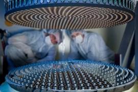
4 4 Historic Monolithic Mirrors In the old days, mirrors had to be thick so that they could be stiff enough to avoid distortion. Thick = weight = bad.

5 5 Historic Monolithic Mirrors In the old days, mirrors had to be thick so that they could be stiff enough to avoid distortion. Thick = weight = bad.
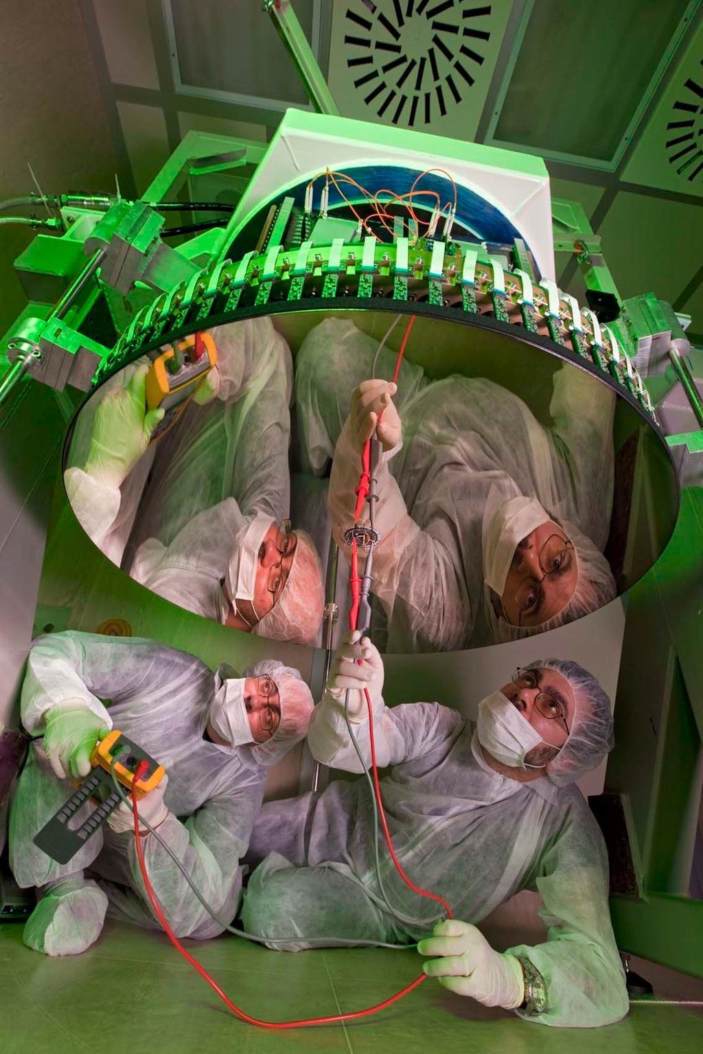
6 6 Modern Mirror Support (LBT) Computer control enables the use of thin, floppy mirrors.
7 7 Modern Mirror Support (LBT) Today mirrors can be thin with shape maintained by computer control.
8 8 Telescope Geometry The overall goal is to create an image of the sky on an, ideally, flat focal plane Start with a simple pinhole camera in the end image sizes scale in the same way.
9 9 Telescope Geometry Lenses collect light over a larger area, but the central ray is undeviated so the pinhole camera concept is still informative.
 to the lens' focus")
.")
10 10 Focal Length and f-number The focal length of a lens is the distance from the lens (actually from its principal plane) to the lens' focus when imaging a point source at infinite distance (parallel incident rays). The f-number of a lens is the ratio of its focal length to its diameter
11 11 Plate scale An arcsecond of angle on the sky maps to some linear dimension at the focal plane of a lens. The plate scale is a number connecting the astronomical angular scale to the physical scale of the detector (in the old days photographic plates thus the name). Via the small angle equation, given the focal length F... mm / arcsec=f ( mm ) / ( mm ) arcsec/ mm= F Since lenses are often described by their focal ratio, f, which is their focal length divided by their diameter, D, so F=fD arcsec/ mm= fd
12 12 Plate scale These equations derive from knowing that rays through the middle of a lens are undeviated. Consider an object subtending an angle of one arcsecond. F one arcsecond x Lens θarcsec x = F You can either set theta to 1 arcsec and solve for x giving you millimeters per arcsecond (assuming you express F in millimeters). Or set x=1mm and derive the number of arcseconds per millimeter. mm / arcsec=f ( mm ) / ( mm ) arcsec/ mm= F
13 13 How a Telescope Works An objective optic (lens or mirror) forms an image. The observer inspects the image formed with a small magnifying glass (the eyepiece). eyepiece objective F objective Magnification = F eyepiece


14 14 Geometrical vs. Physical Optics A raytrace of a parabolic mirror will produce an infinitesimally small point image for an object on the axis of a parabola at infinite distance. In reality, the image size is limited by diffraction to an Airy pattern.
15 15 The Airy Pattern Diffraction blurs light passing through a clear circular aperture. The larger the aperture the smaller the angular blur. The size of the blur is wavelength dependent. Short wavelengths produce sharper images through the same aperture. λ FWHM = 1.03 D λ first null = 1.22 D
16 16 The Airy Pattern Diffraction blurs light passing through a clear circular aperture. The larger the aperture the smaller the angular blur. The size of the blur is wavelength dependent. Short wavelengths produce sharper images through the same aperture. λ FWHM = 1.03 D λ first null = 1.22 D

17 17 The Airy Pattern Diffraction blurs light passing through a clear circular aperture. The larger the aperture the smaller the blur. The size of the blur is wavelength dependent. Short wavelengths produce sharper images through the same aperture. λ FWHM = 1.03 D λ first null = 1.22 D

18 18 The Resolution/Rayleigh Criterion Two stars are considered to be resolved if they are sufficiently separated to fall beyond each other's first Airy nulls. Thus, formally, the resolution of a telescope is 1.22 λ/d.
19 19 Real Point Spread Functions Typically telescope apertures are not clean circles ent_handbook091.png

20 20 Real Point Spread Functions Typically telescope apertures are not clean circles ent_handbook091.png

21 21 Real Point Spread Functions Typically telescope apertures are not clean circles ent_handbook091.png
22 22 Poisson Statistics Why is a sharp high-resolution image important? A small image minimizes the contaminating background and crams the most light into the minimum of detector pixels. Unwanted background = additional noise Detector pixels also contribute noise (readout noise). Fewer pixels per star image is better.
23 23 Poisson Statistics The uncertainty in a measurement in a counting experiment (detecting photons in this case) is equal to the square root of the number of counts. Quantization of light as photons makes astronomical detection a counting experiment Even with a perfect detection system with no noise and no interfering light from background, if you detect 100 photons from a star, the measurement is uncertain by 10 photons, or 10%.


24 24 Detecting Photons At wavelengths where photons are sufficiently energetic (hν > 1 ev) photons can interact with matter to create free electrons. A free electron is a countable electron! In the photoelectric effect photons with energy greater than the work function of the material can eject electrons into free space easily counted. In semiconductors photons can elevate electrons from a bound valence band in to the conduction band producing a solid-state analog of the photoelectric effect. The band-gap in silicon corresponds to the energy of a 1.05um photon.
25 25 Poisson Statistics The uncertainty in a measurement in a counting experiment (detecting photons in this case) is equal to the square root of the number of counts. Quantization of light as photons makes astronomical detection a counting experiment Even with a perfect detection system with no noise and no interfering light from background, if you detect 100 photons from a star, the measurement is uncertain by 10 photons, or 10%. You can't measure a star to a precision of 1% until you have detected 10,000 photons from that star. Complicating this fact is that detection systems aren't perfect and there are contaminating sources of light such as the glow of the sky (and glow of the telescope in the thermal infrared)
26 26 Signal to Noise Ratio Traditionally, astronomers like to express the quality of the detection of a star or spectral line in terms of the ratio of signal to noise (signal-to-noise ratio or SNR). In simplest terms take the number of signal counts and divide by the uncertainty. S/N=10 is a measurement with 10% precision S/N=100 is a measurement with 1% precision 100 photons gets you there if there is no source of contaminating light. 10,000 photons without contamination. In general, if the star is the only source of counts. S N = = ( N ) N ( N )
27 27 Accounting for Background Contamination Sources of background add to the detected photons. These unwanted counts add additional noise. Reducing these backgrounds improve signal-to-noise sharper images (landing on fewer pixels) selecting filter bandpasses to avoid skyglow cooling telescopes used in the thermal infrared If N is the number of counts from the star and B is the number of counts from the background. N SNR= N +B Consider a star which covers 4 pixels, each containing contaminating background vs. one which covers 1 pixel. 4 times lower background in the second case...

28 Sharp images are good: Seeing, Diffraction, and Resolving Power A telescope's resolving power is limited by the worst of... - atmospheric seeing - the twinkling of the stars - diffraction - passing light through an aperture blurs the image. λ first null = 1.22 D 28

 requires a big telescope.")
29 29 Resolving Power A telescope operating at radio wavelengths must have a huge aperture to achieve good resolution. diffraction - passing light through an aperture blurs the image. Working at long wavelengths (e.g. radio) requires a big telescope. Hubble produces sharper images with its ultraviolet cameras than with its infrared cameras.

30 30 Interferometry Multiple small telescopes can be combined to achieve the resolving power of a single giant mirror (but not the light collecting ability).

31 31 The Atacama Large Millimeter Array

32 32 The Atacama Large Millimeter Array

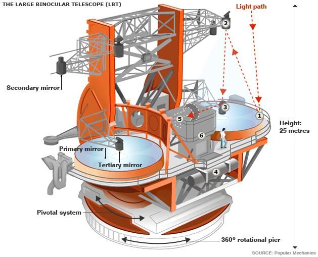
33 33 The Large Binocular Telescope
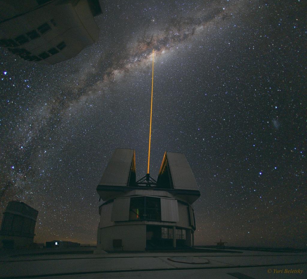
34 34 Fixing Atmospheric Seeing With fast computers and flexible mirrors astronomers can undo the blurring effects of the Earth's atmosphere.


35 35 Fixing Atmospheric Seeing With fast computers and flexible mirrors astronomers can undo the blurring effects of the Earth's atmosphere.
36 36 Fixing Atmospheric Seeing How fast? The critical time is the time it takes atmospheric blobs to blow across their diameter typically 50 milliseconds. Correction has to happen about 10 times faster. These coherent atmospheric patches get effectively bigger as seen at longer wavelengths. Seeing becomes better coherence times become longer. Today adaptive optics is impossible in the visible and feasible at near-infrared wavelengths. Space is still king shortward of 1um.
37 37
38 38


39 39 Optics, Ray Tracing, and Optical Design
.")
40 40 Spherical Aberration An on-axis aberration which arises from different radial zones on a optic producing a focus at different distances. By its geometrical definition, a parabola is free of spherical aberration (but guilty of others).
41 Coma Coma arises when incident rays are not parallel to the optical axis. Like spherical aberration, coma is manifested by different radial zones in the optic Each pair of symmetric points in each radial zone produces a sharp image, but since the lateral magnification is different for each pair each ring of incident rays forms an offset ring producing the classic comma image. 41

42 42 Chromatic Aberration The lensmaker's equation provides the focal length of a lens of a given refractive index, n. Since refractive materials have different refractive index at different wavelength, light comes to a focus in different places.
43 43 Controlling Chromatic Aberration Split the lens into two components (use additional surfaces to control classical aberrations). Make lenses out of materials with different dispersive properties Standard doublet Abbe formula Spherical (fig 6.3)
44 44 Cassegrain Telescopes as Compound Optics A cassegrain telescope is a two-optic system. The primary forms a real image. The secondary, which has a negative focal length, relays this real image to another real image in the focal plane. In a cassegrain configuration the secondary interrupts the converging beam from the primary before the real image forms, but the image is there for calculation's sake nonetheless.
45 45 Atmospheric Transmission The atmosphere blocks most of the electromagnetic spectrum.


46 46 Atmospheric Transmission The atmosphere blocks most of the electromagnetic spectrum.

47 47 Atmospheric Transmission The atmosphere blocks most of the electromagnetic spectrum.
Big League Cryogenics and Vacuum The LHC at CERN
 Big League Cryogenics and Vacuum The LHC at CERN A typical astronomical instrument must maintain about one cubic meter at a pressure of
Applications of Optics
 Nicholas J. Giordano www.cengage.com/physics/giordano Chapter 26 Applications of Optics Marilyn Akins, PhD Broome Community College Applications of Optics Many devices are based on the principles of optics
Chapter 25 Optical Instruments
 Chapter 25 Optical Instruments Units of Chapter 25 Cameras, Film, and Digital The Human Eye; Corrective Lenses Magnifying Glass Telescopes Compound Microscope Aberrations of Lenses and Mirrors Limits of
Why is There a Black Dot when Defocus = 1λ?
 Why is There a Black Dot when Defocus = 1λ? W = W 020 = a 020 ρ 2 When a 020 = 1λ Sag of the wavefront at full aperture (ρ = 1) = 1λ Sag of the wavefront at ρ = 0.707 = 0.5λ Area of the pupil from ρ =
Light gathering Power: Magnification with eyepiece:
 Telescopes Light gathering Power: The amount of light that can be gathered by a telescope in a given amount of time: t 1 /t 2 = (D 2 /D 1 ) 2 The larger the diameter the smaller the amount of time. If
Telescopes and their configurations. Quick review at the GO level
 Telescopes and their configurations Quick review at the GO level Refraction & Reflection Light travels slower in denser material Speed depends on wavelength Image Formation real Focal Length (f) : Distance
Astronomical Cameras
 Astronomical Cameras I. The Pinhole Camera Pinhole Camera (or Camera Obscura) Whenever light passes through a small hole or aperture it creates an image opposite the hole This is an effect wherever apertures
Average: Standard Deviation: Max: 99 Min: 40
 1 st Midterm Exam Average: 83.1 Standard Deviation: 12.0 Max: 99 Min: 40 Please contact me to fix an appointment, if you took less than 65. Chapter 33 Lenses and Op/cal Instruments Units of Chapter 33
Image Formation. Light from distant things. Geometrical optics. Pinhole camera. Chapter 36
 Light from distant things Chapter 36 We learn about a distant thing from the light it generates or redirects. The lenses in our eyes create images of objects our brains can process. This chapter concerns
There is a range of distances over which objects will be in focus; this is called the depth of field of the lens. Objects closer or farther are
 Chapter 25 Optical Instruments Some Topics in Chapter 25 Cameras The Human Eye; Corrective Lenses Magnifying Glass Telescopes Compound Microscope Aberrations of Lenses and Mirrors Limits of Resolution
ECEN 4606, UNDERGRADUATE OPTICS LAB
 ECEN 4606, UNDERGRADUATE OPTICS LAB Lab 2: Imaging 1 the Telescope Original Version: Prof. McLeod SUMMARY: In this lab you will become familiar with the use of one or more lenses to create images of distant
Lecture Outline Chapter 27. Physics, 4 th Edition James S. Walker. Copyright 2010 Pearson Education, Inc.
 Lecture Outline Chapter 27 Physics, 4 th Edition James S. Walker Chapter 27 Optical Instruments Units of Chapter 27 The Human Eye and the Camera Lenses in Combination and Corrective Optics The Magnifying
Lecture PowerPoint. Chapter 25 Physics: Principles with Applications, 6 th edition Giancoli
 Lecture PowerPoint Chapter 25 Physics: Principles with Applications, 6 th edition Giancoli 2005 Pearson Prentice Hall This work is protected by United States copyright laws and is provided solely for the
OPTICS DIVISION B. School/#: Names:
 OPTICS DIVISION B School/#: Names: Directions: Fill in your response for each question in the space provided. All questions are worth two points. Multiple Choice (2 points each question) 1. Which of the
Optical Systems: Pinhole Camera Pinhole camera: simple hole in a box: Called Camera Obscura Aristotle discussed, Al-Hazen analyzed in Book of Optics
 Optical Systems: Pinhole Camera Pinhole camera: simple hole in a box: Called Camera Obscura Aristotle discussed, Al-Hazen analyzed in Book of Optics 1011CE Restricts rays: acts as a single lens: inverts
Two Fundamental Properties of a Telescope
 Two Fundamental Properties of a Telescope 1. Angular Resolution smallest angle which can be seen = 1.22 / D 2. Light-Collecting Area The telescope is a photon bucket A = (D/2)2 D A Parts of the Human Eye
G1 THE NATURE OF EM WAVES AND LIGHT SOURCES
 G1 THE NATURE OF EM WAVES AND LIGHT SOURCES G2 OPTICAL INSTRUMENTS HW/Study Packet Required: READ Tsokos, pp 598-620 SL/HL Supplemental: Hamper, pp 411-450 DO Questions p 605 #1,3 pp 621-623 #6,8,15,18,19,24,26
Classical Optical Solutions
 Petzval Lens Enter Petzval, a Hungarian mathematician. To pursue a prize being offered for the development of a wide-field fast lens system he enlisted Hungarian army members seeing a distraction from
Ch 24. Geometric Optics
 text concept Ch 24. Geometric Optics Fig. 24 3 A point source of light P and its image P, in a plane mirror. Angle of incidence =angle of reflection. text. Fig. 24 4 The blue dashed line through object
Instructor: Doc. Ivan Kassamakov, Assistant: Kalle Hanhijärvi, Doctoral student
 Instructor: Doc. Ivan Kassamakov, Assistant: Kalle Hanhijärvi, Doctoral student Course webpage: http://electronics.physics.helsinki.fi/teaching/optics-2014 Gaussian Optics Errors Taylor series 3 θ sin
25 cm. 60 cm. 50 cm. 40 cm.
 Geometrical Optics 7. The image formed by a plane mirror is: (a) Real. (b) Virtual. (c) Erect and of equal size. (d) Laterally inverted. (e) B, c, and d. (f) A, b and c. 8. A real image is that: (a) Which
General Physics II. Ray Optics
 General Physics II Ray Optics 1 Dispersion White light is a combination of all the wavelengths of the visible part of the electromagnetic spectrum. Red light has the longest wavelengths and violet light
Cardinal Points of an Optical System--and Other Basic Facts
 Cardinal Points of an Optical System--and Other Basic Facts The fundamental feature of any optical system is the aperture stop. Thus, the most fundamental optical system is the pinhole camera. The image
PHYSICS FOR THE IB DIPLOMA CAMBRIDGE UNIVERSITY PRESS
 Option C Imaging C Introduction to imaging Learning objectives In this section we discuss the formation of images by lenses and mirrors. We will learn how to construct images graphically as well as algebraically.
INTRODUCTION THIN LENSES. Introduction. given by the paraxial refraction equation derived last lecture: Thin lenses (19.1) = 1. Double-lens systems
 = 1. Double-lens systems") Chapter 9 OPTICAL INSTRUMENTS Introduction Thin lenses Double-lens systems Aberrations Camera Human eye Compound microscope Summary INTRODUCTION Knowledge of geometrical optics, diffraction and interference,
Chapter 9 OPTICAL INSTRUMENTS Introduction Thin lenses Double-lens systems Aberrations Camera Human eye Compound microscope Summary INTRODUCTION Knowledge of geometrical optics, diffraction and interference,
Chapter 25. Optical Instruments
 Chapter 25 Optical Instruments Optical Instruments Analysis generally involves the laws of reflection and refraction Analysis uses the procedures of geometric optics To explain certain phenomena, the wave
Phys 2310 Mon. Oct. 16, 2017 Today s Topics. Finish Chapter 34: Geometric Optics Homework this Week
 Phys 2310 Mon. Oct. 16, 2017 Today s Topics Finish Chapter 34: Geometric Optics Homework this Week 1 Homework this Week (HW #10) Homework this week due Mon., Oct. 23: Chapter 34: #47, 57, 59, 60, 61, 62,
PHY385H1F Introductory Optics. Practicals Session 7 Studying for Test 2
 PHY385H1F Introductory Optics Practicals Session 7 Studying for Test 2 Entrance Pupil & Exit Pupil A Cooke-triplet consists of three thin lenses in succession, and is often used in cameras. It was patented
Waves & Oscillations
 Physics 42200 Waves & Oscillations Lecture 33 Geometric Optics Spring 2013 Semester Matthew Jones Aberrations We have continued to make approximations: Paraxial rays Spherical lenses Index of refraction
Geometric optics & aberrations
 Geometric optics & aberrations Department of Astrophysical Sciences University AST 542 http://www.northerneye.co.uk/ Outline Introduction: Optics in astronomy Basics of geometric optics Paraxial approximation
Performance Factors. Technical Assistance. Fundamental Optics
 Performance Factors After paraxial formulas have been used to select values for component focal length(s) and diameter(s), the final step is to select actual lenses. As in any engineering problem, this
Geometrical Optics Optical systems
 Phys 322 Lecture 16 Chapter 5 Geometrical Optics Optical systems Magnifying glass Purpose: enlarge a nearby object by increasing its image size on retina Requirements: Image should not be inverted Image
Chapter 36. Image Formation
 Chapter 36 Image Formation Image of Formation Images can result when light rays encounter flat or curved surfaces between two media. Images can be formed either by reflection or refraction due to these
PHYS 202 OUTLINE FOR PART III LIGHT & OPTICS
 PHYS 202 OUTLINE FOR PART III LIGHT & OPTICS Electromagnetic Waves A. Electromagnetic waves S-23,24 1. speed of waves = 1/( o o ) ½ = 3 x 10 8 m/s = c 2. waves and frequency: the spectrum (a) radio red
Lecture 2: Geometrical Optics. Geometrical Approximation. Lenses. Mirrors. Optical Systems. Images and Pupils. Aberrations.
 Lecture 2: Geometrical Optics Outline 1 Geometrical Approximation 2 Lenses 3 Mirrors 4 Optical Systems 5 Images and Pupils 6 Aberrations Christoph U. Keller, Leiden Observatory, keller@strw.leidenuniv.nl
Applied Optics. , Physics Department (Room #36-401) , ,
 , ,") Applied Optics Professor, Physics Department (Room #36-401) 2290-0923, 019-539-0923, shsong@hanyang.ac.kr Office Hours Mondays 15:00-16:30, Wednesdays 15:00-16:30 TA (Ph.D. student, Room #36-415) 2290-0921,
Applied Optics Professor, Physics Department (Room #36-401) 2290-0923, 019-539-0923, shsong@hanyang.ac.kr Office Hours Mondays 15:00-16:30, Wednesdays 15:00-16:30 TA (Ph.D. student, Room #36-415) 2290-0921,
Option G 2: Lenses. The diagram below shows the image of a square grid as produced by a lens that does not cause spherical aberration.
 Name: Date: Option G 2: Lenses 1. This question is about spherical aberration. The diagram below shows the image of a square grid as produced by a lens that does not cause spherical aberration. In the
Lecture 3: Geometrical Optics 1. Spherical Waves. From Waves to Rays. Lenses. Chromatic Aberrations. Mirrors. Outline
 Lecture 3: Geometrical Optics 1 Outline 1 Spherical Waves 2 From Waves to Rays 3 Lenses 4 Chromatic Aberrations 5 Mirrors Christoph U. Keller, Leiden Observatory, keller@strw.leidenuniv.nl Lecture 3: Geometrical
Early Telescopes & Geometrical Optics. C. A. Griffith, Class Notes, PTYS 521, 2016 Not for distribution.
 Early Telescopes & Geometrical Optics C. A. Griffith, Class Notes, PTYS 521, 2016 Not for distribution. 1 1.2. Image Formation Fig. 1. Snell s law indicates the bending of light at the interface of two
Introduction. Geometrical Optics. Milton Katz State University of New York. VfeWorld Scientific New Jersey London Sine Singapore Hong Kong
 Introduction to Geometrical Optics Milton Katz State University of New York VfeWorld Scientific «New Jersey London Sine Singapore Hong Kong TABLE OF CONTENTS PREFACE ACKNOWLEDGMENTS xiii xiv CHAPTER 1:
Lecture 4: Geometrical Optics 2. Optical Systems. Images and Pupils. Rays. Wavefronts. Aberrations. Outline
 Lecture 4: Geometrical Optics 2 Outline 1 Optical Systems 2 Images and Pupils 3 Rays 4 Wavefronts 5 Aberrations Christoph U. Keller, Leiden University, keller@strw.leidenuniv.nl Lecture 4: Geometrical
Chapter 36. Image Formation
 Chapter 36 Image Formation Notation for Mirrors and Lenses The object distance is the distance from the object to the mirror or lens Denoted by p The image distance is the distance from the image to the
COURSE NAME: PHOTOGRAPHY AND AUDIO VISUAL PRODUCTION (VOCATIONAL) FOR UNDER GRADUATE (FIRST YEAR)
 FOR UNDER GRADUATE (FIRST YEAR)") COURSE NAME: PHOTOGRAPHY AND AUDIO VISUAL PRODUCTION (VOCATIONAL) FOR UNDER GRADUATE (FIRST YEAR) PAPER TITLE: BASIC PHOTOGRAPHIC UNIT - 3 : SIMPLE LENS TOPIC: LENS PROPERTIES AND DEFECTS OBJECTIVES By
COURSE NAME: PHOTOGRAPHY AND AUDIO VISUAL PRODUCTION (VOCATIONAL) FOR UNDER GRADUATE (FIRST YEAR) PAPER TITLE: BASIC PHOTOGRAPHIC UNIT - 3 : SIMPLE LENS TOPIC: LENS PROPERTIES AND DEFECTS OBJECTIVES By
Introduction to Light Microscopy. (Image: T. Wittman, Scripps)
") Introduction to Light Microscopy (Image: T. Wittman, Scripps) The Light Microscope Four centuries of history Vibrant current development One of the most widely used research tools A. Khodjakov et al. Major
Introduction to Light Microscopy (Image: T. Wittman, Scripps) The Light Microscope Four centuries of history Vibrant current development One of the most widely used research tools A. Khodjakov et al. Major
Optical Components for Laser Applications. Günter Toesko - Laserseminar BLZ im Dezember
 Günter Toesko - Laserseminar BLZ im Dezember 2009 1 Aberrations An optical aberration is a distortion in the image formed by an optical system compared to the original. It can arise for a number of reasons
Dr. Todd Satogata (ODU/Jefferson Lab) Monday, April
 Monday, April") University Physics 227N/232N Mirrors and Lenses Homework Optics 2 due Friday AM Quiz Friday Optional review session next Monday (Apr 28) Bring Homework Notebooks to Final for Grading Dr. Todd Satogata
University Physics 227N/232N Mirrors and Lenses Homework Optics 2 due Friday AM Quiz Friday Optional review session next Monday (Apr 28) Bring Homework Notebooks to Final for Grading Dr. Todd Satogata
Chapter Ray and Wave Optics
 109 Chapter Ray and Wave Optics 1. An astronomical telescope has a large aperture to [2002] reduce spherical aberration have high resolution increase span of observation have low dispersion. 2. If two
R.B.V.R.R. WOMEN S COLLEGE (AUTONOMOUS) Narayanaguda, Hyderabad.
 Narayanaguda, Hyderabad.") R.B.V.R.R. WOMEN S COLLEGE (AUTONOMOUS) Narayanaguda, Hyderabad. DEPARTMENT OF PHYSICS QUESTION BANK FOR SEMESTER III PAPER III OPTICS UNIT I: 1. MATRIX METHODS IN PARAXIAL OPTICS 2. ABERATIONS UNIT II
R.B.V.R.R. WOMEN S COLLEGE (AUTONOMOUS) Narayanaguda, Hyderabad. DEPARTMENT OF PHYSICS QUESTION BANK FOR SEMESTER III PAPER III OPTICS UNIT I: 1. MATRIX METHODS IN PARAXIAL OPTICS 2. ABERATIONS UNIT II
The Imaging Chain in Optical Astronomy
 The Imaging Chain in Optical Astronomy Review and Overview Imaging Chain includes these elements: 1. energy source 2. object 3. collector 4. detector (or sensor) 5. processor 6. display 7. analysis 8.
The Imaging Chain in Optical Astronomy
 The Imaging Chain in Optical Astronomy 1 Review and Overview Imaging Chain includes these elements: 1. energy source 2. object 3. collector 4. detector (or sensor) 5. processor 6. display 7. analysis 8.
OPTICAL IMAGING AND ABERRATIONS
 OPTICAL IMAGING AND ABERRATIONS PARTI RAY GEOMETRICAL OPTICS VIRENDRA N. MAHAJAN THE AEROSPACE CORPORATION AND THE UNIVERSITY OF SOUTHERN CALIFORNIA SPIE O P T I C A L E N G I N E E R I N G P R E S S A
PHYSICS. Chapter 35 Lecture FOR SCIENTISTS AND ENGINEERS A STRATEGIC APPROACH 4/E RANDALL D. KNIGHT
 PHYSICS FOR SCIENTISTS AND ENGINEERS A STRATEGIC APPROACH 4/E Chapter 35 Lecture RANDALL D. KNIGHT Chapter 35 Optical Instruments IN THIS CHAPTER, you will learn about some common optical instruments and
Physics 1C. Lecture 25B
 Physics 1C Lecture 25B "More than 50 years ago, Austrian researcher Ivo Kohler gave people goggles thats severely distorted their vision: The lenses turned the world upside down. After several weeks, subjects
AN INTRODUCTION TO CHROMATIC ABERRATION IN REFRACTORS
 AN INTRODUCTION TO CHROMATIC ABERRATION IN REFRACTORS The popularity of high-quality refractors draws attention to color correction in such instruments. There are several point of confusion and misconceptions.
[ Summary. 3i = 1* 6i = 4J;
 the projections at angle 2. We calculate the difference between the measured projections at angle 2 (6 and 14) and the projections based on the previous esti mate (top row: 2>\ + 6\ = 10; same for bottom
Observational Astronomy
 Observational Astronomy Instruments The telescope- instruments combination forms a tightly coupled system: Telescope = collecting photons and forming an image Instruments = registering and analyzing the
Warren J. Smith Chief Scientist, Consultant Rockwell Collins Optronics Carlsbad, California
 Modern Optical Engineering The Design of Optical Systems Warren J. Smith Chief Scientist, Consultant Rockwell Collins Optronics Carlsbad, California Fourth Edition Me Graw Hill New York Chicago San Francisco
OPTICAL SYSTEMS OBJECTIVES
 101 L7 OPTICAL SYSTEMS OBJECTIVES Aims Your aim here should be to acquire a working knowledge of the basic components of optical systems and understand their purpose, function and limitations in terms
Astronomy 80 B: Light. Lecture 9: curved mirrors, lenses, aberrations 29 April 2003 Jerry Nelson
 Astronomy 80 B: Light Lecture 9: curved mirrors, lenses, aberrations 29 April 2003 Jerry Nelson Sensitive Countries LLNL field trip 2003 April 29 80B-Light 2 Topics for Today Optical illusion Reflections
Chapter 34 Geometric Optics (also known as Ray Optics) by C.-R. Hu
 by C.-R. Hu") Chapter 34 Geometric Optics (also known as Ray Optics) by C.-R. Hu 1. Principles of image formation by mirrors (1a) When all length scales of objects, gaps, and holes are much larger than the wavelength
Chapter 34 Geometric Optics (also known as Ray Optics) by C.-R. Hu 1. Principles of image formation by mirrors (1a) When all length scales of objects, gaps, and holes are much larger than the wavelength
Waves & Oscillations
 Physics 42200 Waves & Oscillations Lecture 27 Geometric Optics Spring 205 Semester Matthew Jones Sign Conventions > + = Convex surface: is positive for objects on the incident-light side is positive for
TSBB09 Image Sensors 2018-HT2. Image Formation Part 1
 TSBB09 Image Sensors 2018-HT2 Image Formation Part 1 Basic physics Electromagnetic radiation consists of electromagnetic waves With energy That propagate through space The waves consist of transversal
Physics 431 Final Exam Examples (3:00-5:00 pm 12/16/2009) TIME ALLOTTED: 120 MINUTES Name: Signature:
 TIME ALLOTTED: 120 MINUTES Name: Signature:") Physics 431 Final Exam Examples (3:00-5:00 pm 12/16/2009) TIME ALLOTTED: 120 MINUTES Name: PID: Signature: CLOSED BOOK. TWO 8 1/2 X 11 SHEET OF NOTES (double sided is allowed), AND SCIENTIFIC POCKET CALCULATOR
Physics 431 Final Exam Examples (3:00-5:00 pm 12/16/2009) TIME ALLOTTED: 120 MINUTES Name: PID: Signature: CLOSED BOOK. TWO 8 1/2 X 11 SHEET OF NOTES (double sided is allowed), AND SCIENTIFIC POCKET CALCULATOR
a) How big will that physical image of the cells be your camera sensor?
 How big will that physical image of the cells be your camera sensor?") 1. Consider a regular wide-field microscope set up with a 60x, NA = 1.4 objective and a monochromatic digital camera with 8 um pixels, properly positioned in the primary image plane. This microscope is
1. Consider a regular wide-field microscope set up with a 60x, NA = 1.4 objective and a monochromatic digital camera with 8 um pixels, properly positioned in the primary image plane. This microscope is
Physics 1202: Lecture 19 Today s Agenda
 Physics 1202: Lecture 19 Today s Agenda Announcements: Team problems today Team 12: Kervell Baird, Matthew George, Derek Schultz Team 13: Paxton Stowik, Stacey Ann Burke Team 14: Gregory Desautels, Benjamin
Reflection! Reflection and Virtual Image!
 1/30/14 Reflection - wave hits non-absorptive surface surface of a smooth water pool - incident vs. reflected wave law of reflection - concept for all electromagnetic waves - wave theory: reflected back
EE119 Introduction to Optical Engineering Spring 2002 Final Exam. Name:
 EE119 Introduction to Optical Engineering Spring 2002 Final Exam Name: SID: CLOSED BOOK. FOUR 8 1/2 X 11 SHEETS OF NOTES, AND SCIENTIFIC POCKET CALCULATOR PERMITTED. TIME ALLOTTED: 180 MINUTES Fundamental
VISUAL PHYSICS ONLINE DEPTH STUDY: ELECTRON MICROSCOPES
 VISUAL PHYSICS ONLINE DEPTH STUDY: ELECTRON MICROSCOPES Shortly after the experimental confirmation of the wave properties of the electron, it was suggested that the electron could be used to examine objects
Chapter 2 - Geometric Optics
 David J. Starling Penn State Hazleton PHYS 214 The human eye is a visual system that collects light and forms an image on the retina. The human eye is a visual system that collects light and forms an image
Binocular and Scope Performance 57. Diffraction Effects
 Binocular and Scope Performance 57 Diffraction Effects The resolving power of a perfect optical system is determined by diffraction that results from the wave nature of light. An infinitely distant point
Lens Design I. Lecture 3: Properties of optical systems II Herbert Gross. Summer term
 Lens Design I Lecture 3: Properties of optical systems II 207-04-20 Herbert Gross Summer term 207 www.iap.uni-jena.de 2 Preliminary Schedule - Lens Design I 207 06.04. Basics 2 3.04. Properties of optical
DESIGN NOTE: DIFFRACTION EFFECTS
 NASA IRTF / UNIVERSITY OF HAWAII Document #: TMP-1.3.4.2-00-X.doc Template created on: 15 March 2009 Last Modified on: 5 April 2010 DESIGN NOTE: DIFFRACTION EFFECTS Original Author: John Rayner NASA Infrared
Lens Design I. Lecture 3: Properties of optical systems II Herbert Gross. Summer term
 Lens Design I Lecture 3: Properties of optical systems II 205-04-8 Herbert Gross Summer term 206 www.iap.uni-jena.de 2 Preliminary Schedule 04.04. Basics 2.04. Properties of optical systrems I 3 8.04.
12:40-2:40 3:00-4:00 PM
 Physics 294H l Professor: Joey Huston l email:huston@msu.edu l office: BPS3230 l Homework will be with Mastering Physics (and an average of 1 hand-written problem per week) Help-room hours: 12:40-2:40
Chapter 23. Light Geometric Optics
 Chapter 23. Light Geometric Optics There are 3 basic ways to gather light and focus it to make an image. Pinhole - Simple geometry Mirror - Reflection Lens - Refraction Pinhole Camera Image Formation (the
Converging and Diverging Surfaces. Lenses. Converging Surface
 Lenses Sandy Skoglund 2 Converging and Diverging s AIR Converging If the surface is convex, it is a converging surface in the sense that the parallel rays bend toward each other after passing through the
The Optics of Mirrors
 Use with Text Pages 558 563 The Optics of Mirrors Use the terms in the list below to fill in the blanks in the paragraphs about mirrors. reversed smooth eyes concave focal smaller reflect behind ray convex
PHYS 160 Astronomy. When analyzing light s behavior in a mirror or lens, it is helpful to use a technique called ray tracing.
 Optics Introduction In this lab, we will be exploring several properties of light including diffraction, reflection, geometric optics, and interference. There are two sections to this lab and they may
Chapter 34 Geometric Optics
 Chapter 34 Geometric Optics Lecture by Dr. Hebin Li Goals of Chapter 34 To see how plane and curved mirrors form images To learn how lenses form images To understand how a simple image system works Reflection
Physics Chapter Review Chapter 25- The Eye and Optical Instruments Ethan Blitstein
 Physics Chapter Review Chapter 25- The Eye and Optical Instruments Ethan Blitstein The Human Eye As light enters through the human eye it first passes through the cornea (a thin transparent membrane of
Lecture 21. Physics 1202: Lecture 21 Today s Agenda
 Physics 1202: Lecture 21 Today s Agenda Announcements: Team problems today Team 14: Gregory Desautels, Benjamin Hallisey, Kyle Mcginnis Team 15: Austin Dion, Nicholas Gandza, Paul Macgillis-Falcon Homework
Chapters 1 & 2. Definitions and applications Conceptual basis of photogrammetric processing
 Chapters 1 & 2 Chapter 1: Photogrammetry Definitions and applications Conceptual basis of photogrammetric processing Transition from two-dimensional imagery to three-dimensional information Automation
Chapter 23. Mirrors and Lenses
 Chapter 23 Mirrors and Lenses Notation for Mirrors and Lenses The object distance is the distance from the object to the mirror or lens Denoted by p The image distance is the distance from the image to
Chapter 34 The Wave Nature of Light; Interference. Copyright 2009 Pearson Education, Inc.
 Chapter 34 The Wave Nature of Light; Interference 34-7 Luminous Intensity The intensity of light as perceived depends not only on the actual intensity but also on the sensitivity of the eye at different
ECEG105/ECEU646 Optics for Engineers Course Notes Part 4: Apertures, Aberrations Prof. Charles A. DiMarzio Northeastern University Fall 2008
 ECEG105/ECEU646 Optics for Engineers Course Notes Part 4: Apertures, Aberrations Prof. Charles A. DiMarzio Northeastern University Fall 2008 July 2003+ Chuck DiMarzio, Northeastern University 11270-04-1
PHY385H1F Introductory Optics Term Test 2 November 6, 2012 Duration: 50 minutes. NAME: Student Number:.
 PHY385H1F Introductory Optics Term Test 2 November 6, 2012 Duration: 50 minutes NAME: Student Number:. Aids allowed: A pocket calculator with no communication ability. One 8.5x11 aid sheet, written on
GEOMETRICAL OPTICS AND OPTICAL DESIGN
 GEOMETRICAL OPTICS AND OPTICAL DESIGN Pantazis Mouroulis Associate Professor Center for Imaging Science Rochester Institute of Technology John Macdonald Senior Lecturer Physics Department University of
CH. 23 Mirrors and Lenses HW# 6, 7, 9, 11, 13, 21, 25, 31, 33, 35
 CH. 23 Mirrors and Lenses HW# 6, 7, 9, 11, 13, 21, 25, 31, 33, 35 Mirrors Rays of light reflect off of mirrors, and where the reflected rays either intersect or appear to originate from, will be the location
Image Formation and Camera Design
 Image Formation and Camera Design Spring 2003 CMSC 426 Jan Neumann 2/20/03 Light is all around us! From London & Upton, Photography Conventional camera design... Ken Kay, 1969 in Light & Film, TimeLife
Chapter 23. Mirrors and Lenses
 Chapter 23 Mirrors and Lenses Mirrors and Lenses The development of mirrors and lenses aided the progress of science. It led to the microscopes and telescopes. Allowed the study of objects from microbes
EE119 Introduction to Optical Engineering Spring 2003 Final Exam. Name:
 EE119 Introduction to Optical Engineering Spring 2003 Final Exam Name: SID: CLOSED BOOK. THREE 8 1/2 X 11 SHEETS OF NOTES, AND SCIENTIFIC POCKET CALCULATOR PERMITTED. TIME ALLOTTED: 180 MINUTES Fundamental
Section 2 concludes that a glare meter based on a digital camera is probably too expensive to develop and produce, and may not be simple in use.
 Possible development of a simple glare meter Kai Sørensen, 17 September 2012 Introduction, summary and conclusion Disability glare is sometimes a problem in road traffic situations such as: - at road works
Section A Conceptual and application type questions. 1 Which is more observable diffraction of light or sound? Justify. (1)
") INDIAN SCHOOL MUSCAT Department of Physics Class : XII Physics Worksheet - 6 (2017-2018) Chapter 9 and 10 : Ray Optics and wave Optics Section A Conceptual and application type questions 1 Which is more
INDIAN SCHOOL MUSCAT Department of Physics Class : XII Physics Worksheet - 6 (2017-2018) Chapter 9 and 10 : Ray Optics and wave Optics Section A Conceptual and application type questions 1 Which is more
IMAGE FORMATION. Light source properties. Sensor characteristics Surface. Surface reflectance properties. Optics
 IMAGE FORMATION Light source properties Sensor characteristics Surface Exposure shape Optics Surface reflectance properties ANALOG IMAGES An image can be understood as a 2D light intensity function f(x,y)
CCAM Microscope Objectives
 CCAM Microscope Objectives Things to consider when selecting an objective Magnification Numerical Aperture (NA) resolving power and light intensity of the objective Working Distance distance between the
CHAPTER TWO METALLOGRAPHY & MICROSCOPY
 CHAPTER TWO METALLOGRAPHY & MICROSCOPY 1. INTRODUCTION: Materials characterisation has two main aspects: Accurately measuring the physical, mechanical and chemical properties of materials Accurately measuring
Mirrors and Lenses. Images can be formed by reflection from mirrors. Images can be formed by refraction through lenses.
 Mirrors and Lenses Images can be formed by reflection from mirrors. Images can be formed by refraction through lenses. Notation for Mirrors and Lenses The object distance is the distance from the object
Chapter 18 Optical Elements
 Chapter 18 Optical Elements GOALS When you have mastered the content of this chapter, you will be able to achieve the following goals: Definitions Define each of the following terms and use it in an operational
Optical Design with Zemax
 Optical Design with Zemax Lecture : Correction II 3--9 Herbert Gross Summer term www.iap.uni-jena.de Correction II Preliminary time schedule 6.. Introduction Introduction, Zemax interface, menues, file