Big League Cryogenics and Vacuum The LHC at CERN
|
|
|
- Noel Golden
- 5 years ago
- Views:
Transcription
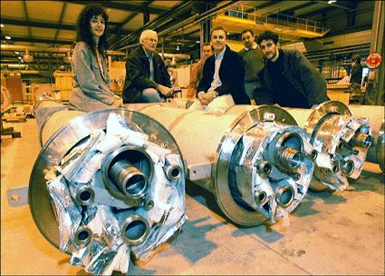
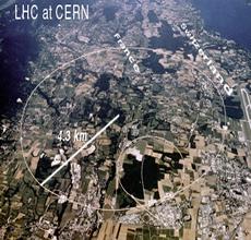
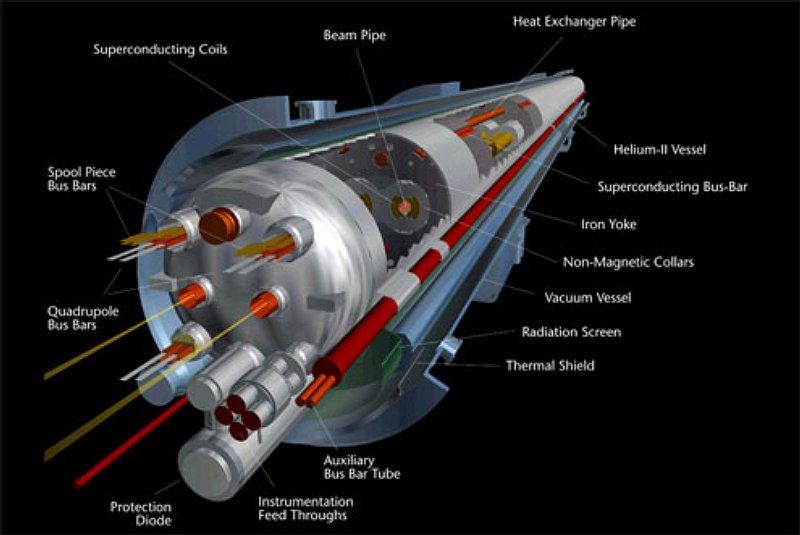
1 Big League Cryogenics and Vacuum The LHC at CERN A typical astronomical instrument must maintain about one cubic meter at a pressure of <0.1 millitorr. The Large Hadron Collider at CERN is 27 kilometers in circumference and contains two beam pipes that must be held <10^{-9} millitorr for months at a time. The accelerator uses hundreds of superconducting magnets which must be cooled to <4K. 700,000 liters of superfluid liquid helium (superfluid to minimize distribution losses and improve energy transfer). 200 kilometers of cryogenic piping, 40,000 junctions, 1700 cryogenic valves...
2

3 Optics, Ray Tracing, and Optical Design

4 Geometrical vs. Physical Optics Geometrical Optics traces rays through the system Reflection and refraction occur based on purely geometrical relationships (e.g. Snell's Law) Images are constructed from the intersection points of a bundle of individually traced rays with a focal plane. Rays do not interact with one another. Physical Optics accounts for the wave nature of light. An incident ray is represented by a plane wavefront. Wave propagation and interference determine the illumination within the system. Naturally accounts for interference and diffraction.


5 Geometrical vs. Physical Optics A raytrace of a parabolic mirror will produce an infinitesimally small point image for an object on the axis of a parabola at infinite distance. In reality, the image size is limited by diffraction to an Airy pattern.
 A surface can also serve as a stop")
6 Geometrical Optics and Surfaces The basic unit of optical design is the surface (not the lens...). Surfaces can redirect rays either through reflection / refraction obscuration/scattering diffraction (but this is physical optics) A surface can also serve as a stop without redirecting any rays. A stop is simply an obscuration/hole.

7 Reflection Reflection simply requires equal angles of incidence and emergence for a ray independent of material. The only wavelength dependent quantity is reflection efficiency (which will not affect image shape).

8 Reflection and Virtual Images


9 Refraction and Snell's Law Note that the refractive index, n, is a wavelength dependent quantity
10 Raytracing 101: The Paraxial Approximation A raytrace follows the propagation of a ray through an optical system one surface at a time, calculating the deviation from reflection or refraction at each surface. The paraxial approximation provides a starting point for the overall system layout image positions, focal lengths, etc. - by calculating ray propagation infinitesimally close to the optical axis. This is the regime where sin = and thus where images are perfect and their positions are readily calculated. Due to aberration the paraxial focus can be significantly different from the best focal position.
.")
11 Focal Length, f/number, and the Lensmakers Equation The focal length of a lens is the distance from the lens (actually from its principal plane) to the lens' focus when imaging a point source at infinite distance (parallel incident rays). In practice, the paraxial focal length of the lens is quoted.


12 Aside One of my Favorite Books...
13 Focal Length and the Lensmaker's Equation The focal length of a lens is the distance from the lens (actually its principal plane) to the lens' focus when imaging a point source on the optical axis. For a ''thin'' lens the focal length is given by This equation applies for a thin lens in vacuum (or air). n is the refractive index of the lens material r is the radius of curvature (convex to the left is positive curvature)
14 Focal Ratio The focal ratio (f/#) characterizes the rate of convergence of a bundle of rays as they form an image. A lens (or system of lenses) will have a fixed focal length, but its focal ratio will depend on the aperture of its stop. Focal ratio is simply the inverse of the beam's divergence per unit length. a beam that broadens 1 cm for every 10 cm of propagation is an f/10 beam.
15 Focal Ratio and Depth of Field f/8 f/2 High focal ratios (e.g. f/20) imply a narrow pencil of converging rays a slow (from photographic exposure time) optical system. Low focal ratios (e.g. f/2) indicate convergence over a wide angle and thus a fast system.
16 Focal Ratio and Depth of Field Fast systems are prone to optical aberration (due to the large range of ray angles incident on the optics. f/8 f/2 difficult to focus. A small shift in focal plane position produces significant blurring of the image Essential for wide-field imaging or broadband spectroscopy (where a wide range of angles much to be focused onto a surface)
17 Raytracing 101: Ray Height In analyzing a lens system, particularly one that is axially symmetric, characteristics of ray propagation can be paramaterized in terms of ray height from the optical axis. Rays of infinitesimal height are the paraxial rays. For most real optics, image position (as defined by ray intersection is a function of ray height). That is, an optic will focus light from different radial zones on the optic at different distances producing an aberrated image.
18 Raytracing 101: Ray Height
19 Tracking of rays can be accomplished computationally or, even, physically.
20 Images and Objects A lens will form an image of an object at a position dictated by the focal length. Images and objects can be virtual, meaning that divergent rays imply the existence of an object at their apparent convergent point. Images, either real or virtual, serve as objects for subsequent elements.
21 Conjugate Images and Objects An object and its corresponding image are ''conjugate'' points. The conjugate of an object at infinite distance is an image one focal length from the lens. An object placed at a focal point has its conjugate image at infinite distance. Emergent rays from the lens are parallel -- the basis of ''collimation''
22 Locating Conjugate Points By identifying a ray through a focus or parallel to the optical axis a ray through lens center one can graphically construct an image corresponding to a given object.

23 Compound Optics Virtually all optical systems contain two or more elements. Most systems can be reduced to an equivalent single thin lens. The final focus (and focal ratios) can be propagated through the system one object/image pair at a time.
24 Compound Optics Virtually all optical systems contain two or more elements. Most systems can be reduced to an equivalent single thin lens. The final focus (and focal ratios) can be propagated through the system one object/image pair at a time.

25 Cassegrain Telescopes as Compound Optics A cassegrain telescope is a two-optic system. The primary forms a real image. The secondary, which has a negative focal length, relays this real image to another real image in the focal plane. In a cassegrain configuration the secondary interrupts the converging beam from the primary before the real image forms, but the image is there for calculation's sake nonetheless.
26 Cassegrain Telescopes as Compound Optics A cassegrain telescope is a two-optic system. The primary forms a real image. The secondary, which has a negative focal length, relays this real image to another real image in the focal plane. In a cassegrain configuration the secondary interrupts the converging beam from the primary before the real image forms, but the image is there for calculation's sake nonetheless.

27 Gregorian Telescopes In the Gregorian configuration the secondary mirror lies beyond the prime focus of the primary. A real image is formed in space ahead of the secondary.
28 Infrared Design Reimaging Optics Most CCD detectors are placed directly at the primary focal plane of the telescope. Such a configuration would sacrifice considerable sensitivity to thermal background for infrared work. An infrared system should view a little warm solid angle as possible, preferably only seeing low-emissivity mirror surfaces on the way to the cold sky. Place focal plane here??
 = 1.7e-06 B(300K, 2.0um) = 1.4e+03 B(300K, 3.0um) = 5.7e+05 B(200K, 2.0um) = 8.")
29 Blackbody Radiation Ambient thermal blackbody emission becomes significant at room temperature (300K) at wavelengths longward of 2 micrometers B(300K, 1.0um) = 1.7e-06 B(300K, 2.0um) = 1.4e+03 B(300K, 3.0um) = 5.7e+05 B(200K, 2.0um) = 8.9e-03
30 Blackbody Emission/Detection Geometry
31 Blackbody Geometry The Planck equation quantifies the amount of light emitted by a unit area of a perfect blackbody into a given solid angle per unit bandpass. Imperfect emitters are characterized by their emissivity as a function of wavelength,. Astronomically, the solid angle of interest is the aperture of the telescope as seen from the surface of the target. Similarly the blackbody area of interest is the surface area of the blackbody viewed by a pixel. If the blackbody is unresolved then the area of interest is the projected area of the entire blackbody.
32 Infrared Design Reimaging Optics In order to limit the rays seen by the detector, collimate and re-image the primary focal plane. Re-imaging provides two advantages Control over final platescale as the f/# of the final focus is now under the designer's control. The collimating lens forms an image of the primary mirror (which is as good as having the original right there) within the cold volume of the instrument. All warm surfaces can be masked. Place re-imaging optics here!
33 Infrared Design Issues Reimaging Optics An image of the telescope primary (pupil) is formed about one focal length behind the collimating lens. In addition to being the location to mask off high emissivity surfaces, this location is also ideal for placing filters, polarizers, grisms light from a star is spread uniformly over the full aperture the pupil marks a minimum diameter waist in the optical system permitting the smallest components Pupil Image Cassegrain focal plane Reimaged Focal Plane
34 Infrared Design Issues Reimaging Optics Reimaging in practice The TripleSpec slit viewing optics.
35 Lens aberrations The paraxial approximation holds for cases where sin (the small angle approximation). More exactly, the series expansion of sin is: Classical aberrations of optical systems can be traced to the third order terms in the expansion. These 5 classical aberrations -- spherical, coma, astigmatism, distortion, and field curvature were enumerated by von Seidel and bear his name.
36 Spherical Aberration An ''on-axis'' aberration which arises from different radial zones on an optic having different focal lengths. A parabola is the only single optical element free of spherical aberration.
Reflectors vs. Refractors
 1 Telescope Types - Telescopes collect and concentrate light (which can then be magnified, dispersed as a spectrum, etc). - In the end it is the collecting area that counts. - There are two primary telescope
Image Formation. Light from distant things. Geometrical optics. Pinhole camera. Chapter 36
 Light from distant things Chapter 36 We learn about a distant thing from the light it generates or redirects. The lenses in our eyes create images of objects our brains can process. This chapter concerns
Lecture 4: Geometrical Optics 2. Optical Systems. Images and Pupils. Rays. Wavefronts. Aberrations. Outline
 Lecture 4: Geometrical Optics 2 Outline 1 Optical Systems 2 Images and Pupils 3 Rays 4 Wavefronts 5 Aberrations Christoph U. Keller, Leiden University, keller@strw.leidenuniv.nl Lecture 4: Geometrical
Lecture 2: Geometrical Optics. Geometrical Approximation. Lenses. Mirrors. Optical Systems. Images and Pupils. Aberrations.
 Lecture 2: Geometrical Optics Outline 1 Geometrical Approximation 2 Lenses 3 Mirrors 4 Optical Systems 5 Images and Pupils 6 Aberrations Christoph U. Keller, Leiden Observatory, keller@strw.leidenuniv.nl
Performance Factors. Technical Assistance. Fundamental Optics
 Performance Factors After paraxial formulas have been used to select values for component focal length(s) and diameter(s), the final step is to select actual lenses. As in any engineering problem, this
Lecture 2: Geometrical Optics. Geometrical Approximation. Lenses. Mirrors. Optical Systems. Images and Pupils. Aberrations.
 Lecture 2: Geometrical Optics Outline 1 Geometrical Approximation 2 Lenses 3 Mirrors 4 Optical Systems 5 Images and Pupils 6 Aberrations Christoph U. Keller, Leiden Observatory, keller@strw.leidenuniv.nl
Classical Optical Solutions
 Petzval Lens Enter Petzval, a Hungarian mathematician. To pursue a prize being offered for the development of a wide-field fast lens system he enlisted Hungarian army members seeing a distraction from
Geometric optics & aberrations
 Geometric optics & aberrations Department of Astrophysical Sciences University AST 542 http://www.northerneye.co.uk/ Outline Introduction: Optics in astronomy Basics of geometric optics Paraxial approximation
Chapter Ray and Wave Optics
 109 Chapter Ray and Wave Optics 1. An astronomical telescope has a large aperture to [2002] reduce spherical aberration have high resolution increase span of observation have low dispersion. 2. If two
Mirrors and Lenses. Images can be formed by reflection from mirrors. Images can be formed by refraction through lenses.
 Mirrors and Lenses Images can be formed by reflection from mirrors. Images can be formed by refraction through lenses. Notation for Mirrors and Lenses The object distance is the distance from the object
Chapters 1 & 2. Definitions and applications Conceptual basis of photogrammetric processing
 Chapters 1 & 2 Chapter 1: Photogrammetry Definitions and applications Conceptual basis of photogrammetric processing Transition from two-dimensional imagery to three-dimensional information Automation
Lens Design I. Lecture 3: Properties of optical systems II Herbert Gross. Summer term
 Lens Design I Lecture 3: Properties of optical systems II 205-04-8 Herbert Gross Summer term 206 www.iap.uni-jena.de 2 Preliminary Schedule 04.04. Basics 2.04. Properties of optical systrems I 3 8.04.
PHYS 160 Astronomy. When analyzing light s behavior in a mirror or lens, it is helpful to use a technique called ray tracing.
 Optics Introduction In this lab, we will be exploring several properties of light including diffraction, reflection, geometric optics, and interference. There are two sections to this lab and they may
Lens Design I. Lecture 3: Properties of optical systems II Herbert Gross. Summer term
 Lens Design I Lecture 3: Properties of optical systems II 207-04-20 Herbert Gross Summer term 207 www.iap.uni-jena.de 2 Preliminary Schedule - Lens Design I 207 06.04. Basics 2 3.04. Properties of optical
Lecture 3: Geometrical Optics 1. Spherical Waves. From Waves to Rays. Lenses. Chromatic Aberrations. Mirrors. Outline
 Lecture 3: Geometrical Optics 1 Outline 1 Spherical Waves 2 From Waves to Rays 3 Lenses 4 Chromatic Aberrations 5 Mirrors Christoph U. Keller, Leiden Observatory, keller@strw.leidenuniv.nl Lecture 3: Geometrical
ECEN 4606, UNDERGRADUATE OPTICS LAB
 ECEN 4606, UNDERGRADUATE OPTICS LAB Lab 2: Imaging 1 the Telescope Original Version: Prof. McLeod SUMMARY: In this lab you will become familiar with the use of one or more lenses to create images of distant
Cardinal Points of an Optical System--and Other Basic Facts
 Cardinal Points of an Optical System--and Other Basic Facts The fundamental feature of any optical system is the aperture stop. Thus, the most fundamental optical system is the pinhole camera. The image
OPTICS DIVISION B. School/#: Names:
 OPTICS DIVISION B School/#: Names: Directions: Fill in your response for each question in the space provided. All questions are worth two points. Multiple Choice (2 points each question) 1. Which of the
Waves & Oscillations
 Physics 42200 Waves & Oscillations Lecture 33 Geometric Optics Spring 2013 Semester Matthew Jones Aberrations We have continued to make approximations: Paraxial rays Spherical lenses Index of refraction
Chapter 18 Optical Elements
 Chapter 18 Optical Elements GOALS When you have mastered the content of this chapter, you will be able to achieve the following goals: Definitions Define each of the following terms and use it in an operational
Astronomy 80 B: Light. Lecture 9: curved mirrors, lenses, aberrations 29 April 2003 Jerry Nelson
 Astronomy 80 B: Light Lecture 9: curved mirrors, lenses, aberrations 29 April 2003 Jerry Nelson Sensitive Countries LLNL field trip 2003 April 29 80B-Light 2 Topics for Today Optical illusion Reflections
Algebra Based Physics. Reflection. Slide 1 / 66 Slide 2 / 66. Slide 3 / 66. Slide 4 / 66. Slide 5 / 66. Slide 6 / 66.
 Slide 1 / 66 Slide 2 / 66 Algebra Based Physics Geometric Optics 2015-12-01 www.njctl.org Slide 3 / 66 Slide 4 / 66 Table of ontents lick on the topic to go to that section Reflection Refraction and Snell's
Scaling relations for telescopes, spectrographs, and reimaging instruments
 Scaling relations for telescopes, spectrographs, and reimaging instruments Benjamin Weiner Steward Observatory University of Arizona bjw @ asarizonaedu 19 September 2008 1 Introduction To make modern astronomical
25 cm. 60 cm. 50 cm. 40 cm.
 Geometrical Optics 7. The image formed by a plane mirror is: (a) Real. (b) Virtual. (c) Erect and of equal size. (d) Laterally inverted. (e) B, c, and d. (f) A, b and c. 8. A real image is that: (a) Which
Some of the important topics needed to be addressed in a successful lens design project (R.R. Shannon: The Art and Science of Optical Design)
") Lens design Some of the important topics needed to be addressed in a successful lens design project (R.R. Shannon: The Art and Science of Optical Design) Focal length (f) Field angle or field size F/number
Lens design Some of the important topics needed to be addressed in a successful lens design project (R.R. Shannon: The Art and Science of Optical Design) Focal length (f) Field angle or field size F/number
OPTICAL IMAGING AND ABERRATIONS
 OPTICAL IMAGING AND ABERRATIONS PARTI RAY GEOMETRICAL OPTICS VIRENDRA N. MAHAJAN THE AEROSPACE CORPORATION AND THE UNIVERSITY OF SOUTHERN CALIFORNIA SPIE O P T I C A L E N G I N E E R I N G P R E S S A
Applied Optics. , Physics Department (Room #36-401) , ,
 , ,") Applied Optics Professor, Physics Department (Room #36-401) 2290-0923, 019-539-0923, shsong@hanyang.ac.kr Office Hours Mondays 15:00-16:30, Wednesdays 15:00-16:30 TA (Ph.D. student, Room #36-415) 2290-0921,
Applied Optics Professor, Physics Department (Room #36-401) 2290-0923, 019-539-0923, shsong@hanyang.ac.kr Office Hours Mondays 15:00-16:30, Wednesdays 15:00-16:30 TA (Ph.D. student, Room #36-415) 2290-0921,
Ch 24. Geometric Optics
 text concept Ch 24. Geometric Optics Fig. 24 3 A point source of light P and its image P, in a plane mirror. Angle of incidence =angle of reflection. text. Fig. 24 4 The blue dashed line through object
OPAC 202 Optical Design and Inst.
 OPAC 202 Optical Design and Inst. Topic 9 Aberrations Department of http://www.gantep.edu.tr/~bingul/opac202 Optical & Acustical Engineering Gaziantep University Apr 2018 Sayfa 1 Introduction The influences
Opti 415/515. Introduction to Optical Systems. Copyright 2009, William P. Kuhn
 Opti 415/515 Introduction to Optical Systems 1 Optical Systems Manipulate light to form an image on a detector. Point source microscope Hubble telescope (NASA) 2 Fundamental System Requirements Application
Optical Systems: Pinhole Camera Pinhole camera: simple hole in a box: Called Camera Obscura Aristotle discussed, Al-Hazen analyzed in Book of Optics
 Optical Systems: Pinhole Camera Pinhole camera: simple hole in a box: Called Camera Obscura Aristotle discussed, Al-Hazen analyzed in Book of Optics 1011CE Restricts rays: acts as a single lens: inverts
Chapter 36. Image Formation
 Chapter 36 Image Formation Image of Formation Images can result when light rays encounter flat or curved surfaces between two media. Images can be formed either by reflection or refraction due to these
Chapter 34 Geometric Optics
 Chapter 34 Geometric Optics Lecture by Dr. Hebin Li Goals of Chapter 34 To see how plane and curved mirrors form images To learn how lenses form images To understand how a simple image system works Reflection
Chapter 23. Light Geometric Optics
 Chapter 23. Light Geometric Optics There are 3 basic ways to gather light and focus it to make an image. Pinhole - Simple geometry Mirror - Reflection Lens - Refraction Pinhole Camera Image Formation (the
OPTICAL SYSTEMS OBJECTIVES
 101 L7 OPTICAL SYSTEMS OBJECTIVES Aims Your aim here should be to acquire a working knowledge of the basic components of optical systems and understand their purpose, function and limitations in terms
GEOMETRICAL OPTICS AND OPTICAL DESIGN
 GEOMETRICAL OPTICS AND OPTICAL DESIGN Pantazis Mouroulis Associate Professor Center for Imaging Science Rochester Institute of Technology John Macdonald Senior Lecturer Physics Department University of
Department of Physics & Astronomy Undergraduate Labs. Thin Lenses
 Thin Lenses Reflection and Refraction When light passes from one medium to another, part of the light is reflected and the rest is transmitted. Light rays that are transmitted undergo refraction (bending)
Chapter 36. Image Formation
 Chapter 36 Image Formation Notation for Mirrors and Lenses The object distance is the distance from the object to the mirror or lens Denoted by p The image distance is the distance from the image to the
Chapter 23. Mirrors and Lenses
 Chapter 23 Mirrors and Lenses Mirrors and Lenses The development of mirrors and lenses aided the progress of science. It led to the microscopes and telescopes. Allowed the study of objects from microbes
Study on Imaging Quality of Water Ball Lens
 2017 2nd International Conference on Mechatronics and Information Technology (ICMIT 2017) Study on Imaging Quality of Water Ball Lens Haiyan Yang1,a,*, Xiaopan Li 1,b, 1,c Hao Kong, 1,d Guangyang Xu and1,eyan
Geometric Optics. Ray Model. assume light travels in straight line uses rays to understand and predict reflection & refraction
 Geometric Optics Ray Model assume light travels in straight line uses rays to understand and predict reflection & refraction General Physics 2 Geometric Optics 1 Reflection Law of reflection the angle
Notation for Mirrors and Lenses. Chapter 23. Types of Images for Mirrors and Lenses. More About Images
 Notation for Mirrors and Lenses Chapter 23 Mirrors and Lenses Sections: 4, 6 Problems:, 8, 2, 25, 27, 32 The object distance is the distance from the object to the mirror or lens Denoted by p The image
Algebra Based Physics. Reflection. Slide 1 / 66 Slide 2 / 66. Slide 3 / 66. Slide 4 / 66. Slide 5 / 66. Slide 6 / 66.
 Slide 1 / 66 Slide 2 / 66 lgebra ased Physics Geometric Optics 2015-12-01 www.njctl.org Slide 3 / 66 Slide 4 / 66 Table of ontents lick on the topic to go to that section Reflection Refraction and Snell's
TSBB09 Image Sensors 2018-HT2. Image Formation Part 1
 TSBB09 Image Sensors 2018-HT2 Image Formation Part 1 Basic physics Electromagnetic radiation consists of electromagnetic waves With energy That propagate through space The waves consist of transversal
Sequential Ray Tracing. Lecture 2
 Sequential Ray Tracing Lecture 2 Sequential Ray Tracing Rays are traced through a pre-defined sequence of surfaces while travelling from the object surface to the image surface. Rays hit each surface once
Optical System Design
 Phys 531 Lecture 12 14 October 2004 Optical System Design Last time: Surveyed examples of optical systems Today, discuss system design Lens design = course of its own (not taught by me!) Try to give some
Mirrors, Lenses &Imaging Systems
 Mirrors, Lenses &Imaging Systems We describe the path of light as straight-line rays And light rays from a very distant point arrive parallel 145 Phys 24.1 Mirrors Standing away from a plane mirror shows
Chapter 23. Mirrors and Lenses
 Chapter 23 Mirrors and Lenses Notation for Mirrors and Lenses The object distance is the distance from the object to the mirror or lens Denoted by p The image distance is the distance from the image to
EE119 Introduction to Optical Engineering Fall 2009 Final Exam. Name:
 EE119 Introduction to Optical Engineering Fall 2009 Final Exam Name: SID: CLOSED BOOK. THREE 8 1/2 X 11 SHEETS OF NOTES, AND SCIENTIFIC POCKET CALCULATOR PERMITTED. TIME ALLOTTED: 180 MINUTES Fundamental
ECEG105/ECEU646 Optics for Engineers Course Notes Part 4: Apertures, Aberrations Prof. Charles A. DiMarzio Northeastern University Fall 2008
 ECEG105/ECEU646 Optics for Engineers Course Notes Part 4: Apertures, Aberrations Prof. Charles A. DiMarzio Northeastern University Fall 2008 July 2003+ Chuck DiMarzio, Northeastern University 11270-04-1
UNIVERSITY OF NAIROBI COLLEGE OF EDUCATION AND EXTERNAL STUDIES
 UNIVERSITY OF NAIROBI COLLEGE OF EDUCATION AND EXTERNAL STUDIES COURSE TITLE: BED (SCIENCE) UNIT TITLE: WAVES AND OPTICS UNIT CODE: SPH 103 UNIT AUTHOR: PROF. R.O. GENGA DEPARTMENT OF PHYSICS UNIVERSITY
PHYSICS FOR THE IB DIPLOMA CAMBRIDGE UNIVERSITY PRESS
 Option C Imaging C Introduction to imaging Learning objectives In this section we discuss the formation of images by lenses and mirrors. We will learn how to construct images graphically as well as algebraically.
Optics Practice. Version #: 0. Name: Date: 07/01/2010
 Optics Practice Date: 07/01/2010 Version #: 0 Name: 1. Which of the following diagrams show a real image? a) b) c) d) e) i, ii, iii, and iv i and ii i and iv ii and iv ii, iii and iv 2. A real image is
Geometric!Op9cs! Reflec9on! Refrac9on!`!Snell s!law! Mirrors!and!Lenses! Other!topics! Thin!Lens!Equa9on! Magnifica9on! Lensmaker s!formula!
 Geometric!Op9cs! Reflec9on! Refrac9on!`!Snell s!law! Mirrors!and!Lenses! Thin!Lens!Equa9on! Magnifica9on! Lensmaker s!formula! Other!topics! Telescopes! Apertures! Reflec9on! Angle!of!incidence!equals!angle!of!reflec9on!
Optical Design with Zemax
 Optical Design with Zemax Lecture : Correction II 3--9 Herbert Gross Summer term www.iap.uni-jena.de Correction II Preliminary time schedule 6.. Introduction Introduction, Zemax interface, menues, file
PHYS 202 OUTLINE FOR PART III LIGHT & OPTICS
 PHYS 202 OUTLINE FOR PART III LIGHT & OPTICS Electromagnetic Waves A. Electromagnetic waves S-23,24 1. speed of waves = 1/( o o ) ½ = 3 x 10 8 m/s = c 2. waves and frequency: the spectrum (a) radio red
CHAPTER 1 Optical Aberrations
 CHAPTER 1 Optical Aberrations 1.1 INTRODUCTION This chapter starts with the concepts of aperture stop and entrance and exit pupils of an optical imaging system. Certain special rays, such as the chief
Chapter 3 Mirrors. The most common and familiar optical device
 Chapter 3 Mirrors The most common and familiar optical device Outline Plane mirrors Spherical mirrors Graphical image construction Two mirrors; The Cassegrain Telescope Plane mirrors Common household mirrors:
Introduction. Geometrical Optics. Milton Katz State University of New York. VfeWorld Scientific New Jersey London Sine Singapore Hong Kong
 Introduction to Geometrical Optics Milton Katz State University of New York VfeWorld Scientific «New Jersey London Sine Singapore Hong Kong TABLE OF CONTENTS PREFACE ACKNOWLEDGMENTS xiii xiv CHAPTER 1:
DESIGN NOTE: DIFFRACTION EFFECTS
 NASA IRTF / UNIVERSITY OF HAWAII Document #: TMP-1.3.4.2-00-X.doc Template created on: 15 March 2009 Last Modified on: 5 April 2010 DESIGN NOTE: DIFFRACTION EFFECTS Original Author: John Rayner NASA Infrared
Some lens design methods. Dave Shafer David Shafer Optical Design Fairfield, CT #
 Some lens design methods Dave Shafer David Shafer Optical Design Fairfield, CT 06824 #203-259-1431 shaferlens@sbcglobal.net Where do we find our ideas about how to do optical design? You probably won t
Chapter 26. The Refraction of Light: Lenses and Optical Instruments
 Chapter 26 The Refraction of Light: Lenses and Optical Instruments 26.1 The Index of Refraction Light travels through a vacuum at a speed c=3. 00 10 8 m/ s Light travels through materials at a speed less
Converging Lenses. Parallel rays are brought to a focus by a converging lens (one that is thicker in the center than it is at the edge).
.") Chapter 30: Lenses Types of Lenses Piece of glass or transparent material that bends parallel rays of light so they cross and form an image Two types: Converging Diverging Converging Lenses Parallel rays
Chapter 30: Lenses Types of Lenses Piece of glass or transparent material that bends parallel rays of light so they cross and form an image Two types: Converging Diverging Converging Lenses Parallel rays
Magnification, stops, mirrors More geometric optics
 Magnification, stops, mirrors More geometric optics D. Craig 2005-02-25 Transverse magnification Refer to figure 5.22. By convention, distances above the optical axis are taken positive, those below, negative.
Optical Components for Laser Applications. Günter Toesko - Laserseminar BLZ im Dezember
 Günter Toesko - Laserseminar BLZ im Dezember 2009 1 Aberrations An optical aberration is a distortion in the image formed by an optical system compared to the original. It can arise for a number of reasons
Converging and Diverging Surfaces. Lenses. Converging Surface
 Lenses Sandy Skoglund 2 Converging and Diverging s AIR Converging If the surface is convex, it is a converging surface in the sense that the parallel rays bend toward each other after passing through the
12:40-2:40 3:00-4:00 PM
 Physics 294H l Professor: Joey Huston l email:huston@msu.edu l office: BPS3230 l Homework will be with Mastering Physics (and an average of 1 hand-written problem per week) Help-room hours: 12:40-2:40
CH. 23 Mirrors and Lenses HW# 6, 7, 9, 11, 13, 21, 25, 31, 33, 35
 CH. 23 Mirrors and Lenses HW# 6, 7, 9, 11, 13, 21, 25, 31, 33, 35 Mirrors Rays of light reflect off of mirrors, and where the reflected rays either intersect or appear to originate from, will be the location
Anti-reflection Coatings
 Spectral Dispersion Spectral resolution defined as R = Low 10-100 Medium 100-1000s High 1000s+ Broadband filters have resolutions of a few (e.g. J-band corresponds to R=4). Anti-reflection Coatings Significant
EE119 Introduction to Optical Engineering Spring 2002 Final Exam. Name:
 EE119 Introduction to Optical Engineering Spring 2002 Final Exam Name: SID: CLOSED BOOK. FOUR 8 1/2 X 11 SHEETS OF NOTES, AND SCIENTIFIC POCKET CALCULATOR PERMITTED. TIME ALLOTTED: 180 MINUTES Fundamental
PHY385H1F Introductory Optics Term Test 2 November 6, 2012 Duration: 50 minutes. NAME: Student Number:.
 PHY385H1F Introductory Optics Term Test 2 November 6, 2012 Duration: 50 minutes NAME: Student Number:. Aids allowed: A pocket calculator with no communication ability. One 8.5x11 aid sheet, written on
INTRODUCTION THIN LENSES. Introduction. given by the paraxial refraction equation derived last lecture: Thin lenses (19.1) = 1. Double-lens systems
 = 1. Double-lens systems") Chapter 9 OPTICAL INSTRUMENTS Introduction Thin lenses Double-lens systems Aberrations Camera Human eye Compound microscope Summary INTRODUCTION Knowledge of geometrical optics, diffraction and interference,
Chapter 9 OPTICAL INSTRUMENTS Introduction Thin lenses Double-lens systems Aberrations Camera Human eye Compound microscope Summary INTRODUCTION Knowledge of geometrical optics, diffraction and interference,
Lens Design I Seminar 1
 Xiang Lu, Ralf Hambach Friedrich Schiller University Jena Institute of Applied Physics Albert-Einstein-Str 15 07745 Jena Lens Design I Seminar 1 Warm-Up (20min) Setup a single, symmetric, biconvex lens
Chapter 34 Geometric Optics (also known as Ray Optics) by C.-R. Hu
 by C.-R. Hu") Chapter 34 Geometric Optics (also known as Ray Optics) by C.-R. Hu 1. Principles of image formation by mirrors (1a) When all length scales of objects, gaps, and holes are much larger than the wavelength
Chapter 34 Geometric Optics (also known as Ray Optics) by C.-R. Hu 1. Principles of image formation by mirrors (1a) When all length scales of objects, gaps, and holes are much larger than the wavelength
Preview. Light and Reflection Section 1. Section 1 Characteristics of Light. Section 2 Flat Mirrors. Section 3 Curved Mirrors
 Light and Reflection Section 1 Preview Section 1 Characteristics of Light Section 2 Flat Mirrors Section 3 Curved Mirrors Section 4 Color and Polarization Light and Reflection Section 1 TEKS The student
Warren J. Smith Chief Scientist, Consultant Rockwell Collins Optronics Carlsbad, California
 Modern Optical Engineering The Design of Optical Systems Warren J. Smith Chief Scientist, Consultant Rockwell Collins Optronics Carlsbad, California Fourth Edition Me Graw Hill New York Chicago San Francisco
Lens Design I Seminar 5
 Y. Sekman, X. Lu, H. Gross Friedrich Schiller University Jena Institute of Applied Physics Albert-Einstein-Str 15 07745 Jena Lens Design I Seminar 5 Exercise 5-1: PSF scaling (Homework) To check the Airy
Chapter 34. Images. Copyright 2014 John Wiley & Sons, Inc. All rights reserved.
 Chapter 34 Images Copyright 34-1 Images and Plane Mirrors Learning Objectives 34.01 Distinguish virtual images from real images. 34.02 Explain the common roadway mirage. 34.03 Sketch a ray diagram for
Section A Conceptual and application type questions. 1 Which is more observable diffraction of light or sound? Justify. (1)
") INDIAN SCHOOL MUSCAT Department of Physics Class : XII Physics Worksheet - 6 (2017-2018) Chapter 9 and 10 : Ray Optics and wave Optics Section A Conceptual and application type questions 1 Which is more
INDIAN SCHOOL MUSCAT Department of Physics Class : XII Physics Worksheet - 6 (2017-2018) Chapter 9 and 10 : Ray Optics and wave Optics Section A Conceptual and application type questions 1 Which is more
SUBJECT: PHYSICS. Use and Succeed.
 SUBJECT: PHYSICS I hope this collection of questions will help to test your preparation level and useful to recall the concepts in different areas of all the chapters. Use and Succeed. Navaneethakrishnan.V
Average: Standard Deviation: Max: 99 Min: 40
 1 st Midterm Exam Average: 83.1 Standard Deviation: 12.0 Max: 99 Min: 40 Please contact me to fix an appointment, if you took less than 65. Chapter 33 Lenses and Op/cal Instruments Units of Chapter 33
Chapter 34: Geometric Optics
 Chapter 34: Geometric Optics It is all about images How we can make different kinds of images using optical devices Optical device example: mirror, a piece of glass, telescope, microscope, kaleidoscope,
Why is There a Black Dot when Defocus = 1λ?
 Why is There a Black Dot when Defocus = 1λ? W = W 020 = a 020 ρ 2 When a 020 = 1λ Sag of the wavefront at full aperture (ρ = 1) = 1λ Sag of the wavefront at ρ = 0.707 = 0.5λ Area of the pupil from ρ =
Observational Astronomy
 Observational Astronomy Instruments The telescope- instruments combination forms a tightly coupled system: Telescope = collecting photons and forming an image Instruments = registering and analyzing the
Introduction to Light Microscopy. (Image: T. Wittman, Scripps)
") Introduction to Light Microscopy (Image: T. Wittman, Scripps) The Light Microscope Four centuries of history Vibrant current development One of the most widely used research tools A. Khodjakov et al. Major
Introduction to Light Microscopy (Image: T. Wittman, Scripps) The Light Microscope Four centuries of history Vibrant current development One of the most widely used research tools A. Khodjakov et al. Major
Name. Light Chapter Summary Cont d. Refraction
 Page 1 of 17 Physics Week 12(Sem. 2) Name Light Chapter Summary Cont d with a smaller index of refraction to a material with a larger index of refraction, the light refracts towards the normal line. Also,
Spherical Mirrors. Concave Mirror, Notation. Spherical Aberration. Image Formed by a Concave Mirror. Image Formed by a Concave Mirror 4/11/2014
 Notation for Mirrors and Lenses Chapter 23 Mirrors and Lenses The object distance is the distance from the object to the mirror or lens Denoted by p The image distance is the distance from the image to
Exam 3--PHYS 102--S10
 ame: Exam 3--PHYS 02--S0 Multiple Choice Identify the choice that best completes the statement or answers the question.. At an intersection of hospital hallways, a convex mirror is mounted high on a wall
EE119 Introduction to Optical Engineering Spring 2003 Final Exam. Name:
 EE119 Introduction to Optical Engineering Spring 2003 Final Exam Name: SID: CLOSED BOOK. THREE 8 1/2 X 11 SHEETS OF NOTES, AND SCIENTIFIC POCKET CALCULATOR PERMITTED. TIME ALLOTTED: 180 MINUTES Fundamental
Introduction. Strand F Unit 3: Optics. Learning Objectives. Introduction. At the end of this unit you should be able to;
 Learning Objectives At the end of this unit you should be able to; Identify converging and diverging lenses from their curvature Construct ray diagrams for converging and diverging lenses in order to locate
Chapter 23. Geometrical Optics: Mirrors and Lenses and other Instruments
 Chapter 23 Geometrical Optics: Mirrors and Lenses and other Instruments HITT 1 You stand two feet away from a plane mirror. How far is it from you to your image? a. 2.0 ft b. 3.0 ft c. 4.0 ft d. 5.0 ft
This experiment is under development and thus we appreciate any and all comments as we design an interesting and achievable set of goals.
 Experiment 7 Geometrical Optics You will be introduced to ray optics and image formation in this experiment. We will use the optical rail, lenses, and the camera body to quantify image formation and magnification;
Physics II. Chapter 23. Spring 2018
 Physics II Chapter 23 Spring 2018 IMPORTANT: Except for multiple-choice questions, you will receive no credit if you show only an answer, even if the answer is correct. Always show in the space on your
Lens Principal and Nodal Points
 Lens Principal and Nodal Points Douglas A. Kerr, P.E. Issue 3 January 21, 2004 ABSTRACT In discussions of photographic lenses, we often hear of the importance of the principal points and nodal points of
1) An electromagnetic wave is a result of electric and magnetic fields acting together. T 1)
 An electromagnetic wave is a result of electric and magnetic fields acting together. T 1)") Exam 3 Review Name TRUE/FALSE. Write 'T' if the statement is true and 'F' if the statement is false. 1) An electromagnetic wave is a result of electric and magnetic fields acting together. T 1) 2) Electromagnetic
Exam 3 Review Name TRUE/FALSE. Write 'T' if the statement is true and 'F' if the statement is false. 1) An electromagnetic wave is a result of electric and magnetic fields acting together. T 1) 2) Electromagnetic
Refraction is the when a ray changes mediums. Examples of mediums:
 Refraction and Lenses Refraction is the when a ray changes mediums. Examples of mediums: Lenses are optical devices which take advantage of the refraction of light to 1. produces images real and 2. change
Reading: Lenses and Mirrors; Applications Key concepts: Focal points and lengths; real images; virtual images; magnification; angular magnification.
 Reading: Lenses and Mirrors; Applications Key concepts: Focal points and lengths; real images; virtual images; magnification; angular magnification. 1.! Questions about objects and images. Can a virtual
Tutorial Zemax Introduction 1
 Tutorial Zemax Introduction 1 2012-07-17 1 Introduction 1 1.1 Exercise 1-1: Stair-mirror-setup... 1 1.2 Exercise 1-2: Symmetrical 4f-system... 5 1 Introduction 1.1 Exercise 1-1: Stair-mirror-setup Setup
Assignment X Light. Reflection and refraction of light. (a) Angle of incidence (b) Angle of reflection (c) principle axis
 Angle of incidence (b) Angle of reflection (c) principle axis") Assignment X Light Reflection of Light: Reflection and refraction of light. 1. What is light and define the duality of light? 2. Write five characteristics of light. 3. Explain the following terms (a)
Assignment X Light Reflection of Light: Reflection and refraction of light. 1. What is light and define the duality of light? 2. Write five characteristics of light. 3. Explain the following terms (a)
Physics 431 Final Exam Examples (3:00-5:00 pm 12/16/2009) TIME ALLOTTED: 120 MINUTES Name: Signature:
 TIME ALLOTTED: 120 MINUTES Name: Signature:") Physics 431 Final Exam Examples (3:00-5:00 pm 12/16/2009) TIME ALLOTTED: 120 MINUTES Name: PID: Signature: CLOSED BOOK. TWO 8 1/2 X 11 SHEET OF NOTES (double sided is allowed), AND SCIENTIFIC POCKET CALCULATOR
Physics 431 Final Exam Examples (3:00-5:00 pm 12/16/2009) TIME ALLOTTED: 120 MINUTES Name: PID: Signature: CLOSED BOOK. TWO 8 1/2 X 11 SHEET OF NOTES (double sided is allowed), AND SCIENTIFIC POCKET CALCULATOR