Chapters 1 & 2. Definitions and applications Conceptual basis of photogrammetric processing
|
|
|
- Alvin McCarthy
- 5 years ago
- Views:
Transcription
1 Chapters 1 & 2 Chapter 1: Photogrammetry Definitions and applications Conceptual basis of photogrammetric processing Transition from two-dimensional imagery to three-dimensional information Automation Chapter 2: Electromagnetic radiation Terminology Blackbody radiation Active versus passive remote sensing systems Wavebands of the electromagnetic radiation 1 1
2 CE59700: Chapter 3 Basic Optics 2
3 Overview Introduction & objectives Basic camera components Reflection and refraction Lens system: Definitions Lens equation, aberrations, and distortions Diffraction Resolving power of imaging systems 3
4 Photo. Input: Image Coordinate Measurements Flight Direction z Perspective Center y x a ya a x 4 4

5 Photo. Input: Image Coordinate Measurements y x y x 5 5
6 Photogrammetric Output: Ground Coordinates Z Y A X A Z A Y A X 6
7 Photogrammetric Mathematical Model z Z Perspective Center y Y x a ya a x X A Z A A Y A X x y a a f f x y ( X ( X A A, Y, Y A A, Z, Z A A,...),...) 7
8 Objectives Investigate various factors that might affect: Our ability to precisely identify features of interest in the acquired imagery Aberrations Diffraction Depth of field Depth of focus Motion blur The accuracy with which we measure the image coordinates of these features Distortions (radial and de-centering lens distortions) 8

9 Aberrations 9
10 Distortions Without distortions With distortions 10
11 Distortions 11
12 Before Distortion Removal 12
13 After Distortion Removal 13
14 Photogrammetric Cameras 14
15 Analog Photogrammetric Cameras 15

16 Analog Aerial Camera: RC

17 Digital Cameras Block Diagram of a Digital Camera 17


18 Digital Aerial Camera: DMC TM 18
19 Basic Components of a Camera Lens: collects light and brings it to focus at the image plane Aperture: opening that controls the amount of light entering the camera Shutter: determines the time period during which the film/digital sensor will be exposed to light Film/digital sensor: light-sensitive media Body: light proof housing of the camera mechanism 19
20 Basic Optics Optics is the science of controlling and manipulating light. Optics is divided into two main branches: Geometric optics, and Physical optics. In geometric optics, light is considered as groups or bundles of rays traveling in straight lines. These groups or bundles might be parallel to each other, converge toward each other, or diverge from one another. If all the rays are traveling parallel to each other, the light is said to be collimated. 20
21 Basic Optics: Physical Optics In physical optics, light is treated as a group of electromagnetic waves in which the light propagation is considered as a progression of these waves. Each of these waves has its own amplitude, frequency, and phase. If the waves propagate along parallel lines, the light is said to be collimated. If the waves propagate along converging or diverging lines, the light is considered to be convergent or divergent, respectively. 21
22 Reflection & Refraction When a light ray strikes the surface of an object: Part of the light may be transmitted through the object material, Part of it may be reflected, and Part of it may be absorbed. Light passing from one transparent material to another of different composition, as from air to glass, will undergo a change in velocity. The velocity in each medium depends on the refractive index of that medium. 22
23 Reflection & Refraction The refractive index of a medium (n) is defined as: n = c/v where: c is the velocity of light in vacuum (3 * 10 8 m/sec). v is the velocity of light in the medium under consideration. 23
24 Reflection & Refraction Angle of incidence, i Angle of reflection, r Medium I B B`` B` Medium II Surface Normal B``` Angle of refraction, R 24
25 Law of reflection The reflection law controls the path (BB`B``). The reflection law states that: The incident ray, the surface normal, and the reflected ray lie in the same plane. The incident angle (i) = the reflection angle (r) B ir B` B`` 25
26 Law of Refraction (Snell s Law) The refraction law controls the path (BB`B```). Snell s Law states that: The incident ray, the surface normal, and the refracted ray lie in one plane. n i sin(i) = n R sin(r) where: n i n R is the refractive index of the medium containing the incident ray. is the refractive index of the medium containing the refracted ray. B i R B` B```
27 Reflection and Refraction: Special Case Medium I A`` A A` Medium II If a light ray is directed from one transparent medium to another normal to the surface separating the two media, part of it will be reflected back on itself. The other part continues in the same direction in the second medium. A``` 27
28 Reflection & Refraction Examining Snell s Law, we can see that the refracted ray will be bent toward the surface normal if this medium has higher refractive index. If the light ray is directed from a medium of higher refractive index to one of lower refractive index, the ray will be bent away from the surface normal in the second medium. As the incidence angle increases, the refraction angle also increases with a greater rate until it reaches (90 ). Beyond this point, the ray is totally reflected. 28
29 Critical Angle The incident angle, i c, which causes a (90 ) angle of refraction is called the critical angle for the two media. This angle can be determined from the law of refraction as follows: sin( i c ) n R n i 29
30 Lens System The function of a lens in photogrammetry is to gather light rays and bring them into focus at a point. A positive lens changes a divergent light bundle, originating from a point source, to a convergent bundle. A negative lens makes the bundle more divergent. 30

31 Lens System 31
32 Basic Definitions t H H' P y F N' N F' y' P' x f f' x' s s' L 32
33 Optical System: Basic Definitions any device that operates on light to produce a specific and desired effect Optical Axis: the rotational axis of the optical system that passes through the centers of curvature of surfaces comprising the lens system Principal Planes (H, H`): are perpendicular to the optical axis and located in such a way that the lateral magnification at their location is unity and positive Lateral Magnification: the ratio between the image and object size 33
34 Nodal Points (N, N`): Basic Definitions are the intersection of the principal planes with the optical axis. a ray passing through the first nodal point will emerge from the rear nodal point parallel to the incident ray. Focal Points (F, F`): are the axial points where the images of axial objects at infinity are located. Focal Length (f, f`): is the distance between the focal point and the corresponding nodal point. 34
35 Lens Equation The lens equation relates the focal length (f`), the image distance (s`), and the object distance (s). 1/f` = 1/s + 1/s` Notes: When s then s` f` A ray parallel to the optical axis will be refracted in such a way that it passes through the rear focal point. A ray through the front nodal point will emerge from the rear nodal point without changing its direction. These simple rules allow for graphic construction of images. From now on, we will assume that f is equal to f`. 35
36 Image Formation from Geometric Optics 36
37 Lens Equation for Aerial Cameras The object distance (s) is defined by the flying height above the ground (H - h). The image distance (s`) is usually labeled as the camera constant or principal distance (c). The object distance (s) is very large when compared to the focal length (f). s Therefore, the image distance (s`) is set to the focal length (f). c = f 37
38 Paraxial Region Assumptions made in geometric optics for image formation lead to inaccuracies, which are proportional to the angle between a light ray and the optical axis (off-axial angle). The lens formula is only valid for very small off-axial angles where: Sin ( ) = in radians, and tan ( ) = in radians. That is, it is only valid for objects close to the optical axis. This area is called the paraxial region. 38
39 Lens Aberrations Assumption: An object point will be imaged as a point. Actually: An object point will be imaged as a blur. Reason: Lens Aberrations Factors causing aberrations include: Different wavelengths of the incident light, Object points with large off-axial angle, and Manufacturing flaws. 39
40 Lens Aberrations Aberration can be classified according to their origin as following: Aberrations caused by large aperture and/or off-axial objects Spherical aberration; Astigmatism and Curvature of field; and Coma Aberrations caused by different wavelengths of the incident light Chromatic aberrations Aberrations caused by manufacturing flaws Irregular aberrations 40
41 Aberrations Due to Axial and Off-Axial Objects Position of object point Small aperture angle (Narrow Bundle) Large aperture angle (Wide Bundle) Axial Aberration free Spherical aberration Off-Axial Astigmatism and curvature of field Coma 41
42 Spherical Aberrations h F Marginal Ray Longitudinal spherical aberration 42
43 Spherical Aberrations Spherical aberration applies only to points lying on the optical axis. Regardless where the image plane is located, the resulting image of a point will be a small circle. The longitudinal spherical aberration depends on the height (h). The distance between the marginal rays and optical axis (radius of the aperture) The best image quality is reached at a position between the foci of the marginal rays and the paraxial rays. The cross section of the bundle of rays at this location is known as the circle of least confusion. 43
44 Spherical Aberrations The longitudinal aberration is proportional to h 2. The radius of the circle of least confusion is proportional to h 3. Consequently, stopping down the lens (i.e., reducing the diameter of the aperture) decreases the effect of spherical aberrations. 44
45 Astigmatism and Curvature of Field T C S F Image plane for axial points 45
46 Astigmatism and Curvature of Field A narrow but oblique bundle intercepts the lens surface non-symmetrically. As a result, the bundle in the image space does not precisely intersect in one point but in two short lines. The separation (longitudinal distance) between these lines is called astigmatism and curvature of field. 46
47 Coma F Focal plane 47
48 Coma The image of an off-axial object with a wide bundle has a comet-shape blur. Like astigmatism, coma is the result of the non-symmetric intercept of the oblique and wide bundle with the lens. 48

49 Chromatic Aberrations Chromatic aberration is caused by the fact that glass has different refractive indices for different wavelengths. As a result, every wavelength has its separate focus. This is a similar situation to the case of spherical aberration. 49

50 Chromatic Aberrations Image captured with a high quality lens Image captured with a lens showing chromatic aberrations 50
51 Distortion Distortion a` a Actual Light Ray Theoretical Light Ray Incident Light Ray 51
52 Distortion Definition: Image points are displaced from their theoretical location. Distortion Theoretical Light Ray Actual Light Ray Aberrations will affect the precision of the final image coordinate measurements. Distortions will affect the accuracy of the final image coordinate measurements. 52
53 Radial Lens Distortion The light ray changes its direction after passing through the perspective center. Radial lens distortion is caused by: Large off-axial angle, and Lens manufacturing flaws. Radial lens distortion occurs along a radial direction from the center of the image. Radial lens distortion increases as we move away from the optical axis. 53
54 Radial Lens Distortion 54
55 Radial Lens Distortion Without distortions With distortions 55
56 Radial Lens Distortion Pin Cushion Type Radial Lens Distortion 56
57 Radial Lens Distortion Barrel Type Radial Lens Distortion 57

58 Before Distortion Removal 58

59 After Distortion Removal 59

60 Lens Cone Assembly 60

61 Lens Cone Assembly KonMinA2.jpg 61
62 De-centering Lens Distortion Actual Optical Axis Theoretical Optical Axis 62
63 De-centering Lens Distortion De-centering lens distortion is caused by miss alignment of the components of the lens system. De-centering lens distortion has two components: Radial component, and Tangential component
64 De-centering Lens Distortion 64

65 De-centering Lens Distortion Without distortions With distortions 65
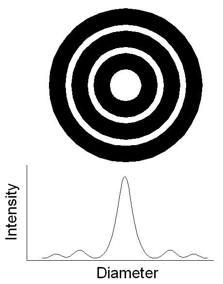
66 Diffraction Diffraction is caused by the interference of light waves with the aperture. As a result, an object point will appear as a small disc surrounded by a number of dark and bright rings. The radius of the central disc (r) can be computed as follows: r = 1.22 (f/d) where: f d is the wavelength of the light, is the focal length, and is the diameter of the aperture
67 Diffraction 67
68 Diffraction If two discs are to be moved towards each other, a point will be reached at which the two discs will no longer be identified as two separate objects. This is the case when the two objects are separated by the radius of one disc. The reciprocal of the disc radius is a measure of the resolving power of the lens system (optical resolution). Optical Resolution 1/ r 1 lines 1.22 ( f / d ) / mm 68
69 Diffraction r 69
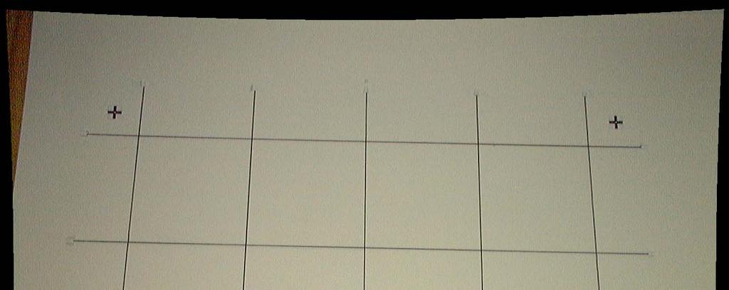
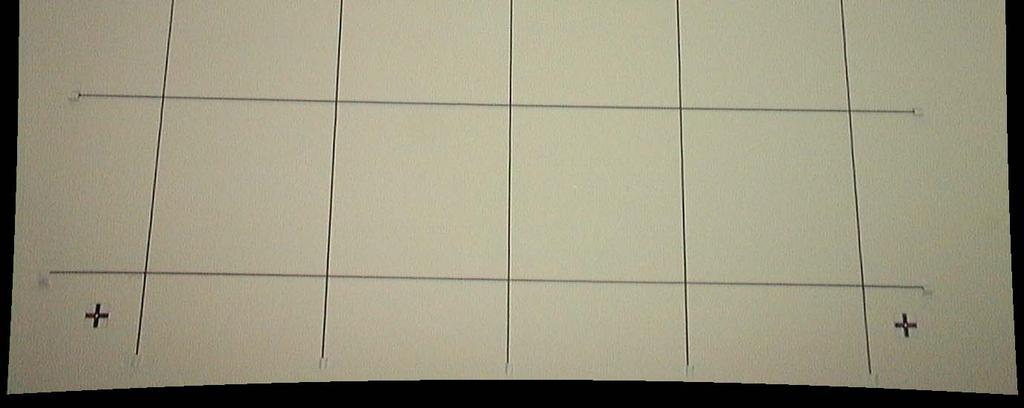
70 Resolving Power of an Imaging system Resolution is the ability of the system to identify nearby objects as separate entities. We want to establish a quantitative measure of the capability of our imaging system (camera and film) to image neighboring points or lines as separate entities. The resolution is measured in line-pairs per mm using resolution test chart. 70

71 Resolution Test Chart 71
72 Resolving Power of an Imaging system Factors that affect the resolving power include: Lens aberrations, Depth of field, Depth of focus, Diffraction, Film material or CCD/CMOS array, and Motion blur. 72
73 Depth of Field 73
74 Depth of Field The distance in the object space within which the object point can be moved and still be in acceptable focus. A N p A q A a c A F A a f Depth of field Image plane for object point A a N Circle of confusion same size at both apertures A c 74
75 Depth of Focus 75
76 Depth of Focus Depth of focus is the distance in front or behind the plane of best focus for a given object distance where the image is still in acceptable focus. Image plane d d p q d d Circle of confusion same size at both apertures Image plane 76
77 Factors Affecting Depth of Field/Depth of Focus The focal length The object distance The diameter of the aperture stop The smaller the aperture the larger the depth of field and focus. The radius of the acceptable circle of confusion 77
78 Motion Blur During the exposure of the photograph, the camera shutter remains open for a short time (dt) while the aircraft is still flying at a velocity (V). This causes a blur (motion blur) in the captured image. The magnitude of the motion blur depends on: The shutter opening time/shutter speed (dt), The velocity of the aircraft (V), The flying height (h), and The camera constant principal distance (c). 78
79 Motion Blur a 1 a 1 a 2 o 1 o 2 A 79
80 Motion Blur a dr a` c O O` V dt h dr / c = V * dt / h dr = V * dt * c / h A 80
81 Motion Blur To avoid motion blur, some photogrammetric cameras have a mechanism that causes the film to advance forward in the flight direction during the exposure time. The advancement magnitude should be exactly (dr). This advancement is known as the image motion compensation. 81
82 Summary In this chapter, we covered the following topics: Basics of geometric optics Factors affecting the precision of the final image coordinate measurements: Aberrations, diffraction, depth of field, depth of focus, and motion blur Resolving power of the imaging system Factors affecting the accuracy of the final image coordinate measurements: Radial and de-centering lens distortion 82
OPTICAL SYSTEMS OBJECTIVES
 101 L7 OPTICAL SYSTEMS OBJECTIVES Aims Your aim here should be to acquire a working knowledge of the basic components of optical systems and understand their purpose, function and limitations in terms
Performance Factors. Technical Assistance. Fundamental Optics
 Performance Factors After paraxial formulas have been used to select values for component focal length(s) and diameter(s), the final step is to select actual lenses. As in any engineering problem, this
Geometric optics & aberrations
 Geometric optics & aberrations Department of Astrophysical Sciences University AST 542 http://www.northerneye.co.uk/ Outline Introduction: Optics in astronomy Basics of geometric optics Paraxial approximation
Waves & Oscillations
 Physics 42200 Waves & Oscillations Lecture 33 Geometric Optics Spring 2013 Semester Matthew Jones Aberrations We have continued to make approximations: Paraxial rays Spherical lenses Index of refraction
Lecture 4: Geometrical Optics 2. Optical Systems. Images and Pupils. Rays. Wavefronts. Aberrations. Outline
 Lecture 4: Geometrical Optics 2 Outline 1 Optical Systems 2 Images and Pupils 3 Rays 4 Wavefronts 5 Aberrations Christoph U. Keller, Leiden University, keller@strw.leidenuniv.nl Lecture 4: Geometrical
Applied Optics. , Physics Department (Room #36-401) , ,
 , ,") Applied Optics Professor, Physics Department (Room #36-401) 2290-0923, 019-539-0923, shsong@hanyang.ac.kr Office Hours Mondays 15:00-16:30, Wednesdays 15:00-16:30 TA (Ph.D. student, Room #36-415) 2290-0921,
Applied Optics Professor, Physics Department (Room #36-401) 2290-0923, 019-539-0923, shsong@hanyang.ac.kr Office Hours Mondays 15:00-16:30, Wednesdays 15:00-16:30 TA (Ph.D. student, Room #36-415) 2290-0921,
Chapter 18 Optical Elements
 Chapter 18 Optical Elements GOALS When you have mastered the content of this chapter, you will be able to achieve the following goals: Definitions Define each of the following terms and use it in an operational
Lecture 2: Geometrical Optics. Geometrical Approximation. Lenses. Mirrors. Optical Systems. Images and Pupils. Aberrations.
 Lecture 2: Geometrical Optics Outline 1 Geometrical Approximation 2 Lenses 3 Mirrors 4 Optical Systems 5 Images and Pupils 6 Aberrations Christoph U. Keller, Leiden Observatory, keller@strw.leidenuniv.nl
 Light: Reflection and Refraction Light Reflection of Light by Plane Mirror Reflection of Light by Spherical Mirror Formation of Image by Mirror Sign Convention & Mirror Formula Refraction of light Through
Laboratory experiment aberrations
 Laboratory experiment aberrations Obligatory laboratory experiment on course in Optical design, SK2330/SK3330, KTH. Date Name Pass Objective This laboratory experiment is intended to demonstrate the most
Ch 24. Geometric Optics
 text concept Ch 24. Geometric Optics Fig. 24 3 A point source of light P and its image P, in a plane mirror. Angle of incidence =angle of reflection. text. Fig. 24 4 The blue dashed line through object
Big League Cryogenics and Vacuum The LHC at CERN
 Big League Cryogenics and Vacuum The LHC at CERN A typical astronomical instrument must maintain about one cubic meter at a pressure of
Image Formation. Light from distant things. Geometrical optics. Pinhole camera. Chapter 36
 Light from distant things Chapter 36 We learn about a distant thing from the light it generates or redirects. The lenses in our eyes create images of objects our brains can process. This chapter concerns
Lens Principal and Nodal Points
 Lens Principal and Nodal Points Douglas A. Kerr, P.E. Issue 3 January 21, 2004 ABSTRACT In discussions of photographic lenses, we often hear of the importance of the principal points and nodal points of
Chapters 1-3. Chapter 1: Introduction and applications of photogrammetry Chapter 2: Electro-magnetic radiation. Chapter 3: Basic optics
 Chapters 1-3 Chapter 1: Introduction and applications of photogrammetry Chapter 2: Electro-magnetic radiation Radiation sources Classification of remote sensing systems (passive & active) Electromagnetic
CHAPTER 33 ABERRATION CURVES IN LENS DESIGN
 CHAPTER 33 ABERRATION CURVES IN LENS DESIGN Donald C. O Shea Georgia Institute of Technology Center for Optical Science and Engineering and School of Physics Atlanta, Georgia Michael E. Harrigan Eastman
Chapters 1-3. Chapter 1: Introduction and applications of photogrammetry Chapter 2: Electro-magnetic radiation. Chapter 3: Basic optics
 Chapters 1-3 Chapter 1: Introduction and applications of photogrammetry Chapter 2: Electro-magnetic radiation Radiation sources Classification of remote sensing systems (passive & active) Electromagnetic
The optical analysis of the proposed Schmidt camera design.
 The optical analysis of the proposed Schmidt camera design. M. Hrabovsky, M. Palatka, P. Schovanek Joint Laboratory of Optics of Palacky University and Institute of Physics of the Academy of Sciences of
INTRODUCTION THIN LENSES. Introduction. given by the paraxial refraction equation derived last lecture: Thin lenses (19.1) = 1. Double-lens systems
 = 1. Double-lens systems") Chapter 9 OPTICAL INSTRUMENTS Introduction Thin lenses Double-lens systems Aberrations Camera Human eye Compound microscope Summary INTRODUCTION Knowledge of geometrical optics, diffraction and interference,
Chapter 9 OPTICAL INSTRUMENTS Introduction Thin lenses Double-lens systems Aberrations Camera Human eye Compound microscope Summary INTRODUCTION Knowledge of geometrical optics, diffraction and interference,
Chapter 29/30. Wave Fronts and Rays. Refraction of Sound. Dispersion in a Prism. Index of Refraction. Refraction and Lenses
 Chapter 29/30 Refraction and Lenses Refraction Refraction the bending of waves as they pass from one medium into another. Caused by a change in the average speed of light. Analogy A car that drives off
Introduction. Geometrical Optics. Milton Katz State University of New York. VfeWorld Scientific New Jersey London Sine Singapore Hong Kong
 Introduction to Geometrical Optics Milton Katz State University of New York VfeWorld Scientific «New Jersey London Sine Singapore Hong Kong TABLE OF CONTENTS PREFACE ACKNOWLEDGMENTS xiii xiv CHAPTER 1:
IMAGE FORMATION. Light source properties. Sensor characteristics Surface. Surface reflectance properties. Optics
 IMAGE FORMATION Light source properties Sensor characteristics Surface Exposure shape Optics Surface reflectance properties ANALOG IMAGES An image can be understood as a 2D light intensity function f(x,y)
Waves & Oscillations
 Physics 42200 Waves & Oscillations Lecture 27 Geometric Optics Spring 205 Semester Matthew Jones Sign Conventions > + = Convex surface: is positive for objects on the incident-light side is positive for
E X P E R I M E N T 12
 E X P E R I M E N T 12 Mirrors and Lenses Produced by the Physics Staff at Collin College Copyright Collin College Physics Department. All Rights Reserved. University Physics II, Exp 12: Mirrors and Lenses
Lecture 3: Geometrical Optics 1. Spherical Waves. From Waves to Rays. Lenses. Chromatic Aberrations. Mirrors. Outline
 Lecture 3: Geometrical Optics 1 Outline 1 Spherical Waves 2 From Waves to Rays 3 Lenses 4 Chromatic Aberrations 5 Mirrors Christoph U. Keller, Leiden Observatory, keller@strw.leidenuniv.nl Lecture 3: Geometrical
25 cm. 60 cm. 50 cm. 40 cm.
 Geometrical Optics 7. The image formed by a plane mirror is: (a) Real. (b) Virtual. (c) Erect and of equal size. (d) Laterally inverted. (e) B, c, and d. (f) A, b and c. 8. A real image is that: (a) Which
LENSES. INEL 6088 Computer Vision
 LENSES INEL 6088 Computer Vision Digital camera A digital camera replaces film with a sensor array Each cell in the array is a Charge Coupled Device light-sensitive diode that converts photons to electrons
Lenses. Overview. Terminology. The pinhole camera. Pinhole camera Lenses Principles of operation Limitations
 Overview Pinhole camera Principles of operation Limitations 1 Terminology The pinhole camera The first camera - camera obscura - known to Aristotle. In 3D, we can visualize the blur induced by the pinhole
Algebra Based Physics. Reflection. Slide 1 / 66 Slide 2 / 66. Slide 3 / 66. Slide 4 / 66. Slide 5 / 66. Slide 6 / 66.
 Slide 1 / 66 Slide 2 / 66 Algebra Based Physics Geometric Optics 2015-12-01 www.njctl.org Slide 3 / 66 Slide 4 / 66 Table of ontents lick on the topic to go to that section Reflection Refraction and Snell's
Lens Design I. Lecture 3: Properties of optical systems II Herbert Gross. Summer term
 Lens Design I Lecture 3: Properties of optical systems II 205-04-8 Herbert Gross Summer term 206 www.iap.uni-jena.de 2 Preliminary Schedule 04.04. Basics 2.04. Properties of optical systrems I 3 8.04.
Chapter 34 Geometric Optics (also known as Ray Optics) by C.-R. Hu
 by C.-R. Hu") Chapter 34 Geometric Optics (also known as Ray Optics) by C.-R. Hu 1. Principles of image formation by mirrors (1a) When all length scales of objects, gaps, and holes are much larger than the wavelength
Chapter 34 Geometric Optics (also known as Ray Optics) by C.-R. Hu 1. Principles of image formation by mirrors (1a) When all length scales of objects, gaps, and holes are much larger than the wavelength
IMAGE SENSOR SOLUTIONS. KAC-96-1/5" Lens Kit. KODAK KAC-96-1/5" Lens Kit. for use with the KODAK CMOS Image Sensors. November 2004 Revision 2
 KODAK for use with the KODAK CMOS Image Sensors November 2004 Revision 2 1.1 Introduction Choosing the right lens is a critical aspect of designing an imaging system. Typically the trade off between image
Assignment X Light. Reflection and refraction of light. (a) Angle of incidence (b) Angle of reflection (c) principle axis
 Angle of incidence (b) Angle of reflection (c) principle axis") Assignment X Light Reflection of Light: Reflection and refraction of light. 1. What is light and define the duality of light? 2. Write five characteristics of light. 3. Explain the following terms (a)
Assignment X Light Reflection of Light: Reflection and refraction of light. 1. What is light and define the duality of light? 2. Write five characteristics of light. 3. Explain the following terms (a)
Chapter 36. Image Formation
 Chapter 36 Image Formation Image of Formation Images can result when light rays encounter flat or curved surfaces between two media. Images can be formed either by reflection or refraction due to these
Chapter 36. Image Formation
 Chapter 36 Image Formation Notation for Mirrors and Lenses The object distance is the distance from the object to the mirror or lens Denoted by p The image distance is the distance from the image to the
Mirrors and Lenses. Images can be formed by reflection from mirrors. Images can be formed by refraction through lenses.
 Mirrors and Lenses Images can be formed by reflection from mirrors. Images can be formed by refraction through lenses. Notation for Mirrors and Lenses The object distance is the distance from the object
Opti 415/515. Introduction to Optical Systems. Copyright 2009, William P. Kuhn
 Opti 415/515 Introduction to Optical Systems 1 Optical Systems Manipulate light to form an image on a detector. Point source microscope Hubble telescope (NASA) 2 Fundamental System Requirements Application
PHYS 202 OUTLINE FOR PART III LIGHT & OPTICS
 PHYS 202 OUTLINE FOR PART III LIGHT & OPTICS Electromagnetic Waves A. Electromagnetic waves S-23,24 1. speed of waves = 1/( o o ) ½ = 3 x 10 8 m/s = c 2. waves and frequency: the spectrum (a) radio red
always positive for virtual image
 Point to be remembered: sign convention for Spherical mirror Object height, h = always positive Always +ve for virtual image Image height h = Always ve for real image. Object distance from pole (u) = always
Lens Design I. Lecture 3: Properties of optical systems II Herbert Gross. Summer term
 Lens Design I Lecture 3: Properties of optical systems II 207-04-20 Herbert Gross Summer term 207 www.iap.uni-jena.de 2 Preliminary Schedule - Lens Design I 207 06.04. Basics 2 3.04. Properties of optical
CHAPTER 1 Optical Aberrations
 CHAPTER 1 Optical Aberrations 1.1 INTRODUCTION This chapter starts with the concepts of aperture stop and entrance and exit pupils of an optical imaging system. Certain special rays, such as the chief
ECEN 4606, UNDERGRADUATE OPTICS LAB
 ECEN 4606, UNDERGRADUATE OPTICS LAB Lab 2: Imaging 1 the Telescope Original Version: Prof. McLeod SUMMARY: In this lab you will become familiar with the use of one or more lenses to create images of distant
ECEG105/ECEU646 Optics for Engineers Course Notes Part 4: Apertures, Aberrations Prof. Charles A. DiMarzio Northeastern University Fall 2008
 ECEG105/ECEU646 Optics for Engineers Course Notes Part 4: Apertures, Aberrations Prof. Charles A. DiMarzio Northeastern University Fall 2008 July 2003+ Chuck DiMarzio, Northeastern University 11270-04-1
Geometry of Aerial Photographs
 Geometry of Aerial Photographs Aerial Cameras Aerial cameras must be (details in lectures): Geometrically stable Have fast and efficient shutters Have high geometric and optical quality lenses They can
 Telecentric Imaging Object space telecentricity stop source: edmund optics The 5 classical Seidel Aberrations First order aberrations Spherical Aberration (~r 4 ) Origin: different focal lengths for different
ii) When light falls on objects, it reflects the light and when the reflected light reaches our eyes then we see the objects.
 When light falls on objects, it reflects the light and when the reflected light reaches our eyes then we see the objects.") Light i) Light is a form of energy which helps us to see objects. ii) When light falls on objects, it reflects the light and when the reflected light reaches our eyes then we see the objects. iii) Light
Light i) Light is a form of energy which helps us to see objects. ii) When light falls on objects, it reflects the light and when the reflected light reaches our eyes then we see the objects. iii) Light
Cardinal Points of an Optical System--and Other Basic Facts
 Cardinal Points of an Optical System--and Other Basic Facts The fundamental feature of any optical system is the aperture stop. Thus, the most fundamental optical system is the pinhole camera. The image
R.B.V.R.R. WOMEN S COLLEGE (AUTONOMOUS) Narayanaguda, Hyderabad.
 Narayanaguda, Hyderabad.") R.B.V.R.R. WOMEN S COLLEGE (AUTONOMOUS) Narayanaguda, Hyderabad. DEPARTMENT OF PHYSICS QUESTION BANK FOR SEMESTER III PAPER III OPTICS UNIT I: 1. MATRIX METHODS IN PARAXIAL OPTICS 2. ABERATIONS UNIT II
R.B.V.R.R. WOMEN S COLLEGE (AUTONOMOUS) Narayanaguda, Hyderabad. DEPARTMENT OF PHYSICS QUESTION BANK FOR SEMESTER III PAPER III OPTICS UNIT I: 1. MATRIX METHODS IN PARAXIAL OPTICS 2. ABERATIONS UNIT II
LIGHT REFLECTION AND REFRACTION
 LIGHT REFLECTION AND REFRACTION REFLECTION OF LIGHT A highly polished surface, such as a mirror, reflects most of the light falling on it. Laws of Reflection: (i) The angle of incidence is equal to the
Lenses, exposure, and (de)focus
focus") Lenses, exposure, and (de)focus http://graphics.cs.cmu.edu/courses/15-463 15-463, 15-663, 15-862 Computational Photography Fall 2017, Lecture 15 Course announcements Homework 4 is out. - Due October 26
Lenses, exposure, and (de)focus http://graphics.cs.cmu.edu/courses/15-463 15-463, 15-663, 15-862 Computational Photography Fall 2017, Lecture 15 Course announcements Homework 4 is out. - Due October 26
CS 443: Imaging and Multimedia Cameras and Lenses
 CS 443: Imaging and Multimedia Cameras and Lenses Spring 2008 Ahmed Elgammal Dept of Computer Science Rutgers University Outlines Cameras and lenses! 1 They are formed by the projection of 3D objects.
TSBB09 Image Sensors 2018-HT2. Image Formation Part 1
 TSBB09 Image Sensors 2018-HT2 Image Formation Part 1 Basic physics Electromagnetic radiation consists of electromagnetic waves With energy That propagate through space The waves consist of transversal
CH. 23 Mirrors and Lenses HW# 6, 7, 9, 11, 13, 21, 25, 31, 33, 35
 CH. 23 Mirrors and Lenses HW# 6, 7, 9, 11, 13, 21, 25, 31, 33, 35 Mirrors Rays of light reflect off of mirrors, and where the reflected rays either intersect or appear to originate from, will be the location
Chapter 26. The Refraction of Light: Lenses and Optical Instruments
 Chapter 26 The Refraction of Light: Lenses and Optical Instruments 26.1 The Index of Refraction Light travels through a vacuum at a speed c=3. 00 10 8 m/ s Light travels through materials at a speed less
Introduction to Optical Modeling. Friedrich-Schiller-University Jena Institute of Applied Physics. Lecturer: Prof. U.D. Zeitner
 Introduction to Optical Modeling Friedrich-Schiller-University Jena Institute of Applied Physics Lecturer: Prof. U.D. Zeitner The Nature of Light Fundamental Question: What is Light? Newton Huygens / Maxwell
Chapter Ray and Wave Optics
 109 Chapter Ray and Wave Optics 1. An astronomical telescope has a large aperture to [2002] reduce spherical aberration have high resolution increase span of observation have low dispersion. 2. If two
Chapter 25 Optical Instruments
 Chapter 25 Optical Instruments Units of Chapter 25 Cameras, Film, and Digital The Human Eye; Corrective Lenses Magnifying Glass Telescopes Compound Microscope Aberrations of Lenses and Mirrors Limits of
PHYSICS FOR THE IB DIPLOMA CAMBRIDGE UNIVERSITY PRESS
 Option C Imaging C Introduction to imaging Learning objectives In this section we discuss the formation of images by lenses and mirrors. We will learn how to construct images graphically as well as algebraically.
UNIVERSITY OF NAIROBI COLLEGE OF EDUCATION AND EXTERNAL STUDIES
 UNIVERSITY OF NAIROBI COLLEGE OF EDUCATION AND EXTERNAL STUDIES COURSE TITLE: BED (SCIENCE) UNIT TITLE: WAVES AND OPTICS UNIT CODE: SPH 103 UNIT AUTHOR: PROF. R.O. GENGA DEPARTMENT OF PHYSICS UNIVERSITY
LIGHT REFLECTION AND REFRACTION
 LIGHT REFLECTION AND REFRACTION 1. List four properties of the image formed by a plane mirror. Properties of image formed by a plane mirror: 1. It is always virtual and erect. 2. Its size is equal to that
Algebra Based Physics. Reflection. Slide 1 / 66 Slide 2 / 66. Slide 3 / 66. Slide 4 / 66. Slide 5 / 66. Slide 6 / 66.
 Slide 1 / 66 Slide 2 / 66 lgebra ased Physics Geometric Optics 2015-12-01 www.njctl.org Slide 3 / 66 Slide 4 / 66 Table of ontents lick on the topic to go to that section Reflection Refraction and Snell's
Opto Engineering S.r.l.
 TUTORIAL #1 Telecentric Lenses: basic information and working principles On line dimensional control is one of the most challenging and difficult applications of vision systems. On the other hand, besides
Notes from Lens Lecture with Graham Reed
 Notes from Lens Lecture with Graham Reed Light is refracted when in travels between different substances, air to glass for example. Light of different wave lengths are refracted by different amounts. Wave
This experiment is under development and thus we appreciate any and all comments as we design an interesting and achievable set of goals.
 Experiment 7 Geometrical Optics You will be introduced to ray optics and image formation in this experiment. We will use the optical rail, lenses, and the camera body to quantify image formation and magnification;
30 Lenses. Lenses change the paths of light.
 Lenses change the paths of light. A light ray bends as it enters glass and bends again as it leaves. Light passing through glass of a certain shape can form an image that appears larger, smaller, closer,
Reflection! Reflection and Virtual Image!
 1/30/14 Reflection - wave hits non-absorptive surface surface of a smooth water pool - incident vs. reflected wave law of reflection - concept for all electromagnetic waves - wave theory: reflected back
Section 3. Imaging With A Thin Lens
 3-1 Section 3 Imaging With A Thin Lens Object at Infinity An object at infinity produces a set of collimated set of rays entering the optical system. Consider the rays from a finite object located on the
Name. Light Chapter Summary Cont d. Refraction
 Page 1 of 17 Physics Week 12(Sem. 2) Name Light Chapter Summary Cont d with a smaller index of refraction to a material with a larger index of refraction, the light refracts towards the normal line. Also,
CHAPTER TWO METALLOGRAPHY & MICROSCOPY
 CHAPTER TWO METALLOGRAPHY & MICROSCOPY 1. INTRODUCTION: Materials characterisation has two main aspects: Accurately measuring the physical, mechanical and chemical properties of materials Accurately measuring
Chapter 23. Light Geometric Optics
 Chapter 23. Light Geometric Optics There are 3 basic ways to gather light and focus it to make an image. Pinhole - Simple geometry Mirror - Reflection Lens - Refraction Pinhole Camera Image Formation (the
Geometrical Optics. Have you ever entered an unfamiliar room in which one wall was covered with a
 Return to Table of Contents HAPTER24 C. Geometrical Optics A mirror now used in the Hubble space telescope Have you ever entered an unfamiliar room in which one wall was covered with a mirror and thought
Camera Simulation. References. Photography, B. London and J. Upton Optics in Photography, R. Kingslake The Camera, The Negative, The Print, A.
 Camera Simulation Effect Cause Field of view Film size, focal length Depth of field Aperture, focal length Exposure Film speed, aperture, shutter Motion blur Shutter References Photography, B. London and
Exam Preparation Guide Geometrical optics (TN3313)
") Exam Preparation Guide Geometrical optics (TN3313) Lectures: September - December 2001 Version of 21.12.2001 When preparing for the exam, check on Blackboard for a possible newer version of this guide.
Exam Preparation Guide Geometrical optics (TN3313) Lectures: September - December 2001 Version of 21.12.2001 When preparing for the exam, check on Blackboard for a possible newer version of this guide.
Converging Lenses. Parallel rays are brought to a focus by a converging lens (one that is thicker in the center than it is at the edge).
.") Chapter 30: Lenses Types of Lenses Piece of glass or transparent material that bends parallel rays of light so they cross and form an image Two types: Converging Diverging Converging Lenses Parallel rays
Chapter 30: Lenses Types of Lenses Piece of glass or transparent material that bends parallel rays of light so they cross and form an image Two types: Converging Diverging Converging Lenses Parallel rays
Chapter 23. Mirrors and Lenses
 Chapter 23 Mirrors and Lenses Notation for Mirrors and Lenses The object distance is the distance from the object to the mirror or lens Denoted by p The image distance is the distance from the image to
Optical Systems: Pinhole Camera Pinhole camera: simple hole in a box: Called Camera Obscura Aristotle discussed, Al-Hazen analyzed in Book of Optics
 Optical Systems: Pinhole Camera Pinhole camera: simple hole in a box: Called Camera Obscura Aristotle discussed, Al-Hazen analyzed in Book of Optics 1011CE Restricts rays: acts as a single lens: inverts
VISUAL PHYSICS ONLINE DEPTH STUDY: ELECTRON MICROSCOPES
 VISUAL PHYSICS ONLINE DEPTH STUDY: ELECTRON MICROSCOPES Shortly after the experimental confirmation of the wave properties of the electron, it was suggested that the electron could be used to examine objects
Department of Physics & Astronomy Undergraduate Labs. Thin Lenses
 Thin Lenses Reflection and Refraction When light passes from one medium to another, part of the light is reflected and the rest is transmitted. Light rays that are transmitted undergo refraction (bending)
Fundamental Paraxial Equation for Thin Lenses
 THIN LENSES Fundamental Paraxial Equation for Thin Lenses A thin lens is one for which thickness is "negligibly" small and may be ignored. Thin lenses are the most important optical entity in ophthalmic
Lens Design I Seminar 1
 Xiang Lu, Ralf Hambach Friedrich Schiller University Jena Institute of Applied Physics Albert-Einstein-Str 15 07745 Jena Lens Design I Seminar 1 Warm-Up (20min) Setup a single, symmetric, biconvex lens
Chapter 23. Mirrors and Lenses
 Chapter 23 Mirrors and Lenses Mirrors and Lenses The development of mirrors and lenses aided the progress of science. It led to the microscopes and telescopes. Allowed the study of objects from microbes
Chapter 25. Optical Instruments
 Chapter 25 Optical Instruments Optical Instruments Analysis generally involves the laws of reflection and refraction Analysis uses the procedures of geometric optics To explain certain phenomena, the wave
BHARATIYA VIDYA BHAVAN S V M PUBLIC SCHOOL, VADODARA QUESTION BANK
 BHARATIYA VIDYA BHAVAN S V M PUBLIC SCHOOL, VADODARA QUESTION BANK Ch Light : Reflection and Refraction One mark questions Q1 Q3 What happens when a ray of light falls normally on the surface of a plane
R 1 R 2 R 3. t 1 t 2. n 1 n 2
 MASSACHUSETTS INSTITUTE OF TECHNOLOGY 2.71/2.710 Optics Spring 14 Problem Set #2 Posted Feb. 19, 2014 Due Wed Feb. 26, 2014 1. (modified from Pedrotti 18-9) A positive thin lens of focal length 10cm is
GEOMETRICAL OPTICS AND OPTICAL DESIGN
 GEOMETRICAL OPTICS AND OPTICAL DESIGN Pantazis Mouroulis Associate Professor Center for Imaging Science Rochester Institute of Technology John Macdonald Senior Lecturer Physics Department University of
Lecture 26. PHY 112: Light, Color and Vision. Finalities. Final: Thursday May 19, 2:15 to 4:45 pm. Prof. Clark McGrew Physics D 134
 PHY 112: Light, Color and Vision Lecture 26 Prof. Clark McGrew Physics D 134 Finalities Final: Thursday May 19, 2:15 to 4:45 pm ESS 079 (this room) Lecture 26 PHY 112 Lecture 1 Introductory Chapters Chapters
Chapter 34: Geometric Optics
 Chapter 34: Geometric Optics It is all about images How we can make different kinds of images using optical devices Optical device example: mirror, a piece of glass, telescope, microscope, kaleidoscope,
COURSE NAME: PHOTOGRAPHY AND AUDIO VISUAL PRODUCTION (VOCATIONAL) FOR UNDER GRADUATE (FIRST YEAR)
 FOR UNDER GRADUATE (FIRST YEAR)") COURSE NAME: PHOTOGRAPHY AND AUDIO VISUAL PRODUCTION (VOCATIONAL) FOR UNDER GRADUATE (FIRST YEAR) PAPER TITLE: BASIC PHOTOGRAPHIC UNIT - 3 : SIMPLE LENS TOPIC: LENS PROPERTIES AND DEFECTS OBJECTIVES By
COURSE NAME: PHOTOGRAPHY AND AUDIO VISUAL PRODUCTION (VOCATIONAL) FOR UNDER GRADUATE (FIRST YEAR) PAPER TITLE: BASIC PHOTOGRAPHIC UNIT - 3 : SIMPLE LENS TOPIC: LENS PROPERTIES AND DEFECTS OBJECTIVES By
PHYSICS. Chapter 35 Lecture FOR SCIENTISTS AND ENGINEERS A STRATEGIC APPROACH 4/E RANDALL D. KNIGHT
 PHYSICS FOR SCIENTISTS AND ENGINEERS A STRATEGIC APPROACH 4/E Chapter 35 Lecture RANDALL D. KNIGHT Chapter 35 Optical Instruments IN THIS CHAPTER, you will learn about some common optical instruments and
PHYS 160 Astronomy. When analyzing light s behavior in a mirror or lens, it is helpful to use a technique called ray tracing.
 Optics Introduction In this lab, we will be exploring several properties of light including diffraction, reflection, geometric optics, and interference. There are two sections to this lab and they may
[ Summary. 3i = 1* 6i = 4J;
 the projections at angle 2. We calculate the difference between the measured projections at angle 2 (6 and 14) and the projections based on the previous esti mate (top row: 2>\ + 6\ = 10; same for bottom
1) An electromagnetic wave is a result of electric and magnetic fields acting together. T 1)
 An electromagnetic wave is a result of electric and magnetic fields acting together. T 1)") Exam 3 Review Name TRUE/FALSE. Write 'T' if the statement is true and 'F' if the statement is false. 1) An electromagnetic wave is a result of electric and magnetic fields acting together. T 1) 2) Electromagnetic
Exam 3 Review Name TRUE/FALSE. Write 'T' if the statement is true and 'F' if the statement is false. 1) An electromagnetic wave is a result of electric and magnetic fields acting together. T 1) 2) Electromagnetic
SUBJECT: PHYSICS. Use and Succeed.
 SUBJECT: PHYSICS I hope this collection of questions will help to test your preparation level and useful to recall the concepts in different areas of all the chapters. Use and Succeed. Navaneethakrishnan.V
Image Formation and Camera Design
 Image Formation and Camera Design Spring 2003 CMSC 426 Jan Neumann 2/20/03 Light is all around us! From London & Upton, Photography Conventional camera design... Ken Kay, 1969 in Light & Film, TimeLife
GEOMETRICAL OPTICS Practical 1. Part I. BASIC ELEMENTS AND METHODS FOR CHARACTERIZATION OF OPTICAL SYSTEMS
 GEOMETRICAL OPTICS Practical 1. Part I. BASIC ELEMENTS AND METHODS FOR CHARACTERIZATION OF OPTICAL SYSTEMS Equipment and accessories: an optical bench with a scale, an incandescent lamp, matte, a set of
10.2 Images Formed by Lenses SUMMARY. Refraction in Lenses. Section 10.1 Questions
 10.2 SUMMARY Refraction in Lenses Converging lenses bring parallel rays together after they are refracted. Diverging lenses cause parallel rays to move apart after they are refracted. Rays are refracted
EE119 Introduction to Optical Engineering Spring 2002 Final Exam. Name:
 EE119 Introduction to Optical Engineering Spring 2002 Final Exam Name: SID: CLOSED BOOK. FOUR 8 1/2 X 11 SHEETS OF NOTES, AND SCIENTIFIC POCKET CALCULATOR PERMITTED. TIME ALLOTTED: 180 MINUTES Fundamental
EE-527: MicroFabrication
 EE-57: MicroFabrication Exposure and Imaging Photons white light Hg arc lamp filtered Hg arc lamp excimer laser x-rays from synchrotron Electrons Ions Exposure Sources focused electron beam direct write
Introduction. Strand F Unit 3: Optics. Learning Objectives. Introduction. At the end of this unit you should be able to;
 Learning Objectives At the end of this unit you should be able to; Identify converging and diverging lenses from their curvature Construct ray diagrams for converging and diverging lenses in order to locate