MasterCAM for Dresser Valet
|
|
|
- Tobias Davidson
- 5 years ago
- Views:
Transcription


1 MasterCAM for Dresser Valet Check to make sure the nethasp is working/turned on to network. Go to ALL APPs/Mastercam x8/nethasp

2 After the computer reads the nethasp, these programs should show up. If not ask your instructor. Open the MasterCAM application, it should look something like below.
.")
3 First thing is to figure out what you are making.using the measurements from your plans or your adjusted measurements from your plans, you will draw your geometry (geometry is a generic term for lines, arcs, etc. in a computer drawing program). Personally I just draw on the piece of wood that is going to be cut and plot the points needed to draw the geometry. This geometry must be drawn in the 1 st quadrant of the coordinate system, so positive x and y. The placement of the geometry matters since we will later be cutting out the part using the CNC Router. The CNC Router uses the coordinates from where you draw the geometry. F9 will display the x/y axis such as: Draw starting at the origin (0,0) To start a project, we need to set our specific CNC router and set up the stock sizes. MasterCAM can write NC code for different manufacturers of CNC equipment. Our router is a Forest Scientific Velosity 3 axis mill. MasterCAM will write the correct type of code as long as we pick the correct machine definition. This is a critical first step, without the machine definition, the CNC router will crash.litterly the tool bit will dive into the table top. Your instructor will help you load the machine definition when you go to the cnc router, for the time being set the machine definition to default mill. Goto Machine Type/Mill/Default.

.")
4 The result: there should be one machine group that says Properties Default Mill, if there is other Machine Groups, right-click and delete them. Stock Setup The Toolpaths Operations Manager is the tool palette that is docked on the left of the screen. This displays all the specific information about the tool paths (what the CNC router will cut). Expand the properties tab in the operations manager. Then click on stock setup.

5 Setup the stock: Enter the measurements for your piece, I m putting in 11 (y), 16 (x),.75(z) for my measurements for the project. I m not including the extra stock for the screws to hold it down to the router. Set the stock origin by clicking on this corner. Check Display Leave these x,y,z s at 0 Click the Green Check Mark (OK) After you click ok in the stock setup, you should see a red dashed rectangle that represents your stock. Zoom in or out so that you see the whole piece, like below.
6 Entering Geometry It s time to start drawing some geometry, so figure out what pockets you want to cut on your piece, and you will need the corresponding coordinates to draw the geometry. I m going to leave 1.5 margin around the work piece so that I know that the screws will not intersect a pocket when that project is assembled. Also, I will leave 1 between the pockets so everything looks symmetrical. I m just going to do 3 rectangles for the shapes of my pockets, but you can do what you like as long as it looks good and is symmetrical/balanced. To draw a rectangle, we need the coordinates of the opposite corners of each rectangle. When you have the coordinates written down then you are ready to go the rectangle tool, then we can just type in the two coordinates for the corners of each rectangle. Once prompted, type in (1.5,1.5) for the first corner then hit enter, and your second coordinate for the second corner, I m going to use (7.5,4) for the second and hit enter. MasterCAM will sketch it first, then you have to hit enter again to draw it.


7 Result: Now you can keep creating geometry in this method. You might want to draw out you shapes on graph paper or on your board first so you can keep the measurements correct. Here is my example. To complete this, you just need to coordinates of opposite corners of the rectangle. If you want to include a circle or other shape that is fine. They are just drawn from a center point and the radius or diameter. Result:

8 Toolpaths: For 2D geometry such as we have, there are 2 main types of tool paths. The first one is a contour, and the second a pocket. In a contour toolpath, the tool bit will follow a path. The path can be one piece of geometry or multiple pieces of geometry linked together end to end. When the geometry is selected you must either pick the single option or the chaining option (multiple objects laid out end to end) before you select the geometry. We are going to complete pocket toolpaths. A pocket toolpath will make a cavity inside the selected geometry. We should be able to use one pocket toolpath and pick all the geometry to complete the cut correctly. When we select the geometry, we will use the chaining option, since the rectangles are really made from four lines each. To start the toolpaths, go to Toolpaths/Pocket.


9 Enter an appropriate name for the toolpath in this window Make sure the chaining option is selected then click on the geometry you want to drive the operation.

10 Click on the 3 chains (the 3 rectangles) one click should select all the sides of the rectangles. After the selection your screen should look like this, the green arrow should appear each time you click on a new chain. It may disappear then. Click ok, to end our selection.


11 Please enter the following information in the pocket toolpath parameters. Right- click in this white space


12 You may need to use a different tool depending on what you are doing and what tool is available. Ask your instructor.


13 You should now see the cutter/bit in this window. This is the bit we will use to cut the piece. Enter: Feed rate =100 Plunge rate = 30


14 Enter 0 for both stock to leave fields.

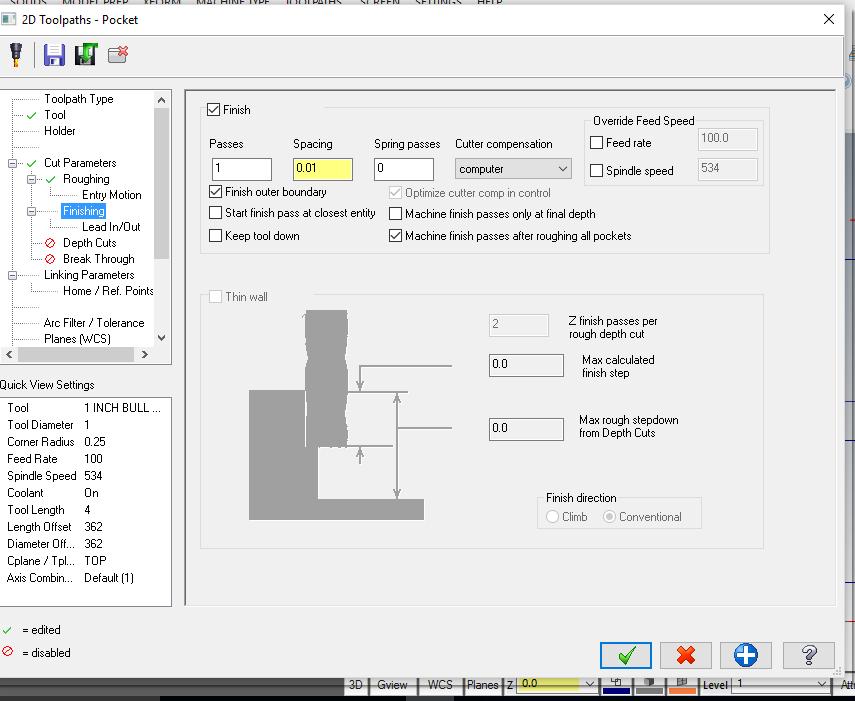
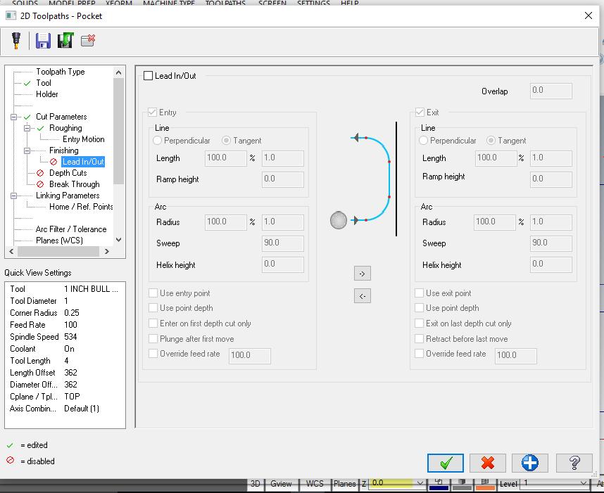
15 Just check this window, all the defaults should be correct. Just check this window, all the defaults should be correct.
16

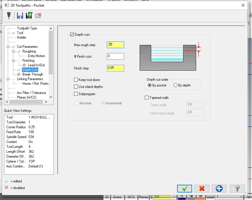
17 To set the depth of the cut, please enter the below values. In the Linking Parameters tab. Notice that all the values are Absolute and the depth is a -.5.
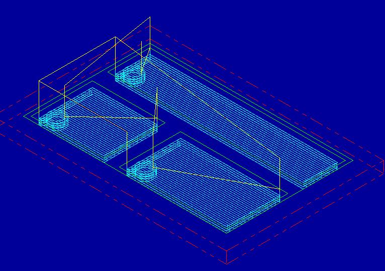
18 After you hit OK, you should see mastercam draw the toolpaths. The blue lines represent the center of the cutter when it is cutting material, and the yellow lines represent the center of the cutter when it moves between geometry.

19 To Verify your toolpath, go to an isometric view, zoom in/out, and pan the drawing so you see something such as below: Next click Verify

20 This will open up in a new window titled MasterCAM Simulator, and you can push the play button at the bottom of the window. It should see your part cut out virtually. Please show your instructor.
10 x 16 Cutting Board - Juice Groove in MasterCAM
 10 x 16 Cutting Board - Juice Groove in MasterCAM Check to make sure the nethasp is working/turned on to network. Go to ALL APPs/Mastercam x8/nethasp After the computer reads the nethasp, these programs
Box Tray Geometry in MasterCAM
 Box Tray Geometry in MasterCAM First thing is to figure out what you are making. The best way is to get graph paper and draw out the tray full size or draw the pockets right on your work piece. Then you
MasterCAM for Sculpted Bench
 MasterCAM for Sculpted Bench Check to make sure the nethasp is working/turned on to network. Go to ALL APPs/Mastercam x8/nethasp After the computer reads the nethasp, these programs should show up. If
Kerf Bent Clock Front Geometry in MasterCAM
 Kerf Bent Clock Front Geometry in MasterCAM Check to make sure the nethasp is working/turned on to network. Go to ALL APPs/Mastercam x8/nethasp After the computer reads the nethasp, these programs should
Kerf Bent Clock Front Geometry in MasterCAM. Open the MasterCAM application, it should look something like below.
 Kerf Bent Clock Front Geometry in MasterCAM Open the MasterCAM application, it should look something like below. First thing is to figure out what you are making.using the measurements from your plans,
Kerf Bent Clock Front Toolpaths in MasterCAM. Open the MasterCAM application and open your clock front geometry file.
 Kerf Bent Clock Front Toolpaths in MasterCAM Open the MasterCAM application and open your clock front geometry file. For 2D geometry such as we have, there are 2 main types of tool paths. The first one
for Solidworks TRAINING GUIDE LESSON-9-CAD
 for Solidworks TRAINING GUIDE LESSON-9-CAD Mastercam for SolidWorks Training Guide Objectives You will create the geometry for SolidWorks-Lesson-9 using SolidWorks 3D CAD software. You will be working
ENGI 7962 Mastercam Lab Mill 1
 ENGI 7962 Mastercam Lab Mill 1 Starting a Mastercam file: Once the SolidWorks models is complete (all sketches are Fully Defined), start up Mastercam and select File, Open, Files of Type, SolidWorks Files,
Flip for User Guide. Inches. When Reliability Matters
 Flip for User Guide Inches by When Reliability Matters Mastercam HSM Performance Pack Tutorial 1 Mastercam HSM Performance Pack Tutorial Tutorial I... 2 Getting started... 2 Tools used... 2 Roughing...
Flip for User Guide. Metric. When Reliability Matters
 Flip for User Guide Metric by When Reliability Matters Mastercam HSM Performance Pack Tutorial 1 Mastercam HSM Performance Pack Tutorial Tutorial I... 2 Getting started... 2 Tools used... 2 Roughing...
In this tutorial you will open a Dxf file and create the toolpath that cut the external of the part.
 Tutorial 2 - Open Dxf file and create the outside Contour toolpath. In this tutorial you will open a Dxf file and create the toolpath that cut the external of the part. Caution: CNC machines are potentially
Tutorial 4 - Open Dxf file and create multiple toolpaths (Contour, Pocket and Drill).
.") Tutorial 4 - Open Dxf file and create multiple toolpaths (Contour, Pocket and Drill). In this tutorial you will open a Dxf file and create the toolpath that cut the external of the part, another toolpath
Tutorial 4 - Open Dxf file and create multiple toolpaths (Contour, Pocket and Drill). In this tutorial you will open a Dxf file and create the toolpath that cut the external of the part, another toolpath
In this tutorial you will open a Dxf file and create the toolpath to remove the material contained in a closed profile.
 Tutorial 3 - Open Dxf file and create the Pocket toolpath. In this tutorial you will open a Dxf file and create the toolpath to remove the material contained in a closed profile. Caution: CNC machines
MadCAM 2.0: Drill Pattern Toolpath
 MadCAM 2.0: Drill Pattern Toolpath Digital Media Tutorial 2005-2006 MadCAM 2.0 can create a toolpath to drill holes directly into your material. The bit plunges in and out of the material without moving
Using Surfcam to Produce a Numeric Control (NC) Program Part #1 Surfcam Demonstration Version Use
 Program Part #1 Surfcam Demonstration Version Use") Using Surfcam to Produce a Numeric Control (NC) Program Part #1 Surfcam Demonstration Version Use An Introduction to the CAD/CAM Process Instructions for 3 Axis Programming Using the D&M CNC Milling Machine
Using Surfcam to Produce a Numeric Control (NC) Program Part #1 Surfcam Demonstration Version Use An Introduction to the CAD/CAM Process Instructions for 3 Axis Programming Using the D&M CNC Milling Machine
CAMWorks How To Create CNC G-Code for CO2 Dragsters
 Objective: In this chapter we will show how to mill out the axle holes for this CO2 Dragster from the left side. VI.1. Open the previously created file: Dragster axle hole 001.sldprt. VI.2. Select the
CNC: The Machine. Sullivan Fabrication Studio Version 5.1 (beta)
") CNC: The Machine Sullivan Fabrication Studio Version 5.1 (beta) TABLE OF CONTENTS Initial Setup... About the Knowledge Base........... Techno CNC Router... Mounting Material... Install Router Bit... Set
CNC: The Machine Sullivan Fabrication Studio Version 5.1 (beta) TABLE OF CONTENTS Initial Setup... About the Knowledge Base........... Techno CNC Router... Mounting Material... Install Router Bit... Set
Digital Media Tutorial Written By John Eberhart
 MadCAM MadCAM 5.0: Large 4.1: Large & Medium CNC Tool CNC Path Tool Path Generator Generator Digital Media Tutorial Written By John Eberhart MadCAM is a tool path generator that works inside Rhino. It
Figure 1: NC Lathe menu
 Click To See: How to Use Online Documents SURFCAM Online Documents 685)&$0Ã5HIHUHQFHÃ0DQXDO 5 /$7+( 5.1 INTRODUCTION The lathe mode is used to perform operations on 2D geometry, turned on two axis lathes.
Figure 1: NC EDM menu
 Click To See: How to Use Online Documents SURFCAM Online Documents 685)&$0Ã5HIHUHQFHÃ0DQXDO 6 :,5(('0 6.1 INTRODUCTION SURFCAM s Wire EDM mode is used to produce toolpaths for 2 Axis and 4 Axis EDM machines.
1. Create a 2D sketch 2. Create geometry in a sketch 3. Use constraints to position geometry 4. Use dimensions to set the size of geometry
 2.1: Sketching Many features that you create in Fusion 360 start with a 2D sketch. In order to create intelligent and predictable designs, a good understanding of how to create sketches and how to apply
PRODIM CT 3.0 MANUAL the complete solution
 PRODIM CT 3.0 MANUAL the complete solution We measure it all! General information Copyright All rights reserved. Apart from the legally laid down exceptions, no part of this publication may be reproduced,
Module 1G: Creating a Circle-Based Cylindrical Sheet-metal Lateral Piece with an Overlaying Lateral Edge Seam And Dove-Tail Seams on the Top Edge
 Inventor (10) Module 1G: 1G- 1 Module 1G: Creating a Circle-Based Cylindrical Sheet-metal Lateral Piece with an Overlaying Lateral Edge Seam And Dove-Tail Seams on the Top Edge In Module 1A, we have explored
Drawing and Assembling
 Youth Explore Trades Skills Description In this activity the six sides of a die will be drawn and then assembled together. The intent is to understand how constraints are used to lock individual parts
What s new in IGEMS R9
 General changes and CAD-commands What s new in IGEMS R9 Page 1 General changes and CAD-commands What s new in IGEMS R9 This document is not a complete manual. It describes only the differences between
Conversational CAM Manual
 Legacy Woodworking Machinery CNC Turning & Milling Machines Conversational CAM Manual Legacy Woodworking Machinery 435 W. 1000 N. Springville, UT 84663 2 Content Conversational CAM Conversational CAM overview...
Fusion 360 Part Setup. Tutorial
 Fusion 360 Part Setup Tutorial Table of Contents MODEL SETUP CAM SETUP TOOL PATHS MODEL SETUP The purpose of this tutorial is to demonstrate start to finish, importing a machineable part to generating
Relative Coordinates
 AutoCAD Essentials Most drawings are created using relative coordinates. This means that the next point is set from the last point drawn. The last point drawn is stored as temporary 0,0". AutoCAD uses
EASY CNC. Table of Contents
 Square 1 Electronics announces its new book by David Benson, "Easy CNC", A Beginner's Guide to CNC" The complete table of contents follows: This book was written by David Benson (8-1/2 x 11", 200 pages,
Chapter 2. Drawing Sketches for Solid Models. Learning Objectives
 Chapter 2 Drawing Sketches for Solid Models Learning Objectives After completing this chapter, you will be able to: Start a new template file to draw sketches. Set up the sketching environment. Use various
Conversational Programming. Alexsys Operator Manual
 Conversational Programming Alexsys Operator Manual Alexsys Operator Manual 1. Overview ALEXSYS is a programming system for CNC machining centers. That combines features of CAD / CAM systems with typical
so you want to get to know Onsrud... Onsrud1 : machine set up
 so you want to get to know Onsrud... Onsrud1 : machine set up What does CNC mean? CNC: Computer Numerical Control The router is controlled by a computer, that tells the router where to go through a series
Creo Revolve Tutorial
 Creo Revolve Tutorial Setup 1. Open Creo Parametric Note: Refer back to the Creo Extrude Tutorial for references and screen shots of the Creo layout 2. Set Working Directory a. From the Model Tree navigate
AutoCAD Tutorial First Level. 2D Fundamentals. Randy H. Shih SDC. Better Textbooks. Lower Prices.
 AutoCAD 2018 Tutorial First Level 2D Fundamentals Randy H. Shih SDC PUBLICATIONS Better Textbooks. Lower Prices. www.sdcpublications.com Powered by TCPDF (www.tcpdf.org) Visit the following websites to
Creo Extrude Tutorial 2: Cutting and Adding Material
 Creo Extrude Tutorial 2: Cutting and Adding Material 1. Open Creo Parametric 2. File > Open > extrudeturial (From Creo Extrude Tutorial 1) 3. Cutting Material a. Click Extrude Icon > Select the following
Name: Date Completed: Basic Inventor Skills I
 Name: Date Completed: Basic Inventor Skills I 1. Sketch, dimension and extrude a basic shape i. Select New tab from toolbar. ii. Select Standard.ipt from dialogue box by double clicking on the icon. iii.
Activity 1 Modeling a Plastic Part
 Activity 1 Modeling a Plastic Part In this activity, you will model a plastic part. When completed, your plastic part should look like the following two illustrations. While building this model, take time
CAD Orientation (Mechanical and Architectural CAD)
") Design and Drafting Description This is an introductory computer aided design (CAD) activity designed to give students the foundational skills required to complete future lessons. Students will learn all
Design and Drafting Description This is an introductory computer aided design (CAD) activity designed to give students the foundational skills required to complete future lessons. Students will learn all
Module 1H: Creating an Ellipse-Based Cylindrical Sheet-metal Lateral Piece
 Inventor (10) Module 1H: 1H- 1 Module 1H: Creating an Ellipse-Based Cylindrical Sheet-metal Lateral Piece In this Module, we will learn how to create an ellipse-based cylindrical sheetmetal lateral piece
Getting Started. Terminology. CNC 1 Training
 CNC 1 Training Getting Started What You Need for This Training Program This manual 6 x 4 x 3 HDPE 8 3/8, two flute, bottom cutting end mill, 1 Length of Cut (LOC). #3 Center Drill 1/4 drill bit and drill
CNC INTRO WALKTHROUGH GSAPP FABRICATION LAB, FALL 2017
 CNC INTRO WALKTHROUGH GSAPP FABRICATION LAB, FALL 2017 this is a student guide to the procedure of gaining access to the CNC router digital fabrication equipment in the Fabrication Lab at GSAPP. The guide
Toothbrush Holder Project 2D Machining
 Toothbrush Holder Project 2D Machining Prerequisite Toothbrush Holder drawn and saved as a DXF file in SolidWorks Focus of the Lesson On completion of this exercise you will have: Used the Techsoft 2D
How to draw the CB South Kerf Bent Clock:
 How to draw the CB South Kerf Bent Clock: Open sketch up, use the Product Design and Woodworking template with Inches as the units. If there is a person in the drawing space, you can delete him/her. When
CNC Router Part 2 Training Tutorial
 CNC Router Part 2 Training Tutorial Prepared by Steve Pilon - Version 1.1 September 2017 A Index B - Intro A- Index B- Intro C- Objective D- Required Items E- Opening CamBam and Loading a DXF F- Preparing
Using Siemens NX 11 Software. Sheet Metal Design - Casing
 Using Siemens NX 11 Software Sheet Metal Design - Casing Based on a YouTube NX tutorial 1. 1 https://www.youtube.com/watch?v=-siyi1vz87k A&M CAD in mechanical engineering 1 1 Introduction. Start NX 11
AutoCAD LT 2012 Tutorial. Randy H. Shih Oregon Institute of Technology SDC PUBLICATIONS. Schroff Development Corporation
 AutoCAD LT 2012 Tutorial Randy H. Shih Oregon Institute of Technology SDC PUBLICATIONS www.sdcpublications.com Schroff Development Corporation AutoCAD LT 2012 Tutorial 1-1 Lesson 1 Geometric Construction
Tutorial 1 getting started with the CNCSimulator Pro
 CNCSimulator Blog Tutorial 1 getting started with the CNCSimulator Pro Made for Version 1.0.6.5 or later. The purpose of this tutorial is to learn the basic concepts of how to use the CNCSimulator Pro
SDC. AutoCAD LT 2007 Tutorial. Randy H. Shih. Schroff Development Corporation Oregon Institute of Technology
 AutoCAD LT 2007 Tutorial Randy H. Shih Oregon Institute of Technology SDC PUBLICATIONS Schroff Development Corporation www.schroff.com www.schroff-europe.com AutoCAD LT 2007 Tutorial 1-1 Lesson 1 Geometric
Table of Contents. Lesson 1 Getting Started
 NX Lesson 1 Getting Started Pre-reqs/Technical Skills Basic computer use Expectations Read lesson material Implement steps in software while reading through lesson material Complete quiz on Blackboard
Introduction to CATIA V5
 Introduction to CATIA V5 Release 17 (A Hands-On Tutorial Approach) Kirstie Plantenberg University of Detroit Mercy SDC PUBLICATIONS Schroff Development Corporation www.schroff.com Better Textbooks. Lower
Isometric Drawings. Figure A 1
 A Isometric Drawings ISOMETRIC BASICS Isometric drawings are a means of drawing an object in picture form for better clarifying the object s appearance. These types of drawings resemble a picture of an
Using Siemens NX 11 Software. The connecting rod
 Using Siemens NX 11 Software The connecting rod Based on a Catia tutorial written by Loïc Stefanski. At the end of this manual, you should obtain the following part: 1 Introduction. Start NX 11 and open
SolidWorks 95 User s Guide
 SolidWorks 95 User s Guide Disclaimer: The following User Guide was extracted from SolidWorks 95 Help files and was not originally distributed in this format. All content 1995, SolidWorks Corporation Contents
AC : IMPLEMENTATION OF CAD/CAM/CNC CURRICULUM USING MASTERCAM X SOFTWARE IN TECHNICAL PROGRAMS
 AC 2008-297: IMPLEMENTATION OF CAD/CAM/CNC CURRICULUM USING MASTERCAM X SOFTWARE IN TECHNICAL PROGRAMS Farzin Heidari, Texas A&M University, Kingsville American Society for Engineering Education, 2008
Modeling Basic Mechanical Components #1 Tie-Wrap Clip
 Modeling Basic Mechanical Components #1 Tie-Wrap Clip This tutorial is about modeling simple and basic mechanical components with 3D Mechanical CAD programs, specifically one called Alibre Xpress, a freely
Lesson 4 Holes and Rounds
 Lesson 4 Holes and Rounds 111 Figure 4.1 Breaker OBJECTIVES Sketch arcs in sections Create a straight hole through a part Complete a Sketched hole Understand the Hole Tool Use Info to extract information
CAMWorks How To Create CNC G-Code for CO2 Dragsters
 Creating the Left Side Smooth Finish Tool Path. This chapter will focus on the steps for creating the left side smooth finish tool path. The objective of this chapter is to create to an accurate and highly
Introduction to 3D Printing. Activity 1: Design a keychain using computer-aided design software
 Introduction to 3D Printing Activity 1: Design a keychain using computer-aided design software 1 In this activity we ll design a keychain name tag and learn the fundamentals of computer-aided design, the
AutoCAD LT 2009 Tutorial
 AutoCAD LT 2009 Tutorial Randy H. Shih Oregon Institute of Technology SDC PUBLICATIONS Schroff Development Corporation www.schroff.com Better Textbooks. Lower Prices. AutoCAD LT 2009 Tutorial 1-1 Lesson
Evaluation Chapter by CADArtifex
 The premium provider of learning products and solutions www.cadartifex.com EVALUATION CHAPTER 2 Drawing Sketches with SOLIDWORKS In this chapter: Invoking the Part Modeling Environment Invoking the Sketching
FUSION 360: SKETCHING FOR MAKERS
 FUSION 360: SKETCHING FOR MAKERS LaDeana Dockery 2017 MAKEICT Wichita, KS 1 Table of Contents Interface... 1 File Operations... 1 Opening Existing Models... 1 Mouse Navigation... 1 Preferences... 2 Navigation
Architecture 2012 Fundamentals
 Autodesk Revit Architecture 2012 Fundamentals Supplemental Files SDC PUBLICATIONS Schroff Development Corporation Better Textbooks. Lower Prices. www.sdcpublications.com Tutorial files on enclosed CD Visit
CNC PART 2 : STARTING 3D GSAPP FABRICATION LAB 2016
 CNC PART 2 : STARTING 3D GSAPP FABRICATION LAB 2016 this is a the second part of a student guide for skill-building and proficiency in the use of the CNC machines in the Fabrication Lab at Columbia GSAPP...upon
New Sketch Editing/Adding
 New Sketch Editing/Adding 1. 2. 3. 4. 5. 6. 1. This button will bring the entire sketch to view in the window, which is the Default display. This is used to return to a view of the entire sketch after
SolidCAM imachining. imachining Tool paths
 SolidCAM imachining SolidCAM imachining is an intelligent High Speed Machining CAM software, designed to produce fast and safe CNC programs to machine mechanical parts. The word fast here means significantly
DEPARTMENT OF MECHANICAL AND INDUSTRIAL ENGINEERING NORTHEASTERN UNIVERSITY
 DEPARTMENT OF MECHANICAL AND INDUSTRIAL ENGINEERING NORTHEASTERN UNIVERSITY CAPSULE PROGRAM Funded by NSF grant #0833636 Tutorial 02 3D Part Modeling SolidWorks 2010 Copyright 2010 Prof. Zeid 3D Part Modeling
Ladybird Project - Vacuum Mould
 - Vacuum Mould Prerequisite Mould drawn and saved as an STL file in SolidWorks Focus of the Lesson On completion of this exercise you will have: Opened an STL file Set Machining Constraints Set up Tools
Activity Sketch Plane Cube
 Activity 1.5.4 Sketch Plane Cube Introduction Have you ever tried to explain to someone what you knew, and that person wanted you to tell him or her more? Here is your chance to do just that. You have
Alibre Design Tutorial: Loft, Extrude, & Revolve Cut Loft-Tube-1
 Alibre Design Tutorial: Loft, Extrude, & Revolve Cut Loft-Tube-1 Part Tutorial Exercise 5: Loft-Tube-1 [Complete] In this Exercise, We will set System Parameters first, then part options. Then, in sketch
CNC Plasma Reference Guide. Winter Quarter
 CNC Plasma Reference Guide Winter Quarter 2017 General Guidelines Shade 5 eye protection must be worn while the torch is in operation. Drill or punch holes within parts rather than using the plasma cutter.
MAXYM Mortiser Operating Manual
 MAXYM Mortiser Operating Manual Rev 2.112/16/02 Copyright MAXYM Technologies Inc. Table of Contents Visual Tour 1-2 Operating the Maxym Mortiser 3 Starting the Mortiser 3 Touch Screen Description 3 Mortise
with Creo Parametric 4.0
 Parametric Modeling with Creo Parametric 4.0 An Introduction to Creo Parametric 4.0 NEW Contains a new chapter on 3D Printing Randy H. Shih SDC PUBLICATIONS Better Textbooks. Lower Prices. www.sdcpublications.com
Tutorial 2: Setting up the Drawing Environment
 Drawing size With AutoCAD all drawings are done to FULL SCALE. The drawing limits will depend on the size of the items being drawn. For example if our drawing is the plan of a floor 23.8m X 15m then we
Input of Precise Geometric Data
 Chapter Seven Input of Precise Geometric Data INTRODUCTION PLAY VIDEO A very useful feature of MicroStation V8i for precise technical drawing is key-in of coordinate data. Whenever MicroStation V8i calls
MACH3 TURN ARC MOTION 6/27/2009 REV:0
 MACH3 TURN - ARC MOTION PREFACE This is a tutorial about using the G2 and G3 g-codes relative to Mach3 Turn. There is no simple answer to a lot of the arc questions posted on the site relative to the lathe.
with MultiMedia CD Randy H. Shih Jack Zecher SDC PUBLICATIONS Schroff Development Corporation
 with MultiMedia CD Randy H. Shih Jack Zecher SDC PUBLICATIONS Schroff Development Corporation WWW.SCHROFF.COM Lesson 1 Geometric Construction Basics AutoCAD LT 2002 Tutorial 1-1 1-2 AutoCAD LT 2002 Tutorial
An Introduction to Dimensioning Dimension Elements-
 An Introduction to Dimensioning A precise drawing plotted to scale often does not convey enough information for builders to construct your design. Usually you add annotation showing object measurements
AutoCAD 2020 Fundamentals
 Autodesk AutoCAD 2020 Fundamentals ELISE MOSS Autodesk Certified Instructor SDC PUBLICATIONS Better Textbooks. Lower Prices. www.sdcpublications.com Powered by TCPDF (www.tcpdf.org) Visit the following
Computation & Construction Lab. Stinger CNC 3D Milling Workflow
 Computation & Construction Lab Stinger CNC 3D Milling Workflow 3D Single Sided Milling Guidelines - The following steps will guide the user on how to transfer digital work from a design software to setting
Modeling an Airframe Tutorial
 EAA SOLIDWORKS University p 1/11 Difficulty: Intermediate Time: 1 hour As an Intermediate Tutorial, it is assumed that you have completed the Quick Start Tutorial and know how to sketch in 2D and 3D. If
Revit Structure 2012 Basics:
 SUPPLEMENTAL FILES ON CD Revit Structure 2012 Basics: Framing and Documentation Elise Moss autodesk authorized publisher SDC PUBLICATIONS www.sdcpublications.com Schroff Development Corporation Structural
Design & Manufacturing II. The CAD/CAM Labs. Lab I Process Planning G-Code Mastercam Lathe
 2.008 Design & Manufacturing II The CAD/CAM Labs Lab I Process Planning G-Code Mastercam Lathe Lab II Mastercam Mill Check G-Code Lab III CNC Mill & Lathe Machining OBJECTIVE BACKGROUND LAB EXERCISES DELIVERABLES
CHM 152 Lab 1: Plotting with Excel updated: May 2011
 CHM 152 Lab 1: Plotting with Excel updated: May 2011 Introduction In this course, many of our labs will involve plotting data. While many students are nerds already quite proficient at using Excel to plot
Lesson 4 Extrusions OBJECTIVES. Extrusions
 Lesson 4 Extrusions Figure 4.1 Clamp OBJECTIVES Create a feature using an Extruded protrusion Understand Setup and Environment settings Define and set a Material type Create and use Datum features Sketch
SolidWorks Tutorial 1. Axis
 SolidWorks Tutorial 1 Axis Axis This first exercise provides an introduction to SolidWorks software. First, we will design and draw a simple part: an axis with different diameters. You will learn how to
Siemens NX11 tutorials. The angled part
 Siemens NX11 tutorials The angled part Adaptation to NX 11 from notes from a seminar Drive-to-trial organized by IBM and GDTech. This tutorial will help you design the mechanical presented in the figure
Starting Modela Player 4
 Tool Sensor Holder This tutorial will guide you through the various steps required of producing a single sided part using the MDX- 40 and Modela Player 4. The resulting part is a tool sensor holder that
Lesson 6 2D Sketch Panel Tools
 Lesson 6 2D Sketch Panel Tools Inventor s Sketch Tool Bar contains tools for creating the basic geometry to create features and parts. On the surface, the Geometry tools look fairly standard: line, circle,
Principles and Applications of Microfluidic Devices AutoCAD Design Lab - COMSOL import ready
 Principles and Applications of Microfluidic Devices AutoCAD Design Lab - COMSOL import ready Part I. Introduction AutoCAD is a computer drawing package that can allow you to define physical structures
8 Working Drawings in AutoCAD
 8 Working Drawings in AutoCAD Most engineering designs consist of more than a single part. Usually there are a several or many parts that must fit and work together. When we are creating the drawings of
FastCAM Reference Manual Supplement. How to Draw A Part
 FastCAM Reference Manual Supplement How to Draw A Part WIDGET Here you will go through the process of drawing a part in FastCAM based upon a scaled part drawing. For example you might receive a drawing
Creating a 2D Drawing in Paper Space
 C h a p t e r 16 Creating a 2D Drawing in Paper Space In this chapter, we will learn the following to World Class standards: 1. Converting 3D Solids to 2D Orthographic Views 2. Open the Solid Part Drawing
SolidWorks Part I - Basic Tools SDC. Includes. Parts, Assemblies and Drawings. Paul Tran CSWE, CSWI
 SolidWorks 2015 Part I - Basic Tools Includes CSWA Preparation Material Parts, Assemblies and Drawings Paul Tran CSWE, CSWI SDC PUBLICATIONS Better Textbooks. Lower Prices. www.sdcpublications.com Powered
AutoCAD 2018 Fundamentals
 Autodesk AutoCAD 2018 Fundamentals Elise Moss SDC PUBLICATIONS Better Textbooks. Lower Prices. www.sdcpublications.com Powered by TCPDF (www.tcpdf.org) Visit the following websites to learn more about
Sketch-Up Guide for Woodworkers
 W Enjoy this selection from Sketch-Up Guide for Woodworkers In just seconds, you can enjoy this ebook of Sketch-Up Guide for Woodworkers. SketchUp Guide for BUY NOW! Google See how our magazine makes you
1. Open the Feature Modeling demo part file on the EEIC website. Ask student about which constraints needed to Fully Define.
 BLUE boxed notes are intended as aids to the lecturer RED boxed notes are comments that the lecturer could make Control + Click HERE to view enlarged IMAGE and Construction Strategy he following set of
Chapter 1. Creating, Profiling, Constraining, and Dimensioning the Basic Sketch. Learning Objectives. Commands Covered
 Chapter 1 Creating, Profiling, Constraining, and Dimensioning the Basic Sketch Learning Objectives After completing this chapter, you will be able to: Draw the basic outline (sketch) of designer model.
Processing Gerber Files in CircuitPro
 Processing Gerber Files in CircuitPro Requirements 1. Circuit Pro version 1.5 revision 164 or higher 2. Set of Gerber Files Process Steps 1. Execute Process Planning Wizard. a. Press the process planning
AEROPLANE. Create a New Folder in your chosen location called Aeroplane. The four parts that make up the project will be saved here.
 AEROPLANE Prerequisite Knowledge Previous knowledge of the following commands is required to complete this lesson. Sketching (Line, Rectangle, Arc, Add Relations, Dimensioning), Extrude, Assemblies and