Kerf Bent Clock Front Toolpaths in MasterCAM. Open the MasterCAM application and open your clock front geometry file.
|
|
|
- Jared Caldwell
- 5 years ago
- Views:
Transcription


1 Kerf Bent Clock Front Toolpaths in MasterCAM Open the MasterCAM application and open your clock front geometry file.
.")

2 For 2D geometry such as we have, there are 2 main types of tool paths. The first one is a contour. In a contour toolpath the tool bit will follow a path. The path can be one piece of geometry or multiple pieces of geometry linked together end to end (this is called a chain). When the geometry is selected you must either pick the single option or the chaining option (multiple objects laid out end to end) before you select the geometry. We are going to complete three contour toolpaths on the three singular pieces of geometry. The second type of toolpath is a pocket. A pocket toolpath will make a cavity inside the selected geometry. For the clock front, we do not need a pocket toolpath, but you will use them when we get to the box. To start the toolpaths, go to Toolpaths/contour When the new NC dialog box comes up, type in a good file name such as Clock Front. Click the green check.


3 The Chaining dialog box should appear. MasterCAM prompts you to select the geometry you want to associate with the toolpath. Instead of chaining, the circle is only one object, so click on the single option. Then click on the inside circle to select it. Once the inside circle is selected (it should turn white/dashed and have a green arrow on the right side of it) click on the green check box (ok) to finish the selection.


4 In the 2D Toolpaths Contour dialog box, please enter the following information: Right- click in this white space

5


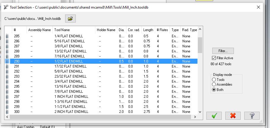
6 You should now see the ½ flat endmill or straight bit in this window. This is the bit we will use to cut the piece. Enter 100 for feed rate And 30 for plunge rate
7
8

.")
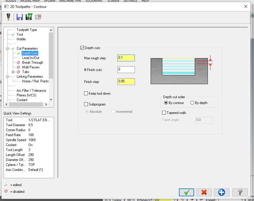
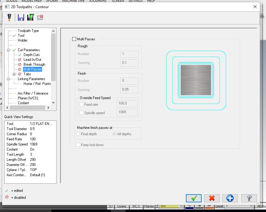
9 Basically, we just set up the parameters for the contour cut. We still need to set the depth of the cut. But, the only Cut Parameters that should be turned on are the depth cuts (set at.125). It should look like the picture on the left.

10 To set the depth of the cut, please enter the below values. In the Linking Parameters tab. Notice that all the values are Absolute and the depth is a Now we can finally hit the OK check to enter all these values and MasterCAM will draw the contour toolpath on the circle.

11 Result: You should see a light blue toolpath inside the inside circle. The blue toolpath represents the center of the tool. If your drawing/toolpath does not look like this, please get assistance. The second toolpath is similar to the first. It will be a contour with the same cut parameters and same tool, but we will not go all the way through the piece. This time we will make a rabbit, so the depth will be -3/8 or

")
12 Go to toolpaths/contour. Again, go to single, and click on the outside circle this time. Click on the outside circle Once the outside circle is selected (it should turn white and have a green arrow on the right side of it) click on the green check box (ok) to finish the selection.
.")
13 After you hit the OK button for selecting geometry for the toolpath, the 2D contour toolpath window pops up. This should have all the same settings we set for the first toolpath except for the depth. So you can check all the cut parameters and see if they are the same (they should be, if not just enter the same information for the last contour). Once you check the cut parameters, go to linking parameters and enter the depth of Then hit OK.

14 Result: You should see a second light blue toolpath inside the second circle. The blue toolpath represents the center of the tool. If your drawing/toolpath does not look like this, please get assistance. Now it s time for the plow for the dial and clock movement. This plow is represented by the small vertical line in the center of the clock front geometry. It is still a contour toolpath, so the procedure is similar. The only difference is the cutter compensation needs to be turned off, so the center of the cutter follows the line. Go to Toolpaths/Countour


15 Click on the single option. Then click on the top portion of the vertical line. Then hit OK This contour tool path properties are similar to the other ones, but we need a couple of changes. So follow along and enter the following information into all the windows.


16 The same tool we used last time should be active. This is correct. In cut parameters, change the compensation type to OFF. This will put the center of the cutter on the line.
17 All the other cut parameters should be off (they should have the little red next to them).


18 Most of the values should be the same as before, please check. Then enter the depth of and hit the green check. This should draw the toolpath, you probably will not see the toolpath since the center of the cutter follows the line. So you probably just see the line unless you are in a different view. Result:
19 If you go to an isometric view you should see the toolpath depth cuts. The light blue lines that stack on top of each other. For the next procedure we want to verify the toolpath, basically we are going to virtually cut the piece on the computer. So we are going to look at the geometry and toolpaths in a 3D view so we can see what is going to happen better. Go to an isometric view if you did not already, zoom in\out, and center the work piece so it looks something like what is below.


20 To verify the toolpaths, do the following: 1 st click this green arrow to select all the toolpaths. Then click this the Verify button. It s like a folder with a green check. The MasterCAM Toolpath Simulator should open up in a new window. Like below.
21 To verify, click the play button at the bottom of the MasterCAM Simulator, and your work piece should look like below. Please show your instructor to receive credit. Congratulations, you drew all the toolpaths you need for the clock front. Please show Mr. Marmor so he can sign off on your completion of the process..
10 x 16 Cutting Board - Juice Groove in MasterCAM
 10 x 16 Cutting Board - Juice Groove in MasterCAM Check to make sure the nethasp is working/turned on to network. Go to ALL APPs/Mastercam x8/nethasp After the computer reads the nethasp, these programs
MasterCAM for Dresser Valet
 MasterCAM for Dresser Valet Check to make sure the nethasp is working/turned on to network. Go to ALL APPs/Mastercam x8/nethasp After the computer reads the nethasp, these programs should show up. If not
Kerf Bent Clock Front Geometry in MasterCAM
 Kerf Bent Clock Front Geometry in MasterCAM Check to make sure the nethasp is working/turned on to network. Go to ALL APPs/Mastercam x8/nethasp After the computer reads the nethasp, these programs should
Kerf Bent Clock Front Geometry in MasterCAM. Open the MasterCAM application, it should look something like below.
 Kerf Bent Clock Front Geometry in MasterCAM Open the MasterCAM application, it should look something like below. First thing is to figure out what you are making.using the measurements from your plans,
MasterCAM for Sculpted Bench
 MasterCAM for Sculpted Bench Check to make sure the nethasp is working/turned on to network. Go to ALL APPs/Mastercam x8/nethasp After the computer reads the nethasp, these programs should show up. If
In this tutorial you will open a Dxf file and create the toolpath that cut the external of the part.
 Tutorial 2 - Open Dxf file and create the outside Contour toolpath. In this tutorial you will open a Dxf file and create the toolpath that cut the external of the part. Caution: CNC machines are potentially
ENGI 7962 Mastercam Lab Mill 1
 ENGI 7962 Mastercam Lab Mill 1 Starting a Mastercam file: Once the SolidWorks models is complete (all sketches are Fully Defined), start up Mastercam and select File, Open, Files of Type, SolidWorks Files,
In this tutorial you will open a Dxf file and create the toolpath to remove the material contained in a closed profile.
 Tutorial 3 - Open Dxf file and create the Pocket toolpath. In this tutorial you will open a Dxf file and create the toolpath to remove the material contained in a closed profile. Caution: CNC machines
for Solidworks TRAINING GUIDE LESSON-9-CAD
 for Solidworks TRAINING GUIDE LESSON-9-CAD Mastercam for SolidWorks Training Guide Objectives You will create the geometry for SolidWorks-Lesson-9 using SolidWorks 3D CAD software. You will be working
Box Tray Geometry in MasterCAM
 Box Tray Geometry in MasterCAM First thing is to figure out what you are making. The best way is to get graph paper and draw out the tray full size or draw the pockets right on your work piece. Then you
Tutorial 4 - Open Dxf file and create multiple toolpaths (Contour, Pocket and Drill).
.") Tutorial 4 - Open Dxf file and create multiple toolpaths (Contour, Pocket and Drill). In this tutorial you will open a Dxf file and create the toolpath that cut the external of the part, another toolpath
Tutorial 4 - Open Dxf file and create multiple toolpaths (Contour, Pocket and Drill). In this tutorial you will open a Dxf file and create the toolpath that cut the external of the part, another toolpath
Flip for User Guide. Inches. When Reliability Matters
 Flip for User Guide Inches by When Reliability Matters Mastercam HSM Performance Pack Tutorial 1 Mastercam HSM Performance Pack Tutorial Tutorial I... 2 Getting started... 2 Tools used... 2 Roughing...
Flip for User Guide. Metric. When Reliability Matters
 Flip for User Guide Metric by When Reliability Matters Mastercam HSM Performance Pack Tutorial 1 Mastercam HSM Performance Pack Tutorial Tutorial I... 2 Getting started... 2 Tools used... 2 Roughing...
Figure 1: NC Lathe menu
 Click To See: How to Use Online Documents SURFCAM Online Documents 685)&$0Ã5HIHUHQFHÃ0DQXDO 5 /$7+( 5.1 INTRODUCTION The lathe mode is used to perform operations on 2D geometry, turned on two axis lathes.
Module 1E: Parallel-Line Flat Pattern Development of Sheet- Metal Folded Model Wrapping the 3D Space of An Oblique Circular Cylinder
 Inventor (10) Module 1E: 1E- 1 Module 1E: Parallel-Line Flat Pattern Development of Sheet- Metal Folded Model Wrapping the 3D Space of An Oblique Circular Cylinder In this Module, we will explore the topic
MadCAM 2.0: Drill Pattern Toolpath
 MadCAM 2.0: Drill Pattern Toolpath Digital Media Tutorial 2005-2006 MadCAM 2.0 can create a toolpath to drill holes directly into your material. The bit plunges in and out of the material without moving
AC : IMPLEMENTATION OF CAD/CAM/CNC CURRICULUM USING MASTERCAM X SOFTWARE IN TECHNICAL PROGRAMS
 AC 2008-297: IMPLEMENTATION OF CAD/CAM/CNC CURRICULUM USING MASTERCAM X SOFTWARE IN TECHNICAL PROGRAMS Farzin Heidari, Texas A&M University, Kingsville American Society for Engineering Education, 2008
TERMS OF USE. Mastercam X6 What s New
 What s New Mastercam X6 What s New Date: October 2011 Copyright 2011 CNC Software, Inc. All rights reserved. First Printing: October 2011 Software: Mastercam X6 TERMS OF USE Use of this document is subject
Figure 1: NC EDM menu
 Click To See: How to Use Online Documents SURFCAM Online Documents 685)&$0Ã5HIHUHQFHÃ0DQXDO 6 :,5(('0 6.1 INTRODUCTION SURFCAM s Wire EDM mode is used to produce toolpaths for 2 Axis and 4 Axis EDM machines.
Module 1G: Creating a Circle-Based Cylindrical Sheet-metal Lateral Piece with an Overlaying Lateral Edge Seam And Dove-Tail Seams on the Top Edge
 Inventor (10) Module 1G: 1G- 1 Module 1G: Creating a Circle-Based Cylindrical Sheet-metal Lateral Piece with an Overlaying Lateral Edge Seam And Dove-Tail Seams on the Top Edge In Module 1A, we have explored
Module 1C: Adding Dovetail Seams to Curved Edges on A Flat Sheet-Metal Piece
 1 Module 1C: Adding Dovetail Seams to Curved Edges on A Flat Sheet-Metal Piece In this Module, we will explore the method of adding dovetail seams to curved edges such as the circumferential edge of a
Tutorial 1 getting started with the CNCSimulator Pro
 CNCSimulator Blog Tutorial 1 getting started with the CNCSimulator Pro Made for Version 1.0.6.5 or later. The purpose of this tutorial is to learn the basic concepts of how to use the CNCSimulator Pro
Getting Started. Right click on Lateral Workplane. Left Click on New Sketch
 Getting Started 1. Open up PTC Pro/Desktop by either double clicking the icon or through the Start button and in Programs. 2. Once Pro/Desktop is open select File > New > Design 3. Close the Pallet window
AUTODESK INVENTOR Trial Projects
 AUTODESK INVENTOR Trial Projects Drawing Creation Create detailed drawings of a collar flange PART 1: CREATING DRAWING VIEWS page: 2 1. 2. 3. Start by clicking the Projects icon in the ribbon. Navigate
How to Build a Game Console. David Hunt, PE
 How to Build a Game Console David Hunt, PE davidhunt@outdrs.net Covering: Drafts Fillets Shells Patterns o Linear o Circular Using made-for-the-purpose sketches to define reference geometry Using reference
Purdue AFL. CATIA CAM Process Reference Rev. B
 Purdue AFL CATIA CAM Process Reference Rev. B Revision Notes Revision - of this document refers to the CATIA v5r21 deployment of the AFL CATIA Environment. All information contained in this reference document
Module 1H: Creating an Ellipse-Based Cylindrical Sheet-metal Lateral Piece
 Inventor (10) Module 1H: 1H- 1 Module 1H: Creating an Ellipse-Based Cylindrical Sheet-metal Lateral Piece In this Module, we will learn how to create an ellipse-based cylindrical sheetmetal lateral piece
Module 2: Radial-Line Sheet-Metal 3D Modeling and 2D Pattern Development: Right Cone (Regular, Frustum, and Truncated)
") Inventor (5) Module 2: 2-1 Module 2: Radial-Line Sheet-Metal 3D Modeling and 2D Pattern Development: Right Cone (Regular, Frustum, and Truncated) In this tutorial, we will learn how to build a 3D model
Inventor (5) Module 2: 2-1 Module 2: Radial-Line Sheet-Metal 3D Modeling and 2D Pattern Development: Right Cone (Regular, Frustum, and Truncated) In this tutorial, we will learn how to build a 3D model
Table of Contents. Lesson 1 Getting Started
 NX Lesson 1 Getting Started Pre-reqs/Technical Skills Basic computer use Expectations Read lesson material Implement steps in software while reading through lesson material Complete quiz on Blackboard
1. Create a 2D sketch 2. Create geometry in a sketch 3. Use constraints to position geometry 4. Use dimensions to set the size of geometry
 2.1: Sketching Many features that you create in Fusion 360 start with a 2D sketch. In order to create intelligent and predictable designs, a good understanding of how to create sketches and how to apply
Fusion 360 Part Setup. Tutorial
 Fusion 360 Part Setup Tutorial Table of Contents MODEL SETUP CAM SETUP TOOL PATHS MODEL SETUP The purpose of this tutorial is to demonstrate start to finish, importing a machineable part to generating
AEROPLANE. Create a New Folder in your chosen location called Aeroplane. The four parts that make up the project will be saved here.
 AEROPLANE Prerequisite Knowledge Previous knowledge of the following commands is required to complete this lesson. Sketching (Line, Rectangle, Arc, Add Relations, Dimensioning), Extrude, Assemblies and
Using Surfcam to Produce a Numeric Control (NC) Program Part #1 Surfcam Demonstration Version Use
 Program Part #1 Surfcam Demonstration Version Use") Using Surfcam to Produce a Numeric Control (NC) Program Part #1 Surfcam Demonstration Version Use An Introduction to the CAD/CAM Process Instructions for 3 Axis Programming Using the D&M CNC Milling Machine
Using Surfcam to Produce a Numeric Control (NC) Program Part #1 Surfcam Demonstration Version Use An Introduction to the CAD/CAM Process Instructions for 3 Axis Programming Using the D&M CNC Milling Machine
CHAPTER 15. Cross Section Sheets. None, except batch processing of an input file.
 CHAPTER 15 Cross Section Sheets 15.1 Introduction Objectives Project Manager Menu Bar Application Learn the procedures for laying out cross section sheets. Cross Section Sheets None, except batch processing
How to draw the CB South Kerf Bent Clock:
 How to draw the CB South Kerf Bent Clock: Open sketch up, use the Product Design and Woodworking template with Inches as the units. If there is a person in the drawing space, you can delete him/her. When
Quick Start for Autodesk Inventor
 Quick Start for Autodesk Inventor Autodesk Inventor Professional is a 3D mechanical design tool with powerful solid modeling capabilities and an intuitive interface. In this lesson, you use a typical workflow
Sheet Metal OverviewChapter1:
 Sheet Metal OverviewChapter1: Chapter 1 This chapter describes the terminology, design methods, and fundamental tools used in the design of sheet metal parts. Building upon these foundational elements
Sheet Metal Punch ifeatures
 Lesson 5 Sheet Metal Punch ifeatures Overview This lesson describes punch ifeatures and their use in sheet metal parts. You use punch ifeatures to simplify the creation of common and specialty cut and
Prasanth. Lathe Machining
 Lathe Machining Overview Conventions What's New? Getting Started Open the Part to Machine Create a Rough Turning Operation Replay the Toolpath Create a Groove Turning Operation Create Profile Finish Turning
Processing Gerber Files in CircuitPro
 Processing Gerber Files in CircuitPro Requirements 1. Circuit Pro version 1.5 revision 164 or higher 2. Set of Gerber Files Process Steps 1. Execute Process Planning Wizard. a. Press the process planning
8 Working Drawings in AutoCAD
 8 Working Drawings in AutoCAD Most engineering designs consist of more than a single part. Usually there are a several or many parts that must fit and work together. When we are creating the drawings of
What s new in IGEMS R9
 General changes and CAD-commands What s new in IGEMS R9 Page 1 General changes and CAD-commands What s new in IGEMS R9 This document is not a complete manual. It describes only the differences between
AutoCAD Civil 3D 2009 ESSENTIALS
 AutoCAD Civil 3D 2009 ESSENTIALS SDC PUBLICATIONS Schroff Development Corporation www.schroff.com Better Textbooks. Lower Prices. Alignments and Profiles Section 2: Profiles In this section you learn how
Deck Tutorial. Decks and Porches. Drawing Decks
 Deck Tutorial The Deck Tutorial continues where the Landscaping Tutorial left off, and explains how to create a deck off the back of the house and connect it to the terrain with an exterior staircase.
Introduction to Parametric Modeling AEROPLANE. Design & Communication Graphics 1
 AEROPLANE Design & Communication Graphics 1 Object Analysis sheet Design & Communication Graphics 2 Aeroplane Assembly The part files for this assembly are saved in the folder titled Aeroplane. Open an
Certified SOLIDWORKS Professional Advanced Preparation Materials
 Includes Preparation for Five Advanced Certification Exams Certified SOLIDWORKS Professional Advanced Preparation Materials Sheet Metal, Weldments, Surfacing, Mold Tools and Drawing Tools SOLIDWORKS 2016
User Guide V10 SP1 Addendum
 Alibre Design User Guide V10 SP1 Addendum Copyrights Information in this document is subject to change without notice. The software described in this document is furnished under a license agreement or
CNC Machinery. Module 5: CNC Programming / Milling. IAT Curriculum Unit PREPARED BY. August 2009
 CNC Machinery Module 5: CNC Programming / Milling PREPARED BY IAT Curriculum Unit August 2009 Institute of Applied Technology, 2009 ATM313-CNC Module 5: CNC Programming / Milling Module Objectives: 1.
Creo: Hole, Fillet, and Round Layout/Dimension Tutorial. By: Matthew Jourden Brighton High School
 Creo: Hole, Fillet, and Round Layout/Dimension Tutorial Layout of a Part with Holes 1. Open a blank drawing with your border and title block By: Matthew Jourden Brighton High School 2. Place the front,
Machinist--Cert Students apply industry standard safety practices and specific safety requirements for different machining operations.
 MTT Date: 09/13/2018 TECHNOLOGY MTT Machine Tool Technology--AA Students apply industry standard safety practices and specific safety requirements for different machining operations. Students calculate
Anchor Block Draft Tutorial
 Anchor Block Draft Tutorial In the following tutorial you will create a drawing of the anchor block shown. The tutorial covers such topics as creating: Orthographic views Section views Auxiliary views
Name: Date Completed: Basic Inventor Skills I
 Name: Date Completed: Basic Inventor Skills I 1. Sketch, dimension and extrude a basic shape i. Select New tab from toolbar. ii. Select Standard.ipt from dialogue box by double clicking on the icon. iii.
AutoCAD Tutorial First Level. 2D Fundamentals. Randy H. Shih SDC. Better Textbooks. Lower Prices.
 AutoCAD 2018 Tutorial First Level 2D Fundamentals Randy H. Shih SDC PUBLICATIONS Better Textbooks. Lower Prices. www.sdcpublications.com Powered by TCPDF (www.tcpdf.org) Visit the following websites to
Engineering & Computer Graphics Workbook Using SolidWorks 2014
 Engineering & Computer Graphics Workbook Using SolidWorks 2014 Ronald E. Barr Thomas J. Krueger Davor Juricic SDC PUBLICATIONS Better Textbooks. Lower Prices. www.sdcpublications.com Powered by TCPDF (www.tcpdf.org)
Conversational Programming. Alexsys Operator Manual
 Conversational Programming Alexsys Operator Manual Alexsys Operator Manual 1. Overview ALEXSYS is a programming system for CNC machining centers. That combines features of CAD / CAM systems with typical
VisualCAM 2018 TURN Quick Start MecSoft Corporation
 2 Table of Contents About this Guide 4 1 About... the TURN Module 4 2 Using this... Guide 4 3 Useful... Tips 5 Getting Ready 7 1 Running... VisualCAM 2018 7 2 About... the VisualCAD Display 7 3 Launch...
Getting Started. Terminology. CNC 1 Training
 CNC 1 Training Getting Started What You Need for This Training Program This manual 6 x 4 x 3 HDPE 8 3/8, two flute, bottom cutting end mill, 1 Length of Cut (LOC). #3 Center Drill 1/4 drill bit and drill
Engineering & Computer Graphics Workbook Using SOLIDWORKS
 Engineering & Computer Graphics Workbook Using SOLIDWORKS 2017 Ronald E. Barr Thomas J. Krueger Davor Juricic SDC PUBLICATIONS Better Textbooks. Lower Prices. www.sdcpublications.com Powered by TCPDF (www.tcpdf.org)
Design & Manufacturing II. The CAD/CAM Labs. Lab I Process Planning G-Code Mastercam Lathe
 2.008 Design & Manufacturing II The CAD/CAM Labs Lab I Process Planning G-Code Mastercam Lathe Lab II Mastercam Mill Check G-Code Lab III CNC Mill & Lathe Machining OBJECTIVE BACKGROUND LAB EXERCISES DELIVERABLES
Introduction to CATIA V5
 Introduction to CATIA V5 Release 17 (A Hands-On Tutorial Approach) Kirstie Plantenberg University of Detroit Mercy SDC PUBLICATIONS Schroff Development Corporation www.schroff.com Better Textbooks. Lower
AutoCAD 2020 Fundamentals
 Autodesk AutoCAD 2020 Fundamentals ELISE MOSS Autodesk Certified Instructor SDC PUBLICATIONS Better Textbooks. Lower Prices. www.sdcpublications.com Powered by TCPDF (www.tcpdf.org) Visit the following
How to Create Website Banners
 How to Create Website Banners In the following instructions you will be creating banners in Adobe Photoshop Elements 6.0, using different images and fonts. The instructions will consist of finding images,
AutoCAD LT 2012 Tutorial. Randy H. Shih Oregon Institute of Technology SDC PUBLICATIONS. Schroff Development Corporation
 AutoCAD LT 2012 Tutorial Randy H. Shih Oregon Institute of Technology SDC PUBLICATIONS www.sdcpublications.com Schroff Development Corporation AutoCAD LT 2012 Tutorial 1-1 Lesson 1 Geometric Construction
Chapter 2. Modifying, Extruding and Revolving the Sketches. Learning Objectives. Commands Covered AMMODDIM AMEXTRUDE AMREVOLVE
 Chapter 2 Modifying, Extruding and Revolving the Sketches Learning Objectives After completing this chapter, you will be able to: Modify the desired sketch using the AMMODDIM command. Extrude the desired
Apple Photos Quick Start Guide
 Apple Photos Quick Start Guide Photos is Apple s replacement for iphoto. It is a photograph organizational tool that allows users to view and make basic changes to photos, create slideshows, albums, photo
Toothbrush Holder Project 2D Machining
 Toothbrush Holder Project 2D Machining Prerequisite Toothbrush Holder drawn and saved as a DXF file in SolidWorks Focus of the Lesson On completion of this exercise you will have: Used the Techsoft 2D
DIRECTIONS FOR CREATING A WORDPRESS BLOG FOR SCIENCE WRITING ONLINE
 DIRECTIONS FOR CREATING A WORDPRESS BLOG FOR SCIENCE WRITING ONLINE Create a science blog on www.wordpress.com AND read other people s science blogs. 1. Open up your internet browser (preferably Google
Principles and Applications of Microfluidic Devices AutoCAD Design Lab - COMSOL import ready
 Principles and Applications of Microfluidic Devices AutoCAD Design Lab - COMSOL import ready Part I. Introduction AutoCAD is a computer drawing package that can allow you to define physical structures
Quilt Pro 6 Lesson Quilt in a Quilt
 Quilt Pro 6 Lesson Quilt in a Quilt Quilt in a Quilt The Inner Quilt This quilt is a very complex design. We will cover a unique technique not covered in the manual. While any one can master the techniques
UNIT 11: Revolved and Extruded Shapes
 UNIT 11: Revolved and Extruded Shapes In addition to basic geometric shapes and importing of three-dimensional STL files, SOLIDCast allows you to create three-dimensional shapes that are formed by revolving
Alternatively, the solid section can be made with open line sketch and adding thickness by Thicken Sketch.
 Sketcher All feature creation begins with two-dimensional drawing in the sketcher and then adding the third dimension in some way. The sketcher has many menus to help create various types of sketches.
SCRAPENDIPITY Designs. Electric Quilt 7 Tutorial. Building a Quilt
 Electric Quilt 7 Tutorial Building a Quilt When you start Electric Quilt up, you will see this screen. Type the name of your quilt and hit OK Now we need to make sure we have the correct layout. Go to
Using Siemens NX 11 Software. The connecting rod
 Using Siemens NX 11 Software The connecting rod Based on a Catia tutorial written by Loïc Stefanski. At the end of this manual, you should obtain the following part: 1 Introduction. Start NX 11 and open
Toothbrush Holder. A drawing of the sheet metal part will also be created.
 Prerequisite Knowledge Previous knowledge of the following commands is required to complete this lesson; Sketch (Line, Centerline, Circle, Add Relations, Smart Dimension,), Extrude Boss/Base, and Edit
1. Creating geometry based on sketches 2. Using sketch lines as reference 3. Using sketches to drive changes in geometry
 4.1: Modeling 3D Modeling is a key process of getting your ideas from a concept to a read- for- manufacture state, making it core foundation of the product development process. In Fusion 360, there are
CC3 and Perspectives A Campaign Cartographer 3/3+ Tutorial. Part 1 - Basics
 CC3 and Perspectives A Campaign Cartographer 3/3+ Tutorial by Joachim de Ravenbel Part 1 - Basics Conventions Throughout this tutorial, I will use a color coding to clearly identify all the keywords: Sheet
EASY CNC. Table of Contents
 Square 1 Electronics announces its new book by David Benson, "Easy CNC", A Beginner's Guide to CNC" The complete table of contents follows: This book was written by David Benson (8-1/2 x 11", 200 pages,
Landscaping Tutorial
 Landscaping Tutorial This tutorial describes how to use Home Designer Architectural s Terrain Tools. In it, you will learn how to add elevation information to your terrain, how to create terrain features,
Photo Story Tutorial
 Photo Story Tutorial To create a new Photo Story Project: 1. Start 2. Programs 3. Photo Story 4. Begin a New Story 5. Next 6. Import Pictures 7. Click on your Flash Drive s name from the window on the
Landscaping Tutorial. Chapter 5:
 Chapter 5: Landscaping Tutorial This tutorial was written to help you learn how to use Home Designer Landscape and Deck s Terrain tools. In this tutorial, you will learn how to add elevation information
Relative Coordinates
 AutoCAD Essentials Most drawings are created using relative coordinates. This means that the next point is set from the last point drawn. The last point drawn is stored as temporary 0,0". AutoCAD uses
Working With Drawing Views-I
 Chapter 12 Working With Drawing Views-I Learning Objectives After completing this chapter you will be able to: Generate standard three views. Generate Named Views. Generate Relative Views. Generate Predefined
Introduction to Sheet Metal Features SolidWorks 2009
 SolidWorks 2009 Table of Contents Introduction to Sheet Metal Features Base Flange Method Magazine File.. 3 Envelopment & Development of Surfaces.. 14 Development of Transition Pieces.. 23 Conversion to
Unit. Drawing Accurately OVERVIEW OBJECTIVES INTRODUCTION 8-1
 8-1 Unit 8 Drawing Accurately OVERVIEW When you attempt to pick points on the screen, you may have difficulty locating an exact position without some type of help. Typing the point coordinates is one method.
< Then click on this icon on the vertical tool bar that pops up on the left side.
 Pipe Cavity Tutorial Introduction The CADMAX Solid Master Tutorial is a great way to learn about the benefits of feature-based parametric solid modeling with CADMAX. We have assembled several typical parts
Section Table of Contents: Section 16.0
 Section 16.0 Table of Contents: Section 16.0 Overview - Section 16.0... 16.0-3 Plotting Single Sheets... 16.0-3 Publishing... 16.0-5 Creating DWFs or PDFs (with Sheet Sets)... 16.0-6 Overview - Section
When you complete this assignment you will:
 Objjectiives When you complete this assignment you will: 1. sketch and dimension circles and arcs. 2. cut holes in the model using the cut feature of the extrusion command. 3. create Arcs using the trim
AASHTOWare Bridge Rating Training. T6 Truss Cross Sections and Graphics (BrR 6.4)
") AASHTOWare Bridge Rating Training T6 Truss Cross Sections and Graphics (BrR 6.4) This example describes how to define a Channelbox truss cross section with stacking plates on either side of channel webs
AASHTOWare Bridge Rating Training T6 Truss Cross Sections and Graphics (BrR 6.4) This example describes how to define a Channelbox truss cross section with stacking plates on either side of channel webs
Constructing a Wedge Die
 1-(800) 877-2745 www.ashlar-vellum.com Using Graphite TM Copyright 2008 Ashlar Incorporated. All rights reserved. C6CAWD0809. Ashlar-Vellum Graphite This exercise introduces the third dimension. Discover
SolidWorks Reference Geometry
 SolidWorks Reference Geometry IDeATe Laser Micro Part 2 Dave Touretzky and Susan Finger 1. Symmetry and Reference Geometry Today, you ll make this part bear-like face and then cut it on the laser cutter:
Assignment 5 CAD Mechanical Part 1
 Assignment 5 CAD Mechanical Part 1 Objectives In this assignment you will apply polyline, offset, copy, move, and rotated dimension commands, as well as skills learned in earlier assignments. Getting Started
with MultiMedia CD Randy H. Shih Jack Zecher SDC PUBLICATIONS Schroff Development Corporation
 with MultiMedia CD Randy H. Shih Jack Zecher SDC PUBLICATIONS Schroff Development Corporation WWW.SCHROFF.COM Lesson 1 Geometric Construction Basics AutoCAD LT 2002 Tutorial 1-1 1-2 AutoCAD LT 2002 Tutorial
Alibre Design Tutorial: Loft, Extrude, & Revolve Cut Loft-Tube-1
 Alibre Design Tutorial: Loft, Extrude, & Revolve Cut Loft-Tube-1 Part Tutorial Exercise 5: Loft-Tube-1 [Complete] In this Exercise, We will set System Parameters first, then part options. Then, in sketch
Create all plan and profile sheets in the current drawing. Create all plan and profile sheets in individual drawings.
 NOTES Module 18 Roadway Plan Production In this module, you learn how to work with Roadway Plan Production tools in AutoCAD Civil 3D. The Plan Production tools are used to automate the generation of plan
PRODIM CT 3.0 MANUAL the complete solution
 PRODIM CT 3.0 MANUAL the complete solution We measure it all! General information Copyright All rights reserved. Apart from the legally laid down exceptions, no part of this publication may be reproduced,
CNC Turning Training CNC MILLING / ROUTING TRAINING GUIDE. Page 1
 CNC Turning Training www.denford.co.uk Page 1 Table of contents Introduction... 3 Start the VR Turning Software... 3 Configure the software for the machine... 4 Load your CNC file... 5 Configure the tooling...
Shaft Hanger - SolidWorks
 ME-430 INTRODUCTION TO COMPUTER AIDED DESIGN Shaft Hanger - SolidWorks BY: DR. HERLI SURJANHATA ASSIGNMENT Submit TWO isometric views of the Shaft Hanger with your report, 1. Shaded view of the trimetric
Deck Tutorial. Decks and Porches. Drawing Decks
 Deck Tutorial The Deck Tutorial continues where the Landscaping Tutorial left off, and explains how to create a deck off the back of the house and connect it to the terrain with an exterior staircase.
Autodesk AutoCAD Architecture 2015 Fundamentals
 Autodesk AutoCAD Architecture 2015 Fundamentals Elise Moss SDC P U B L I C AT I O N S Authorized Author Better Textbooks. Lower Prices. www.sdcpublications.com Powered by TCPDF (www.tcpdf.org) Visit the
Digital Media Tutorial Written By John Eberhart
 MadCAM MadCAM 5.0: Large 4.1: Large & Medium CNC Tool CNC Path Tool Path Generator Generator Digital Media Tutorial Written By John Eberhart MadCAM is a tool path generator that works inside Rhino. It