10 x 16 Cutting Board - Juice Groove in MasterCAM
|
|
|
- Denis Hardy
- 6 years ago
- Views:
Transcription


1 10 x 16 Cutting Board - Juice Groove in MasterCAM Check to make sure the nethasp is working/turned on to network. Go to ALL APPs/Mastercam x8/nethasp

2 After the computer reads the nethasp, these programs should show up. If not ask your instructor. After you check that, please open the MasterCAM application, it should look something like below.

 To start a project, we need to set our specific CNC router and set up the stock sizes.")
3 First thing is to figure out what you are making.using the measurements from your plans, you will draw your geometry (geometry is a generic term for lines, arcs, etc. in a computer drawing program). This geometry must be drawn in the 1 st quadrant of the coordinate system, so positive x and y. The placement of the geometry matters since we will later be cutting out the part using the CNC Router. The CNC Router uses the coordinates from where you draw the geometry. F9 will display the x/y axis such as: Draw starting at the origin (0,0) To start a project, we need to set our specific CNC router and set up the stock sizes. MasterCAM can write NC code for different manufacturers of CNC equipment. Our router is called a Forest Scientific Velocity 3 axis mill. MasterCAM will write the correct type of code as long as we pick the correct machine definition. Currently the only computer with this machine definition is the one hooked to the CNC router, so please just pick the default, then your instructor will change it at the CNC machine. This is a critical first step, without a machine definition, the CNC router will crash.litterly the tool bit will dive into the table top. Goto Machine Type/Mill/Default.


4 The result: there should be one machine group ( Machine Group -1 ) that says Properties Mill Default, if there is other Machine Groups, right-click and delete them. Stock Setup The Toolpath Operations Manager is the tool palette that is docked on the left of the screen. It is titled Toolpaths. This displays all the specific information about the tool paths (what the CNC router will cut). Expand the properties tab in the Toolpath manager. Then click on stock setup.
 Leave these x,y,z s at 0 After you click ok in the stock setup, you should see a red dashed red rectangle that represents your stock.")
5 Setup the stock: Enter the measurements 16 for y 10 for x 1.25 for z Set the stock origin by clicking on this corner. Check Display Click the Green Check Mark (OK) Leave these x,y,z s at 0 After you click ok in the stock setup, you should see a red dashed red rectangle that represents your stock. Zoom in or out so that you see the whole piece. Zoom with the scroll wheel on the mouse, and use the arrow keys to move left/right/up/down.
6 Entering Geometry It s time to start drawing some geometry. If you draw what you want on your work piece it helps figure out the (x,y) coordinates. For this operation, the tool bit will follow a rectangle. The rectangle should be 1 smaller all the way around compared to your work piece. The cutting board should be 10 x 16, so the rectangle will be 8 x 14, with a 1 margin all the way around. It starts at (1,1) and the other corner is (15,9). We need the rectangle tool, and we can enter those values for the two corners of the rectangle. First, click on the rectangle tool Second, MasterCAM prompts you for the the first corner (x,y) values. You can just start typing the x and y values. When you start entering a value, MCAM will open the window where the values appear. After you enter the first coordinate (1,1) you can hit enter, and MCAM will anchor the first corner of the rectangle.
7 Result: MCAM anchored the first corner. It prompts for the second corner. Type (15,9) and hit enter.
8 Result: MCAM anchored the second corner. It sketches the geometry first to see if it is correct. Hit enter a second time to draw the rectangle. Once the rectangle is dark blue and correct. You can hit escape to get out of the rectangle tool.
.")

9 Toolpaths: For 2D geometry such as we have, there are 2 main types of tool paths. The first one is a contour. In a contour toolpath, the tool bit will follow a path. The path can be one piece of geometry or multiple pieces of geometry linked together end to end (this is called a chain). When the geometry is selected, you must either pick the single option or the chaining option (multiple objects laid out end to end) before you select the geometry. We are going to complete three contour toolpaths on the three singular pieces of geometry. The second type of toolpath is a pocket. A pocket toolpath will make a cavity inside the selected geometry. An example of a pocket toolpath would be the handles on the bottom of the cutting board. To start the toolpaths, go to Toolpaths/contour When the new NC dialog box comes up, type in a good file name such as Clock Front. Click the green check.
.")
10 The Chaining dialog box should appear. MasterCAM prompts you to select the geometry you want to associate with the toolpath. Click on the bottom line, to select it the chain (the rectangle geometry). Once the rectangle is selected (it should turn white/dashed and have a green arrow on it) click on the green check box (ok) to finish the selection.


11 In the 2D Toolpaths Contour dialog box, please enter the following information: Right- click in this white space


12 You can change the filter to Ball Endmills if you can t find the ¾ ball endmill.


13 You should now see the 3/4 ball endmill in this window. This is the bit we will use to cut the piece. Enter 75 for feed rate And 25 for plunge rate and retract rate
14
15

.")
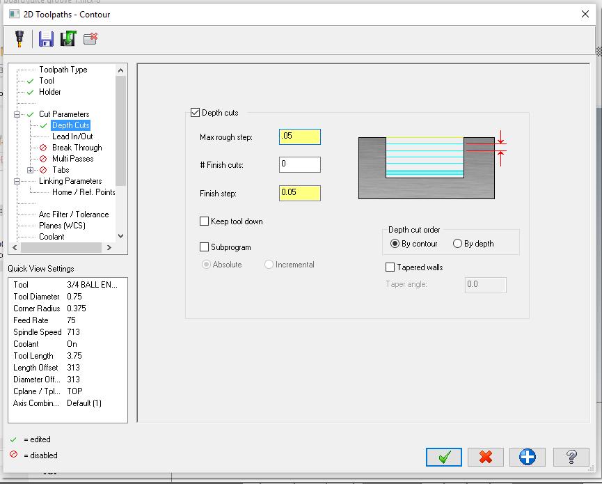
16 Basically, we just set up the parameters for the contour cut. We still need to set the depth of the cut. But, the only Cut Parameters that should be turned on are the depth cuts (set at.05). It should look like the picture on the left.

17 To set the depth of the cut, please enter the below values. In the Linking Parameters tab. Notice that all the values are Absolute and the depth is a -.25 Now we can finally hit the OK check to enter all these values and MasterCAM will draw the contour toolpath on the circle. After you hit the green check, go to an isometric view, to see the toolpath.
18 Result: You should see the blue depth cuts under the dark blue rectangle.

19 If it looks good, save your work. You have completed the Cutting board juice groove.
Box Tray Geometry in MasterCAM
 Box Tray Geometry in MasterCAM First thing is to figure out what you are making. The best way is to get graph paper and draw out the tray full size or draw the pockets right on your work piece. Then you
Kerf Bent Clock Front Geometry in MasterCAM
 Kerf Bent Clock Front Geometry in MasterCAM Check to make sure the nethasp is working/turned on to network. Go to ALL APPs/Mastercam x8/nethasp After the computer reads the nethasp, these programs should
MasterCAM for Dresser Valet
 MasterCAM for Dresser Valet Check to make sure the nethasp is working/turned on to network. Go to ALL APPs/Mastercam x8/nethasp After the computer reads the nethasp, these programs should show up. If not
MasterCAM for Sculpted Bench
 MasterCAM for Sculpted Bench Check to make sure the nethasp is working/turned on to network. Go to ALL APPs/Mastercam x8/nethasp After the computer reads the nethasp, these programs should show up. If
Kerf Bent Clock Front Geometry in MasterCAM. Open the MasterCAM application, it should look something like below.
 Kerf Bent Clock Front Geometry in MasterCAM Open the MasterCAM application, it should look something like below. First thing is to figure out what you are making.using the measurements from your plans,
Kerf Bent Clock Front Toolpaths in MasterCAM. Open the MasterCAM application and open your clock front geometry file.
 Kerf Bent Clock Front Toolpaths in MasterCAM Open the MasterCAM application and open your clock front geometry file. For 2D geometry such as we have, there are 2 main types of tool paths. The first one
for Solidworks TRAINING GUIDE LESSON-9-CAD
 for Solidworks TRAINING GUIDE LESSON-9-CAD Mastercam for SolidWorks Training Guide Objectives You will create the geometry for SolidWorks-Lesson-9 using SolidWorks 3D CAD software. You will be working
ENGI 7962 Mastercam Lab Mill 1
 ENGI 7962 Mastercam Lab Mill 1 Starting a Mastercam file: Once the SolidWorks models is complete (all sketches are Fully Defined), start up Mastercam and select File, Open, Files of Type, SolidWorks Files,
Flip for User Guide. Inches. When Reliability Matters
 Flip for User Guide Inches by When Reliability Matters Mastercam HSM Performance Pack Tutorial 1 Mastercam HSM Performance Pack Tutorial Tutorial I... 2 Getting started... 2 Tools used... 2 Roughing...
Flip for User Guide. Metric. When Reliability Matters
 Flip for User Guide Metric by When Reliability Matters Mastercam HSM Performance Pack Tutorial 1 Mastercam HSM Performance Pack Tutorial Tutorial I... 2 Getting started... 2 Tools used... 2 Roughing...
Using Surfcam to Produce a Numeric Control (NC) Program Part #1 Surfcam Demonstration Version Use
 Program Part #1 Surfcam Demonstration Version Use") Using Surfcam to Produce a Numeric Control (NC) Program Part #1 Surfcam Demonstration Version Use An Introduction to the CAD/CAM Process Instructions for 3 Axis Programming Using the D&M CNC Milling Machine
Using Surfcam to Produce a Numeric Control (NC) Program Part #1 Surfcam Demonstration Version Use An Introduction to the CAD/CAM Process Instructions for 3 Axis Programming Using the D&M CNC Milling Machine
CAMWorks How To Create CNC G-Code for CO2 Dragsters
 Objective: In this chapter we will show how to mill out the axle holes for this CO2 Dragster from the left side. VI.1. Open the previously created file: Dragster axle hole 001.sldprt. VI.2. Select the
Tutorial 4 - Open Dxf file and create multiple toolpaths (Contour, Pocket and Drill).
.") Tutorial 4 - Open Dxf file and create multiple toolpaths (Contour, Pocket and Drill). In this tutorial you will open a Dxf file and create the toolpath that cut the external of the part, another toolpath
Tutorial 4 - Open Dxf file and create multiple toolpaths (Contour, Pocket and Drill). In this tutorial you will open a Dxf file and create the toolpath that cut the external of the part, another toolpath
In this tutorial you will open a Dxf file and create the toolpath that cut the external of the part.
 Tutorial 2 - Open Dxf file and create the outside Contour toolpath. In this tutorial you will open a Dxf file and create the toolpath that cut the external of the part. Caution: CNC machines are potentially
CNC Router Part 2 Training Tutorial
 CNC Router Part 2 Training Tutorial Prepared by Steve Pilon - Version 1.1 September 2017 A Index B - Intro A- Index B- Intro C- Objective D- Required Items E- Opening CamBam and Loading a DXF F- Preparing
In this tutorial you will open a Dxf file and create the toolpath to remove the material contained in a closed profile.
 Tutorial 3 - Open Dxf file and create the Pocket toolpath. In this tutorial you will open a Dxf file and create the toolpath to remove the material contained in a closed profile. Caution: CNC machines
Figure 1: NC EDM menu
 Click To See: How to Use Online Documents SURFCAM Online Documents 685)&$0Ã5HIHUHQFHÃ0DQXDO 6 :,5(('0 6.1 INTRODUCTION SURFCAM s Wire EDM mode is used to produce toolpaths for 2 Axis and 4 Axis EDM machines.
AutoCAD 2D. Table of Contents. Lesson 1 Getting Started
 AutoCAD 2D Lesson 1 Getting Started Pre-reqs/Technical Skills Basic computer use Expectations Read lesson material Implement steps in software while reading through lesson material Complete quiz on Blackboard
Figure 1: NC Lathe menu
 Click To See: How to Use Online Documents SURFCAM Online Documents 685)&$0Ã5HIHUHQFHÃ0DQXDO 5 /$7+( 5.1 INTRODUCTION The lathe mode is used to perform operations on 2D geometry, turned on two axis lathes.
EASY CNC. Table of Contents
 Square 1 Electronics announces its new book by David Benson, "Easy CNC", A Beginner's Guide to CNC" The complete table of contents follows: This book was written by David Benson (8-1/2 x 11", 200 pages,
Creo Extrude Tutorial 2: Cutting and Adding Material
 Creo Extrude Tutorial 2: Cutting and Adding Material 1. Open Creo Parametric 2. File > Open > extrudeturial (From Creo Extrude Tutorial 1) 3. Cutting Material a. Click Extrude Icon > Select the following
CAMWorks How To Create CNC G-Code for CO2 Dragsters
 Creating the Left Side Smooth Finish Tool Path. This chapter will focus on the steps for creating the left side smooth finish tool path. The objective of this chapter is to create to an accurate and highly
CAMWorks How To Create CNC G-Code for CO2 Dragsters. III.1. Save the rough tool path for the bottom of the CO2 Dragster as Dragster bottom 001 rough.
 In this chapter we will create the smooth G-Code tool path for the bottom of our CO2 Dragster. The smooth tool path is necessary to create a finish that requires minimal work to for the designer to later
DEPARTMENT OF MECHANICAL AND INDUSTRIAL ENGINEERING NORTHEASTERN UNIVERSITY
 DEPARTMENT OF MECHANICAL AND INDUSTRIAL ENGINEERING NORTHEASTERN UNIVERSITY CAPSULE PROGRAM Funded by NSF grant #0833636 Tutorial 02 3D Part Modeling SolidWorks 2010 Copyright 2010 Prof. Zeid 3D Part Modeling
Conversational Programming. Alexsys Operator Manual
 Conversational Programming Alexsys Operator Manual Alexsys Operator Manual 1. Overview ALEXSYS is a programming system for CNC machining centers. That combines features of CAD / CAM systems with typical
1. Create a 2D sketch 2. Create geometry in a sketch 3. Use constraints to position geometry 4. Use dimensions to set the size of geometry
 2.1: Sketching Many features that you create in Fusion 360 start with a 2D sketch. In order to create intelligent and predictable designs, a good understanding of how to create sketches and how to apply
CNC: The Machine. Sullivan Fabrication Studio Version 5.1 (beta)
") CNC: The Machine Sullivan Fabrication Studio Version 5.1 (beta) TABLE OF CONTENTS Initial Setup... About the Knowledge Base........... Techno CNC Router... Mounting Material... Install Router Bit... Set
CNC: The Machine Sullivan Fabrication Studio Version 5.1 (beta) TABLE OF CONTENTS Initial Setup... About the Knowledge Base........... Techno CNC Router... Mounting Material... Install Router Bit... Set
Prasanth. Lathe Machining
 Lathe Machining Overview Conventions What's New? Getting Started Open the Part to Machine Create a Rough Turning Operation Replay the Toolpath Create a Groove Turning Operation Create Profile Finish Turning
Fusion 360 Part Setup. Tutorial
 Fusion 360 Part Setup Tutorial Table of Contents MODEL SETUP CAM SETUP TOOL PATHS MODEL SETUP The purpose of this tutorial is to demonstrate start to finish, importing a machineable part to generating
Chapter 2. Modifying, Extruding and Revolving the Sketches. Learning Objectives. Commands Covered AMMODDIM AMEXTRUDE AMREVOLVE
 Chapter 2 Modifying, Extruding and Revolving the Sketches Learning Objectives After completing this chapter, you will be able to: Modify the desired sketch using the AMMODDIM command. Extrude the desired
CNC INTRO WALKTHROUGH GSAPP FABRICATION LAB, FALL 2017
 CNC INTRO WALKTHROUGH GSAPP FABRICATION LAB, FALL 2017 this is a student guide to the procedure of gaining access to the CNC router digital fabrication equipment in the Fabrication Lab at GSAPP. The guide
Toothbrush Holder Project 2D Machining
 Toothbrush Holder Project 2D Machining Prerequisite Toothbrush Holder drawn and saved as a DXF file in SolidWorks Focus of the Lesson On completion of this exercise you will have: Used the Techsoft 2D
Tutorial 1 getting started with the CNCSimulator Pro
 CNCSimulator Blog Tutorial 1 getting started with the CNCSimulator Pro Made for Version 1.0.6.5 or later. The purpose of this tutorial is to learn the basic concepts of how to use the CNCSimulator Pro
MadCAM 2.0: Drill Pattern Toolpath
 MadCAM 2.0: Drill Pattern Toolpath Digital Media Tutorial 2005-2006 MadCAM 2.0 can create a toolpath to drill holes directly into your material. The bit plunges in and out of the material without moving
SMALL OFFICE TUTORIAL
 SMALL OFFICE TUTORIAL in this lesson you will get a down and dirty overview of the functionality of Revit Architecture. The very basics of creating walls, doors, windows, roofs, annotations and dimensioning.
AEROPLANE. Create a New Folder in your chosen location called Aeroplane. The four parts that make up the project will be saved here.
 AEROPLANE Prerequisite Knowledge Previous knowledge of the following commands is required to complete this lesson. Sketching (Line, Rectangle, Arc, Add Relations, Dimensioning), Extrude, Assemblies and
Evaluation Chapter by CADArtifex
 The premium provider of learning products and solutions www.cadartifex.com EVALUATION CHAPTER 2 Drawing Sketches with SOLIDWORKS In this chapter: Invoking the Part Modeling Environment Invoking the Sketching
Table of Contents. Lesson 1 Getting Started
 NX Lesson 1 Getting Started Pre-reqs/Technical Skills Basic computer use Expectations Read lesson material Implement steps in software while reading through lesson material Complete quiz on Blackboard
Drawing and Assembling
 Youth Explore Trades Skills Description In this activity the six sides of a die will be drawn and then assembled together. The intent is to understand how constraints are used to lock individual parts
Computation & Construction Lab. Stinger CNC 3D Milling Workflow
 Computation & Construction Lab Stinger CNC 3D Milling Workflow 3D Single Sided Milling Guidelines - The following steps will guide the user on how to transfer digital work from a design software to setting
AutoCAD Tutorial First Level. 2D Fundamentals. Randy H. Shih SDC. Better Textbooks. Lower Prices.
 AutoCAD 2018 Tutorial First Level 2D Fundamentals Randy H. Shih SDC PUBLICATIONS Better Textbooks. Lower Prices. www.sdcpublications.com Powered by TCPDF (www.tcpdf.org) Visit the following websites to
AutoCAD 2020 Fundamentals
 Autodesk AutoCAD 2020 Fundamentals ELISE MOSS Autodesk Certified Instructor SDC PUBLICATIONS Better Textbooks. Lower Prices. www.sdcpublications.com Powered by TCPDF (www.tcpdf.org) Visit the following
AutoCAD 2018 Fundamentals
 Autodesk AutoCAD 2018 Fundamentals Elise Moss SDC PUBLICATIONS Better Textbooks. Lower Prices. www.sdcpublications.com Powered by TCPDF (www.tcpdf.org) Visit the following websites to learn more about
Creo Revolve Tutorial
 Creo Revolve Tutorial Setup 1. Open Creo Parametric Note: Refer back to the Creo Extrude Tutorial for references and screen shots of the Creo layout 2. Set Working Directory a. From the Model Tree navigate
FlashChart. Symbols and Chart Settings. Main menu navigation. Data compression and time period of the chart. Chart types.
 FlashChart Symbols and Chart Settings With FlashChart you can display several symbols (for example indices, securities or currency pairs) in an interactive chart. You can also add indicators and draw on
Modeling Basic Mechanical Components #1 Tie-Wrap Clip
 Modeling Basic Mechanical Components #1 Tie-Wrap Clip This tutorial is about modeling simple and basic mechanical components with 3D Mechanical CAD programs, specifically one called Alibre Xpress, a freely
Drawing Layouts Paper space & Model Space
 Drawing Layouts Paper space & Model Space Users of Bricscad will have seen the tabs at the bottom left of the drawings area labelled: Model, Layout1, Layout2 but may not know how to use them or what they
8 Working Drawings in AutoCAD
 8 Working Drawings in AutoCAD Most engineering designs consist of more than a single part. Usually there are a several or many parts that must fit and work together. When we are creating the drawings of
Chapter 2. Drawing Sketches for Solid Models. Learning Objectives
 Chapter 2 Drawing Sketches for Solid Models Learning Objectives After completing this chapter, you will be able to: Start a new template file to draw sketches. Set up the sketching environment. Use various
PRODIM CT 3.0 MANUAL the complete solution
 PRODIM CT 3.0 MANUAL the complete solution We measure it all! General information Copyright All rights reserved. Apart from the legally laid down exceptions, no part of this publication may be reproduced,
Getting Started. Right click on Lateral Workplane. Left Click on New Sketch
 Getting Started 1. Open up PTC Pro/Desktop by either double clicking the icon or through the Start button and in Programs. 2. Once Pro/Desktop is open select File > New > Design 3. Close the Pallet window
What s new in IGEMS R9
 General changes and CAD-commands What s new in IGEMS R9 Page 1 General changes and CAD-commands What s new in IGEMS R9 This document is not a complete manual. It describes only the differences between
Isometric Drawings. Figure A 1
 A Isometric Drawings ISOMETRIC BASICS Isometric drawings are a means of drawing an object in picture form for better clarifying the object s appearance. These types of drawings resemble a picture of an
Tutorial 2: Setting up the Drawing Environment
 Drawing size With AutoCAD all drawings are done to FULL SCALE. The drawing limits will depend on the size of the items being drawn. For example if our drawing is the plan of a floor 23.8m X 15m then we
AC : IMPLEMENTATION OF CAD/CAM/CNC CURRICULUM USING MASTERCAM X SOFTWARE IN TECHNICAL PROGRAMS
 AC 2008-297: IMPLEMENTATION OF CAD/CAM/CNC CURRICULUM USING MASTERCAM X SOFTWARE IN TECHNICAL PROGRAMS Farzin Heidari, Texas A&M University, Kingsville American Society for Engineering Education, 2008
Working With Drawing Views-I
 Chapter 12 Working With Drawing Views-I Learning Objectives After completing this chapter you will be able to: Generate standard three views. Generate Named Views. Generate Relative Views. Generate Predefined
Module 1G: Creating a Circle-Based Cylindrical Sheet-metal Lateral Piece with an Overlaying Lateral Edge Seam And Dove-Tail Seams on the Top Edge
 Inventor (10) Module 1G: 1G- 1 Module 1G: Creating a Circle-Based Cylindrical Sheet-metal Lateral Piece with an Overlaying Lateral Edge Seam And Dove-Tail Seams on the Top Edge In Module 1A, we have explored
Cube in a cube Fusion 360 tutorial
 Cube in a cube Fusion 360 tutorial n Before using these instructions, it is helpful to watch this video screencast of the CAD drawing actually being done in the software. Click to link to the video tutorial.
SolidCAM imachining. imachining Tool paths
 SolidCAM imachining SolidCAM imachining is an intelligent High Speed Machining CAM software, designed to produce fast and safe CNC programs to machine mechanical parts. The word fast here means significantly
Relative Coordinates
 AutoCAD Essentials Most drawings are created using relative coordinates. This means that the next point is set from the last point drawn. The last point drawn is stored as temporary 0,0". AutoCAD uses
Introduction to Autodesk Inventor for F1 in Schools (Australian Version)
") Introduction to Autodesk Inventor for F1 in Schools (Australian Version) F1 in Schools race car In this course you will be introduced to Autodesk Inventor, which is the centerpiece of Autodesk s Digital
Introduction to Autodesk Inventor for F1 in Schools (Australian Version) F1 in Schools race car In this course you will be introduced to Autodesk Inventor, which is the centerpiece of Autodesk s Digital
**IT IS STRONGLY RECOMMENDED THAT YOU WATCH THE HOW-TO VIDEOS (BY PROF. SCHULTE-GRAHAME), POSTED ON THE COURSE WEBSITE, PRIOR TO ATTEMPTING THIS LAB
, POSTED ON THE COURSE WEBSITE, PRIOR TO ATTEMPTING THIS LAB") **IT IS STRONGLY RECOMMENDED THAT YOU WATCH THE HOW-TO VIDEOS (BY PROF. SCHULTE-GRAHAME), POSTED ON THE COURSE WEBSITE, PRIOR TO ATTEMPTING THIS LAB GETTING STARTED Step 1. Login to your COE account with
**IT IS STRONGLY RECOMMENDED THAT YOU WATCH THE HOW-TO VIDEOS (BY PROF. SCHULTE-GRAHAME), POSTED ON THE COURSE WEBSITE, PRIOR TO ATTEMPTING THIS LAB GETTING STARTED Step 1. Login to your COE account with
TeleTrader FlashChart
 TeleTrader FlashChart Symbols and Chart Settings With TeleTrader FlashChart you can display several symbols (for example indices, securities or currency pairs) in an interactive chart. You can also add
Constructing a Wedge Die
 1-(800) 877-2745 www.ashlar-vellum.com Using Graphite TM Copyright 2008 Ashlar Incorporated. All rights reserved. C6CAWD0809. Ashlar-Vellum Graphite This exercise introduces the third dimension. Discover
Principles and Applications of Microfluidic Devices AutoCAD Design Lab - COMSOL import ready
 Principles and Applications of Microfluidic Devices AutoCAD Design Lab - COMSOL import ready Part I. Introduction AutoCAD is a computer drawing package that can allow you to define physical structures
Input of Precise Geometric Data
 Chapter Seven Input of Precise Geometric Data INTRODUCTION PLAY VIDEO A very useful feature of MicroStation V8i for precise technical drawing is key-in of coordinate data. Whenever MicroStation V8i calls
Introduction to 3D Printing. Activity 1: Design a keychain using computer-aided design software
 Introduction to 3D Printing Activity 1: Design a keychain using computer-aided design software 1 In this activity we ll design a keychain name tag and learn the fundamentals of computer-aided design, the
Activity Sketch Plane Cube
 Activity 1.5.4 Sketch Plane Cube Introduction Have you ever tried to explain to someone what you knew, and that person wanted you to tell him or her more? Here is your chance to do just that. You have
VisualCAM 2018 TURN Quick Start MecSoft Corporation
 2 Table of Contents About this Guide 4 1 About... the TURN Module 4 2 Using this... Guide 4 3 Useful... Tips 5 Getting Ready 7 1 Running... VisualCAM 2018 7 2 About... the VisualCAD Display 7 3 Launch...
Exercise 1. Milling a Part with the Lab-Volt CNC Mill EXERCISE OBJECTIVE
 Exercise 1 Milling a Part with the Lab-Volt CNC Mill EXERCISE OBJECTIVE When you have completed this exercise, you will be able to engrave text on square pieces of stock, using the Lab-Volt CNC Mill, model
Module 1H: Creating an Ellipse-Based Cylindrical Sheet-metal Lateral Piece
 Inventor (10) Module 1H: 1H- 1 Module 1H: Creating an Ellipse-Based Cylindrical Sheet-metal Lateral Piece In this Module, we will learn how to create an ellipse-based cylindrical sheetmetal lateral piece
Conversational CAM Manual
 Legacy Woodworking Machinery CNC Turning & Milling Machines Conversational CAM Manual Legacy Woodworking Machinery 435 W. 1000 N. Springville, UT 84663 2 Content Conversational CAM Conversational CAM overview...
Advance Dimensioning and Base Feature Options
 Chapter 4 Advance Dimensioning and Base Feature Options Learning Objectives After completing this chapter you will be able to: Dimension the sketch using the autodimension sketch tool. Dimension the sketch
TERMS OF USE. Mastercam X6 What s New
 What s New Mastercam X6 What s New Date: October 2011 Copyright 2011 CNC Software, Inc. All rights reserved. First Printing: October 2011 Software: Mastercam X6 TERMS OF USE Use of this document is subject
SolidWorks Tutorial 1. Axis
 SolidWorks Tutorial 1 Axis Axis This first exercise provides an introduction to SolidWorks software. First, we will design and draw a simple part: an axis with different diameters. You will learn how to
Introduction to CATIA V5
 Introduction to CATIA V5 Release 17 (A Hands-On Tutorial Approach) Kirstie Plantenberg University of Detroit Mercy SDC PUBLICATIONS Schroff Development Corporation www.schroff.com Better Textbooks. Lower
CNC PART 2 : STARTING 3D GSAPP FABRICATION LAB 2016
 CNC PART 2 : STARTING 3D GSAPP FABRICATION LAB 2016 this is a the second part of a student guide for skill-building and proficiency in the use of the CNC machines in the Fabrication Lab at Columbia GSAPP...upon
Autodesk Inventor 2016 Creating Sketches
 Autodesk Inventor 2016 Creating Sketches 2D Sketch Practice 1 1. Launch Autodesk Inventor 2016 2. Create a new Part file (.ipt) 3. Save File As a. Click on the save icon. b. Save you file onto your flash
New Sketch Editing/Adding
 New Sketch Editing/Adding 1. 2. 3. 4. 5. 6. 1. This button will bring the entire sketch to view in the window, which is the Default display. This is used to return to a view of the entire sketch after
Chapter 1. Creating, Profiling, Constraining, and Dimensioning the Basic Sketch. Learning Objectives. Commands Covered
 Chapter 1 Creating, Profiling, Constraining, and Dimensioning the Basic Sketch Learning Objectives After completing this chapter, you will be able to: Draw the basic outline (sketch) of designer model.
Activity 1 Modeling a Plastic Part
 Activity 1 Modeling a Plastic Part In this activity, you will model a plastic part. When completed, your plastic part should look like the following two illustrations. While building this model, take time
with Creo Parametric 4.0
 Parametric Modeling with Creo Parametric 4.0 An Introduction to Creo Parametric 4.0 NEW Contains a new chapter on 3D Printing Randy H. Shih SDC PUBLICATIONS Better Textbooks. Lower Prices. www.sdcpublications.com
Alibre Design Tutorial: Loft, Extrude, & Revolve Cut Loft-Tube-1
 Alibre Design Tutorial: Loft, Extrude, & Revolve Cut Loft-Tube-1 Part Tutorial Exercise 5: Loft-Tube-1 [Complete] In this Exercise, We will set System Parameters first, then part options. Then, in sketch
Getting started with. Getting started with VELOCITY SERIES.
 Getting started with Getting started with SOLID EDGE EDGE ST4 ST4 VELOCITY SERIES www.siemens.com/velocity 1 Getting started with Solid Edge Publication Number MU29000-ENG-1040 Proprietary and Restricted
CAD Tutorial. CAD Detail Windows. In this tutorial you ll learn about: CAD Detail Windows Exploding and Modifying a CAD Block
 CAD Tutorial In this tutorial you ll learn about: CAD Detail Windows Exploding and Modifying a CAD Block Creating a New CAD Block CAD Detail from View Creating a Plot Plan CAD Detail Windows CAD Details
Revit Structure 2013 Basics
 Revit Structure 2013 Basics Framing and Documentation Elise Moss Supplemental Files SDC P U B L I C AT I O N S Schroff Development Corporation Better Textbooks. Lower Prices. www.sdcpublications.com Tutorial
Toothbrush Holder. A drawing of the sheet metal part will also be created.
 Prerequisite Knowledge Previous knowledge of the following commands is required to complete this lesson; Sketch (Line, Centerline, Circle, Add Relations, Smart Dimension,), Extrude Boss/Base, and Edit
Unit 3.11 Introduction to Absolute & Polar Coordinates in AutoCAD Ardrey Kell High School Charlotte, NC Date: 11/18/13 (Revision II)
") Unit 3.11 Introduction to Absolute & Polar Coordinates in AutoCAD X,Y,Z @3
Unit 3.11 Introduction to Absolute & Polar Coordinates in AutoCAD X,Y,Z @3
Digital Media Tutorial Written By John Eberhart
 MadCAM MadCAM 5.0: Large 4.1: Large & Medium CNC Tool CNC Path Tool Path Generator Generator Digital Media Tutorial Written By John Eberhart MadCAM is a tool path generator that works inside Rhino. It
Revit Structure 2014 Basics
 Revit Structure 2014 Basics Framing and Documentation Elise Moss Authorized Author SDC P U B L I C AT I O N S Better Textbooks. Lower Prices. www.sdcpublications.com Powered by TCPDF (www.tcpdf.org) Visit
How to draw the CB South Kerf Bent Clock:
 How to draw the CB South Kerf Bent Clock: Open sketch up, use the Product Design and Woodworking template with Inches as the units. If there is a person in the drawing space, you can delete him/her. When
AutoCAD LT 2012 Tutorial. Randy H. Shih Oregon Institute of Technology SDC PUBLICATIONS. Schroff Development Corporation
 AutoCAD LT 2012 Tutorial Randy H. Shih Oregon Institute of Technology SDC PUBLICATIONS www.sdcpublications.com Schroff Development Corporation AutoCAD LT 2012 Tutorial 1-1 Lesson 1 Geometric Construction
GE Fanuc Automation. Symbolic CAP T C/Y Axis Module V1. Computer Numerical Control Products. Operator s Manual
 GE Fanuc Automation Computer Numerical Control Products Symbolic CAP T C/Y Axis Module V1 Operator s Manual GFZ-62824EN-1/01 January 1999 Warnings, Cautions, and Notes as Used in this Publication GFL-001
HARVARD GSD BEGINNER S GUIDE TO ROLAND MDX 40-A prepared by Alexander Matthias Jacobson
 HARVARD GSD BEGINNER S GUIDE TO ROLAND MDX 40-A prepared by Alexander Matthias Jacobson Gund Hall s CNC Milling Equpiment ONSRUD 96C18 3-Axis (X 48, Y 96, Z 8 ) Vacuum hold-down Automatic tool change Automatic
SDC. AutoCAD LT 2007 Tutorial. Randy H. Shih. Schroff Development Corporation Oregon Institute of Technology
 AutoCAD LT 2007 Tutorial Randy H. Shih Oregon Institute of Technology SDC PUBLICATIONS Schroff Development Corporation www.schroff.com www.schroff-europe.com AutoCAD LT 2007 Tutorial 1-1 Lesson 1 Geometric
Getting Started. Terminology. CNC 1 Training
 CNC 1 Training Getting Started What You Need for This Training Program This manual 6 x 4 x 3 HDPE 8 3/8, two flute, bottom cutting end mill, 1 Length of Cut (LOC). #3 Center Drill 1/4 drill bit and drill
so you want to get to know Onsrud... Onsrud1 : machine set up
 so you want to get to know Onsrud... Onsrud1 : machine set up What does CNC mean? CNC: Computer Numerical Control The router is controlled by a computer, that tells the router where to go through a series
Module 1E: Parallel-Line Flat Pattern Development of Sheet- Metal Folded Model Wrapping the 3D Space of An Oblique Circular Cylinder
 Inventor (10) Module 1E: 1E- 1 Module 1E: Parallel-Line Flat Pattern Development of Sheet- Metal Folded Model Wrapping the 3D Space of An Oblique Circular Cylinder In this Module, we will explore the topic
Architecture 2012 Fundamentals
 Autodesk Revit Architecture 2012 Fundamentals Supplemental Files SDC PUBLICATIONS Schroff Development Corporation Better Textbooks. Lower Prices. www.sdcpublications.com Tutorial files on enclosed CD Visit
FUSION 360: SKETCHING FOR MAKERS
 FUSION 360: SKETCHING FOR MAKERS LaDeana Dockery 2017 MAKEICT Wichita, KS 1 Table of Contents Interface... 1 File Operations... 1 Opening Existing Models... 1 Mouse Navigation... 1 Preferences... 2 Navigation