PRODIM CT 3.0 MANUAL the complete solution
|
|
|
- Briana Morris
- 5 years ago
- Views:
Transcription


1 PRODIM CT 3.0 MANUAL the complete solution We measure it all!
2 General information Copyright All rights reserved. Apart from the legally laid down exceptions, no part of this publication may be reproduced, stored in an automated databank, or made public in any shape or form, be it electronically, mechanically, by photocopying, filming, or in any other manner, without prior written permission from Prodim International BV in Helmond (NL). Disclaimer The influence of the operator on the measuring process is dominant, thus making him fully responsible for accuracy and safety. While using the Proliner he must ensure that: No one is allowed near the cable or the control box while the pen is in use. A broken cable or dropped pen can cause rapid and unpredictable retraction of the cable which can severely injure anyone it might contact. We advise to make control measurements once in a while to ensure accuracy. The Proliner is a precision measuring machine. Let only trained personnel work with the Proliner. Do not use the Proliner in areas where there is a lot of construction work. Proliner is a registered brand name of Prodim International BV. Prodim CT 3.0 Version Copyright - Prodim International Page 2
3 Index Prodim CT 3.0 Version Copyright - Prodim International Page 3
 following the last point. ( ) Button 3 A.")
4 Getting started - Remote Proliner Remote ( ) Button 1 Push - registering a single point. The Proliner will automatically draw a straight line. This contour wil consist of straight lines as well as radii depending on the nature of the object to be measured. To end the line push the ( ) following the last point. ( ) Button 3 A. Push - Ends the contour and starts a new contour without moving to a new layer B. Push & Hold - Ends the contour and starts a new contour while moving to a new layer. You will hear a different and higher sound beep. ( ) Button 2 Push - registering multiple points until the button is pushed the second time. This contour will consist of straight lines as well as radii depending on the nature of the object to be measured. Push and release the button to start, push and release again to stop, do not hold it down. ( ) Button 4 A. Push - Delete the last point of the contour B. Push & Hold - delete the last contour, push & hold again and it will delete the previous contour. Line of Site (cord cannot bend) It is importent to plan where you set the Proliner so you can reach your points without bending the wire. To capture points around a corner, use the Leap Function. Take points on one side, make a leap to move the Proliner, then capture points on the next side. The process can be repeated until the object is completely captured in one measurement. 3 Point Plane (2D-3D) A 3 point plane is created by capturing three points on a surface. The triangle drawn between these points is the construction plane. Basic point to point measurement Touch with the pen the start point and Push ( ) Touch with the pen the second point and Push ( ). If you want to continue the contour, keep pressing the ( ) button. To end the contour press ( ) Continuous measurement Pushing the ( ) button starts continuous measurement. The Proliner will take points continuously until the ( ) button is pushed again. To separate continuous measurements push the ( ) button before starting the next continuous measurement It is helpful to measure at a moderate pace. The Proliner takes 10 points / sec. This means the faster you go the less points per meter you get. Prodim CT 3.0 Version Copyright - Prodim International Page 4
5 Getting started - Main screen In the main screen, all the menus are accessible by pressing on the corresponding buttons. Battery indicator On the topside, you can see the battery indicator, which tells you how much power the battery has left. When 20% battery level left, the Proliner starts beeping and shows that it is almost empty. Wrench By clicking the Wrench at the top, you will enter the General System Settings. Here you can for example select the Language and Units. You can change the beeping Volume and you can choose whether the screen should Flash or not when measuring a point. This can be useful when working in environments where it is difficult to hear the beep. Date and time Click on it to adjust the date and time. Proliner logo When pressing on the Proliner logo in the upper right corner, the screen will turn upside-down. This is useful when the Proliner is positioned on its backside. About Here you will find the serial number and software version of your Proliner and Prodim contact details. Shutdown Click on Shutdown to switch off the device. In the bottom left the name is shown to whom the device is Licensed. Disclaimer will lead to an extra window with the copyrights explained. MEASURE - OPEN - TRANSFER will be explained further in this manual. Prodim CT 3.0 Version Copyright - Prodim International Page 5

6 Projection Projection settings The Proliner measures 3D points which can be projected on a 2D plane. To define a 2D plane, you can choose a certain projection. The choice of projection will define how the plane is created. Average every layer E.g. A 2D template The average of all points on the layer will define the position of the 2D plane. Every new layer will have its own average plane. First contour every layer E.g. A space with multiple 2D planes The average of all points in the first contour of a layer will define the position of the 2D plane. The first measured contour acts as a projection plane. Every new layer will use its own first contour as projection plane. Average all points E.g. Template with more layers (with holes and drawing layer) The average of all points will define the position of the 2D plane. Every new layer will add points to the average plane. First contour all points E.g. Kitchen countertop and the sink in a separate drawing layer The average of the first contour of the first layer will define the position of the 2D plane. The first measured contour acts as a projection plane. Every new layer will use the first contour of the first layer as projection plane. Horizontal (only with inclination sensor) E.g. Top view of a room All points measured are projected to one horizontal 2D plane, the Proliner self-levels and creates a horizontal plane on the first contour level on the first point. Vertical (only with inclino) E.g. One wall All points measured are projected to one vertical 2D plane, the Proliner self-levels and creates a vertical plane on the first contour level with at least two points. None All points captured are in 3D space, it does NOT average or project points onto 2D planes. Prodim CT 3.0 Version Copyright - Prodim International Page 6

 button on the Proliner remote.")
7 3-Point Plane projection 1 A plane is any flat, two dimensional surface. A minimum of three points must be taken to define a plane. Any 3 points create a plane. Once the points of the plane have been defined, all future points will be projected to that plane. 1 2 The edges of the plane are infinitely projected outwards using the information captured by your three point plane. This is the 2D surface that future points will be projected to. 3 Once you have established the projection plane with the 3 point contour, end the contour by pushing the ( ) button on the Proliner remote. The drawing is now ready to capture your 2D drawing in 3D space. It does not matter if you capture points above, below or on the plane, all the points will be projected perpendicular onto the plane. 4 The points are on a single plane allowing the data to be transferred for 2D production. Examples: Procutter, Plotter, CNC. 2 3 Planes can be set at any angle 4 Prodim CT 3.0 Version Copyright - Prodim International Page 7


8 Compensation What is compensation? The measurement needs to be compensated due to the thickness of the pen tip, which has a radius of 2.5 mm. This means that you are measuring too big when measuring an outside contour and too small for an inside contour. Depending on the direction you are about to measure, you can either select a Left or a Right compensation. When using None, it won t compensate the drawing, leaving you to compensate afterwards, when editing the drawing. The pen captures its points from the absolute center of the head of the measuring pen. The outside of the head of the pen is what touches the object, This creates a difference of 2,5 mm between the object being measured and what the Proliner pen is capturing. Choose your compensation preference from the settings menu Compensation Setting: NONE - The radius of the measuring pen is not corrected. The user can manually create a correction by drawing an offset in the CAD software. RIGHT - Measuring an outside contour in CW (Clock Wise) direction. The object is on the right side of the measuring direction. The inside contour needs to be measured in CCW (Counter Clock Wise) direction. Only then the object is on the right side of the measuring direction. LEFT - Measuring an outside contour in CCW direction. The object is on the left side of the measuring direction. The inside contour needs to be measured in CW direction. Only then the object is on the left side of the measuring direction. NOTE - measuring in the wrong direction will result in a compounding. Prodim CT 3.0 Version Copyright - Prodim International Page 8

9 Compensation Prodim CT 3.0 Version Copyright - Prodim International Page 9


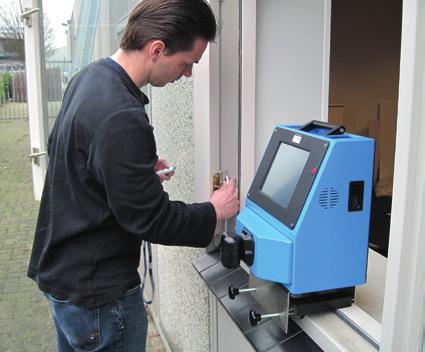
10 Getting started - Measure Project You can create a new Project and add information about the Project, such as customers name and address and operator. A Project can exist out of multiple measurements, all these measurements will have the same project information. File (measurement) You can create a new File (measurement) and add information about the File, such as material, parts and remarks. A file is part of a Project and will include the Project information and the file information. Settings In the grey box at the bottom of the screen you can see the current settings, these can be changed when pressing the Settings button. Start When everything is set, select: START A pop up screen will appear (shown right). It wants you to move the black measuring arm on the Proliner Up-Down and Left-Right. When finished you can start taking your measurements. When moving the arm horizontally and vertically, the wire should be completely retracted. To avoid pulling at the wire during the index search, hold the measuring arm and pen in one hand. Prodim CT 3.0 Version Copyright - Prodim International Page 10


11 Measuring screen Below the editing functions, there is a pull out menu that includes Projection, Compensation, Tolerance and Origin. Projection Selecting will allow you to change the projection settings on your Proliner. This is not often changed in a drawings because projection settings are set at the start of the drawing. Compensation Selecting will allow you to change your compensation from left to right, or none. It is best to choose the correct projection before starting the measurements. You can change the compensation for a contour, a layer or all. Tolerance Selecting will allow you to change the machine s tolerance. The default setting is set to the highest accuracy the Proliner can achieve. Changing the tolerance may result in less accurate drawings and more or fewer points. Origin This is the most important function in the menu. This function will allow you to set or change the x-axis of the drawing. It is often used to rotate the drawing for easier editing and exporting. To Use: Select the point to go in the lower left corner of the screen or select the point to go in the lower right corner of the screen. Zoom Pan Rotate Display settings View all Pan Move the measurement by pressing on the screen and moving it around. Zoom Zoom in by moving down on the screen and zoom out by moving up. Rotate Rotate the measurement by pressing the screen and moving around. Top view The measurement will be shown on top view for the selected layer. View all Shows the measurement exactly fitted on the screen. Display settings Various settings for what is displayed - see next page Top view Prodim CT 3.0 Version Copyright - Prodim International Page 11

12 Display settings Line Thickness Change the line thickness on screen. Contour Shows you the compensated measured contour. Element Ends Shows the end of every element in a contour. Raw Points Shows the raw 3D points, which are not interpolated and compensated. Dimensions Shows you the dimensions if you have them applied to the measurement, you can also change the font and arrow sizes of the dimensions Profiles Shows you the Profiles if you have them applied to the measurement Origin Shows the first measured point of the drawing which is always corresponding with the Origin. Machine Origin Shows the position of the Proliner during the measurement. Z-Lines Shows height-lines between the Raw Points and the 2D Contour. Identify First Contour Shows you the first contour as a light grey dashed line Show Leapfrog Shows the points taken for a leapfrog measurement (when present). Prodim CT 3.0 Version Copyright - Prodim International Page 12


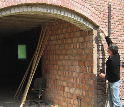
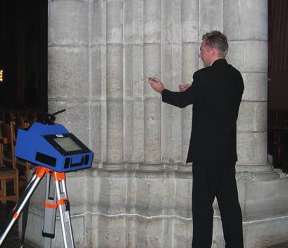
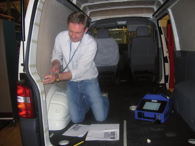
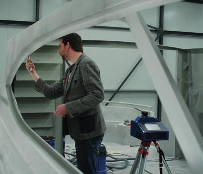
13 Moving the Proliner - Leap Leap - Relocating the proliner The Proliner Leap function was created to give user unlimited range when measuring large objects and spaces. Prodim developed special leap pods, which will be reference points to connect the measurements. Start your measurement as you would do it normally. Position your Proliner on a place where you can reach most of the parts of your object. In that case you need less measurements. When ready with that part, a Leap needs to be defined. When Leap is pressed the leap screen will appear. Here you can either create a new Leap or select to connect to an already defined Leap. You can then measure new leap points or select existing points in the current measurement. After selecting Measure new points you can insert a leap name and then define the points. Press Start Take the 4 points, as accurate as possible with button 1 on your remote Press Finish. Now the Proliner can be moved to the new position to finish the rest of the object. At the new position, start with Leap again. Choose in the dropdown box the Leap to which the drawing needs to be connected and press Connect. Press Start Take the 4 points again, as accurate as possible Check the misfit (If the misfit is within tolerance accept. Otherwise try to measure the leap again) Press Finish. Continue the measurement. These steps can be repeated as often as necessary. There are no limits. Rules of leapfrog measurement: The reference points must be positioned stable. The 4 points shouldn t be positioned: 1. too close to each other 2. in one line 3. in a symetric shape Prodim CT 3.0 Version Copyright - Prodim International Page 13

14 Editing Buttons Editing and checking drawings with the on-board CAD The editing buttons are grouped together to make search functions easier Select page 15 On-screen Dimensioning page 17 Measuring page 16 Editing page Import cut-outs page 23 Drawing page Undo / Redo page 22 Delete page 22 Snapshot page 22 Information PDF page Anytime a button has a white triangle in the lower left hand corner, that button has a drop down menu featuring more commands. To access the menu, push and hold down the editing button in that command group. Click on the to open an example movie of the function. Some of the functions share a movie and the other functions have their own example movie. indicates that there is not yet a movie available for this function. Prodim CT 3.0 Version Copyright - Prodim International Page 14
15 Editing Buttons The selection options Buttons in the select group are used to select single or multiple elements. The selected data is displayed as a thick red element in the grey toolbar. At the bottom of the screen you can deselect all at once. Multiple elements can be selected and the selected items can be colored, deleted or make snapshots. Select contour Select element Select layer Select window Select element Touch a single line to select it, touch a selected line to deselect it. Select window Drag over the screen, every complete element within the drag box will be selected. Select contour Touch a line from the contour to select the complete contour at once. Select layer Touch a line from the layer to select the complete layer at once. Prodim CT 3.0 Version Copyright - Prodim International Page 15

16 Editing Buttons The measuring options Buttons in the measuring group are used to verify accuracy and check dimensions. The measurement data is always displayed in the grey toolbar at the bottom of the screen. Measurements do not stay on screen when using these measuring buttons. Measure line Measure Angle Find Radius Measure Layer Angle Measure Chain Measure Z-Lines Measure Area Measure line Finds measurements of straight lines. To Use: Touch the end of the first line and touch the end of the second line. Different buttons are available for horizontal, vertical, and point to point dimensions. Find Radius Finds the radius of an arc. To Use: Touch the arc in question. The radius is shown in the grey box at the bottom of the screen. Measure Angle Lets you measure angles. To Use: Select the first line of the angle. Select another line of the angle. The angle is shown in the grey box at the bottom of the screen. Measure Layer Angle Lets you measure the angular difference between two layers. To Use: Select a point on the first layer. Select a point on the second layer. The angle is shown in the grey box at the bottom of the screen. Measure Chain Gives you the square inches of any closed shape on a single layer. To Use: Touch the closed contour in question. The square dimensions are shown in the grey box at the bottom of the screen. Measure Area Gives you the square inches of any closed shape on a single layer. To Use: Touch the closed contour in question. The square dimensions are shown in the grey box at the bottom of the screen. Measure Z-Lines Gives the length of the Z-lines. Shows the distance between actual points gathered and projected points on the layer. To Use: Select the command. This activates the z-lines. Touch the z-line in question. The distance is shown in the grey box at the bottom of the screen. Prodim CT 3.0 Version Copyright - Prodim International Page 16
17 Editing Buttons On-screen dimensioning Buttons in the on-screen dimensioning group are used to put visible data on your drawing. These dimensions will be visible on the PDF document exported from the Proliner. Line Dimensioning Radius Dimensioning Angle Dimensioning Line Dimensioning Puts measurements of straight lines on-screen. To Use: Touch the end of the first line and touch the end of the Second line. The third spot you will touch is the area where you want the measurement displayed. Different buttons are available for horizontal, vertical, and point to point dimensions. Radius Dimensioning Puts measurements of radii on-screen. To Use: Touch the radius line needed. Touch the area where you want the measurement displayed. Angle Dimensioning Puts measurements of angles on-screen. To Use: Touch the first line making the angle. Second, select the second line of the angle. Touch the area where you want the measurement displayed. Prodim CT 3.0 Version Copyright - Prodim International Page 17
18 Editing Buttons The editing options - part 1 Buttons in the editing group all make changes to existing lines. This includes joining, splitting, offsetting different points and lines within your drawings. Trim Fillet Split element Break on intersect Offset Offset points Trim Extends lines to their intersection and it trims off. To Use: Touch the end of the first line and touch the end of the second line. Fillet Rounds corners to a specific radius. To Use: Touch the end of the first line and touch the end of the Second line. Radius can be changed in the grey menu at the bottom of the screen. Offset Offsets lines to a specific distance. To Use: Touch near the line you want to offset, on the side and the direction you want the offset line. Touch again on the side you want to offset. Distance can be changed in the grey menu at the bottom of the screen. To keep the old line, check the box in the grey menu at the bottom of screen. Split element Splits a line evenly using the number of specified points. To Use: First determine the number of points you need and enter it into the grey menu at the bottom of the screen. Touch the line you want to add the points to. Offset points Splits a line using one point set to a specific distance. To Use: First determine the distance you want to offset the point and enter it into the grey menu at the bottom of the screen. Touch the line near the end you want to offset the point. Break on intersect Uses the intersection of two lines to break one line into two line segments. To Use: Select the line you want to break, then select the line you want to break it with. Prodim CT 3.0 Version Copyright - Prodim International Page 18

19 Editing Buttons The editing options - part 2 Buttons in the editing group all make changes to existing lines. This includes joining, splitting, offsetting different points and lines within your drawings. Tangential Extend line Layer name Modify Radius Color Profiles Tangential Create a perfect target to connect the elements. To Use: Touch the contour point that you want to make tangential. You can set the maximum deviation in the grey menu at the bottom of the screen. Extend line Extends one line so that it will intersect with another line. To Use: Select the line you want to extend, then select the line you want to extend to. Modify radius Tells you the radius of a curve. It also allows you to change the radius. To Use: Select the curve. The radius of the curve is displayed at the bottom of the screen. To change the radius, select the displayed radius and type in your new radius. Color Change the color of the line, contour or layer. To Use: Select the elements that you want to change. In the pop-up menu, choose your color. Then push the apply button. Layer name Change the name of layers in drawing. To Use: Select a line on that layer. Enter the new name. Select apply. Profiles Add a profile to the parts of your measurement. To Use: In the pop-up menu, choose your profile. Then push the Oke button. Select the elements that you want to change. Profiles are setup in the main Proliner screen in the setup menu. Profiles have names, colors and line thickness. Used Profiles will show up in a legenda on the PDF worksheet page Prodim CT 3.0 Version Copyright - Prodim International Page 19
20 Editing Buttons The drawing options - part 1 Buttons in the drawing group all create new geometry. This includes drawing lines, arcs, circles, rectangles and angles. Line Line perpendicular 2 Point Circle Level Line 3 Point Arc or Circle Draw Line at Angle Line Draws lines : horizontal, vertical, or point to point. To Use: Select a point where you want the point to start. Select the point where you want the line to end. In horizontal and vertical settings lines will snap to the correct axis. The axis is based on ORIGIN setting of the drawing. Line perpendicular Draws a line perpendicular to the adjacent line. To Use: Select the start point of your line. Select the line your point is on. Select the line you want the new line to extend to. Draw Line at Angle Draws a line at a specific angle. To Use: Enter the angle in the grey toolbar at the bottom. Select a line to use as a reference. Select a point on that line to act as a start point. Select the side of the line you want the angle to appear on. Level Line Draw a line on a drawing that shows a level reference. To Use: Select a start point. Select an end point. The line will be drawn in level to the ground in relation to the rest of the drawing. 3 Point Arc or Circle Uses at least 3 points to create an arc or circle. To Use: Select the start point of the arc. Select the end point of the arc. Select at least one point on the middle of the arc. (To draw a circle check full circle in the grey menu at the bottom of the screen). When finished select Apply. 2 Point Circle Uses 2 points to create a circle (center, radius). To Use: Select the point to be used as a midpoint. Select the point to be used as end of the radius. Select apply. Prodim CT 3.0 Version Copyright - Prodim International Page 20

21 Editing Buttons The drawing options - part 2 Buttons in the drawing group all create new geometry. This includes drawing lines, arcs, circles, rectangles and angles. External Rectangle Backsplash Bump-out Rectangle Bump-out Creates a bump-out at a specific distance using any 2 start points. To Use: Insert the desired distance in the grey bar at the bottom of the screen. Select the first start point. Select the second point (ending point). Touch the area of the screen you want the bump-out to appear. Backsplash Creates backsplash using any two points of the drawing. To Use: Insert the desired height in the grey bar at the bottom of the screen. Select the first start point. Select the second point (ending point). Selecting points in the same order they were measured puts the backsplash in the correct location in the drawing. If the backsplash appears on the wrong side, undo and select points in the opposite order. Rectangle Draws a rectangle with specific dimensions. To Use: Enter the width and height in the grey toolbar at the bottom. Touch for location and select apply in the grey toolbar at the bottom. External Rectangle Draws a minimum rectangle around the selected contour specific dimensions. To Use: Select elements and it automatically draws a minimal external box around it. Prodim CT 3.0 Version Copyright - Prodim International Page 21

22 Editing Buttons Import cut-out Undo / Redo Delete Snapshot Information PDF Import cut-out Import a PRL file (Proliner file) or DXF file in your current measurement. This function will be completely explained at page 23 Undo / Redo Go one step back or forward in your editing, multiple undo s are possible. To Use: Touch to Undo or to redo the a undo button. Snapshot Create a snapshot to create PDF worksheets. To Use: Select the elements you want for your single snapshot, for example select lines, contours and dimensions. Touch the snapshot button and fill in the name of the snapshot in the pop-up, click Oke. Delete Select single or multiple lines To Use: Select the parts you want to deleted. Information PDF Access your PDF worksheet pages. In the PDF information menu you can access all the snapshots made (multiple snapshots possible), add / edit project and measurement information. You can setup the exploded view and save options. This function will be futher explained on page Prodim CT 3.0 Version Copyright - Prodim International Page 22

23 Import cut-out Import cut-out Library Object Import Placement Method Offset Color Preview Library Pull-down menu which can contain multiple premade libraries with cut-outs to select from. Object Pull-down menu with the cut-outs that are present in the selected library. Import Instead of using a library you can also import a PRL file or DXF file from the Proliner or USB. Placement method Place a selected cut-out onto a centerline or use reference points to place the cut-out. Offset (centerline only) When using the centerline method you can set the distance from the front, this can be changed after importing in the grey bottom box, when using the reference points method you can move the imported object freely. Color Select the color you want the imported object to have in the measurement. Preview Shows you a preview of the object that you are going to import. Placing the object in the measurement After pressing Oke for location, select apply in the grey toolbar at the bottom. Before selecting apply you can move and rotate the object by selecting the option in the grey toolbar at the bottom. Prodim CT 3.0 Version Copyright - Prodim International Page 23

24 Information PDF Snapshots General settings Snapshot settings Snapshots The snapshots that you made will be shown on separate tabs. Exploded view Shows all the selected snapshots on one page Preview of the Exploded view on page 26. Overview Snapshots options. Explained on page 25. Project info Project information is shown on the PDF worksheet. Preview of the PDF worksheet is shown on page 27. Add or edit the information about the Project, such as the customer s name and address and operator. Measurement info Measurement information is shown on the PDF worksheet. Preview of the PDF worksheet is shown on page 27. Add or edit the information about the Project, such as material, parts and remarks. Sketch Gives you the main PDF information page, as shown above. Signature The Signature is shown on the PDF worksheet. With this function you can add disclaimer information and name. (You can let the client sign off a project immediately on the Proliner). PDF preview PDF worksheet pages. Shows you how the PDF worksheet will look like when its created. Note: the movie will show the complete PDF information function Prodim CT 3.0 Version Copyright - Prodim International Page 24

25 Information PDF OVERVIEW TAB In the overview tab you will get a list with all the available snapshots that you made. You can choose the following options: DXF Select to save the snapshot as a seperate CNC ready DXF file. PDF Page Select to save the snapshot with its own PDF worksheet. Explode View Select to show the snapshot on the explode view on the PDF worksheet. Rename Chance the name and the exported DXF name of the snapshot Remove Remove / delete the snapshot Freehand sketch When you have opened a snapshot you can use this pen to draw extra information. Touch the snapshot button and fill in the name. Delete elements Go one step back or forward in your editing, multiple undo s are possible. To Use: Press Undo to undo or to redo. Rename - option also available on the overview tab Select the name and the exported DXF file of the snapshot DXF - option also available on the overview tab Select to save the snapshot as a separate CNC ready DXF file. Remove - option also available on the overview tab Remove / delete the snapshot, when the option is selected the icon will be orange. PDF Page - option also available on the overview tab Select to save the snapshot with its own PDF worksheet, when the option is selected the icon will be orange. Expl. View- option also available on the overview tab Select to show the snapshot on the explode view on the PDF worksheet, when the option is checked the icon will be orange. Note: the movie will show the complete PDF information function Prodim CT 3.0 Version Copyright - Prodim International Page 25

26 Information PDF EXPLODED VIEW The selected snapshots are shown on the Exploded view page. You can select snapshots by clicking on them, they will be boxed and their name will be shown in the grey toolbar at the bottom. You can move the snapshots now freely and arrange the Exploded view. The exploded view will be visible on the PDF worksheet. Prodim CT 3.0 Version Copyright - Prodim International Page 26

27 Information PDF PDF PREVIEW - MAIN PAGE Exploded view Different PDF pages Project info Customer sign Measurement info PDF PREVIEW - SNAPSHOT SPECIFIC PAGE Prodim CT 3.0 Version Copyright - Prodim International Page 27


28 Prodim International BV P.O. Box AC Helmond, the Netherlands T: +31 (0) , F: +31 (0) a product of
PRODIM CT 3.2 & 3.3 MANUAL The Complete Solution
 PRODIM CT 3.2 & 3.3 MANUAL The Complete Solution We measure it all! General information Copyright All rights reserved. Apart from the legally laid down exceptions, no part of this publication may be reproduced,
AEROPLANE. Create a New Folder in your chosen location called Aeroplane. The four parts that make up the project will be saved here.
 AEROPLANE Prerequisite Knowledge Previous knowledge of the following commands is required to complete this lesson. Sketching (Line, Rectangle, Arc, Add Relations, Dimensioning), Extrude, Assemblies and
Introduction to Sheet Metal Features SolidWorks 2009
 SolidWorks 2009 Table of Contents Introduction to Sheet Metal Features Base Flange Method Magazine File.. 3 Envelopment & Development of Surfaces.. 14 Development of Transition Pieces.. 23 Conversion to
SolidWorks 95 User s Guide
 SolidWorks 95 User s Guide Disclaimer: The following User Guide was extracted from SolidWorks 95 Help files and was not originally distributed in this format. All content 1995, SolidWorks Corporation Contents
Lesson 6 2D Sketch Panel Tools
 Lesson 6 2D Sketch Panel Tools Inventor s Sketch Tool Bar contains tools for creating the basic geometry to create features and parts. On the surface, the Geometry tools look fairly standard: line, circle,
Constructing a Wedge Die
 1-(800) 877-2745 www.ashlar-vellum.com Using Graphite TM Copyright 2008 Ashlar Incorporated. All rights reserved. C6CAWD0809. Ashlar-Vellum Graphite This exercise introduces the third dimension. Discover
The Revolve Feature and Assembly Modeling
 The Revolve Feature and Assembly Modeling PTC Clock Page 52 PTC Contents Introduction... 54 The Revolve Feature... 55 Creating a revolved feature...57 Creating face details... 58 Using Text... 61 Assembling
SolidWorks Design & Technology
 SolidWorks Design & Technology Training Course at PHSG Ex 5. Lego man Working with part files 8mm At first glance the Lego man looks complicated but I hope you will see that if you approach a project one
Activity 1 Modeling a Plastic Part
 Activity 1 Modeling a Plastic Part In this activity, you will model a plastic part. When completed, your plastic part should look like the following two illustrations. While building this model, take time
User Guide V10 SP1 Addendum
 Alibre Design User Guide V10 SP1 Addendum Copyrights Information in this document is subject to change without notice. The software described in this document is furnished under a license agreement or
Using Siemens NX 11 Software. The connecting rod
 Using Siemens NX 11 Software The connecting rod Based on a Catia tutorial written by Loïc Stefanski. At the end of this manual, you should obtain the following part: 1 Introduction. Start NX 11 and open
Toothbrush Holder. A drawing of the sheet metal part will also be created.
 Prerequisite Knowledge Previous knowledge of the following commands is required to complete this lesson; Sketch (Line, Centerline, Circle, Add Relations, Smart Dimension,), Extrude Boss/Base, and Edit
How to Build a Game Console. David Hunt, PE
 How to Build a Game Console David Hunt, PE davidhunt@outdrs.net Covering: Drafts Fillets Shells Patterns o Linear o Circular Using made-for-the-purpose sketches to define reference geometry Using reference
SolidWorks Part I - Basic Tools SDC. Includes. Parts, Assemblies and Drawings. Paul Tran CSWE, CSWI
 SolidWorks 2015 Part I - Basic Tools Includes CSWA Preparation Material Parts, Assemblies and Drawings Paul Tran CSWE, CSWI SDC PUBLICATIONS Better Textbooks. Lower Prices. www.sdcpublications.com Powered
Module 1G: Creating a Circle-Based Cylindrical Sheet-metal Lateral Piece with an Overlaying Lateral Edge Seam And Dove-Tail Seams on the Top Edge
 Inventor (10) Module 1G: 1G- 1 Module 1G: Creating a Circle-Based Cylindrical Sheet-metal Lateral Piece with an Overlaying Lateral Edge Seam And Dove-Tail Seams on the Top Edge In Module 1A, we have explored
Name: Date Completed: Basic Inventor Skills I
 Name: Date Completed: Basic Inventor Skills I 1. Sketch, dimension and extrude a basic shape i. Select New tab from toolbar. ii. Select Standard.ipt from dialogue box by double clicking on the icon. iii.
Module 2: Radial-Line Sheet-Metal 3D Modeling and 2D Pattern Development: Right Cone (Regular, Frustum, and Truncated)
") Inventor (5) Module 2: 2-1 Module 2: Radial-Line Sheet-Metal 3D Modeling and 2D Pattern Development: Right Cone (Regular, Frustum, and Truncated) In this tutorial, we will learn how to build a 3D model
Inventor (5) Module 2: 2-1 Module 2: Radial-Line Sheet-Metal 3D Modeling and 2D Pattern Development: Right Cone (Regular, Frustum, and Truncated) In this tutorial, we will learn how to build a 3D model
Module 1C: Adding Dovetail Seams to Curved Edges on A Flat Sheet-Metal Piece
 1 Module 1C: Adding Dovetail Seams to Curved Edges on A Flat Sheet-Metal Piece In this Module, we will explore the method of adding dovetail seams to curved edges such as the circumferential edge of a
Learning Guide. ASR Automated Systems Research Inc. # Douglas Crescent, Langley, BC. V3A 4B6. Fax:
 Learning Guide ASR Automated Systems Research Inc. #1 20461 Douglas Crescent, Langley, BC. V3A 4B6 Toll free: 1-800-818-2051 e-mail: support@asrsoft.com Fax: 604-539-1334 www.asrsoft.com Copyright 1991-2013
Introduction to Autodesk Inventor for F1 in Schools (Australian Version)
") Introduction to Autodesk Inventor for F1 in Schools (Australian Version) F1 in Schools race car In this course you will be introduced to Autodesk Inventor, which is the centerpiece of Autodesk s Digital
Introduction to Autodesk Inventor for F1 in Schools (Australian Version) F1 in Schools race car In this course you will be introduced to Autodesk Inventor, which is the centerpiece of Autodesk s Digital
Module 1H: Creating an Ellipse-Based Cylindrical Sheet-metal Lateral Piece
 Inventor (10) Module 1H: 1H- 1 Module 1H: Creating an Ellipse-Based Cylindrical Sheet-metal Lateral Piece In this Module, we will learn how to create an ellipse-based cylindrical sheetmetal lateral piece
Inventor-Parts-Tutorial By: Dor Ashur
 Inventor-Parts-Tutorial By: Dor Ashur For Assignment: http://www.maelabs.ucsd.edu/mae3/assignments/cad/inventor_parts.pdf Open Autodesk Inventor: Start-> All Programs -> Autodesk -> Autodesk Inventor 2010
Evaluation Chapter by CADArtifex
 The premium provider of learning products and solutions www.cadartifex.com EVALUATION CHAPTER 2 Drawing Sketches with SOLIDWORKS In this chapter: Invoking the Part Modeling Environment Invoking the Sketching
Kitchen and Bath Design Tutorial
 Kitchen and Bath Design Tutorial This tutorial continues where the Interior Design Tutorial left off. You should save this tutorial using a new name to archive your previous work. The tools and techniques
Alternatively, the solid section can be made with open line sketch and adding thickness by Thicken Sketch.
 Sketcher All feature creation begins with two-dimensional drawing in the sketcher and then adding the third dimension in some way. The sketcher has many menus to help create various types of sketches.
Modeling an Airframe Tutorial
 EAA SOLIDWORKS University p 1/11 Difficulty: Intermediate Time: 1 hour As an Intermediate Tutorial, it is assumed that you have completed the Quick Start Tutorial and know how to sketch in 2D and 3D. If
Inventor Activity 5: Lofted Vase
 Inventor Activity 5: Lofted Vase In this tutorial, you will use a few new commands to create a free form Lofted object. Sometimes you want to create an object that is not made up of square, flat, or perfectly
Creo Revolve Tutorial
 Creo Revolve Tutorial Setup 1. Open Creo Parametric Note: Refer back to the Creo Extrude Tutorial for references and screen shots of the Creo layout 2. Set Working Directory a. From the Model Tree navigate
Beginner s Guide to SolidWorks Alejandro Reyes, MSME Certified SolidWorks Professional and Instructor SDC PUBLICATIONS
 Beginner s Guide to SolidWorks 2008 Alejandro Reyes, MSME Certified SolidWorks Professional and Instructor SDC PUBLICATIONS Schroff Development Corporation www.schroff.com www.schroff-europe.com Part Modeling
Drawing with precision
 Drawing with precision Welcome to Corel DESIGNER, a comprehensive vector-based drawing application for creating technical graphics. Precision is essential in creating technical graphics. This tutorial
Digital Camera Exercise
 Commands Used New Part This lesson includes Sketching, Extruded Boss/Base, Extruded Cut, Fillet, Chamfer and Text. Click File, New on the standard toolbar. Select Part from the New SolidWorks Document
Revit Structure 2012 Basics:
 SUPPLEMENTAL FILES ON CD Revit Structure 2012 Basics: Framing and Documentation Elise Moss autodesk authorized publisher SDC PUBLICATIONS www.sdcpublications.com Schroff Development Corporation Structural
for Solidworks TRAINING GUIDE LESSON-9-CAD
 for Solidworks TRAINING GUIDE LESSON-9-CAD Mastercam for SolidWorks Training Guide Objectives You will create the geometry for SolidWorks-Lesson-9 using SolidWorks 3D CAD software. You will be working
Kitchen and Bath Design Tutorial
 Kitchen and Bath Design Tutorial This tutorial continues where the Interior Design Tutorial left off. You should save this tutorial using a new name to archive your previous work. The tools and techniques
Table of Contents. Lesson 1 Getting Started
 NX Lesson 1 Getting Started Pre-reqs/Technical Skills Basic computer use Expectations Read lesson material Implement steps in software while reading through lesson material Complete quiz on Blackboard
Introduction to CATIA V5
 Introduction to CATIA V5 Release 17 (A Hands-On Tutorial Approach) Kirstie Plantenberg University of Detroit Mercy SDC PUBLICATIONS Schroff Development Corporation www.schroff.com Better Textbooks. Lower
Autodesk Inventor Module 17 Angles
 Inventor Self-paced ecourse Autodesk Inventor Module 17 Angles Learning Outcomes When you have completed this module, you will be able to: 1 Describe drawing inclined lines, aligned and angular dimensions,
Apple Photos Quick Start Guide
 Apple Photos Quick Start Guide Photos is Apple s replacement for iphoto. It is a photograph organizational tool that allows users to view and make basic changes to photos, create slideshows, albums, photo
Anna Gresham School of Landscape Design. CAD for Beginners. CAD 3: Using the Drawing Tools and Blocks
 Anna Gresham School of Landscape Design CAD for Beginners CAD 3: Using the Drawing Tools and Blocks Amended for DraftSight V4 October 2013 INDEX OF TOPICS for CAD 3 Pages ESnap 3-5 Essential drawing tools
COPRA 2002 is coming with 69 new features
 COPRA is coming with 69 new features are marked with COPRA is available for AutoCAD 14 / Mechanical Desktop 3 AutoCAD 2000 / Mechanical Desktop 4 AutoCAD 2000i / Mechanical Desktop 5 AutoCAD / Mechanical
Introduction to SolidWorks Introduction to SolidWorks
 Introduction to SolidWorks Introduction to SolidWorks SolidWorks is a powerful 3D modeling program. The models it produces can be used in a number of ways to simulate the behaviour of a real part or assembly
Chapter 6 Title Blocks
 Chapter 6 Title Blocks In previous exercises, every drawing started by creating a number of layers. This is time consuming and unnecessary. In this exercise, we will start a drawing by defining layers
Sketch-Up Guide for Woodworkers
 W Enjoy this selection from Sketch-Up Guide for Woodworkers In just seconds, you can enjoy this ebook of Sketch-Up Guide for Woodworkers. SketchUp Guide for BUY NOW! Google See how our magazine makes you
FUSION 360: SKETCHING FOR MAKERS
 FUSION 360: SKETCHING FOR MAKERS LaDeana Dockery 2017 MAKEICT Wichita, KS 1 Table of Contents Interface... 1 File Operations... 1 Opening Existing Models... 1 Mouse Navigation... 1 Preferences... 2 Navigation
Getting Started. Right click on Lateral Workplane. Left Click on New Sketch
 Getting Started 1. Open up PTC Pro/Desktop by either double clicking the icon or through the Start button and in Programs. 2. Once Pro/Desktop is open select File > New > Design 3. Close the Pallet window
Tutorial Building the Nave Arcade
 Tutorial: Digital Gothic AH C117B (Winter 2017) Tutorial Building the Nave Arcade Overview: Step 1: Determining and Drawing The Arch (Quinto Arch) Step 2: Extrude Molding Profile Step 3: Adding Walls Step
AutoCAD Tutorial First Level. 2D Fundamentals. Randy H. Shih SDC. Better Textbooks. Lower Prices.
 AutoCAD 2018 Tutorial First Level 2D Fundamentals Randy H. Shih SDC PUBLICATIONS Better Textbooks. Lower Prices. www.sdcpublications.com Powered by TCPDF (www.tcpdf.org) Visit the following websites to
TUTORIAL 4: Combined Axial and Bending Problem Sketch Path Sweep Initial Project Space Setup Static Structural ANSYS
 TUTORIAL 4: Combined Axial and Bending Problem In this tutorial you will learn how to draw a bar that has bends along its length and therefore will have both axial and bending stresses acting on cross-sections
Advance Dimensioning and Base Feature Options
 Chapter 4 Advance Dimensioning and Base Feature Options Learning Objectives After completing this chapter you will be able to: Dimension the sketch using the autodimension sketch tool. Dimension the sketch
Engineering & Computer Graphics Workbook Using SolidWorks 2014
 Engineering & Computer Graphics Workbook Using SolidWorks 2014 Ronald E. Barr Thomas J. Krueger Davor Juricic SDC PUBLICATIONS Better Textbooks. Lower Prices. www.sdcpublications.com Powered by TCPDF (www.tcpdf.org)
Getting Started. with Easy Blue Print
 Getting Started with Easy Blue Print User Interface Overview Easy Blue Print is a simple drawing program that will allow you to create professional-looking 2D floor plan drawings. This guide covers the
1: INTRODUCTION TO AUTOCAD
 AutoCAD syllabus 1: INTRODUCTION TO AUTOCAD Starting AutoCAD AutoCAD Screen Components Drawing Area Command Window Navigation bar Status bar Invoking Commands in AutoCAD Keyboard Ribbon Application Menu
CAD/CAM Lamp Project using 2D Design and the X-660 Laser Cutter
 CAD/CAM Lamp Project using 2D Design and the X-660 Laser Cutter Paul Tate 2008 Booklet Version 2 Getting Started the preliminaries The Laser cutter which is going to cut out your acrylic bases and polypropylene
Engineering & Computer Graphics Workbook Using SOLIDWORKS
 Engineering & Computer Graphics Workbook Using SOLIDWORKS 2017 Ronald E. Barr Thomas J. Krueger Davor Juricic SDC PUBLICATIONS Better Textbooks. Lower Prices. www.sdcpublications.com Powered by TCPDF (www.tcpdf.org)
Conquering the Rubicon
 Autodesk Inventor R10 Fundamentals: Conquering the Rubicon Elise Moss SDC PUBLICATIONS Schroff Development Corporation www.schroff.com www.schroff-europe.com Schroff Development Corporation P.O. Box 1334
MasterCAM for Dresser Valet
 MasterCAM for Dresser Valet Check to make sure the nethasp is working/turned on to network. Go to ALL APPs/Mastercam x8/nethasp After the computer reads the nethasp, these programs should show up. If not
Modeling Basic Mechanical Components #1 Tie-Wrap Clip
 Modeling Basic Mechanical Components #1 Tie-Wrap Clip This tutorial is about modeling simple and basic mechanical components with 3D Mechanical CAD programs, specifically one called Alibre Xpress, a freely
1. Reference Guide and Glossary
 1. Reference Guide and Glossary Design Panel New Click the New Icon at any time to create a new project from scratch. Projects Browse, select, and cut projects from the Projects Tab. This includes your
Part 8: The Front Cover
 Part 8: The Front Cover 4 Earpiece cuts and housing Lens cut and housing Microphone cut and housing The front cover is similar to the back cover in that it is a shelled protrusion with screw posts extruding
Alibre Design Exercise Manual Introduction to Sheet Metal Design
 Alibre Design Exercise Manual Introduction to Sheet Metal Design Copyrights Information in this document is subject to change without notice. The software described in this documents is furnished under
Making Standard Note Blocks and Placing the Bracket in a Drawing Border
 C h a p t e r 12 Making Standard Note Blocks and Placing the Bracket in a Drawing Border In this chapter, you will learn the following to World Class standards: Making standard mechanical notes Using the
Siemens NX11 tutorials. The angled part
 Siemens NX11 tutorials The angled part Adaptation to NX 11 from notes from a seminar Drive-to-trial organized by IBM and GDTech. This tutorial will help you design the mechanical presented in the figure
CREO.1 MODELING A BELT WHEEL
 CREO.1 MODELING A BELT WHEEL Figure 1: A belt wheel modeled in this exercise. Learning Targets In this exercise you will learn: Using symmetry when sketching Using pattern to copy features Using RMB when
Engineering Technology
 Engineering Technology Introduction to Parametric Modelling Engineering Technology 1 See Saw Exercise Part 1 Base Commands used New Part This lesson includes Sketching, Extruded Boss/Base, Hole Wizard,
Product Modelling in Solid Works
 Product Modelling in Solid Works In the following exercise you will use solid works to construct the computer mouse shown opposite. In this exercise you will use a number of advanced features to achieve
Foreword. If you have any questions about these tutorials, drop your mail to
 Foreword The main objective of these tutorials is to give you a kick start using Solidworks. The approach to write this tutorial is based on what is the most important knowledge you should know and what
Autodesk AutoCAD 2013 Fundamentals
 Autodesk AutoCAD 2013 Fundamentals Elise Moss SDC P U B L I C AT I O N S Schroff Development Corporation Better Textbooks. Lower Prices. www.sdcpublications.com Visit the following websites to learn more
EASY CNC. Table of Contents
 Square 1 Electronics announces its new book by David Benson, "Easy CNC", A Beginner's Guide to CNC" The complete table of contents follows: This book was written by David Benson (8-1/2 x 11", 200 pages,
CAD Tutorial 24: Step by Step Guide
 CAD TUTORIAL 24: Step by step CAD Tutorial 24: Step by Step Guide Level of Difficulty Time Approximately 40 50 minutes Lesson Objectives To understand the basic tools used in SketchUp. To understand the
1 Best Practices Course Week 12 Part 2 copyright 2012 by Eric Bobrow. BEST PRACTICES COURSE WEEK 12 PART 2 Program Planning Areas and Lists of Spaces
 BEST PRACTICES COURSE WEEK 12 PART 2 Program Planning Areas and Lists of Spaces Hello, this is Eric Bobrow. And in this lesson, we'll take a look at how you can create a site survey drawing in ArchiCAD
AutoCAD Lab 1 Basics and Drawing Fundamentals. EGS 1007 Engineering Concepts and Methods
 AutoCAD Lab 1 Basics and Drawing Fundamentals EGS 1007 Engineering Concepts and Methods Will the Computer Ever REPLACE Pencil and Paper Drawings? Maybe someday When a computer becomes as light, small,
Autodesk Advance Steel. Drawing Style Manager s guide
 Autodesk Advance Steel Drawing Style Manager s guide TABLE OF CONTENTS Chapter 1 Introduction... 5 Details and Detail Views... 6 Drawing Styles... 6 Drawing Style Manager... 8 Accessing the Drawing Style
with Creo Parametric 4.0
 Parametric Modeling with Creo Parametric 4.0 An Introduction to Creo Parametric 4.0 NEW Contains a new chapter on 3D Printing Randy H. Shih SDC PUBLICATIONS Better Textbooks. Lower Prices. www.sdcpublications.com
SDC. SolidWorks Tutorial 2001Plus. A Competency Project Based Approach Utilizing 3D Solid Modeling. David C. Planchard & Marie P.
 2001Plus A Competency Project Based Approach Utilizing 3D Solid Modeling David C. Planchard & Marie P. Planchard SDC PUBLICATIONS www.schroff.com www.schroff-europe.com Project 2 Below are the desired
Ornamental Pro 2004 Instruction Manual (Drawing Basics)
") Ornamental Pro 2004 Instruction Manual (Drawing Basics) http://www.ornametalpro.com/support/techsupport.htm Introduction Ornamental Pro has hundreds of functions that you can use to create your drawings.
Ornamental Pro 2004 Instruction Manual (Drawing Basics) http://www.ornametalpro.com/support/techsupport.htm Introduction Ornamental Pro has hundreds of functions that you can use to create your drawings.
1. Create a 2D sketch 2. Create geometry in a sketch 3. Use constraints to position geometry 4. Use dimensions to set the size of geometry
 2.1: Sketching Many features that you create in Fusion 360 start with a 2D sketch. In order to create intelligent and predictable designs, a good understanding of how to create sketches and how to apply
Principles and Applications of Microfluidic Devices AutoCAD Design Lab - COMSOL import ready
 Principles and Applications of Microfluidic Devices AutoCAD Design Lab - COMSOL import ready Part I. Introduction AutoCAD is a computer drawing package that can allow you to define physical structures
DRAFT Solid Edge ST4 Update Training Draft
 DRAFT Solid Edge ST4 Update Training Draft Presented by: Steve Webb Topics Parts List Table Titles Column Headers Headers Merging Header Rotate Cell Aspect Ratio Cell Formatting Overriding Disabled Cells
06/17/02 Page 1 of 12
 Understanding the Graphical User Interface When you start AutoCAD, the AutoCAD window opens. The window is your design work space. It contains elements that you use to create your designs and to receive
Introduction to Circular Pattern Flower Pot
 Prerequisite Knowledge Previous knowledge of the sketching commands Line, Circle, Add Relations, Smart Dimension is required to complete this lesson. Previous examples of Revolved Boss/Base, Cut Extrude,
Architecture 2012 Fundamentals
 Autodesk Revit Architecture 2012 Fundamentals Supplemental Files SDC PUBLICATIONS Schroff Development Corporation Better Textbooks. Lower Prices. www.sdcpublications.com Tutorial files on enclosed CD Visit
Advance Steel. Drawing Style Manager s guide
 Advance Steel Drawing Style Manager s guide TABLE OF CONTENTS Chapter 1 Introduction...7 Details and Detail Views...8 Drawing Styles...8 Drawing Style Manager...9 Accessing the Drawing Style Manager...9
Create A Mug. Skills Learned. Settings Sketching 3-D Features. Revolve Offset Plane Sweep Fillet Decal* Offset Arc
 Create A Mug Skills Learned Settings Sketching 3-D Features Slice Line Tool Offset Arc Revolve Offset Plane Sweep Fillet Decal* Tutorial: Creating A Custom Mug There are somethings in this world that have
Converting a solid to a sheet metal part tutorial
 Converting a solid to a sheet metal part tutorial Introduction Sometimes it is easier to start with a solid and convert it to create a sheet metal part. This tutorial will guide you through the process
Figure 1: NC Lathe menu
 Click To See: How to Use Online Documents SURFCAM Online Documents 685)&$0Ã5HIHUHQFHÃ0DQXDO 5 /$7+( 5.1 INTRODUCTION The lathe mode is used to perform operations on 2D geometry, turned on two axis lathes.
Basic 2D drawing skills in AutoCAD 2017
 Basic 2D drawing skills in AutoCAD 2017 This Tutorial is going to teach you the basic functions of AutoCAD and make you more efficient with the program. Follow all the steps so you can learn all the skills.
Main screen of ipocket Draw
 Main screen of ipocket Draw The tools of "management" Informations on the drawing and the softaware Display/Hide and settings of the grid (with a 2x tap) Drawing tools and adjustment tools The tools with..
Isometric Drawings. Figure A 1
 A Isometric Drawings ISOMETRIC BASICS Isometric drawings are a means of drawing an object in picture form for better clarifying the object s appearance. These types of drawings resemble a picture of an
ILLUSTRATOR BASICS FOR SCULPTURE STUDENTS. Vector Drawing for Planning, Patterns, CNC Milling, Laser Cutting, etc.
 ILLUSTRATOR BASICS FOR SCULPTURE STUDENTS Vector Drawing for Planning, Patterns, CNC Milling, Laser Cutting, etc. WELCOME TO THE ILLUSTRATOR TUTORIAL FOR SCULPTURE DUMMIES! This tutorial sets you up for
AutoCAD 2018 Fundamentals
 Autodesk AutoCAD 2018 Fundamentals Elise Moss SDC PUBLICATIONS Better Textbooks. Lower Prices. www.sdcpublications.com Powered by TCPDF (www.tcpdf.org) Visit the following websites to learn more about
SDC. AutoCAD LT 2007 Tutorial. Randy H. Shih. Schroff Development Corporation Oregon Institute of Technology
 AutoCAD LT 2007 Tutorial Randy H. Shih Oregon Institute of Technology SDC PUBLICATIONS Schroff Development Corporation www.schroff.com www.schroff-europe.com AutoCAD LT 2007 Tutorial 1-1 Lesson 1 Geometric
1.6.7 Add Arc Length Dimension Modify Dimension Value Check the Sketch Curve Connectivity
 Contents 2D Sketch... 1 1.1 2D Sketch Introduction... 1 1.1.1 2D Sketch... 1 1.1.2 Basic Setting of 2D Sketch... 2 1.1.3 Exit 2D Sketch... 4 1.2 Draw Common Geometry... 5 2.2.1 Points... 5 2.2.2 Lines
Appendix B: Autocad Booklet YR 9 REFERENCE BOOKLET ORTHOGRAPHIC PROJECTION
 Appendix B: Autocad Booklet YR 9 REFERENCE BOOKLET ORTHOGRAPHIC PROJECTION To load Autocad: AUTOCAD 2000 S DRAWING SCREEN Click the start button Click on Programs Click on technology Click Autocad 2000
ME Week 2 Project 2 Flange Manifold Part
 1 Project 2 - Flange Manifold Part 1.1 Instructions This project focuses on additional sketching methods and sketching commands. Revolve and Work features are also introduced. The part being modeled is
10/14/2010. Chevy Malibu. Vehicle Design with Solidworks. Start SolidWorks Create a New SolidWorks Document. Miles, Rowardo B
 Chevy Malibu Vehicle Design with Solidworks Start SolidWorks Create a New SolidWorks Document Miles, Rowardo B 1 Click: Part and then OK Now you are ready to make a Part. 2 Right Toolbar: Document Properties:
Introduction To Modeling
 Introduction To Modeling Introduction ProEngineer Wildfire2 is a computer aided design (CAD) program that is used to create models on a computer in three-dimensions. Since three dimensions are used the