Aircraft Drawing and Blueprint Reading
|
|
|
- Joshua Phelps
- 6 years ago
- Views:
Transcription

1 Aircraft Drawing and Blueprint Reading
2 Course Introduction Types of drawings Engineering also known as production or working drawings. Block diagram
3 Types of Drawings Schematics Sketches Charts and graphs
4 Production Drawings Detail Assembly Installation
5 Detail Drawing Consists of one part or several parts of an assembly. Contains all the specs needed to make the part.

6 Assembly Drawing Shows how parts from detail drawings are assembled to form a component. Does not show dimensions except those necessary for location purposes. Cut-Away View

7 Exploded View Assembly Drawing
8 Installation Drawing Shows how a part or component is installed in the aircraft. Location and directional dimensions are included.

9 Block Diagrams Used to simplify complex circuits Shows the function and relationships of various components within a system.
10 Schematics Like block diagrams, they are used to explain a system. More detailed than a block diagram.
11 Schematics Not all schematics are electrical
12 Sketches Anything from a scribble on a cocktail napkin to a detailed engineering drawing. One should strive to develop the skill to produce a rendering that is as accurate and clean as possible.
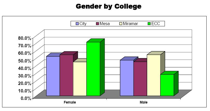
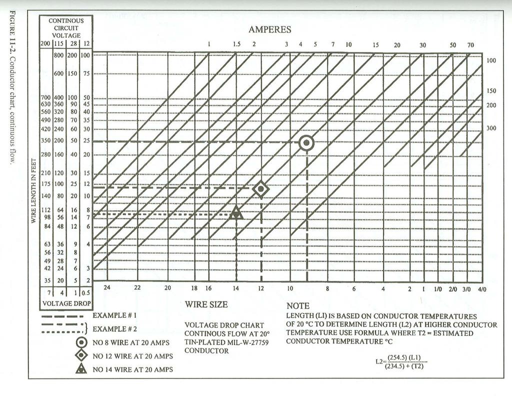
13 Charts and Graphs Are used to aid in the presentation of data, especially mathematical data.
14 Charts and Graphs Charts and graphs help in the understanding of aircraft operations and can sometime offer shortcuts to mathematical calculations.
15 Lettering Accurate and legible drawings require uniform and legible lettering. Lettering should receive the same attention to detail as does the drawing itself.
16 Lettering Each letter should be 6 units high. All letters are either 5 or 6 units wide. The exceptions are I, which has no width, and W, which is the widest letter of the alphabet.
17 Lettering Those letters that are 6 units wide make up the name TOM Q VAXY All others, with the exception of I and W, are 5 units wide. W is 8 units wide and I is one unit wide.
18 Lettering Do not space letters equal distances apart. Space by eye so that the background areas between the letters appear equal.
19 Projections and Lines Projections help us to see a 3-dimensional object using a 2-dimensional medium. Different views are used to highlight different objectives for each drawing.
20 Types of Projections Perspective drawings In a perspective drawing parallel lines are shown converging as they recede into the picture. This effect is known as foreshortening
21 Types of Projections Not accurate for dimensioning, perspective drawings are used for overall views and providing location information.
22 Types of Projections Oblique views Parallel lines are parallel and dimensions of sides are accurate. Front face is drawn in true size and shape.
23 Types of Projections Isometric projections Similar to oblique views but not as distorted. Horizontal lines are drawn at a 45 or 30 /60 angle.
24 Types of Projections Orthographic projections Presents an object using a series of views from different sides. Front, top, and right side views are most common.
25 Three widths of lines used - wide, medium, and narrow Lines
26 Dimensioning Used for determining the size or location of an object. Indicated by numbers followed by units of dimension e.g. ft, mm, etc.
27 Dimensioning If no unit is present then the dimension is in inches. Dimensions may be in decimal form or in fractions.
28 Dimensioning Tolerance total permissible variation in size. (+) and (-) signs are used, followed by the dimension, either in units or %. Example:.005 inches or 5%
29 Dimensioning Allowance prescribed difference between the maximum material limits of mating parts. Classes of fit from positive (loose or sliding) to negative (tight or interference).
30 Dimensioning Placement of dimensions Draw the dimension line outside of the object, if possible. Correct Incorrect
31 Dimensioning Draw the shortest dimension lines closest to the object and the longest lines furthest away.
32 Orthographic Projections Using different views to look head-on at each side of an object. The number of views are dictated by the complexity of the object.
33 Orthographic Projections Anywhere from one to six views are possible. Front, top, right side, left side, rear, bottom.
34 Orthographic Projection Most common: Single view front 2 view front, top 3 view front, top, right side Sides are referenced from the front, as you look at it.
35 Orthographic Projections Only those views needed to describe the object s shape should be drawn. Views should be laid out in a standardized fashion, with proper spacing and alignment among the views.
36 Drawing 3-Views Any given point in the drawing will show in all views.
37 Drawing 3-Views Lines that coincide. A solid line covers a hidden line.
38 Drawing 3-Views A solid line covers a centerline. A hidden line covers a centerline.
39 Drawing Three-views Adding a Title Box Place in Lower right corner ½ from the edge
40 Isometric Projections An effective way to sketch an object pictorially. Object is dimensionally correct but has some distortion in viewing.
41 Maximum Material Condition Definition: a part manufactured to the limit of its tolerance which leaves the most material on the part. MMC is often used to determine the fit of two interconnecting parts in their closest tolerance
42 Maximum Material Condition Example 1: a dowel whose diameter is ±.005 would have a maximum material condition of 1.005
43 Maximum Material Condition Example 2: a hole in a part whose diameter is ±.005 would have a maximum material condition of 0.995
44 Allowance Definition: the difference in dimension between the maximum material conditions of two interconnecting parts Allowance can be positive (clearance fit) or negative (interference fit).
45 Allowance
46 Spacing Holes
47 Locating bolt holes without a protractor
48 Charts
49

50 Graphs
51 Graphs
52 Graphs

53
54
11/12/2015 CHAPTER 7. Axonometric Drawings (cont.) Axonometric Drawings (cont.) Isometric Projections (cont.) 1) Axonometric Drawings
 Axonometric Drawings (cont.) Isometric Projections (cont.) 1) Axonometric Drawings") CHAPTER 7 1) Axonometric Drawings 1) Introduction Isometric & Oblique Projection Axonometric projection is a parallel projection technique used to create a pictorial drawing of an object by rotating the
CHAPTER 7 1) Axonometric Drawings 1) Introduction Isometric & Oblique Projection Axonometric projection is a parallel projection technique used to create a pictorial drawing of an object by rotating the
Student Name: Teacher: Date: District: Rowan. Assessment: 9_12 T and I IC61 - Drafting I Test 1. Description: Unit C - Sketching - Test 2.
 Student Name: Teacher: Date: District: Rowan Assessment: 9_12 T and I IC61 - Drafting I Test 1 Description: Unit C - Sketching - Test 2 Form: 501 1. The most often used combination of views includes the:
UNIT 5a STANDARD ORTHOGRAPHIC VIEW DRAWINGS
 UNIT 5a STANDARD ORTHOGRAPHIC VIEW DRAWINGS 5.1 Introduction Orthographic views are 2D images of a 3D object obtained by viewing it from different orthogonal directions. Six principal views are possible
Elementary Dimensioning
 Elementary Dimensioning Standards Institutions ANSI - American National Standards Institute - creates the engineering standards for North America. ISO - International Organization for Standardization -
1. When sketching long, narrow objects in OBLIQUE, distortion can be lessened by placing the long dimension along:
 Draft Student Name: Teacher: District: Date: Wake County Test: 9_12 T and I IC61 - Drafting I Test 2 Description: 3.03 Apply 3D sketching Form: 501 1. When sketching long, narrow objects in OBLIQUE, distortion
Beginning Engineering Graphics 3 rd Week Lecture Notes Instructor: Edward N. Locke Topic: The Coordinate System, Types of Drawings and Orthographic
 Beginning Engineering Graphics 3 rd Week Lecture Notes Instructor: Edward N. Locke Topic: The Coordinate System, Types of Drawings and Orthographic 1 st Subject: The Cartesian Coordinate System The Cartesian
MULTIPLE CHOICE QUESTIONS - CHAPTER 6
 MULTIPLE CHOICE QUESTIONS - CHAPTER 6 1. The selection of the front view in executing a multiview drawing of an object is dependent upon the following factors: a. size and shape of the object and their
Pictorial Drawings. DFTG-1305 Technical Drafting Prepared by Francis Ha, Instructor
 DFTG-1305 Technical Drafting Prepared by Francis Ha, Instructor Pictorial Drawings Geisecke s textbook for reference: 14 th Ed. Ch. 15: p. 601 Ch. 16: p. 620 15 th Ed. Ch. 14: p. 518 Ch. 15: p. 552 Update:
ENGR 1182 Exam 1 First Mid Term Exam Study Guide and Practice Problems
 Spring Semester 2016 ENGR 1182 Exam 1 First Mid Term Exam Study Guide and Practice Problems Disclaimer Problems in this study guide resemble problems relating mainly to the pertinent homework assignments.
the same information given in two different 1. Dimensions should NOT be duplicated, or Dimension Guidelines Incorrect ways.
 Dimension Guidelines 1. Dimensions should NOT be duplicated, or the same information given in two different ways. Incorrect 1. Dimensions should NOT be duplicated, or the same information given in two
Technological Design Mr. Wadowski. Orthographic & Isometric Drawing Lesson
 Technological Design Mr. Wadowski Orthographic & Isometric Drawing Lesson TOPICS Working Drawings, Isometric Drawings & Orthographic Drawings Glass box concept Multiview projection Orthographic projection
CAD Mechanical Design I
 EXAM INFORMATION Items 58 Points 85 Prerequisites NONE Course Length ONE SEMESTER Career Cluster ARCHITECTURE AND CONSTRUCTION MANUFACTURING SCIENCE, TECHNOLOGY, ENGINEERING AND MATHEMATICS Performance
Add labels to the sides...
 Orthographic Drawings Orthographic Projection A projection on a plane, using lines perpendicular to the plane Graphic communications has many forms. Orthographics is one such form. It was developed as
Multiviews and Auxiliary Views
 Multiviews and Auxiliary Views Multiviews and Auxiliary Views Objectives Explain orthographic and multiview projection. Identifying the six principal views. Apply standard line practices to multiviews
Activity 2.4 Multi-view Sketching
 Activity 2.4 Multi-view Sketching Introduction It s a very common occurrence to see a product advertisement and think, I thought of an idea for something like that just a few months ago. People spend a
ENGINEERING GRAPHICS ESSENTIALS
 ENGINEERING GRAPHICS ESSENTIALS with AutoCAD 2012 Instruction Introduction to AutoCAD Engineering Graphics Principles Hand Sketching Text and Independent Learning CD Independent Learning CD: A Comprehensive
Ch 2. Scale Drawings and Proportions
 Ch 2. Scale Drawings and Proportions Examples: Some can be done by inspection Ratios can be changed to look like fractions, and then solved using cross multiplication. 1 2.1 Work with Scales. A Scale is
ORTHOGRAPHIC PROJECTIONS. Ms. Sicola
 ORTHOGRAPHIC PROJECTIONS Ms. Sicola Objectives List the six principal views of projection Sketch the top, front and right-side views of an object with normal, inclined, and oblique surfaces Objectives
Copyrighted Material. Copyrighted Material. Copyrighted. Copyrighted. Material
 Engineering Graphics ORTHOGRAPHIC PROJECTION People who work with drawings develop the ability to look at lines on paper or on a computer screen and "see" the shapes of the objects the lines represent.
Student Name: Teacher: Date: District: Rowan. Assessment: 9_12 T and I IC61 - Drafting I Test 2. Description: Drafting 1 - Test 6.
 Student Name: Teacher: Date: District: Rowan Assessment: 9_12 T and I IC61 - Drafting I Test 2 Description: Drafting 1 - Test 6 Form: 501 1. 2X on a hole note means: A. Double the size of the hole. B.
Interpretation of Drawings. An Introduction to the Basic Concepts of Creating Technical Drawings
 Interpretation of Drawings An Introduction to the Basic Concepts of Creating Technical Drawings Introduction In the design process drawings are the main way in which information about an object or product
Reavis High School Curriculum Snapshot/Cover Page for Computer Aided Design (CAD)
") Reavis High School Curriculum Snapshot/Cover Page for Computer Aided Design (CAD) Unit 1: Introduction In this unit, students will identify components of a Computer Aided Design (CAD) system and how to
Reavis High School Curriculum Snapshot/Cover Page for Computer Aided Design (CAD) Unit 1: Introduction In this unit, students will identify components of a Computer Aided Design (CAD) system and how to
Chapter 5 Pictorial sketching
 Chapter 5 Pictorial sketching Contents Freehand sketching techniques Pictorial projections - Axonometric - Oblique Isometric projection vs isometric sketch Isometric sketch from an orthographic views Isometric
Chapter 8. Technical Drawings
 Chapter 8 Technical Drawing Technical Drawings Multiview drawings Also called three-view drawings Simple objects take three views Front, top, one side Title block Identifies who did the design Gives date,
ME1105 Engineering Drawing & Design
 City University London Term 1 Assessment 2008/2009 School of Engineering and Mathematical Sciences ME1105 Engineering Drawing & Design Student Name:.., Group: Examination duration: Reading time: This paper
Dimensioning. Dimensions: Are required on detail drawings. Provide the shape, size and location description: ASME Dimensioning Standards
 Dimensioning Dimensions: Are required on detail drawings. Provide the shape, size and location description: - Size dimensions - Location dimensions - Notes Local notes (specific notes) General notes ASME
CAD and Drafting Standards Working Drawings
 CAD and Drafting Standards Working Drawings Gregory Mocko Introduction 2 The purpose of drawing or generating a CAD document is to communicate Essentially, since communication is the goal, some standards
SOLIDWORKS 2015 and Engineering Graphics
 SOLIDWORKS 2015 and Engineering Graphics An Integrated Approach Randy H. Shih SDC PUBLICATIONS Better Textbooks. Lower Prices. www.sdcpublications.com Powered by TCPDF (www.tcpdf.org) Visit the following
3. The dimensioning SYMBOLS for arcs and circles should be given:
 Draft Student Name: Teacher: District: Date: Wake County Test: 9_12 T and I IC61 - Drafting I Test 2 Description: 4.08 Dimensioning Form: 501 1. The MINIMUM amount of space between two, ADJACENT DIMENSION
TECHNICAL DESIGN I (540)
") DESCRIPTION The first assessment in a series, Technical Design I prepares students to develop technical knowledge and skills required to plan and prepare scale pictorial interpretations of engineering
DESCRIPTION The first assessment in a series, Technical Design I prepares students to develop technical knowledge and skills required to plan and prepare scale pictorial interpretations of engineering
DWG 002. Blueprint Reading. Geometric Terminology Orthographic Projection. Instructor Guide
 DWG 002 Blueprint Reading Geometric Terminology Orthographic Projection Instructor Guide Introduction Module Purpose The purpose of the Blueprint Reading modules is to introduce students to production
Drawing Types & Construction Drawings
 Drawing Types & Construction Drawings Building projects require several types of specialised drawings. This collection of drawings, known as a project set, includes: Location Plan Site Plan Floor Plan
Blueprint Reading
 Western Technical College 31420302 Blueprint Reading Course Outcome Summary Course Information Description Career Cluster Instructional Level Total Credits 1.00 Total Hours 36.00 Introduction to ready
TECHNICAL DESIGN II (546)
") DESCRIPTION The second in a sequence of courses that prepares individuals with an emphasis in developing technical knowledge and skills to develop working drawings in support of mechanical and industrial
DESCRIPTION The second in a sequence of courses that prepares individuals with an emphasis in developing technical knowledge and skills to develop working drawings in support of mechanical and industrial
1. is the modification of an existing product or process. A. Invention C. Recreation B. Innovation D. Enhancement
 Introduction to Engineering Design Lewis-Palmer School District #38, Monument, Colorado Fall Semester 2008 Final Exam 1. is the modification of an existing product or process. A. Invention C. Recreation
Engineering Working Drawings Basics
 Engineering Working Drawings Basics Engineering graphics is an effective way of communicating technical ideas and it is an essential tool in engineering design where most of the design process is graphically
Engineering Drawing Lecture 5 PROJECTION THEORY
 University of Palestine College of Engineering & Urban Planning First Level Engineering Drawing Lecture 5 PROJECTION THEORY Lecturer: Eng. Eman Al.Swaity Eng.Heba hamad PART 1 PROJECTION METHOD TOPICS
and Engineering Graphics
 SOLIDWORKS 2018 and Engineering Graphics An Integrated Approach Randy H. Shih SDC PUBLICATIONS Better Textbooks. Lower Prices. www.sdcpublications.com Powered by TCPDF (www.tcpdf.org) Visit the following
EDUCATIONAL REND LAKE COLLEGE CAD INTRODUCTION TO COMPUTER-AIDED DRAFTING ISOMETRIC DRAWING REVISED: FALL 2010 INSTRUCTOR: THOMAS ARPASI
 INSTRUCTOR: THOMAS ARPASI REND LAKE COLLEGE CAD 1201-51 INTRODUCTION TO COMPUTER-AIDED DRAFTING ISOMETRIC DRAWING 1 Pictoral Drawing Pictoral drawing have evolved from cave paintings to photorealistic
DRAFT MECHANICAL DRAWING
 Industrial Technology History of Drafting 9-12 Curriculum Standard One: The student will understand, classify, and be familiar with historical events, from cave writings to computer aided drafting systems,
CE 100 Civil Engineering Drawing Sessional (Lab Manual)
") CE 100 Civil Engineering Drawing Sessional (Lab Manual) Department of Civil Engineering Ahsanullah University of Science and Technology November, 2017 1 Preface This course is designed to provide civil
CE 100 Civil Engineering Drawing Sessional (Lab Manual) Department of Civil Engineering Ahsanullah University of Science and Technology November, 2017 1 Preface This course is designed to provide civil
ENGR 1182 Midterm Exam 1: Study Guide and Practice Problems
 ENGR 1182 Midterm Exam 1: Study Guide and Practice Problems Disclaimer Problems seen in this study guide may resemble problems relating mainly to the pertinent homework assignments. Reading this study
Multi-View Drawing Review
 Multi-View Drawing Review Sacramento City College EDT 300/ENGR 306 EDT 300 / ENGR 306 - Chapter 5 1 Objectives Identify and select the various views of an object. Determine the number of views needed to
Perspective Sketching
 Perspective Sketching Perspective Drawings A perspective drawing offers the most realistic three-dimensional view of all the pictorial methods, because it portrays the object in a manner that is most similar
ENGINEERING DRAWING. 1. Set squares are used to draw different angles. What is the angel a formed by the 45⁰ set square? Give a brief answer.
 ENGINEERING DRAWING 1. Set squares are used to draw different angles. What is the angel a formed by the 45⁰ set square? Give a brief answer. 2. Which is the correct method of hatching a plane surface?
Assembly Receiver/Hitch/Ball/Pin to use for CAD LAB 5A and 5B:
 MECH 130 CAD LAB 5 SPRING 2017 due Friday, April 21, 2016 at 4:30 PM All of LAB 5 s hardcopies will be working drawing layouts. Do not print out from the part file. We will be using the ME130DRAW drawing
Principles and Practice:
 Principles and Practice: An Integrated Approach to Engineering Graphics and AutoCAD 2014 Randy H. Shih Multimedia Disc SDC PUBLICATIONS Better Textbooks. Lower Prices. www.sdcpublications.com Video presentations
Tolerancing. Summary
 Tolerancing Summary Summary What will we learn We will learn about tolerancing and how important this technique is to mass production. Key points If a feature s size is toleranced, it is allowed to vary
1 st Subject: Types and Conventions of Dimensions and Notes
 Beginning Engineering Graphics 7 th Week Lecture Notes Instructor: Edward N. Locke Topic: Dimensions, Tolerances, Graphs and Charts 1 st Subject: Types and Conventions of Dimensions and Notes A. Definitions
Test Code: 8294 / Version 1
 Pennsylvania Customized Assessment Blueprint Test Code: 8294 / Version 1 Copyright 2014. All Rights Reserved. General Assessment Information Blueprint Contents General Assessment Information Written Assessment
Geometric Dimensioning and Tolerancing
 Geometric Dimensioning and Tolerancing (Known as GDT) What is GDT Helps ensure interchangeability of parts. Use is dictated by function and relationship of the part feature. It does not take the place
Standards for Your Career Field
 Dimensioning Dimensions Dimensions are used to describe the sizes and relationships between features in your drawing. Dimensions are used to manufacture parts and to inspect the resulting parts to determine
ORTHOGRAPHIC PROJECTION
 ORTHOGRAPHIC PROJECTION C H A P T E R S I X OBJECTIVES 1. Recognize and the symbol for third-angle projection. 2. List the six principal views of projection. 3. Understand which views show depth in a drawing
Principles and Practice
 Principles and Practice An Integrated Approach to Engineering Graphics and AutoCAD 2016 Randy H. Shih SDC PUBLICATIONS Better Textbooks. Lower Prices. www.sdcpublications.com Powered by TCPDF (www.tcpdf.org)
2. To develop basic skills in the use of drawing instruments and drafting techniques.
 IT-111 ENGINEERING DRAFTING SYLLABUS Instructor: R. Edward Rode= Office: Room 110-4, Anzalone Hall Hours: Refer to Schedule Phone: (985-549-2092) Fax : (985-549-5532) Email : erode@selu.edu Course Title:
Introduction to Engineering Design
 Introduction to Engineering Design Final Examination Spring 2005 Answer Key Parts A, B & C For Teacher Use ONLY Part A Scoring Conversion Chart Raw Converted Raw Converted Raw Converted Raw Converted 1
Describing an Angle Bracket
 Basics of Drafting Describing an Angle Bracket Orthographic Projection Orthographic drawings represent three dimensional objects in three separate views arranged in a standard manner. Orthographic Views
Chapter 2: Dimensioning Basic Topics Advanced Topics Exercises
 Chapter 2: Dimensioning Basic Topics Advanced Topics Exercises Dimensioning: Basic Topics Summary 2-1) Detailed Drawings 2-2) Learning to Dimension 2-3) Dimension Appearance and Techniques. 2-4) Dimensioning
Orthographic Projection
 Orthographic Projection Why Orthographic Projection is used in technical drawing Orthographic projection is a method of producing a number of separate two-dimensional inter-related views, which are mutually
Honors Drawing/Design for Production (DDP)
") Honors Drawing/Design for Production (DDP) Unit 1: Design Process Time Days: 49 days Lesson 1.1: Introduction to a Design Process (11 days): 1. There are many design processes that guide professionals
Honors Drawing/Design for Production (DDP) Unit 1: Design Process Time Days: 49 days Lesson 1.1: Introduction to a Design Process (11 days): 1. There are many design processes that guide professionals
At the conclusion of this unit you should be able to accomplish the following with a 70% accuracy
 7 Multiview Drawing OBJECTIVES At the conclusion of this unit you should be able to accomplish the following with a 70% accuracy 1. explain the importance of mulitview drawing as a communication tool far
ENGINEERING GRAPHICS 1E9
 Lecture 3 Monday, 15 December 2014 1 ENGINEERING GRAPHICS 1E9 Lecture 3: Isometric Projections Lecture 3 Monday, 15 December 2014 2 What is ISOMETRIC? It is a method of producing pictorial view of an object
Activity Multiview Sketches
 Activity 1.2.4 Multiview Sketches Purpose It s a very common occurrence to see a product advertisement and think, I thought of an idea for something like that just a few months ago. People spend a lot
Activity Multiview Sketches
 Activity 1.2.4 Multiview Sketches Introduction It s a very common occurrence to see a product advertisement and think, I thought of an idea for something like that just a few months ago. People spend a
2012 Academic Challenge
 2012 Academic Challenge ENGINEERING GRAPHICS TEST SECTIONAL This Test Consists of 40 Questions Engineering Graphics Test Production Team Ryan Brown, Illinois State University Author/Team Leader Jacob Borgerson,
1 ISOMETRIC PROJECTION SECTION I: INTRODUCTION TO ISOMETRIC PROJECTION
 1 ISOMETRIC PROJECTION SECTION I: INTRODUCTION TO ISOMETRIC PROJECTION Orthographic projection shows drawings of an object in a two-dimensional format, with views given in plan, elevation and end elevation
Multiview Drawing. Definition: Graphical representation of a 3- dimensional object on one plane (sheet of paper) using two or more views.
 using two or more views.") Multiview Drawing Definition: Graphical representation of a 3- dimensional object on one plane (sheet of paper) using two or more views. Multiview Drawing Another name for multiview drawing is orthographic
Multiview Drawing Definition: Graphical representation of a 3- dimensional object on one plane (sheet of paper) using two or more views. Multiview Drawing Another name for multiview drawing is orthographic
Brief Introduction to Engineering Graphics The use of drawings to convey information. Sketching freehand straight edge
 Brief Introduction to Engineering Graphics The use of drawings to convey information. Sketching freehand straight edge CAD drawings 2D drafting 3D model to 2D drawings 1 Different Graphical Representation
Orthographic Drawing (Architectural Board Drafting)
") Design and Drafting Description In this activity, the teacher will introduce orthographic projection, in which a multi-view drawing shows how the sides of an object are related to each another. Students
Design and Drafting Description In this activity, the teacher will introduce orthographic projection, in which a multi-view drawing shows how the sides of an object are related to each another. Students
2003 Academic Challenge
 Worldwide Youth in Science and Engineering 2003 Academic Challenge ENGINEERING GRAPHICS TEST - REGIONAL Engineering Graphics Test Production Team Ryan Brown, Illinois State University Author/Team Coordinator
Dimensioning: There are a few simple best practices which can help us dimension a working drawing:
 Dimensioning and Tolerancing Prepared by: Michael Hypes Cornell University Preparation: One of the most common problems for new designers is choosing dimension that do not reflect the purpose of the part.
2018 Technical Drawing Specifications Resource A guide to support VCE Visual Communication Design Study Design
 2018 Technical Drawing Specifications Resource A guide to support VCE Visual Communication Design Study Design 2018 22 VICTORIAN CURRICULUM AND ASSESSMENT AUTHORITY 1 Contents A guide to support VCE Visual
Assembly Drawings. Definition; Description
 Assembly Drawings Definition; Description Assembly drawings show how individual parts fit together to make a machine. An assembly drawing is a drawing of an entire machine or system with all of its components
CLOTHING REQUIREMENT SkillsUSA-VICA Blazer, sweater, or windbreaker and accompanying official dress. Or appropriate professional/business attire.
 BOARD DRAFTING - MECHANICAL PURPOSE To evaluate each contestant's preparation for employment and to recognize outstanding students for excellence and professionalism in the field of machine drafting. First,
Design Representation 1
 Once a design is conceptualized, it must be represented and communicated to others in a complete and technically accurate fashion. GET130 Intro to Engineering Technology Fall 2016 Communication methods:
2004 Academic Challenge
 2004 Academic Challenge ENGINEERING GRAPHICS TEST - SECTIONAL Engineering Graphics Test Production Team Ryan Brown, Illinois State University Author/Team Coordinator Kevin Devine, Illinois State University
Geometric dimensioning & tolerancing (Part 1) KCEC 1101
 KCEC 1101") Geometric dimensioning & tolerancing (Part 1) KCEC 1101 Introduction Before an object can be built, complete information about both the size and shape of the object must be available. The exact shape of
Geometric dimensioning & tolerancing (Part 1) KCEC 1101 Introduction Before an object can be built, complete information about both the size and shape of the object must be available. The exact shape of
Introduction to sketching. Wooden Box. Set. Name. Madras College, St Andrews
 Introduction to sketching Wooden Box Name Set Madras College, St Andrews 16 1 This drawing unit aims to teach you the skills you need to make a range of sketches of craft models like the small wooden box
2. Line composed of closely and evenly spaced short dashes in a drawing represents
 1. Hidden lines are drawn as (a) dashed narrow lines (b) dashed wide lines (c) long-dashed dotted wide line (d) long-dashed double dotted wide line Ans: (a) 2. Line composed of closely and evenly spaced
FACTFILE: GCE TECHNOLOGY & DESIGN
 FACTFILE: GCE TECHNOLOGY & DESIGN 1.8, 1.26, 1.56 DESIGN AND COMMUNICATION Design and Communication Learning outcomes Students should be able to: communicate designs using 2D methods, to include freehand
DMT113 Engineering Drawing. Chapter 3 Stretch System
 DMT113 Engineering Drawing Chapter 3 Stretch System Contents Theory & Multiview Planes 6 Principle Views Multiview Sketching Technique & Perspective First & Third Angle Multiview Representations Theory
ENGINEERING GRAPHICS ESSENTIALS. (A Text and Lecture Aid) Second Edition. Kirstie Plantenberg University of Detroit Mercy SDC PUBLICATIONS
 Second Edition. Kirstie Plantenberg University of Detroit Mercy SDC PUBLICATIONS") ENGINEERING GRAPHICS ESSENTIALS (A Text and Lecture Aid) Second Edition Kirstie Plantenberg University of Detroit Mercy SDC PUBLICATIONS Schroff Development Corporation www.schroff.com www.schroff-europe.com
ENGINEERING GRAPHICS ESSENTIALS (A Text and Lecture Aid) Second Edition Kirstie Plantenberg University of Detroit Mercy SDC PUBLICATIONS Schroff Development Corporation www.schroff.com www.schroff-europe.com
Isometric Drawing Chapter 26
 Isometric Drawing Chapter 26 Sacramento City College EDT 310 EDT 310 - Chapter 26 - Isometric Drawing 1 Drawing Types Pictorial Drawing types: Perspective Orthographic Isometric Oblique Pictorial - like
Manufacturing Technician Training
 Mike McKinney / Jefferson College I. Objective: Developed to meet the industry demands and provide a six-week certification program to fast track individuals to secure a position in the manufacturing industry
CHAPTER 01 PRESENTATION OF TECHNICAL DRAWING. Prepared by: Sio Sreymean
 CHAPTER 01 PRESENTATION OF TECHNICAL DRAWING Prepared by: Sio Sreymean 2015-2016 Why do we need to study this subject? Effectiveness of Graphics Language 1. Try to write a description of this object. 2.
technical drawing
 technical drawing school of art, design and architecture nust spring 2011 http://www.youtube.com/watch?v=q6mk9hpxwvo http://www.youtube.com/watch?v=bnu2gb7w4qs Objective abstraction - axonometric view
Below are the desired outcomes and usage competencies based on the completion of Project 4.
 Engineering Design with SolidWorks Project 4 Below are the desired outcomes and usage competencies based on the completion of Project 4. Project Desired Outcomes: An understanding of the customer s requirements
IPE 381 Chapter:04 Limit, Fits and Tolerance
 IPE 381 Chapter:04 Limit, Fits and Tolerance Abdullah-Al-Mamun Lecturer, Dept. of IPE Outline Basics of Limit and Fit Interchangeable manufacturing Different types of fit Tolerance Tolerance Calculation
CADD I. A1 A2. I can recall from my notebook all course content and grading procedure. A3. I can list 3 ways Cadd impacts industry. B.
 St. Michael Albertville High School Teacher: Scott Danielson CADD I September 2016 CADD 1 Content Skills Learning Targets Standards Assessment Resources & Technology CEQ: WHAT AND HOW IS COMPUTER AIDED
UNIT Lines and Symbols
 3 UNIT Lines and Symbols Various lines on a drawing have different meanings. They may appear solid, broken, thick, or thin. Each is designed to help the blueprint reader make an interpretation. The standards
TABLE OF CONTENTS. Chapter 1: Drawing In AutoCAD
 TABLE OF CONTENTS Chapter 1: Drawing In AutoCAD 1.1) Introduction 1-1 1.2) AutoCAD s User Interface 1-4 1.3) The Drawing Area 1-6 1.4) Accessing AutoCAD Commands 1-8 1.5) Standard Toolbar 1-19 1.6) Customize
Lecture #4 MULTIVIEW PROJECTION RES 112E COMPUTER AIDED TECHNICAL DRAWING ITU
 Lecture #4 MULTIVIEW PROJECTION This week You will learn multi-view projection. The steps to follow are: Projections (ISO-E & ISO-A) Multi-view drawings Views (Basic,Auxiliary, Detailed etc.) Sketching
KnobsandPulls.com. Presents. A Simplified Approach to Building Cabinets Using the 32mm System
 KnobsandPulls.com Presents the KISS II system. A Simplified Approach to Building Cabinets Using the 32mm System Available online at www.cabsystems.com Revised September 2007 by Joel Ketner or www.kissii.com
2009 Academic Challenge
 2009 Academic Challenge ENGINEERING GRAPHICS TEST SECTIONAL This Test Consists of 50 Questions Engineering Graphics Test Production Team Ryan Brown, Illinois State University Author/Team Leader Kevin Devine,
Custom Pillow Block Design Protrusion, Cut, Round, Draft (Review) Drawing (Review) Inheritance Feature (New) Creo 2.0
 Drawing (Review) Inheritance Feature (New) Creo 2.0") Custom Pillow Block Design Protrusion, Cut, Round, Draft (Review) Drawing (Review) Inheritance Feature (New) Creo 2.0 Rotatable pdf files: Casting Machining Grease Fitting Boss The general design of the
Custom Pillow Block Design Protrusion, Cut, Round, Draft (Review) Drawing (Review) Inheritance Feature (New) Creo 2.0 Rotatable pdf files: Casting Machining Grease Fitting Boss The general design of the
Industrial Technology Graphics Technologies
 2010 HIGHER SCHOOL CERTIFICATE EXAMINATION Industrial Technology Graphics Technologies Total marks 40 General Instructions Reading time 5 minutes Working time 1 1 hours 2 Write using black or blue pen
INSPECTION AND CORRECTION OF BELLHOUSING TO CRANKSHAFT ALIGNMENT
 INSPECTION AND CORRECTION OF BELLHOUSING TO CRANKSHAFT ALIGNMENT BACKGROUND Proper alignment of the transmission input shaft to the crankshaft centerline is required in order to achieve the best results
Mechanical Engineer Tensile Tests and Orthographic Computer-Aided Drawings. 1. Tasks. Task 1
 Mechanical Engineer Tensile Tests and Orthographic Computer-Aided Drawings Mechanical engineers research, design and develop machinery and systems for heating, ventilating and air conditioning, power generation,
Page 1 of 5. ENGINEERING SKETCHES INFORMATION SHEETS MEL02INF2430 v1.1 HEALTH & SAFETY REQUIREMENTS
 Page 1 of 5 Competenz - N Z Engineering Food & Manufacturing Industry Training Organisation Inc. ENGINEERING SKETCHES INFORMATION SHEETS MEL02INF2430 v1.1 HEALTH & SAFETY REQUIREMENTS RECORDING REQUIREMENTS:
Exploring 3D in Flash
 1 Exploring 3D in Flash We live in a three-dimensional world. Objects and spaces have width, height, and depth. Various specialized immersive technologies such as special helmets, gloves, and 3D monitors