Charisma SEG Slim Profile Light Box - XSL Series
|
|
|
- Bethanie Doyle
- 5 years ago
- Views:
Transcription


 set")


1 Page - Assemble the Frame First start by assembling corners. There are three (3) brackets per corner. All extrusion sections are numbered to identify which pieces go together, with, 2 with 2, etc. Insert the flat L brackets with the four (4) set screws into the back of one extrusion segment as shown. Lightly screw into place, DO NOT fully tighten. For Bent Corner Bracket: Insert the bent bracket into the same extrusion section. Firmly screw the bracket into place. Take the mating extrusion piece with matching number. Guide the corner brackets in, then tighten all brackets. 3. Repeat assembly steps for the three remaining corners. 4. For larger boxes, sides may be built in multiple sections. These sections end in a straight cut (NOT a 45⁰ angle). Use the three (3) straight brackets to connect the two adjoining sections. The screws will be tightened from the inside of the frame. Sections can be identified with matching numbers. 5. If provided, place center support bar bracket into frame channel and use the Allen key to expand the bracket inside the channel to secure it in place. 3. Corner 2 Support Bar Corner 3 4a. Corner 4 2a. 4b. 2b. 2c. 5. Page of 6


2 Page 2 - Connect Electrical Components At each break in the extrusion, identify the orange or white electrical connector. Then connect the white female connectors to their matching male connectors and the orange female connector to their matching male connector. The connectors must fully click together. It is normal for the last female white connector to be unconnected to anything else. 3. If there are multiple cables, connect those with matching colors. Power Supply to Plug Light Strip to Light Strip First Light Strip to Power Supply Unconnected last female connector is normal ELECTRICAL NOTE: This sign is intended to be installed in accordance with the requirements of Article 600 of the National Electrical Code and/ or other applicable codes. This includes proper grounding and bonding of the sign. Page 2 of 6
 to reflect light forward to the graphic.")


3 Page 3 - Install Fabric Backer Most frames will use a fabric backer (optional) to reflect light forward to the graphic. Identify the back channel of the extrusion. as shown below. To install the fabric backer in the back of the extrusion, take the corner A with the pull tag on it and press about 6-0 of silicone into the frame channel. Repeat for the opposite corner B. Repeat for the next corner C. Lastly, repeat for the final corner D. 3. After all corners are pressed in, press the silicone into the frame channel at the mid-points on all four sides. 4. Press silicone into frame evenly between the corner and midpoints. This prevents the fabric backer from bunching up or stretching too much and will ensure a smooth and tight fit. 5. To remove the fabric backer from the frame, simply pull up on the pull tag. Back channel for Fabric Backer B 3. D C A pull tag Page 3 of 6


.")
.")

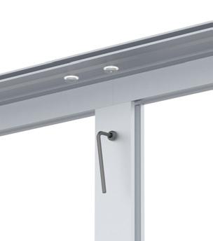
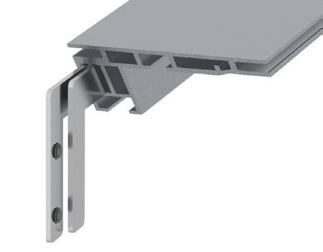
4 Page 4 - Mounting WALL MOUNT: Drill mounting holes in the frame as needed, to align with the EXISTING WALL STUDS. Using an X-acto blade or hole puncher, puncture or cut small holes into the white backing graphic to match the holes just drilled in the frame, then mount to the wall (Mounting screws and anchors not provided - ensure the appropriate type for your wall). HANG: the frame using the pre-mounted eyebolts, after installing graphic (see next page for graphic installation). CAUTION: Always ensure the frame is secured strongly without risk of falling before completing the installation. Wall Mount Holes are drilled by customer at time of installation. Screw Add hole before mounting to wall White Backing Graphic Page 4 of 6


5 Page 5 - Install the Graphic Plug frame into wall outlet. To install the graphic, take the corner with the pull tag on it and press about 6-0 of silicone into the frame channel corner A. Repeat for the opposite corner B. Repeat for the next corner C. Lastly, repeat for the final corner D. 3. After all corners are pressed in, press the silicone into the frame channel at the mid-points on all four sides. 4. Press silicone into frame evenly between the corner and midpoints. This prevents the graphic from bunching up or stretching too much and will ensure a smooth and tight fit. 5. To remove the graphic from the frame, simply pull up on the pull tag. NOTE: Model shown below may differ from your model, but assembly instructions remain the same. B 3. D C A pull tag Page 5 of 6


6 Page 6 - Repair Instructions - Light Replacement: Unplug unit from wall. Remove thumb screws from light strip. 3. Unplug the light strip male/female connectors, then remove the light strip. 4. Refasten the new light strip with the thumb screws, but do not tighten completely. 5. Reconnect the new light strip to the adjacent connections. 6. Tighten the thumb screws to secure the position. 7. Plug in the unit. 3a. ELECTRICAL NOTE: This sign is intended to be installed in accordance with the requirements of Article 600 of the National Electrical Code and/ or other applicable codes. This includes proper grounding and bonding of the sign. 3. Lift out after disconnected 3a. 6. 3b Fastener Nut is in the channel Page 6 of 6
Installation Instructions
 Installation Instructions Optima LED 8 Double-Sided StretchLite Perimeter Lit Graphic Display Line Voltage Connector Optima LED DS5 (Double-sided StretchLite Graphic Display) with Graphics Corner Bracket
Mount to the Wall INSTALLATION MANUAL
 Mount to the Wall 15 Locate the Wooden Studs This step applies to wooden stud wall installation only. Determine and mark the exact locations of two stud centers on the wall. Wooden studs should be spaced
Cosmopolitan Grand Hardware
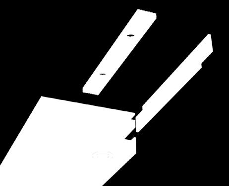
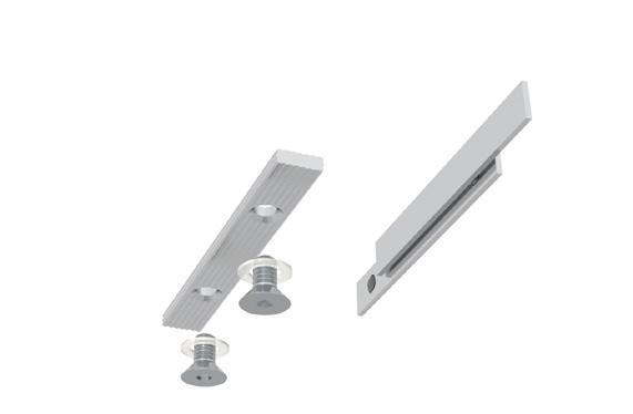
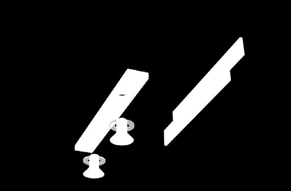
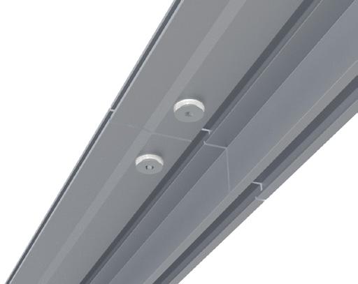
 STEP BY STEP INSTALLATION INSTRUCTIONS Cosmopolitan Grand Hardware Wall Mount Single Corner Rod Set Everything You Need Table of Contents Step 1 - Getting Started...3 Overview - Wall Mount Single Corner
Cosmopolitan Grand Hardware
 STEP BY STEP INSTALLATION INSTRUCTIONS Cosmopolitan Grand Hardware Wall Mount Single Rod Set Everything You Need Table of Contents Step 1 - Getting Started...3 Overview - Wall Mount Single Rod Set...4
Everything. You Need. GeoMod Hardware. Step 1 Parts & Tools. Wall Mount. Brackets & Rod Chart. Care & Cleaning. A Smooth Set-Up.
 Step 1 Parts & Tools Brackets & Rod Chart Installation Instructions QTY QTY WIDTH 1 2 24" 48" SCREWS (3 PER ) 1 2 481/8" 72" 1 3 721/8" 96" 2 4 *961/8" 108" 2 4 *1081/8" 144" 2 5 *1441/8" 192" GeoMod Hardware
Everything SINGLE BRACKET
 Parts & Tools Brackets & Rod Chart Installation Instructions QTY QTY WIDTH 1 2 24" 48" SCREWS (3 PER ) 1 2 481/8" 72" 1 3 721/8" 96" 2 4 *961/8" 108" 2 4 *1081/8" 144" *Note: Width determines if rod comes
ALUMINUM AIR TRIM INSTALLATION INTRODUCTION
 ALUMINUM AIR TRIM INSTALLATION INTRODUCTION KEISER CORPORATION has always taken pride in designing and engineering the highest quality equipment on the market. This means that you will receive years of
FIXED PANEL SLIDER QCI5241
 INSTALLATION INSTRUCTIONS FIXED PANEL SLIDER QCI5241 FRAMELESS PANEL / DOOR / PANEL FRAMELESS DOOR / PANEL QCI5241 REV. 0 Page 1 Certified 06/16/2016 Parts List *Quantities may vary QCI5241 REV. 0 Page
Therma-Tru Door Gallery Setup Instructions Swing Unit with Hardware Kit - Hardware Part # MADGSWU15 (Swing Unit) Part # MADGHKSU10 (Hardware Kit)
 Part # MADGHKSU10 (Hardware Kit)") Swing Unit with Hardware Kit - Hardware Tools Included: 4mm Allen Wrench, 6mm Allen Wrench, 8mm T-Handle Allen Wrench (1) 3/4" Drill Bit, (1) 7/32" Drill Bit and Hole Template Guide Tools Required: Phillips
Swing Unit with Hardware Kit - Hardware Tools Included: 4mm Allen Wrench, 6mm Allen Wrench, 8mm T-Handle Allen Wrench (1) 3/4" Drill Bit, (1) 7/32" Drill Bit and Hole Template Guide Tools Required: Phillips
6MM ALLEN KEY FOR ROOF CLIPS PHILLIPS HEAD BIT FOR SCREWS FOR DOOR FRAME SPIRIT/LASER LEVEL TO LEVEL THE UNIT
 1 TOOLS REQUIRED: MOVING CART/DOLLY FOR TRANSPORTING PANELS, ROOF, AND POSTS TWO 9 FT. STEP LADDERS FOR INSTALLING ROOF & PANELS MINI REVERSIBLE RATCHET 1/4 DRIVE FOR CORNER SCREWS ON TOP TRAVERSE BEAMS
Insolroll Clutch Operated Shades Installation Instructions Installation Instructions
 All clutch operated shades are shipped fully assembled and ready for installation. Mounting screws are not provided. Screws for chain guide installation to meet the child safety standards are provided.
INS A KSR INSTALLATION INSTRUCTIONS STANDARD PROCEDURE. 1. Verify Curb Installation Required Installation Tools...
 INS-88.300-0A KSR INSTALLATION INSTRUCTIONS STANDARD PROCEDURE 1. Verify Curb Installation... 2 2. Required Installation Tools... 2 3. Unpacking the KSR... 3 4. Attach KSR Bottom Rail to Curb... 5 5. Attach
ROMAN AND. Roller Lift System Continuous Cord Loop GETTING STARTED BRACKET INFORMATION INSIDE MOUNT. A few simple tools are required:
 ROMAN AND WOVEN WOOD SHADES Roller Lift System Continuous Cord Loop GETTING STARTED BRACKET INFORMATION A few simple tools are required: The brackets you received with your product are REQUIRED for proper
Office Partitions WARNING. Assembly Instructions. Customer Service A S S E M B LY HARDWARE H1 H2 H3 H4 H5 H8 H9 H10 H11 H12
 Customer Service 1-800-645-2986 Assembly Instructions WARNING In order to prevent structural failure, instability, t i p - o v e r, and/or serious injury, please follow i n s t ructions care f u l l y.
TRUE TECHNICAL SERVICE MANUAL - ALL MODELS. DOORS/DRAWERS/LIDS
 DOORS/DRAWERS/LIDS 55 56 NOTES DOORS/DRAWERS/LIDS Swing s 73 74 NOTES INSTALLATION OF A GDM-SWING DOOR Phillips Head Screwdriver (2) - 1/8" Drift Punches (forged) Top Bracket NOTE: It may be necessary
LIGHT FIXTURES MUST BE COMPLETELY INSTALLED PRIOR TO CEILING CONSTRUCTION
 CAUTION: BEFORE BEGINNING INSTALLATION REVIEW LAYOUT DRAWINGS, AND SHIPMENT. MAKE SURE ALL LIGHT S AND MATERIALS ARE ON SITE AND READILY ACCESSIBLE. IF ANY ICON MATERIALS ARE MISSING, CONTACT ICON INTERNATIONAL
Deck Mount Installation with Bench
 Deck Mount Installation with Bench 1. Mark track with square. 2. Cut tracks with saw. 3. Drill ¼ hole (if needed.) 4. Countersink track. 5. Countersink all track 6. File all track ends. ends. 7. Lay out
Tradewinds Amplify Display System Instructions
 Table of Contents Packing & Unpacking... Standard Kits... Component Identification... Primary Components Vertical Pole Top... Vertical Pole Bottom... Horizontal... Cross/Hanging Bar... Amplify Shelf Package
INS A KSCR INSTALLATION INSTRUCTIONS STANDARD PROCEDURE. 1. Unpacking the KSCR Splicing the KSCR (If Required)...
...") INS-88.500-0A KSCR INSTALLATION INSTRUCTIONS STANDARD PROCEDURE 1. Unpacking the KSCR... 2 2. Splicing the KSCR (If Required)... 4 3. Assemble Curb and Rail Corners... 5 4. Install Cross Bracing (If Required)...
INS-88.500-0A KSCR INSTALLATION INSTRUCTIONS STANDARD PROCEDURE 1. Unpacking the KSCR... 2 2. Splicing the KSCR (If Required)... 4 3. Assemble Curb and Rail Corners... 5 4. Install Cross Bracing (If Required)...
Austin Standing Seam Awning Assembly and Installation Instructions. Assembly Instructions
 Austin Standing Seam Awning Assembly and Installation Instructions Be sure to use safety glasses when assembling and installing the awning. Some metal parts may have sharp edges. Use work gloves to handle
Assembly Instructions
 Selling Station Assembly Instructions View from above without top A B C D Rounded finished corners on A & D Square unfinished 3-sides on B & C Selling Station Components (2) 2' x 6' Side s Have a channel
Austin Standing Seam Awning with Overhead Braces Assembly and Installation Instructions. Assembly Instructions
 Austin Standing Seam Awning with Overhead Braces Assembly and Installation Instructions Be sure to use safety glasses when assembling and installing the awning. Some metal parts may have sharp edges. Use
13MM FLAT WRENCH FOR LEVELING THE GLIDES OF STRUCTURE 6MM ALLEN KEY FOR ROOF CLIPS PHILLIPS HEAD BIT FOR SCREWS FOR DOOR FRAME
 1 TOOLS REQUIRED: MOVING CART/DOLLY FOR TRANSPORTING PANELS, ROOF, AND POSTS TWO 9 FT. STEP LADDERS FOR INSTALLING ROOF & PANELS REVERSIBLE RATCHET 1/4 DRIVE FOR CORNER SCREWS ON TOP TRAVERSE BEAMS ALTERNATIVE
a.k.a. casegoods instructions
 a.k.a. casegoods instructions a a.k.a. workwall installation IMPORTANT NOTES Failure to install product according to installation instruction will result in loss of warranty. Tools required for assembly
3 D Printer Enclosure Assembly Instructions
 3 D Printer Enclosure Assembly Instructions Tools Required: 2.5 mm Allen wrench (included) Phillips screwdriver Adjustable Wrench Parts Included: Plexiglas Back with fan and filters installed (29.5 x 35.5
TrendWall Floor-To-Ceiling Panels Installation Instruction
 TrendWall Floor-To-Ceiling Panels Installation Instruction TrendWall Components Covered by this Instruction: Crown (and accessories) Floor Plate Solid Panel Filler Panel Wall Channel Door Section Pilaster
Panel & Shelf Identification
 4 to 8 Aromatic Cedar Closet Model # 801 1 PLEASE READ INSTALLATION INSTRUCTIONS BEFORE ASSEMBLING Rev. C IF YOU ARE MISSING PARTS OR HAVE QUESTIONS PLEASE CONTACT: customerservice@cedargreen.net Tools
MasterFlow Green Machine Dual Powered Roof Vent
 MasterFlow Green Machine Dual Powered Roof Vent Application Instructions Updated: 2/10 Quality You Can Trust Since 1886... From North America s Largest Roofing Manufacturer Safety Considerations and Warnings
WOVEN WOOD SHADES Corded, Continuous Cord Loop or Upended
 WOVEN WOOD SHADES Corded, Continuous Cord Loop or Upended GETTING STARTED HARDWARE INFORMATION A few simple tools are required: The hardware you received with your product are REQUIRED for proper installation.
Wall mounting bracket
 Install Manual Wall mounting bracket Please read this manual carefully before operating your set and retain it for future reference. OSW200 P/NO : MFL63640578 (1502-REV01) www.lg.com COMPONENT Install
Installation Instructions: VIBRATION ISOLATION RAIL (CPR)
") Table of Contents: 1. Quick Installation Instructions 2. Required Tools 3. Supplied Parts 4. Step by Step Instructions 5. Leveling Instructions Spring Color Key (1 and 2 ) Blue 30 lb Green - 60 lb Red
Table of Contents: 1. Quick Installation Instructions 2. Required Tools 3. Supplied Parts 4. Step by Step Instructions 5. Leveling Instructions Spring Color Key (1 and 2 ) Blue 30 lb Green - 60 lb Red
Repair Instructions. Replacing and Installing a Sweep Motor. Elite Models that Apply: Phenom 1 & 2. Step Description Tools Picture
 Elite Models that Apply: Phenom 1 & 2 Step Description Tools Picture Disconnecting The Phenom Hopper Unit and Base Unit. 1 Step 1.) Unscrew the 4 wing screws (D) and washers (C) from the bottom of the
Enlighten. Enlighten. exponorm. Legend. Legend. (1) Left Mitre Edge Extrusion with pre-installed threads for baseplate attachment
 Left Mitre Edge Extrusion with pre-installed threads for baseplate attachment") exponorm. LED BackWall Montage - Anleitung Legend (8) Cross Seam Stabilizer (CSS) (2) Crescent Baseplate (1) Right Mitre Edge Extrusion with pre-installed threads for baseplate attachment (1) Left Mitre
exponorm. LED BackWall Montage - Anleitung Legend (8) Cross Seam Stabilizer (CSS) (2) Crescent Baseplate (1) Right Mitre Edge Extrusion with pre-installed threads for baseplate attachment (1) Left Mitre
TIP FOR GETTING STARTED
 Tip for getting started TIP FOR GETTING STARTED Be careful not to drill into any electrical wires, ductwork, plumbing or other damagable components. If you have any questions on the locations of these
Due to possible damage in shipping, the vertical stop assembly has been removed from this machine.
 Due to possible damage in shipping, the vertical stop assembly has been removed from this machine. To assemble, insert the threaded rod through the shroud opening in the top of the machine. Start the four
AM8 Printer A metal frame for your Anet A8 By Pheneeny v1.0 April 20, 2017
 AM8 Printer A metal frame for your Anet A8 By Pheneeny v1.0 April 20, 2017 Please read this entire document before printing parts or building this frame Disclaimer: This guide is for informational purposes
Installation Instructions Road King Classic Saddlebag Bezels
 Installation Instructions Road King Classic Saddlebag Bezels Thank you for your purchase of Bagger Audio Road King Classic Saddlebag Bezels for your Harley-Davidson motorcycle. We have carefully engineered
LEGENDS RETRACTABLE DOOR SCREENS
 LEGENDS RETRACTABLE DOOR SCREENS MAGNETIC LATCHING DESIGN SYSTEM 42 I N S T A L L A T I O N I N S T R U C T I O N S 1 MOUNTING OPTIONS Recess : Mount the Screen Cassette using Recess Mounting Clips Recess
BLADE N BULLET BLIND Cabela s Item Number:
 BLADE N BULLET BLIND Cabela s Item Number: 466353 Visit cabelas.com or call 1-800-237-4444 for assistance. TABLE OF CONTENTS 2 3 4-13 Table of Contents Package Contents Instructions for Use Visit cabelas.com
Q-Zone Hoop-Frame. Assembly Instructions. Copyright July 11, 2018 Grace Company (Reproduction Prohibited) Version 1.8
 Version 1.8") Q-Zone Hoop-Frame Assembly Instructions Copyright July 11, 2018 Grace Company (Reproduction Prohibited) Version 1.8 Table of Contents Table of Contents... i Warranty... ii Parts List Box 1...iii Box 2...
Q-Zone Hoop-Frame Assembly Instructions Copyright July 11, 2018 Grace Company (Reproduction Prohibited) Version 1.8 Table of Contents Table of Contents... i Warranty... ii Parts List Box 1...iii Box 2...
INSTALLATION: D1-NOTCH DRYWALL TRIM FLANGE
 T F W 604.549.979 604.549.9555 fluxwerx.com INSTALLATION: D1-NOTCH DRYWALL TRIM FLANGE fixture housing endcap kit optic kit join kit notch 2 cross section notch 4 cross section 4 4" 4-11/2" 4 /8 (111)
Continuum Frame Assembly Instructions
 Continuum Frame Assembly Instructions Copyright January 1, 2017 Jim M. Bagley, GraceWood, Inc (Reproduction Prohibited) Version 2.2 Table of Contents Continuum Frame Table of Contents... i Warranty...ii
Instruction page index: Installation Instructions for Bosca Models BOS-XX-C-XX, & BOS-XX-S-XX. Page 1 of 5
 Installation Instructions for Bosca Models BOS-XX-C-XX, & BOS-XX-S-XX Page of 5 BOSCA clip-in mount or BOSCA magnetic BOSCA -in mount Instruction page index: Clip-in installation Screw-in installation
Rugged Ridge 2 Receiver Hitch Kit (J21068)
") Rugged Ridge 2 Receiver Hitch Kit (J21068) Installation Time: 1-2 Hours Tools Required: ¾ Open End Wrench 18 mm Socket ¼ drive Pliers/Needle nose pliers/channel locks, etc. Torque wrench Phillips head
Rugged Ridge 2 Receiver Hitch Kit (J21068) Installation Time: 1-2 Hours Tools Required: ¾ Open End Wrench 18 mm Socket ¼ drive Pliers/Needle nose pliers/channel locks, etc. Torque wrench Phillips head
Desk/Wall-Mount Rack
 Desk/Wall-Mount Rack Patent(s) Pending Installation Instructions Post P/N: 119-1752 119-1781 119-1782 119-4014 Frame P/N: 119-1591 119-1754 119-1755 Kit Contents (2) Frames (4) Posts Assembly Hardware
Frameless Inline Door With Return QCI5263
 INSTALLATION INSTRUCTIONS Frameless Inline Door With Return QCI5263 WALL MOUNT HINGES FRAMELESS DOOR / PANEL / RETURN PANEL QCI5263 REV. 0 Page 1 Certified 06/17/2016 Parts List with wall mount hinges
6' Wide Premium Greenhouse Benches
 6' Wide Premium Greenhouse Benches Premium Greenhouse Bench with Stationary Top 2015 FarmTek All Rights Reserved. Reproduction is prohibited without permission. STK# DIMENSIONS 112416S6X08 6' W x 3' H
THANK YOU FOR PURCHASING FROM HERITAGE PATIOS
 Installation Guide THANK YOU FOR PURCHASING FROM HERITAGE PATIOS Your purchase is engineered by nearly a half century of commercial and residential product design proudly manufactured in the USA from responsibly
Hybrid Pro Counter 01
 Hybrid Pro Counter 01 HPC-01 All Hybrid Pro Modular counters feature accessible storage and locking doors. Purchased magnet applied graphic panel allows for your messaging and branding. features and benefits:
compile system INSTALLATION GUIDE Updated January 2019
 INSTALLATION GUIDE Updated January 09 compile system Table of Contents Panels 0 Quick Connect Clips 0 Lock Clips 0 Panel Trims 0 Privacy Glass 0 Post Base Covers 04 Electrical 04 Power Distribution Harness
SAFETY THIS PRODUCT IS FOR OFFROAD USE ONLY. ALL LIABILITY FOR INSTALLATION AND USE RESTS WITH THE OWNER.
 SAFETY Your safety and the safety of others is very important. In order to help you make informed decisions about safety, we have provided installation instructions and other information. These instructions
Important Safety Instructions
 Basis Track Installation Guide Important Safety Instructions Lighting systems from Translite Sonoma are supplied as complete systems. Use only factory-supplied parts to preserve the validity of the UL
Assembly Instructions
 InTandem Table System November 20 InTandem Table System - Worksurface #4 x/" 4 wood screw power beam Tools Provided T-0 Extended Torx Driver T-25 Torx Driver Additional Tools Required Soft protective
Gazebo ASSEMBLY INSTRUCTIONS. Urban
 Urban Gazebo ASSEMBLY INSTRUCTIONS Urban's Installation Instructions conceptualize the assembly of Urban's products. Urban does not warrant the accuracy or sufficiency of any advice or recommendations
WALL MOUNT LOCKER ASSEMBLY. 208 Chestnut St, Reading, PA (610)
") WALL MOUNT LOCKER ASSEMBLY 208 Chestnut St, Reading, PA 19602 (610)376-2666 Locker Assembly Wall Mount: locker Installation Introduction: Before beginning, check to ensure the floor is level, and the wall
WALL MOUNT LOCKER ASSEMBLY 208 Chestnut St, Reading, PA 19602 (610)376-2666 Locker Assembly Wall Mount: locker Installation Introduction: Before beginning, check to ensure the floor is level, and the wall
Setup. The Faraday Cage is available in two types of configurations. Cage for mounting to a full perimeter enclosure on series tables.
 Faraday CageSetup, 2017 Setup The Faraday Cage is available in two types of configurations. Cage for mounting to a full perimeter enclosure on 63-500 series tables. Cage with a base plate for use on a
Monaco Installation Guide - Surface Profiles
 v1 Page 1 Thank you for purchasing this Monaco shower screen. Please study these instructions carefully before assembly and installation and check all supplied parts immediately upon receipt. These instructions
Face Mount to Through-the-Post Mount
 Face Mount to Through-the- Mount Cable Runs through Two Corners When going around two corners, it s necessary to tension the cable from both ends as shown in Deck 4. Use the 672 series The tensioning devices
Lunette Series. Home Theater Curved Fixed Frame Projection Screen. User s Guide. Important Safety and Warning Precautions
 Lunette Series Home Theater Curved Fixed Frame Projection Screen User s Guide Important Safety and Warning Precautions Please follow these instructions carefully to ensure proper maintenance and safety
Fixed Wall Arm. Installation Guide. Part number Rev E 2012 PolyVision Corporation All rights reserved
 Fixed Wall Arm Installation Guide Part number 2002003-001 Rev E 2012 PolyVision Corporation All rights reserved Table of contents Important Safety Instructions... 3 Overview... 4 Important considerations...
HP-2 Recessed Wall Wash Flush Diffuser Tech Zone 4" Starter/Independent Installation Instructions
 HP-2 Recessed Wall Wash Flush Tech Zone /Independent Scan QR code for helpful video(s) Step 1 Step 2 Tech Zone Collection. Center-to-center spacing Wall 0-10V Dimming.0.0.0 Tech Zone (C1) Tech Zone (C2)
Mounting Instructions Item No.: xxx
 Mounting Instructions Item No.: 271.92.xxx Wall-Beds 1 General Notes For vertical folding beds Successful and safe installation of Bed-Lift and construction of casework requires a professional skill level
TOOLS REQUIRED: HARDWARE INCLUDED: 13MM FLAT WRENCH FOR LEVELING THE STRUCTURE RATCHET WITH 5MM HEX BIT FOR CORNER SCREWS ON TOP TRAVERSE BEAMS
 1 TOOLS REQUIRED: RATCHET WITH 5MM HEX BIT FOR CORNER SCREWS ON TOP TRAVERSE BEAMS 13MM FLAT WRENCH FOR LEVELING THE STRUCTURE RUBBER MALLET FOR INSERTING PANELS 8MM HEX BIT WITH EXTENSION FOR HEX BOLT
Stair Mounting Kit. Installing safety gates in modern homes can be very challenging, especially for stairs.
 Stair Mounting Kit Installation Guide Installing safety gates in modern homes can be very challenging, especially for stairs. The Stair Mounting Kit will allow you to mount gates to most square and round
Repair Instructions. Replacing a La Z Time Mechanism Side Subassembly. Remove the Back(s): Remove the Mechanism Assembly: CAUTION.
: Remove the Mechanism Assembly: CAUTION.") Replacing a La Z Time Mechanism Side Subassembly Tools Required: Slotted Screwdriver Power Driver 8" Driver Extension Ruler Note: Extension springs are not typically used on non-chaise standard width styles,
Replacing a La Z Time Mechanism Side Subassembly Tools Required: Slotted Screwdriver Power Driver 8" Driver Extension Ruler Note: Extension springs are not typically used on non-chaise standard width styles,
Installation Instructions
 by Plato Woodwork Installation Instructions Plato Woodwork, Inc. 200 Third Street SW P.O. Box 98 Plato, MN 55370 www.platowoodwork.com 800.328.5924 SECTION GUIDE GETTING STARTED PAGE # Installation Methods...
User Instructions Multiline Otter Scoreboard Caddy Assembly
 List of parts: User Instructions Multiline Otter Scoreboard Caddy Assembly Single Caddy Double Caddy 1 1 Base assembly with attached wheels 2 4 1 1 2 4 4 8 10 20 12 Uprights (60 or 74 aluminum extrusion)
CABANA / PAVILION ASSEMBLY ALUMINUM FRAME MODELS
 Assembled cabanas are large & heavy. Assemble at place of use. CABANA / PAVILION ASSEMBLY ALUMINUM FRAME MODELS Step 1 CAUTION: To avoid damage to the finish of your Cabana frame, prepare a smooth, non-scratch
Depending on the size you ordered you will have either 5 Foot sections which will build the 10 Foot frame or 6 Foot sections which will build the 12
 XL Quilting Frame 1 Depending on the size you ordered you will have either 5 Foot sections which will build the 10 Foot frame or 6 Foot sections which will build the 12 Foot frame Printed 2 June 2014 Updated
Hawko Zhaga Systems Installation Instructions
 Hawko Zhaga Systems Installation Instructions Contents Wire Suspension Installation 4 Recessed Brackets 6 Fixed Suspension Rods 8 Swivel Suspension Rods 10 Surface Mount Ceiling 12 Surface Mount Wall
Assembly and installation help
 Assembly and installation help A supplement to the directions The Purpose of this tutorial is to expand (not replace) upon the directions that come with the system and to help provide shortcuts, the first
1200 SERIES 2 PANEL DOOR rev.1 DETAILED INSTALLATION INTRUCTIONS
 1200 SERIES 2 PANEL DOOR 10.2013 rev.1 DETAILED INSTALLATION INTRUCTIONS GENERAL: Door elevations shown in these instructions are as viewed from the outside. X denotes the active or moving panel(s). O
6' Wide Premium Greenhouse Benches
 6' Wide Premium Greenhouse Benches Premium Greenhouse Bench with Rolling Top 2015 FarmTek All Rights Reserved. Reproduction is prohibited without permission. STK# DIMENSIONS 112416R6X08 6' W x 3' H x 8'
Solar & Roller Shades
 STEP BY STEP INSTALLATION INSTRUCTIONS Solar & Roller Shades Cordless Control with Mounting Bar or Cordless Control with Cassette Table of Contents Step 1 - Getting Started.... 3 Everything You Need A
STEP BY STEP INSTALLATION INSTRUCTIONS. Pleated Shades. Easy Lift Cordless
 STEP BY STEP INSTALLATION INSTRUCTIONS Pleated Shades Easy Lift Cordless Everything You Need Table of Contents Step 1 - Getting Started................................... 3 Overview - Cordless Control...................................
GARAGE DOOR WITH TORSION SPRING
 GARAGE DOOR WITH TORSION SPRING DIMENSIONS 9 WIDTH X 7 HEIGHT (2.74m x 2.13m) IMPORTANT SAFETY INSTRUCTIONS WARNING: Read all instructions and warnings before use. Failure to follow all instructions may
 Menu Board Tilt or Fixed Mount Installation Instructions MDS1T-200, MDS1T-300, MDS1T-400 MDS2T-200, MDS2T-300, MDS2T-400 MDS3T-200, MDS3T-300, MDS3T-400 MDS4T-200, MDS4T-300, MDS4T-400 MDS5T-200, MDS5T-300,
45 CUTTING HEAD TILE SAW-BLADE ALIGNMENT PROCEDURE
 The of the MK-770 may become misaligned with the Cutting Head of the Tile Saw over time. Should misalignment occur, perform the following steps to realign the Tile Saw. NOTE: If alignment problems are
Assembly Instructions
 Unite Panel System Hinge Door July 2016 #12 x / slotted hex washer head bolt Figure 1 threshold bracket frame Detail F threshold bracket threshold bracket (installed) #12 x / slotted hex washer head bolt
Video Wall Installation Instructions 2W X 3H, 3W X 3H
 Video Wall Installation Instructions 2W X 3H, 3W X 3H www.microndisplaysolutions.com Table of Contents Important Safety Instructions... 3 Configuration... 4 Package Contents, included and optional items...
LARGE FLAT PANEL DISPLAY STATIC MOUNT PST 2000 Series
 INSTALLATION INSTRUCTIONS LARGE FLAT PANEL DISPLAY STATIC MOUNT The PST static wall mount accommodates large flat screens weighing up to 200 lbs (90.72kg). The teardrop holes in the mount allow for quick
STEP BY STEP INSTALLATION INSTRUCTIONS. Sheer Shadings. Cordless Control
 STEP BY STEP INSTALLATION INSTRUCTIONS Sheer Shadings Cordless Control Everything You Need A Smooth Set-Up We want you to love your new window coverings and that includes having a smooth installation experience.
HQ Precision-Glide Track Upgrade 2 Extension Kit for HQ Studio Frame Part# QF09750
 HQ Precision-Glide Track Upgrade 2 Extension Kit for HQ Studio Frame Part# QF09750 Important Note: Upgrading the track system on the HQ Studio Frame requires the use of this 2 Extension Kit (Part #QF09750),
MISCELLANEOUS CABINET REPAIRS
 MISCELLANEOUS CABINET REPAIRS 167 168 NOTES MISCELLANEOUS CABINET REPAIRS Cabinet Panel Repairs 175 SIDE PANEL REPLACEMENT - GDM SERIES INSTALLATION INSTRUCTIONS Tools Required 1/8" drill Rivet Tool Silicone
Installation Instructions for TruLine 1A Center Feed Power Channel Connector
 IMPORTANT INFORMATION - This instruction must be used concurrently with other TruLine A BIY installation instructions. - This product is wall or ceiling mount. - This instruction shows a typical installation.
Solar & Roller Shades
 STEP BY STEP INSTALLATION INSTRUCTIONS Solar & Roller Shades Cordless Control with Mounting Bar or Cordless Control with Cassette Everything You Need A Smooth Set-Up We want you to love your new window
IDR assembly instructions:
 IDR assembly instructions: Required Tools: 2 X 12mm Open End Wrench 14mm open end wrench #2 Phillips Head Screw Driver (Drill with adjustable torque clutch recommended) 8mm nut driver (Supplied in IDR-AK)
INSTALLATION AND CARE INSTRUCTIONS
 INSTALLATION AND CARE INSTRUCTIONS Skylight Manually Operated Honeycomb Shades 20 C8-10-1806 2/15 1 INTRODUCTION Thank you for purchasing our product. Your new shade has been custom built for you from
Thank you for your order
 Installation Guide Thank you for your order Ph: 09-9133110 Fax: 09-9133113 5 Smales Road. East Tamaki, Manukau PO Box 58031 Greenmount, Manukau 2013 AUCKLAND // WELLINGTON // CHRISTCHURCH www.bathroomdirect.co.nz
Gold Crown POCKET BILLIARD TABLE INSTALLATION MANUAL. SERVICE DEPARTMENT P.O. BOX 68 BRISTOL, WI 53104
 Gold Crown TM V POCKET BILLIARD TABLE INSTALLATION MANUAL www.brunswickbilliards.com SERVICE DEPARTMENT P.O. BOX 68 BRISTOL, WI 53104 51-905708-000 OCTOBER 2007 NOTE: Please use the instructions in this
How to Install Custom Real Wood and Faux Wood Blinds
 Before you begin your installation: READ ALL INSTALLATION INSTRUCTIONS! Make sure that you have all tools and hardware needed for installation. Check the installation surface (wall, ceiling, or window
Roomba 500 Series Servicing and Repair Guide. Chapter 3: How to Open Up Roomba
 Roomba 500 Series Servicing and Repair Guide Chapter 3: How to Open Up Roomba 1 This repair guide explains how to perform general disassembly on the Roomba 500 series robot vacuum. It is suggested to consult
Frameless Inline Door QCI5254
 INSTALLATION INSTRUCTIONS Frameless Inline Door QCI5254 FRAMELESS DOOR / PANEL QCI5254 REV. 0 Page 1 Cer fied 06/16/2016 Parts List with wall mount hinges *Quanes may vary QCI5254 REV. 0 Page 2 Cer fied
Riverside. Windward Bay EntertaInment Wall System Assembly Instructions. Made In Viet Nam. Right Pier. Bridge & Back Panel.
 EntertaInment Wall System Page 1 of 12 Product No. 42840 42848 42849 42843 Product Description Console Left Pier Right Pier Bridge & Back Panel Right Pier Bridge & Back Panel Left Pier 63" Inch Ent. Console
Motorized or Crank Operated Fortress Zipper Track Shade with Housing and Side Track Installation Instructions
 Motorized or Crank Operated Fortress Zipper Track Shade with Housing and Side Track Installation Instructions Tools Needed Drill 3/8 Metal Drill Bit ¼ Masonry Drill Bit Measuring Tape Pencil 4 Level Phillips
Copyright Black Box Corporation. All rights reserved Park Drive Lawrence, PA Fax
 Copyright 2003. Black Box Corporation. All rights reserved. 1000 Park Drive Lawrence, PA 15055-1018 724-746-5500 Fax 724-746-0746 JULY 2003 RM3010A RM315-R2 RM323-R2 RM329 RM451 RM457 RM3020A RM316 RM324-R2
Simply lift up on the flexible cover to remove it from the radiator support panel and factory grille, exposing the upper mounting hardware.
 2 Simply lift up on the flexible cover to remove it from the radiator support panel and factory grille, exposing the upper mounting hardware. Apply masking tape to the top of the bumper cover underneath
Linear Drain Installation Guide
 Linear Drain Installation Guide Carefully review all installation options and instructions before proceeding. bronte LINEAR DRAIN INCLUDES: Base and Strainer Grate Kits ordered separately. Both are required
VACUSEAL MODEL 200. HOT TUB PRODUCTS 233 Carrington Road Bethany CT
 VACUSEAL MODEL 200 J G F G H L HOT TUB PRODUCTS 233 Carrington Road Bethany CT 06524 860-469-2580 www.vacusealcoverlift.com www.hottubproducts.com Made in USA H K E D C I A P B 10 9 8 7 6 5 4 3 2 1 0 SPAS
Exponents Bench Cushion
 Exponents Bench Cushion Power Drill #2 Phillips Bit Bit Holder Page 1 of 2 939500640 Rev A 1. Place cushion on top of the bench, so the black Coalesse tag is in the right rear corner of the bench. 2. From