EDP# Model 26 MAINTENANCE INSTRUCTIONS AND PARTS LIST. Better By . :;]- ~, Iiii. McMINNVILLE, TENNESSEE D AC
|
|
|
- Ashley Cory Hardy
- 5 years ago
- Views:
Transcription


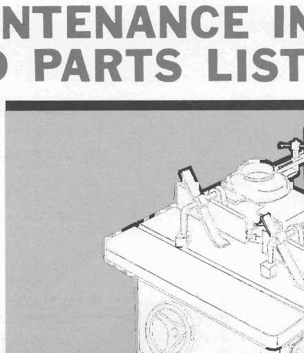


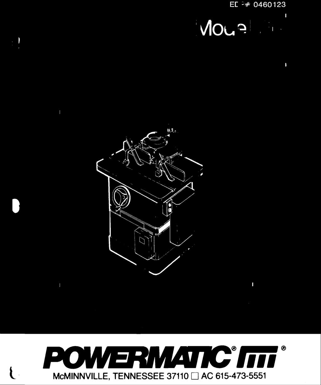
1 EDP# 040 Model MAINTENANCE INSTRUCTIONS AND PARTS LIST Better By :;]- ~, Iiii McMINNVILLE, TENNESSEE 70 D AC

 4 90 SCREW, SET 800 HANDLE 4 7407 SCR., FILLISTER HD.")


 7 50 SCR., SOC.")
 74004 SCR., soc. SET, CUP PT.")

 0 44000 LATCH, No. -- 0 004 DOOR ASSY. (WE LDMENT) 8900 I SCALE ASSY.")
 480 PLATE,MTG.")

2 PARTS LIST: Stand & Table ITEM PART ITEM PART NO. NO. DESCRIPTION IOTY. NO. NO. DESCRIPTION OTY FENCE ASSY., SHAPER (ITEMS BRACKET, SWITCH MTG. THRU 9) PLATE, SHAPER TABLE SCREW, LOCK ASSY. (ITEMS PIN, STARTER THRU ) 4 90 SCREW, SET 800 HANDLE SCR., FILLISTER HD., 9500 SCREW, LOCK /4-0 X " (PLATED) 400 KNOB, HANDLE INSERT, RING NUT, HEX JAM, 5/ CAP WASHER, FLAT, 5/" ZINC 8805 KIT PLATE, SHAPER PLATED 4 (ITEMS 4 THRU 5 ) 0074 BRACKET, MOUNTING, FENCE RIVET, SOUTHCO ALUM., SHAPER, R.H. 5/ X /4" LG FENCE, BOARD 47 5 I.D. PLATE, POWERMATIC SCR., FLATHD. MACH., 5/ I.D. PLATE, SERIAL & MODEL 8 X /" (ZINC PLATED 4 NUMBER WASHER, BEVEL, LOCK SCR SCR., DRIVE, No.4 X /" 0 88 SPACER, /8 X 5/8 X.0" 4 (NICKEL PLATED) 7 50 SCR., SOC. SET, CUP PT., LABEL, CAUTION SPINDLE 5/-8 X /8" SHIPPED DRY (NOT SHOWN) 7505 SCR., SOC. HD. CAP, 5/ PLATE, SAFETY (NOT X /4" SHOWN) SCR., soc. SET, CUP PT., /4-0 X /4" KNOB, ADJUSTING SCREW SCREW, ADJUSTING 0405 BRACKET, FENCE GUARD, SHAPER BODY 8 70 SCR., SO(. HD. CAP, /8- X " BRACKET, MOUNTING, FENCE SHAPER, L.H. 00 DOOR ASSY. (ITEMS 0 & ) LATCH, No DOOR ASSY. (WE LDMENT) 8900 I SCALE ASSY., HEIGHT ADJ. (ITEMS & ) 480 PLATE,MTG., HEIGHT ADJ. 840 SCALE, PLATE 7004 HANDWHEEL ASSEMBLY (ITEMS 4 THRU 7) PIN, GROOVE, /4 X " LG HANDLE 705 HANDWHEEL, " DIA SCR., soc. STE, 5/-8 X /8' SCR., FLAT HD., /4-0 X /4" NUT, HEX, / WASHER, LOCK, /4" 8008 EXTENSION, 8" TABLE 800 WASHER, LOCK, /8" 70 SCR., HEX HD., /8- X " 4 80 WASHER, FLAT, /8" STAND ASSY., SHAPER (WELDMENT) TABLE, SHAPER COVER ASSY., MOTOR (WELDMENT) J SCR., HEX HD., /4-0 X 5/8" (SELF.TAPPING) 8


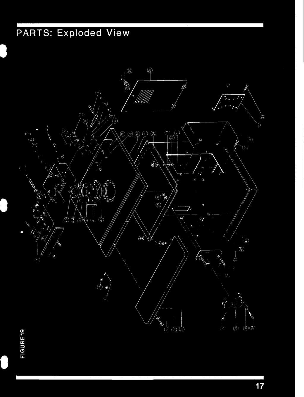
3 PARTS: Exploded View \ \ \ 7
 5/-8 x 5/\" 5800 PINION ASSY., WORM GEAR 4 07707 BELT,7M70 (ITEMS THRU ) 44 7804 SHEAVE, MOTOR, STEP 0944 COLLAR -/8\" BORE (ALT. FOR) 7505 SCR., SOC.")


 00RPM, 00V, 45T FR.")
4 P ARTS LIST: Body Assembly ITEM PART ITEM PART NO. NO. DESCRIPTION IOTY. NO. NO. DESCRIPTION 0TY HEAD ASSY., SLIDE (ITEMS SCR., SOC. SET, CUP PT., THRU ) 5/-8 x 5/" 5800 PINION ASSY., WORM GEAR BELT,7M70 (ITEMS THRU ) SHEAVE, MOTOR, STEP 0944 COLLAR -/8" BORE (ALT. FOR) 7505 SCR., SOC. SET, 5/-8 X /4" 80) 890 WASHER, FLAT, NYLATRON SHEAVE, MOTOR:, STEP, /4" E- 7/8" BORE BUSHING, BRONZE /4 I.D. X SCR., HED HD., //4-0 X /" 7/8 O.D. X /4" BASE, MOTOR BUSHING, ADJ. SHAFT SCR., HEX HD. CAP, / PINION X -/" 9000 SCREW ASSY., HEAD RAISING WASHER, BEVEL (ITEMS 7 THRU 0) WASHER, LOCK, /" SCR., SOC. SET, /4-0 X /4" SCR., HEX WASHER HD., GEAR, HEAD RAISING, SPIRAL 5/-8 X /4" KEY, WOODRUFF No MOTOR, ELEC, lhp, lph, SCREW, ELEVATING 00RPM, 5/0V, 5 FR. TEFC 4409 GIB, HEAD SLIDE 478 MOTOR, ELEC, HP,l PH, NUT, HEX JAM, 5/" 00RPM, 00V 5FR. TEFC SCR., SOC. HD. SET. 5/ MOTOR, ELEC. HP, PH, Xl" 00RPM, 0/40V, 5 FR NUT, HEX-THIN HEIGHT, 5/8 TEFC -, FLEXLOC, FKF MOTOR, ELEC, /HP, PH, WASHER, NYLATRON, 5/8" 00 RPM, 5/0V, 5 FR'I 7500 SPACER, ELEVATING SCREW TEFC SLIDE, HEAD 474 MOTOR, ELEC., -/HP, PH, KEY, MOTOR BASE 00RPM, 00V, 5FR, TEFC 9 08 PIN, SPRING, / X /" 474 MOTOR, ELEC., l l/hp, PH, 0 70 SCR., HEX HD., /8- X /" 00 RPM, 0/40V, 5 FR'I 800 WASHER, LOCK, /8" TEFC 8700 WASHER, ELEVATING SCREW 4770 MOTOR, ELEC., HP, PH, STOP 00RPM, 0/40V, 45T FR. 800 WASHER, LOCK, 5/" 4 TEFC SCR., HEX HD., 5/-8 X /4" MOTOR, ELEC., HP, PH, I BODY, SHAPER 00RPM, 5/0V, 45T FR. 750 SCR., HEX HD., 5/-8 Xl" TEFC 7000 ROD ASSY., POINTER 4777 MOTOR, ELEC., HP, PH, (ITEMS 7 THRU ) 00RPM, 00V, 45T FR NUT, HEX JAM, /8- TEFC 8 80 WASHER, FLAT, /8" BASE, POINTER ROD ROD, POINTER 0400 POINTER 7005 SCR., RD. HD. MACH., - X /4" (ZINC PLATED) SHAFT HEAD LOCK ASSY. (ITEMS THRU 7) 400 KNOB, HANDLE SCR., SOC. SET, CUP PT., 5/-8 X 5/" SHAFT, LOCK 0004 HUB, LOCK SHAFT HANDLE 7004 HANDWHEEL ASSY., (ITEMS 8 THRU 4) PIN, GROOVE, /4 X " LG HANDLE HANDWHEEL, " DIA: SCR., SOC. HD. SET, 5/-8 X /8" 8


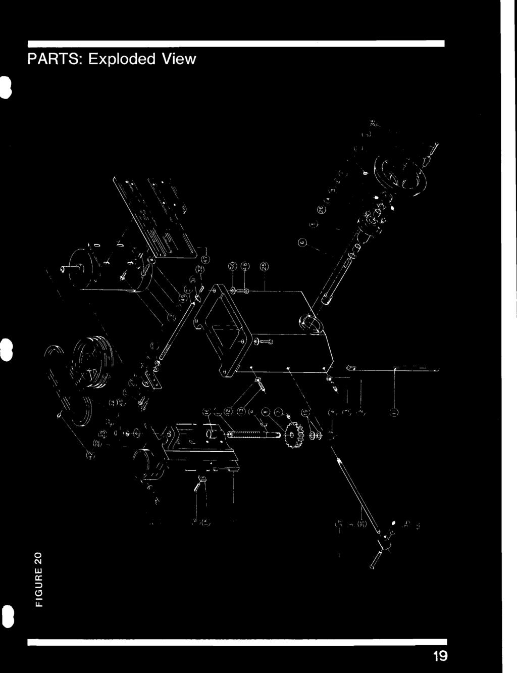
5 P ARTS: Exploded View o N W a: ::J " U. 9


6 /4 INCH SPINDLE ASSEMBLY FIGURE 4 0 /I I././ 7 I I 9 I / /I /' I, I i/ 5 8 EDP ITEN NO PART NO DESCRIPTION Nut, /4" Spindle Lockwasher, /4" Spindle Spacer, Spindle /4 x / Spacer, Spindle /4 x /4 Screw, Button Head Soc. 8- x / Ring, Retainer RSN - 7 Retainer, Bearing Spindle, /4" Solid Key, Square Bearing, 05 - RSTG Truarc External Ring, Retainer IN - 0 Quill Ring, Retainer Sheave, Spindle Washer WD 4, Lock Bearing Steel Plain Nut, Bearing Lock N - 04 QTY. 0


7 INCH SPINDLE ASSEMBLY 4 FIGURE J 4 J / / 9 8 EDP ITEN NO PART NO DESCRIPTION Nut, I" Spindle Lockwasher, I" Spindle Spacer, Spindle x / Spacer, Spindle x /4 Screw, Button Head Soc. 8- x / Ring, Retainer RSN - 7 Retainer, Bearing Spindle, I" Solid Key, Square Bearing, 05 - RSTG Truarc External Ring, Retainer IN - 0 Quill Ring, Retainer Sheave, Spindle Washer, Lock Bearing Steel Plain Nut, Bearing Lock N - 04 QTY.


8 INTERCHANGEABLE SPINDLE ASSEMBLY FIGURE 9 8 f5 (A) /,/ - J ITEH NO. PART NO. DESCRIPTION Straight Shank EDP Taper Shank EDP QTY. SCREW A A A 5 Bottom Head Sea. 8- X / Ring, Retainer RSN - 7 Retainer, Bearing Spindle, Interchangeable straight shank Spindle, Interchangeable taper shank Bearing 05 - RSTG Truarc External Ring, Retainer Quill Ring, Retainer IN - 0 Sheave, Spindle Washer, WD 4, Bearing Lock Steel Plain Nut, Bearing Lock N - 04 Pin, Dowel Key, Square Drawbar, Spindle, for straight shank Drawbar, Spindle, for taper shank Nut, Drawbar, for straight shank Nut, Drawbar, for taper shank


 QTY.")


")

")


9 SPINDLE ASSEMBLIES: Shank Arbors, Wrenches FIGURE 4 ITEM NO PART NO DESCRIPTION /" SPINDLE ASSY., (ITH:S THRU 5 STANDARD) QTY. NUT, SPINDLE, /" WASHER, SPINDLE LOCK, /' SPACER, SPINDLE, / X /" SPACER, SPINDLE, / X /4" SPINDLE,l/" /" TAPER SPINDLE ASSY., (ITEMS THRU 4 (as above) AND ITEM STANDARD) 7494 /" TAPER SPINDLE /4" SPINDLE ASSY., (ITEMS THRU 5 STANDARD) NUT, SPINDLE, /4" WASHER, SPINDLE LOCK, /4" SPACER, SPINDLE SPACER, SPINDLE SPINDLE,/4" /4" TAPER SPINDLE ASSY., (ITEMS THRU 4 (as above) AND ITEM STANDARD) 7495 /4", TAPER SPINDLE WRENCH, SPINDLE WRENCH, QUILL FIGURE 5 9 QUILL WRENCH
 40005 KNOB, SCREW ADJ.")


10 GUARD, SAFETY RING: ITEM PART FIGURE NO. NO. DESCRIPTION QTY KNOB ASSY., (ITEMS I THRU ) KNOB, SCREW ADJ., CHROME PLATED SCR., SOC. SET, CUP PT., /4-0X /4" 77 SCR., SET, 0 STUD PT., / 8- X /" 9507 SCREW, LOCK ASSEMBLY (ITEMS 4 THRU ) KNOB, HANDLE SCREW, LOCK 800 HANDLE, LOCK SCREW SCR., HEX HD. CAP, 5/- 8 X /4" GUARD, SHAPER I SCR., RD. HD. WOOD, 0 X "L SUPPORT, GUARD I 800 WASHER, LOCK, 5/" " NUT, HEX JAM, 5/ I BAR, AD JUST I BRACKET, SHAPER, GUARD ADJUSTING IS 7009 SCR., SOC. SET, CUP PT., /8- X /" 040 BRACKET, SHAPER, GUARD, MOUNTING ROD, HEIGHT ADJUSTING WASHER,LOCKSCREW EDP 5055 MITER GAUGE: Optional CD FIGURE 7 ITEM PART NO. NO. DESCRIPTION QTY. I 8050 KNOB, MITER I 80 WASHER, FLAT, /4" I 0007 GAUGE, MITER I SCR., RD. HD. MACH., - X 0) /" NUT, HEX, (PLATED) 950 SCREW, LOCK SCR., RD. HD. MACH., X /4" BLOCK, POINTER I PIN, STOP 0 0 I" PIN, DOWEL, /4 X II 044 BAR, MITER, GAUGE I EDP


11 GUIDE ASSEMBLY, HOLD DOWN: Optional FIGURE 8 ITEM PART NO. NO. DESCRIPTION TY HOLDER, SPRING ROD, MATERIAL HOLD DOWN STRAP, FENCE SCR., SOC. SE:: CUP PT., - Xl 4 EDP 50 NOTES 5


12 [ POWERMATIC McMinnville, Tennessee Powermatic A Division of Stanwich Industries, Inc. All Rights Reserved
Operating Instructions and Parts Manual 10-inch Table Saw
 Operating Instructions and Parts Manual 10-inch Table Saw Model 66 shown with optional extension table and legs, mobile base, and motor cover WMH TOOL GROUP 2420 Vantage Drive Elgin, Illinois 60123 Part
G0513X2 Main -87- G0513 Series Bandsaws 82V V2 82-6V2 95A V2 82-5V2 82-1V2 82-4V V A
 G0513X2 Main 23 55 22 48 17 17-1 17-2 21 7 17-3 17-2 17-4 24 17-5 18-5 22 24 21 55A 50 8 9 49 11 12 13 14 15 47 16 10 46 45 3 44 43 39 38 37 39 40 32 33 36 42 34 35 2 25 28 18-4 18-2 18-3 31 30 29 18-1
READ THIS FIRST. For questions or help with this product contact Tech Support at (570) or
 or") READ THIS FIRST Model G5912Z/G7214Z/G8621 ***IMPORTANT UPDATE*** For Machines Mfd. Since 1/17 and Owner's Manual Printed 2001 For questions or help with this product contact Tech Support at (570) 546-9663
READ THIS FIRST Model G5912Z/G7214Z/G8621 ***IMPORTANT UPDATE*** For Machines Mfd. Since 1/17 and Owner's Manual Printed 2001 For questions or help with this product contact Tech Support at (570) 546-9663
Parts List for Type 1
 1 422190430001 FENCE BODY 1 2 901010600677 CAP SCREW 2 3 904010331451 WASHER 3 4 901010600605 CAP SCREW 2 5 904010101604S STEEL WASHER 2 6 422040105002 REAR SLIDE BLOCK 1 7 905040714459 STEEL PIN 1 8 928010414118
3000, 4000, 4100, 7500, 7700
 3000, 4000, 4100, 7500, 7700 Drum & Disc Brake Lathes s Identification READ these instructions before placing unit in service. KEEP these and other materials delivered with the unit in a binder near the
SECTION 9: PARTS Column Breakdown
 SECTION 9: PARTS Column Breakdown 3 4 5 6 7 8 12 2 1 9 10 11 20 21 13 14 15 18 16 17 25 26 27 28 29 3 31 31-1 32 33 34 35 36 37 39 38 47 48 46 45 3644 44 43 40 41 42 24 23 22 52 51 50 30 49 57 58 59 60
EEBR312A Brake Lathes Parts Identification
 EEBR312A Brake Lathes s Identification READ these instructions before placing unit in service. KEEP these and other materials delivered with the unit in a binder near the machine for ease of reference
J-3-D PART NO DATE:
 37-380 & 37-877 8 PROFESSIONAL JOINTER J-3-D PART NO. 909563 DATE: 05-12-04 Page1/ J-3-D /DEB REPLACEMENT PARTS * 1345487 CUTTERHEAD ASSY, INCL: 1 1340196 KNIFE SCREW 2 1345488 BAR 3 37-355 KNIVES (SET
SECTION 9: PARTS G0513/G0513P/G0513ANV
 SECTION 9: PARTS G0513/G0513P/G0513ANV Main 21 22 23 82-6 82-5 48 22 19 20 24 18 17 24 17 26 21 55 17 16 14 15 32 33 34 20 18 27 25 50 13 47 18 82-1 175 35 55A 49 9 11-1 10 46 45 11 12 44 176 39 38 37
20" WOODTURNING LATHE Model 3520A
 20" WOODTURNING LATHE Model 3520A Instruction Manual & Parts List M-0460221 (800) 248-0144 www.powermatic.com SPECIFICATIONS: 3520A Lathe Table with standard extensions... 28 x 38 Distance Between Centers...
Main Parts. -6- Model G0555LA35 (Mfd. Since 10/17) 30A V
 30A V") 60 49 50 76 41 65 66 44 46 43 42 47 51 63 58 64 59 48 62 16 61V2 50 51 55 56 57 70 49 69 64 55 56 43 57 167 154 41 40 8 22 30A 44 45 3 4 Main Parts 14 15 16 7 168 155 30 195 34 194 186 6 68 24 115 116
60 49 50 76 41 65 66 44 46 43 42 47 51 63 58 64 59 48 62 16 61V2 50 51 55 56 57 70 49 69 64 55 56 43 57 167 154 41 40 8 22 30A 44 45 3 4 Main Parts 14 15 16 7 168 155 30 195 34 194 186 6 68 24 115 116
3000, 4000, 4100, 7500, 7700 Drum & Disc Brake Lathes
 3000, 4000, 4100, 7500, 7700 Drum & Disc Brake Lathes Model 4000 Shown Parts Identification READ these instructions before placing unit in service. KEEP these and other materials delivered with the unit
Operating Instructions and Parts Manual Model JWS-25X Shaper
 Operating Instructions and Parts Manual Model JWS-2X Shaper JET 27 New Sanford Road LaVergne, Tennessee 7086 Part No. M-70809 Ph.: 800-27-688 Revision A2 02/20 www.jettools.com Copyright 20 JET Table Parts
Main Breakdown. Model G0531B/G0566B V2 (G0531B) 80V2-2
 80V2-2") Main Breakdown 53 85-1 54 59 54 56 54 52 55 57 175 53 56 85 29 119-2 114 89 22 119-2 119 107 119-5 119-3 119-6 119-1 29 22 119-4 114 112 96 113 114 100 116 117 105 120 102 103 108 115 99 98 92 91 90 73
Main Breakdown 53 85-1 54 59 54 56 54 52 55 57 175 53 56 85 29 119-2 114 89 22 119-2 119 107 119-5 119-3 119-6 119-1 29 22 119-4 114 112 96 113 114 100 116 117 105 120 102 103 108 115 99 98 92 91 90 73
3000, 4000, 4100, 7500, 7700
 3000, 4000, 4100, 7500, 7700 Drum & Disc Brake Lathes Model 4000 Shown s Identification READ these instructions before placing unit in service. KEEP these and other materials delivered with the unit in
BASE, COLUMN, ARM AND TABLE
 SPARE S LIST Item No. 700000 Article No. 84-2265 IMPORTANT INSTRUCTIONS It is most important that the above illustration be studied prior to the assembly of the saw blade and arbor or the assembly of the
12. Mechanical Drawings & Parts Breakdown List
 12. Mechanical Drawings & Parts Breakdown List Note: When ordering parts, please be prepared with, 1. Machine model & serial number. 2. Item number. 3. Part number and description. 4. Year of Production.
Repair Parts. Parts List for RIDGID 10 Inch Table Saw Model No. TS Figure 1. RIDGID parts are available on-line at
 Parts List for RIDGID 0 Inch Table Saw Model TS00 Figure 0 0 0 0 See Figure 0 See Figure 0 See Figure Parts List for RIDGID 0 Inch Table Saw Model TS00 Figure Always Order by Part Number - not by Number
IMPORTANT: Chuck guard MUST be installed before drill chuck!
 IMPORTANT: Chuck guard MUST be installed before drill chuck! Model G7945/G7946 ***IMPORTANT UPDATE*** For Machines Mfg. Since December, 2012 and Owner's Manual Revised August, 2009 The following changes
Column & Stand. -4- Model G0759 (Mfd. Since 1/14)
") Column & Stand 3 4 5 6 7 8 12 2 1 9 10 11 20 21 13 14 15 18 16 17 25 3 26 27 28 29 31 31-1 32 33 34 47 46 45 3644 48 35 36 37 39 43 44 42 38 40 41 412 24 23 22 52 51 50 30 49 412-2 412-1 57 58 39 59 60
Column & Stand 3 4 5 6 7 8 12 2 1 9 10 11 20 21 13 14 15 18 16 17 25 3 26 27 28 29 31 31-1 32 33 34 47 46 45 3644 48 35 36 37 39 43 44 42 38 40 41 412 24 23 22 52 51 50 30 49 412-2 412-1 57 58 39 59 60
3850, Drum & Disc Brake Lathes. Parts Identification
 3850, 3860 Drum & Disc Brake Lathes Parts Identification READ these instructions before placing unit in service. KEEP these and other materials delivered with the unit in a binder near the machine for
SECTION 9: PARTS. Headstock A 126A 127A-1 REF PART # DESCRIPTION REF PART # DESCRIPTION
 SECTION 9: PARTS Headstock 120 121 113 115 112 111 110 109 108 105 106 107 135 101 119A 121 120 118 114 115 107 106 104 123 122 118 114 126A 105 126 103 102 126B 127A-1 131 127A 124 133 134 126C 129 130
INSTRUCTION MANUAL AND PARTS LIST MODEL 14-10
 VERTICAL BAND SAWS INSTRUCTION MANUAL AND PARTS LIST MODEL 1-10 DAKE/PARMA WHEN ORDERING PARTS GIVE COMPLETE SERIAL NUMBER OF MACHINE GIVE PART NUMBER AND NAME GIVE AMOUNT REQUIRED Unless the above data
READ THIS FIRST. For questions or help with this product contact Tech Support at (570) or
 or") READ THIS FIRST Model G5912Z/G7214Z/G8621 ***IMPORTANT UPDATE*** For Machines Mfd. Since 1/17 and Owner's Manual Printed 2001 For questions or help with this product contact Tech Support at (570) 546-9663
READ THIS FIRST Model G5912Z/G7214Z/G8621 ***IMPORTANT UPDATE*** For Machines Mfd. Since 1/17 and Owner's Manual Printed 2001 For questions or help with this product contact Tech Support at (570) 546-9663
SECTION 9: PARTS. Table. Spiral Cutterhead For Model G0452Z Cutterhead For Models G0452/P Model G0452/P/Z (Mfg.
 SECTION 9: PARTS Table 17 18 19 87 86 21 262-3 262-1 262-2 27 28 29 30 22 23 24 35 36 37 38 262 25 26 2 13 Cutterhead For Models G0452/P 10 45 12 13 7 8 9 50A 6 11 31 14 15 16 12 13 81 82 83 84 32 85 33
SECTION 9: PARTS Main
 SECTION 9: PARTS Main 58 63 67 66 65 67 66 59 58 49 58 48 49 61A 61 64 62 55 50 35-3 34 35-1 57 56 41 42 151 51 50 33A 35-2 30A 30A-1 35 38 39 31 32 18 40 43 44 68 51 41 45 46 57 56 55 47 152 153 20 21
MODEL G0760 8" X 29" MILL/DRILL w/stand & POWER FEED MANUAL INSERT
 MODEL G0760 8" X 29" MILL/DRILL w/stand & POWER FEED MANUAL INSERT The Model G0760 is the same machine as the Model G0705 except the Model G0760 has an X-axis table power feed. Except for the differences
G0513X2 Main. G0513 Series Bandsaws (Mfd. Since 07/18) A V2
 A V2") G0513X2 Main 55 17 48 7 16 55A 14 15 49 13 47 50 12 10 71 70 72 73 59 69 74 46 11 9 8 76 5 75 4 68 81 80 67 66 48 50 39 78 79 23 17-3 17-2 17-1 17-4 17-2 21 22 24 17-5 32 33 34 35 28 2 45 3 38 44 39 43
G0513X2 Main 55 17 48 7 16 55A 14 15 49 13 47 50 12 10 71 70 72 73 59 69 74 46 11 9 8 76 5 75 4 68 81 80 67 66 48 50 39 78 79 23 17-3 17-2 17-1 17-4 17-2 21 22 24 17-5 32 33 34 35 28 2 45 3 38 44 39 43
PARTS. Model W1701W (For Machines Mfd. Since 1/16) -47- REF PART # DESCRIPTION REF PART # DESCRIPTION
 -47- REF PART # DESCRIPTION REF PART # DESCRIPTION") Base Breakdown 29 25 2 3 31 8 9 32 28 27 26 23 22 19 18 17 33 36 21 1 6 3 35 37 38 390 33 3 16 3-3-2 15 3-3 3-1 3-6 3-5 12 3-7 1 11 5 7 2 7 10 9 3 6 6 2 1 2 3 5-6- Base Parts List 1 X1701W001 STAND SIDE
Base Breakdown 29 25 2 3 31 8 9 32 28 27 26 23 22 19 18 17 33 36 21 1 6 3 35 37 38 390 33 3 16 3-3-2 15 3-3 3-1 3-6 3-5 12 3-7 1 11 5 7 2 7 10 9 3 6 6 2 1 2 3 5-6- Base Parts List 1 X1701W001 STAND SIDE
SECTION 9: PARTS G7945/G7946
 SECTION 9: PARTS G7945/G7946 Main Parts 22 53 25 26 31 139 32 32-1 60 38 59 38-1 119 35 37 31 38-3 124 125 45A-2 45A-4 45A-1 31 60 45A-3V2 120 121 62 28 28-1 28 27 34 50 51 39 41 126 137 36 46 40 63 33
SECTION 9: PARTS. Headstock
 SECTION 9: PARTS We do our best to stock replacement parts when possible, but we cannot guarantee that all parts shown are available for purchase. Call (800) 52-4777 or visit www.grizzly.com/parts to check
PARTS. W1669 & W1670 Parts PARTS. Model W1669/W1670 (For Machines Mfd. Since 04/18) 66V A A A 28A
 66V A A A 28A") W1669 & W1670 Parts 23 66V2 22 21 25 26 53A 62 63 89 64 9 65 24 20 15 16A 54 93 10 16A-1 81 77 94 53 79 102 103 28 36 8 30 19 31 32 32-1 109 28A 28 27 34 33 56 49 76 76 19-3 19-1 19-2 38-1 89 35 60 59
W1669 & W1670 Parts 23 66V2 22 21 25 26 53A 62 63 89 64 9 65 24 20 15 16A 54 93 10 16A-1 81 77 94 53 79 102 103 28 36 8 30 19 31 32 32-1 109 28A 28 27 34 33 56 49 76 76 19-3 19-1 19-2 38-1 89 35 60 59
CATALOG OF REPLACEMENT PARTS
 The Choice of Experience CATALOG OF REPLACEMENT PARTS MODELS 909A 919A 909E 919E 909M 919M SLICERS EFFECTIVE MARCH 2009 - 2 - Table of Contents 5 ELECTRICAL COMPONENTS (909A & 919A) 7 ELECTRICAL COMPONENTS
SECTION 9: PARTS. Table & Column Breakdown
 SECTION 9: PARTS Table & Column Breakdown Table & Column Parts List 201 P1126201 TABLE HANDWHEEL 230 P1005603 LIMIT STOP SLEEVE 205 P1126205 LEADSCREW ASSY M23.5-2.5 X 468 2121 P11262121 INDICATOR PLATE
READ THIS FIRST Models G0544/G5850Z/ G5851Z/G7213Z
 READ THIS FIRST Models // G5851Z/G7213Z ***IMPORTANT UPDATE*** For Machines Mfd. Since 12/16 and Owner's Manual Revised 03/06 For questions or help with this product contact Tech Support at (570) 546-9663
READ THIS FIRST. For questions or help with this product contact Tech Support at (570) or
 or") READ THIS FIRST Model G0728-31 ***IMPORTANT UPDATE*** For Machines Mfd. Since 01/17 and Owner's Manual Revised 09/14 For questions or help with this product contact Tech Support at (570) 546-9663 or techsupport@grizzly.com
READ THIS FIRST Model G0728-31 ***IMPORTANT UPDATE*** For Machines Mfd. Since 01/17 and Owner's Manual Revised 09/14 For questions or help with this product contact Tech Support at (570) 546-9663 or techsupport@grizzly.com
PARTS MANUAL.
 www.mkdiamond.com MK-00 Electric Block Saw PARTS MANUAL MODELS P/N MK-00S Block Saw Single-Phase 0Hz/0V 0 MK-00T Block Saw -Phase 0Hz/0V 0 MK-00T Block Saw -Phase 0Hz/0V 07 Revision 00 0.08 Manual Part#
TP1300 OWNERS MANUAL 13 INCH THICKNESS PLANER WITH LEGSET. For Your Safety: Read all instructions carefully Save this manual for future referenece
 TP00 OWNERS MANUAL INCH THICKNESS PLANER WITH LEGSET For Your Safety: Read all instructions carefully Save this manual for future referenece SP Printed in Taiwan Parts List for " Thickness Planer Model
CATALOG OF REPLACEMENT PARTS
 CATALOG OF REPLACEMENT PARTS HL300 SERIES LEGACY MIXER ML-134351 ML-134358 ML-141097 HL300 HL300C HL300 (Canada) A product of HOBART 701 S. RIDGE AVENUE TROY, OHIO 45374-0001 FORM 43136 Rev. C (July 2017)
MODEL G0759 MILL/DRILL w/stand & DRO MANUAL INSERT
 MODEL G0759 MILL/DRILL w/stand & DRO MANUAL INSERT The Model G0759 is the same machine as the Model G0704 except the Model G0759 has a 3-axis DRO. Besides the differences noted in this insert, all other
TP1300 OWNER S MANUAL
 TP00 OWNER S MANUAL INCH THICKNESS PLANER For Your Safety: Read all instructions carefully Save this manual for future reference SP PrintedinTaiwan Parts List for " Thickness Planer Model. TP00 Figure
CATALOG OF REPLACEMENT PARTS
 CATALOG OF REPLACEMENT PARTS FMS30 MIXER ML-134462 ML-134463 FORM 43181 Rev. A (April 2014) F-43181 Rev. A (April 2014) - 2-2014 Table of Contents 5 CONTROL PANEL 7 ELECTRICAL COMPONENTS 9 ATTACHMENT HUB
SERVICE PARTS LIST PAGE 1 OF 6 BASE ASSEMBLY SPECIFY CATALOG NO. AND SERIAL NO. WHEN ORDERING PARTS 12" SLIDING COMPOUND MITER SAW
 PAGE 1 OF 6 BASE ASSEMBLY 00 0 CATALOG NO. EXAMPLE: SPECIFY CATALOG NO. AND NO. WHEN ORDERING PARTS 6955-20 1 02-80-0050 Thrust Bearing (1) 2 05-80-0510 M5 x 12mm Flat Head T-20 Screw (5) 3 05-81-0135
SECTION 10: PARTS Body
 -76- Model G0690/G0691 (Mfd. 6/15+) SECTION 10: PARTS 55V2 55-1 55-2 55-3V2 55-5 55-6 8 9 9 56 10 10 68 69 70 71 55-4 1 2 3 4 5 6 7 8 9 14 15 18 19 20 21 22 23 24 25 26 27 27 28 29 30 31 32 32 33 33 34
Operating Instructions and Parts Manual Step-Pulley Turret Mill Model JVM-836
 Operating Instructions and Parts Manual Step-Pulley Turret Mill Model JVM-836 JET 427 New Sanford Road LaVergne, Tennessee 37086 Part No. M-690036 Ph.: 800-274-6848 Revision C 11/2014 www.jettools.com
PARTS G9729 Lathe Bed
 PARTS G9729 Lathe Bed 114 132 126 125 131 133 129 128 130 127 139 124 10 124 123 122 135 137 147 144 121 148 146 149 136 138 140 150 152 142 143 141 151 153 21 168 20 19 18 17 162 22 147 13315 14 13131
SERVICE PARTS LIST PAGE 1 OF 6 BASE ASSEMBLY SPECIFY CATALOG NO. AND SERIAL NO. WHEN ORDERING PARTS 12" DUAL BEVEL COMPOUND MITER SAW B27B
 PAGE 1 OF 6 BASE ASSEMBLY 00 0 EXAMPLE: Component Parts (Small #) Are Included When Ordering The Assembly (Large #). SPECIFY CATALOG NO. AND NO. WHEN ORDERING PARTS = Part number change from previous service
CATALOG OF REPLACEMENT PARTS
 CATALOG OF REPLACEMENT PARTS FMS40 MIXER ML-134476 ML-134477 ML-141002 FORM 43182 Rev. A (April 2014) F-43182 Rev. A (April 2014) - 2-2014 Table of Contents 5 CONTROL PANEL 7 ELECTRICAL COMPONENTS 9 ATTACHMENT
Model W1837 (For Machines Mfd. Since 8/18) PARTS. Main PARTS -83-
 PARTS. Main PARTS -83-") -83- Main 29 30 31 34 35 36 37 38 39 40 41 42 43 44 45 46 47 48 49 50 51 52 53 54 55 56 57 58 61 62 63 64 65 66 67 68 69 70 71 72 73 74 75 113 96 90 91 92 93 95 96 97 98 100 101 102 103 104 105 106 109
-83- Main 29 30 31 34 35 36 37 38 39 40 41 42 43 44 45 46 47 48 49 50 51 52 53 54 55 56 57 58 61 62 63 64 65 66 67 68 69 70 71 72 73 74 75 113 96 90 91 92 93 95 96 97 98 100 101 102 103 104 105 106 109
Upper Wheel Assembly Exploded View
 Upper Wheel Assembly Exploded View 36 Upper Wheel Assembly Parts List Index No. Part No. Description Size Qty 1... JWBS18-135...Hex Nut...5/8-18UNF, LH... 1 2... PM1800-102...Flat Washer... 1 3... BB-6204VV...Ball
SECTION 9: PARTS Jointer Breakdown
 Model G0490/G0490X (Mfd. Since 8/12) -49-1 3 8 7 9 12 14 15 16 18 21 23 24 24 28 29 32 33 37 38 38 44 45 49 50 51 53 55 56 57 58 59 61 60 64 65 66 68 72 75 80 81 82 83 84 85 86 87 88 90 91 92 94 93 96
SECTION 9: PARTS. Accessories
 SECTION 9: PARTS Accessories 2 1 1-1 1-2 3 4 39 138 35 135 40 34 33 7 6 5 401V2 36 36-3 36-2 28 29 30 27 26 31 32 25 22 24 23 16-21 15 14 10 11 9 13 12 36-1 37 38 1 P4003G0001 4-JAW INDEPENDENT CHUCK ASSEMBLY
MK-1610 Electric Concrete Saws EXPLODED VIEW & PARTS LIST
 www.mkdiamond.com MK-110 Electric Concrete Saws EXPLODED VIEW & PARTS LIST Model Part MK-110B 10 Hp Single Phase Premium 1811 MK-110B 10 Hp Three Phase Premium 1742 MK-110B 10 Hp Three Phase Premium 17427
Model W1819/W1820 (Mfg. Since 09/11) PARTS. Body V V PARTS -79-
 PARTS. Body V V PARTS -79-") -79- Model W1819/W1820 (Mfg. Since 09/11) 155V2 155-1 155-2 155-3V2 155-6 155-5 108 109 109 156 110 110 168 169 170 171 101 102 103 104 105 106 107 108 109 114 115 118 119 120 121 122 123 124 125 126 127
-79- Model W1819/W1820 (Mfg. Since 09/11) 155V2 155-1 155-2 155-3V2 155-6 155-5 108 109 109 156 110 110 168 169 170 171 101 102 103 104 105 106 107 108 109 114 115 118 119 120 121 122 123 124 125 126 127
RYOBI 10 in. TABLE SAW - MODEL NO. BT3000
 FOR MITER TABLE ASSEMBLY, REFER TO FIGURE 0 RYOBI 0 in. TABLE SAW - MODEL NO. BT000 FIGURE 5: 0 in. TABLE SAW FOR BLADE GUARD ASSEMBLY, REFER TO FIGURE FOR RIP FENCE ASSEMBLY, REFER TO FIGURE FOR MOTOR
SECTION 9: PARTS. Accessories
 SECTION 9: PARTS Accessories 2 1 1-1 1-2 3 4 39 138 35 135 40 34 33 7 6 401V2 36 36-3 36-2 28 29 30 27 26 31 32 25 22 24 23 16-21 15 14 10 11 9 13 12 36-1 37 38 1 P4003G0001 4-JAW INDEPENDENT CHUCK ASSEMBLY
Coolant Tank Screen Leg Idle End Lockwasher 64 B-015B Leg Drive End Machine Screw 1/4-20 x 3/4 Round Head
 Always give model number, serial number and part number when ordering repair parts. BED, COOLANT & DASH POT PARTS LIST (Cont'd.) REF NO. PART NUMBER DESCRIPTION 19 B-077 Vise Slide Block 20 B-045 Vise
700/705/710. Vehicle Mounted Brake Lathe & Rotor Driving Unit. Parts Identification
 700/705/710 Vehicle Mounted Brake Lathe & Rotor Driving Unit READ these instructions before placing unit in service. KEEP these and other materials delivered with the unit in a binder near the machine
RYOBI 10 in. (254 mm) TABLE SAW MODEL NO. BT3100 REPAIR SHEET
 TABLE SAW MODEL NO. BT3100 REPAIR SHEET") RYOBI 0 in. (4 mm) TABLE SAW MODEL NO. BT00 REPAIR SHEET FOR MITER TABLE ASSEMBLY, REFER TO FIGURE B FOR BLADE GUARD ASSEMBLY, REFER TO FIGURE E FOR RIP FENCE ASSEMBLY, REFER TO FIGURE C FOR MOTOR ASSEMBLY,
RYOBI 0 in. (4 mm) TABLE SAW MODEL NO. BT00 REPAIR SHEET FOR MITER TABLE ASSEMBLY, REFER TO FIGURE B FOR BLADE GUARD ASSEMBLY, REFER TO FIGURE E FOR RIP FENCE ASSEMBLY, REFER TO FIGURE C FOR MOTOR ASSEMBLY,
Disc, Belt, and Combination Disc/Belt Sanders
 This Manual is Bookmarked Operating Instructions Parts Manual Disc, Belt, and Combination Disc/Belt Sanders Models: 4200A, 4300A, 4400A 4200A Disc/Belt Sander 4300A 6 Inch Belt Sander 4400A 12 Inch Disc
SECTION 9: PARTS G0514X
 SECTION 9: PARTS G0514X Main 48 23 24 21 55 17 19 22 24 50 49 3 22 26 17 21 15 14 16 13 46 47 10 32 7 38 33 3435 37 12 44 45 41 42 43 11 40 8 39 165 166 1 11-1 29 30 25 28 26 27 5 4 58 57 64 65 56 68 62
CATALOG OF REPLACEMENT PARTS
 CATALOG OF REPLACEMENT PARTS HL800 & HL1400 SERIES LEGACY MIXERS ML-134354 ML-134355 ML-134334 ML-134337 ML-134361 HL800 HL800C HL1400 HL1400C HL1400N PRIOR MLS COVERED IN THIS MANUAL ML-134300 ML-134306
SECTION 9: PARTS Main
 63 58 62 61A 66 65 67 66 67 58 58 59 64 SECTION 9: PARTS 162 161 Main 160 45 152 21 20 17 153 166 33 30A 31 32 135 144 133 136 34 35-2 35-3 131 16 130 134 139 15 35-1 137 14V2 151 140 38 143 150 18 142
G5959Z 12" Left-Tilting Table Saw -37-
 Date Serial Number GROUND. 329 401 403 411 ALWAYS USE GUARDS AND ANTI-KICKBACK DEVICES 401 107 106 152 406 404 405 408 138 412 410 409 402 151 101A 139 144 143 140 142 141 114 101B 137 108 102 103 128A
JARVIS. Model BR-3 Blade Reconditioner ... EQUIPMENT TABLE OF
 - Model BR-3 Blade Reconditioner EQUIPMENT SELECTION.......... Ordering No. TABLE OF CONTENTS............................ Page Model BR-3 (100 mm Blade) 115V/60Hz............ 4011003 220V/50Hz............
CATALOG OF REPLACEMENT PARTS
 CATALOG OF REPLACEMENT PARTS HS4N SLICER ML-136338 HS4N A product of HOBART 701 S. RIDGE AVENUE TROY, OHIO 45374-0001 FORM 43311 (August 2015) F-43311 (August 2015) - 2 - HOBART 2015 Table of Contents
SECTION 9: PARTS. Accessories 2-1
 SECTION 9: PARTS Accessories 2-2 3 1 1-3 1-1 2 2-1 5 12 1-2 13 11 31 10 9 7 6 4 15 8 14 19 20 21 23 24 28 29 30 18 17 16 25 27 1 P0750G0001 3-JAW CHUCK ASSEMBLY 6" D1-5 SCROLL 13 P0750G0013 DRL CHK KEY
SECTION 10: PARTS. Main Model G0771Z (Mfd. Since 09/16)
") SECTION 10: PARTS Main 96 103 105 119 104 120 102 101 124 29-1 29-4 29-2 29-5 29-3 29-6 29-7 29-8 29-9 29-10 97 98 99 121 100 106 97 98 99 100 121 96 29 27 28 125 24 25 26 30 53 41 40 39 31 34 114 115
SECTION 10: PARTS Main 96 103 105 119 104 120 102 101 124 29-1 29-4 29-2 29-5 29-3 29-6 29-7 29-8 29-9 29-10 97 98 99 121 100 106 97 98 99 100 121 96 29 27 28 125 24 25 26 30 53 41 40 39 31 34 114 115
CONCRETE SAW PARTS LIST
 CONCRETE SAW PARTS LIST MODEL CCXL-EE December 01 Part # 1 Intentionally Blank Table of Contents Description Page No. Frame Assembly... Carriage Assembly Motor Assembly.... Blade Shaft Assembly... Spring
RYOBI 10 IN (254 MM) TABLE SAW MODEL NO. BT REPAIR SHEET
 TABLE SAW MODEL NO. BT REPAIR SHEET") RYOBI 0 IN (2 MM) TABLE SAW MODEL NO. BT00- REPAIR SHEET 2 RYOBI 0 in. (2 mm) TABLE SAW - MODEL NO. BT00- FOR MITER TABLE ASSEMBLY, REFER TO FIGURE B FOR BLADE GUARD ASSEMBLY, REFER TO FIGURE E FOR RIP
RYOBI 0 IN (2 MM) TABLE SAW MODEL NO. BT00- REPAIR SHEET 2 RYOBI 0 in. (2 mm) TABLE SAW - MODEL NO. BT00- FOR MITER TABLE ASSEMBLY, REFER TO FIGURE B FOR BLADE GUARD ASSEMBLY, REFER TO FIGURE E FOR RIP
Table of Contents. Section C : Center Drive Assembly. Section C. Call or Northwest Tillers today
 Table of Contents Section C Section C : Center Drive Assembly Heavy Duty Center Drive Assembly... C1-C2 Heavy Duty Drive Shaft Assembly... C3 D Dual Drive Shaft Assembly... C4 Standard Duty Drive Housing
SECTION 10: PARTS G1023RL
 SECTION 10: PARTS 131 132 133 G1023RL (All) Main 121 118 119 128 126 125 124 123 124 122 120 119 128 116 6V2 5 4V2 4-1 129 127 128 117 26V3 26-3V2 26-1 6-2 (G1023RLWX) 26-2 26-4V3 7 6-1 1 (G1023RL) 19-1
Operating Instructions and Parts Manual. 10 x 16 Horizontal Band Saw Models J-7020, J-7040
 Operating Instructions and Parts Manual 10 x 16 Horizontal Band Saw Models J-7020, J-7040 JET 427 New Sanford Road LaVergne, Tennessee 37086 Part No. M-414472 Ph.: 800-274-6848 Revision C2 03/2014 www.jettools.com
PARTS MANUAL.
 www.mkdiamond.com MK-00 Electric Block Saw PARTS MANUAL MODELS P/N MK-00S Block Saw Single-Phase 0Hz/0V 8 MK-00T Block Saw -Phase 0Hz/0V 0 MK-00T Block Saw -Phase 0Hz/0V Revision 00 0.08 Manual Part# Caution:
CATALOG OF REPLACEMENT PARTS
 CATALOG OF REPLACEMENT PARTS FMS20 MIXER WITH ATTACHMENT HUB ML-134387 ML-134388 WITHOUT ATTACHMENT HUB ML-134398 ML-134399 FORM 43166 (September 2016) F-43166 (September 2016) - 2-2016 Table of Contents
11. PARTS LIST 11.1 HEAD STOCK UPSIDE (1) 11-1
 11-1") 11. PARTS LIST 11.1 HEAD STOCK UPSIDE (1) 11-1 HEAD STOCK UPSIDE (1) PARTS LIST NO. PART NO DESCRIPTION QTY 1. SC-M6x20L SOCKET CAP SCREW 4 2. K6-K042-00 TOP BEARING CAP 1 3. 6009LLB BALL BEARING 1 4.
11. PARTS LIST 11.1 HEAD STOCK UPSIDE (1) 11-1 HEAD STOCK UPSIDE (1) PARTS LIST NO. PART NO DESCRIPTION QTY 1. SC-M6x20L SOCKET CAP SCREW 4 2. K6-K042-00 TOP BEARING CAP 1 3. 6009LLB BALL BEARING 1 4.
CATALOG OF REPLACEMENT PARTS
 CATALOG OF REPLACEMENT PARTS HL600 LEGACY SERIES MIXERS (Frequency Drive) ML-134317 ML-134342 ML-134318 ML-134341 HL600 HL661 HL662 HL600c A product of HOBART 701 S. RIDGE AVENUE TROY, OHIO 45374-0001
Headstock PARTS -61- REF PART # DESCRIPTION REF PART # DESCRIPTION
 For Machines Mfg. Since 8/11 Headstock Model SB1001 8K Lathe 3 2 1 43 46 4 5 6 8 7 47 48 49 11 10 11 9 13 12 14 15 16 17 18 19 44 45 42 41 40 39 38 37 36 34 33 32 15 20 21 22 23 24 25 26 27 28 29 30 31
SECTION 10: PARTS. Headstock
 33 32 31 30 7 SECTION 10: PARTS 34 23 36 22 15 14 12 35 37 48 39 41 42 50 40 25 38 38 26 39 42 44 41 25 26 40 51 43 52 10 5 53 9 4 1 27 2 21 19 20 Headstock 8 16 11 17 18 14 13 7 6 45 47 46 3 1 P0768001
DIAMOND MODEL CC1300-XL P R O D U C T S CONCRETE SAW PARTS LIST. March Part#:
 DIAMOND P R O D U C T S CONCRETE SAW PARTS LIST MODEL CC1300-XL March 2007 Part#: 1800666 Intentionally Blank Table of Contents Description Page No. Frame Group....4-7 Engine Group 9 Horsepower Gas. 8
6000, Heavy Duty Drum/Disc Lathe. Parts Identification
 6000, 6002 Heavy Duty Drum/Disc Lathe Parts Identification READ these instructions before placing unit in service. KEEP these and other materials delivered with the unit in a binder near the machine for
PARTS LIST CHARGER 2716 DB
 PARTS LIST CHARGER 2716 DB 1 ITEM PART NO. DESCRIPTION QTY. 101 6495381 LEFT OUTER BEARING / PIVOT MOUNT 1 102 9121450 5/16-18 HEX NUT WITH NY-LOK INSERT - PACK OF 5 4 103 9121210 1/4-20 X 5/8 HEX BOLT
Main Parts. -4- Model G0555LANV (Mfg. Since 1/13) 30A V
 30A V") 60 49 50 76 41 65 66 44 46 43 42 47 51 63 58 64 59 50 51 55 56 57 70 49 69 64 48 62 16 61 55 56 43 57 167 154 41 40 8 22 30A 44 45 3 4 Main Parts 14 15 16 7 168 155 30 195 34V2 194 186 6 68 24 115 116
60 49 50 76 41 65 66 44 46 43 42 47 51 63 58 64 59 50 51 55 56 57 70 49 69 64 48 62 16 61 55 56 43 57 167 154 41 40 8 22 30A 44 45 3 4 Main Parts 14 15 16 7 168 155 30 195 34V2 194 186 6 68 24 115 116
Model LS0815F Parts List A = Standard Equipment 〇 = Circuit Diagram
 LS0815F 4-14 1 3 4 6 32 7 47 48 42 44 41 43 11 10 16 14 15 8 9 24 20 19 22 17 21 18 13 23 27 26 29 33 31 35 34 36 86 87 89 90 93 105 104 107 108 109 110 111 101 100 63 83 84 69 67 65 72 79 80 81 85 77
SECTION 9: PARTS. Electrical REF PART # DESCRIPTION REF PART # DESCRIPTION
 SECTION 9: PARTS Electrical 1 P4002001 START BUTTON 52 P4002052 CONTACTOR GSC1CJX4-D 110V 2 P4002002 INDICATOR LIGHT 53 P4002053 CONTACTOR JZC3-40D 110V 3 P4002003 JOG BUTTON 54 P4002054 FUSE HOLDER 4
Main SECTION 10: PARTS
 Main SECTION 10: PARTS Main Parts List 3 P0732003 MITER GAUGE ASSEMBLY 37 P0732037 TRANSFER PULLEY 3-1 P0732003-1 MITER GAUGE HANDLE 38 PR05M EXT RETAINING RING 15MM 3-2 PW01M FLAT WASHER 8MM 39 P6002-2RS
MK-5009T ELECTRIC BLOCK SAW PARTS MANUAL
 www.mkdiamond.com MK-00T ELECTRIC BLOCK SAW PARTS MANUAL MODELS P/N MK-00T Block Saw -Phase 0Hz/0V 0 MK-00T Block Saw -Phase 0Hz/0V 07 Revision 00 0.0 Manual Part# 7 Caution: Read all safety and operating
CATALOG OF REPLACEMENT PARTS
 CATALOG OF REPLACEMENT PARTS LEGACY MIXER HL600 HL661 HL662 HL600C ML-134145 ML-134218 ML-134219 ML-134223 A product of HOBART CORPORATION 701 S. RIDGE AVENUE TROY, OHIO 45374-0001 FORM 43069 (May 2003)
SECTION 9: PARTS Main Breakdown
 SECTION 9: PARTS Main Breakdown 2 115 75 113 112 8 9 7 8 11 4 5 3 3 85 81 79 78 90 84 68 69 69 68 87 86 86 91 95 98-2 98-1 98-3 98-4 98 98-8 98-9 98-5 98-6 99 97 98-7 100 92 114 108 107 110 109 111 104
SECTION 9: PARTS Headstock Case and Shift
 SECTION 9: PARTS Headstock Case and Shift 3 1 2 10-1 10-2 8 9 10 6 7 19 10-3 15 11 12 25 16 17 18 14 13 12 32 26 29 20 21 33 34 27 35 37 28 43 22 38 39 40 31 45 28 43 23 41 5 28 43 44 30 36-80- Model G0709
CATALOG OF REPLACEMENT PARTS
 CATALOG OF REPLACEMENT PARTS HL400 SERIES LEGACY MIXER ML-134348 ML-134359 ML-141096 HL400 HL400C HL400 (Canada) A product of HOBART 701 S. RIDGE AVENUE TROY, OHIO 45374-0001 FORM 43137 Rev. A (May 2016)
Parts Catalog. S-Series Slicer Manual Frozen Option S13. Model:
 , 07 995 ECN 08 Parts Catalog S S-Series Slicer Manual Frozen Option Model: S 05/0/07 Rev. G IMPORTANT! TO EXPEDITE SHIPMENT OF PARTS, ALWAYS SPECIFY MODEL, REV, PART NUMBER, AND SERIAL NUMBER OF UNIT.
Section A Gear Box September A
 Section A Gear Box September 06 1A Index 1. 1-10016-000 Gear Box Oil Pan. 1-100486-000 Clutch Lever Assembly, See Page 9A for breakdown. 1-1004-000 Clutch Cam, for all A machines prior to Serial #5 1-104-000
Operating Instructions and Parts Manual Spindle Shaper Models: 27 and 27Super
 Operating Instructions and Parts Manual Spindle Shaper Models: 27 and 27Super 27 Super shown WMH TOOL GROUP 2420 Vantage Drive Part No. M-0460232 Elgin, Illinois 60123 Revision H 9/04 Ph.: 800-274-6848
Headstock Assembly 31
 Headstock Assembly 31 Parts List: Headstock Assembly Index No. Part No. Description Size Qty 1... 6294736...Faceplate...3... 1 2... 6295796...Nyloc Insert Socket Set Screw...1/4-20x3/8... 4 3... 6294725...Spur
PARTS LIST FOR NO. 3 SERIES PISTOL AND T HANDLE DRILLS
 NON-REVERSING HANDLE ASSEMBLY (SERIAL NO S. STARTING WITH B & D ) PARTS LIST FOR NO. 3 SERIES PISTOL AND T HANDLE DRILLS Form A277D Date 2008July11/C Page 1 of 8 4. 14309 Ring O 5. 14312 Ring O 12. 54156
SAVE THIS MANUAL FOR FUTURE REFERENCE. WARNING: To reduce the risk of
 - ($ 0$$/ PP-,( /$( WARNING: To reduce the risk of injury, the user must read and understand the operator's manual before using this product. Part SP SAVE THIS MANUAL FOR FUTURE REFERENCE Printed in Taiwan
RYOBI. 10 in. (254 mm) TABLE SAW MODEL NO. BTS15 REPAIR SHEET
 TABLE SAW MODEL NO. BTS15 REPAIR SHEET") RYOBI 0 in. ( mm) TABLE SAW MODEL NO. BTS REPAIR SHEET FIGURE A 0 0 0 0 The model number will be found on a plate attached to the motor housing. Always mention the model number in all correspondence regarding
RYOBI 0 in. ( mm) TABLE SAW MODEL NO. BTS REPAIR SHEET FIGURE A 0 0 0 0 The model number will be found on a plate attached to the motor housing. Always mention the model number in all correspondence regarding
SECTION 10: PARTS. Headstock
 33 32 31 30 7 SECTION 10: PARTS 34 23 36 22 15 14 12 35 37 48 39 41 42 50 40 25 38 38 26 39 42 44 41 25 26 40 51 43 52 10 5 53 9 4 1 27 2 21 19 20 Headstock 8 16 11 17 18 14 13 7 6 45 47 46 3 1 P0768001
Model LS1018 Parts List A = Standard Equipment 〇 = Circuit Diagram
 LS1018 7-14 103 104 105 106 97 99 100 110 109 63 85 96 200 107 90 2 199 108 37 89 91 92 93 94 31 74 75 73 140 70 121 15 254 255 113 215 236 116 114 115 196 258 195 118 197 119 259 117 203 253 67 95 112