MGB Warpath Rigger Building Instructions (Rev )
|
|
|
- Darcy Lambert
- 5 years ago
- Views:
Transcription
1 MGB Warpath Rigger Building Instructions (Rev ) Thank you for choosing the Warpath Rigger. We have worked hard to make this kit as easy as possible to assemble while maintaining a high level of quality. Please read through these instructions before you begin the build to familiarize yourself with all the parts and steps involved. If you take your time and build your Warpath following the included instructions, we are confident that your project will be a success. The finished product will be a high performance outrigger hull that can last many years and win races! Tools and supplies you should have to build this kit: Sand paper, different grit lots of it! ( I like to use 60, 80, 100 and 220) A long straight edge 48 in length or so a level works great A good square A small wood plane does come in hand for rough shaping of some parts Drill and drill bits (1/8, 5/32 and 31/64 are the most important ones) A square A good FLAT building surface If you want to use CA, use medium (we recommend building with epoxy) Good quality epoxy such as West Systems Clamps several of them. At least 4-5 with a 6 span, plus some spring clamps Rubber bands and packaging cling wrap are also good to have on hand A flush-cut saw is also very handy Wax paper Exacto / carpet knives Lots of acid brushes (trimmed) for applying epoxy. Also very handy are these glue spreaders from Lee Valley At the end of this document there are parts sheets identifying all the parts included in the kit familiarize yourself with these. Pay special attention to notes especially during the sponson assemblies as some parts are very much alike, but there are important differences that will be pointed out. Note: feel free to reinforce the build any way you see fit. Built as described in these instructions, the Warpath should be strong and reliable, but some people want more, and we encourage that you add reinforcements if you feel they are required. For example, when I build them, I will sometimes use 1 strips of fibreglass to reinforce joints between bulkheads and tub bottom/top and sides. This is added piece of mind and not that much more work. Other people will use triangular stock, or ¼ square stock. Some people will use additional dowels to pin the sheeting on the boat. In general, the stronger you make the boat, without modifying critical ride surfaces and angles, the better it will be for you in the long term.
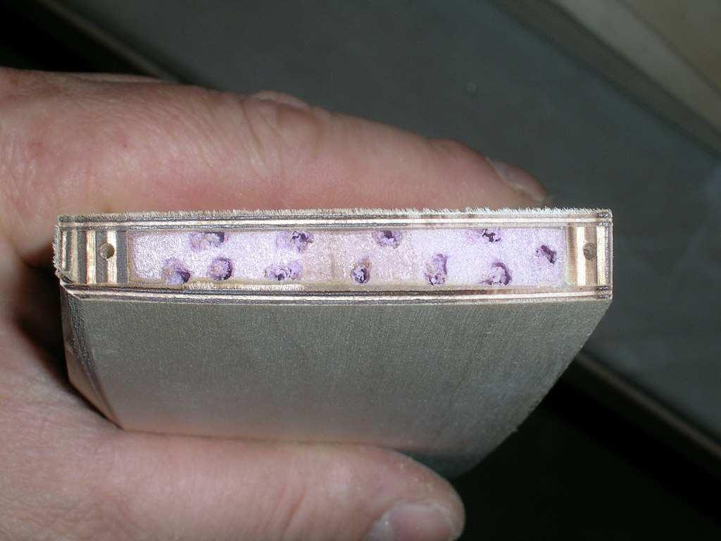
2 Sponson Assembly: These are the most critical parts of the boat, and you guessed it, the most difficult part of the build as well! No need to panic though, it s pretty straight forward if you follow the steps carefully and work with attention to detail and accuracy. Starboard = right side of boat as viewed from the rear. Port = left side of boat as viewed from the rear. What you need to start the sponson build is: - the four (4) ¼ thick sponson frames (sides/stringers) - the four (4) sponson tubes ( ½ O.D.) - two (2) 2 x3 x18 foam blocks For this first step, the sponsons will be upside down on the build table. It is very important here that you use the correct former pieces in the right place, as they look alike but they aren t all the same. Of the four sponson formers, two stand out above the rest. They are the ones with three holes in them for the turn fin mounting. The higher of these two is the inside former (nearest to the tub) of the starboard sponson. The other is the outside former (furthest from the tub) of the starboard sponson. The other two formers are for the port side sponson. The highest is the inside (closest to the tub) former. The other is the outside former (furthest from the tub). * When I refer to closest or furthest from the tub, imagine the sponson installed on the finished boat. It s pretty easy to see which are taller if you run the sponson tubes through them all as shown in the picture below.
 blocks should be placed cut-side down, so that they stand 2 wide, 3 high.")
3 Pair the pieces, one inner with one outer. Mark them as such if it s not already done. Put them top-down on the table with a block of foam between them. The foam (or balsa) blocks should be placed cut-side down, so that they stand 2 wide, 3 high. So for the starboard sponson (the one the turn fin mounts to) it should be like this: with the pieces on the table in front of you, top-down and the back of the sponson to your right, you should have: starting with piece nearest you, outer piece foam inner piece (inner meaning the piece that will be nearer to the tub of the boat). For the port sponson, it should be like this: with the pieces on the table in front of you, flat edge down and the back of the sponson to your right, you should have: starting with piece nearest you, inner piece foam outer piece.

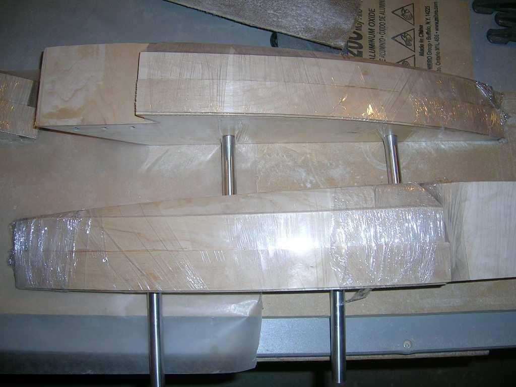
4 Now the fun part! Mix up a batch of epoxy and coat the surface of each piece that will be against the foam block. Then position the pieces to sandwich the foam block and lightly clamp in place until the epoxy sets. Put some wax paper on your work table as it will prevent the sponsons from sticking to it as the glue cures. * In this step you want to make absolutely certain of a few things. First make sure the rear tips of the sponsons are square to one another. Also, you want to make sure everything stays flat against the build surface, including the foam block. This is ABSOLUTELY necessary. It will ensure that the sponson bottoms have the correct dihedral and that the sponson tubes go in straight later on. This is the most important and critical part of the entire build. Repeat for both sponsons.


5

6 Once the epoxy has cured you can use the flush-cut saw and trim the excess foam following the edges of the wood pieces. Don t go too close with the saw, finish with a sanding block. DO NOT CUT OR SAND THE WOOD. If you alter the shape of the plywood pieces, you alter the final shape of the sponsons. These pieces are precisely cut on a CNC to ensure proper angles of the sponsons bottom. If you did these steps correctly, as I m sure you have, you should measure about 1.5 degrees dihedral on the bottom of the sponsons. Measured from the inner piece to the outer piece.

7 Now, it s time to step back and congratulate yourself you ve completed the most important part and are on your way to a very successful build! Let s move on then. Now it s time to drill out the blocks for the sponson pins and the wood dowels. Drill from one side about half way through, then drill from the other side to complete the side-to-side holes.


8 At this point you can install the ½ and ¼ wood dowels for the turn fin mounting area. Here are some pictures of some that were done at a later point in the build but now or later, the end result is the same. You epoxy in the dowels, then center drill the ½ ones with a ¼ bit and thread in the brass inserts. All the dowels pictures here must be


9 installed so that the go through BOTH ¼ thick sponson formers. This is important for maximum strength of the turn fin mounting area.

10 Now take two 1 x3 x18 blocks of foam (or balsa) and epoxy them to the outside of both sponsons with the cut edge of the foam lining up with the flat edge of the sponson. I like to use small pieces of masking tape on the outside formers where the second block is glued on so as to prevent epoxy from getting inside the holes. This makes it much easier later on to get the pins and dowels in correctly.

11 Once the glue is cured, get the sponson top sheeting templat out. This piece is shaped like the top of the sponsons and is made of 1/8 ply. What we have to do now is trace the outline of the outer edge of the sponsons using the template as a guide. The template is actually 1/16 narrower than the final sponson will be this allows for the top sheeting to cover the side sheeting. Position the template on the top of the sponson, lining up the inside edge (the straight one) with the inside ¼ ply of the sponson. Also line up the front of the template with the tip of the sponson. Once in position, take a pencil and lightly scribe the outline (curved side) onto the foam. Flip the template over and repeat on the other sponson.
12 Cut along the outline on a bandsaw if you have one. If you don t have a band saw, you can rough cut with the flush-cut saw or even a jigsaw or scroll saw. Keep the cut as close as possible to vertical and do the final shaping by block sanding. This cut really isn t that critical, so just do the best you can. Test fit the 1/16 top and side sheeting on the sponsons to ensure the top sheet will cover the side sheet. Fine tune with sanding block until you get the fit you want. G. Lockhart from Australia sent in these pictures of a simple sanding jig he made to accomplish this step while keeping the side of the sponson perfectly vertical.


13 * When doing the final shaping of the sponson sides, put the sponsons back-to-back and sand both together to ensure they both end up identical. The important parts to have block sanded at this point are, the top of sponson, the bottom of sponson and the back taper of the sponson.

14


15 Now epoxy the sponson side sheeting to the foam. Line up the straight edge of the ply to the foam at the back and the top of the sponson. Use rubber bands to hold the ply in place while the glue cures.


16 Now you can finish trimming the foam using the edges of the plywood pieces as guides. Block sand lightly.


17

18 Start gluing on the rest of the sheeting. Begin with the small piece covering the lower rear taper of the sponson. Block sand all edges of the pieces as you go once the glue is cured. Follow the sequence as picture below. * When gluing the sheeting on the sponsons, use a brush to apply a coat of epoxy to the entire sheet of plywood. Make sure there will also be glue at the intersections of the different pieces to ensure a strong bond and a tough sponson. I like to use at least 30-min cure epoxy for all the sheeting.


19

20 *** something I discovered while building several of these boats is that the cling wrap or shrink wrap commonly used for packaging works great for holding on the thin ply to the foam while the glue cures. It keeps a nice even tension on the pieces and allows for very tight joints.


21 Side taper


22 Bottom

23 Top


24


25 At this point the sponsons are almost completed. Cut off the excess at the tips of the sponsons and sand them flush. Do them together so they are the same. Now we must install the sponson tips. Make a mark at about ¾ back from the tips of the sponsons. Put both sponsons together side by side to make these lines even. Then cut off the sponson tips at these marks. A table saw works great for this step, but it can easily be done by hand also. Block sand to make sure the ends are nice and straight.


26 Take the short blocks of wood supplied in the kit and epoxy them to the tips of the sponsons and let cure completely. After the glue has cured, use your wood plane and a sanding block to shape the sponson tips to match the rest of the sponson. The sponson tips are made of hardwood, so it will take some time to match them perfectly. If doing this on a belt sander it is pretty quick. If you are doing it by hand however, I suggest using a small hand plane to do the rough removal, then finish by block sanding.

27
28 Now you can install the sponson tubes. You will notice in the picture, I like to rough the surface of the tubes that will be glued inside the sponsons. I also like to cross-drill a hole or two in them. You ll see why in a minute.
 and push them into place. Make sure they go in all the way.")
29 Take the larger wood dowel supplied in the kit and cut it into 4 equal length pieces. Brush some epoxy onto the portion of the aluminum tubes that go in the sponson (and in the holes) and push them into place. Make sure they go in all the way. They will go through the first ¼ plywood and also through the other plywood inside the sponson. Once in place pour some epoxy down inside the tube. Coat the dowel piece with epoxy and insert it into the tube. Use a screwdriver or something similar to push them in all the way. Push them in slowly..you will feel the glue seeping out of the holes in the tubes inside the sponsons. (Don t overdo it though.) This will allow glue to go fill voids, if any, between the foam and the tubes. It will also send glue down to the end of the tube where it crosses the inner ¼ ply. Just a little bit of added strength. Wipe off excess glue around the tubes and let cure. *** NOTE: the sponson pins have some grooves machined into them. If the pins are properly installed (going though both ¼ plywood sponson formers) none of these grooves should be apparent with the pins in place. If some of the grooves are showing, the pins are not in far enough, so recheck and correct the situation.


30


31


32 The final step is to install the ride pads on the sponsons. These line up flush with the inner edge and the back trailing edge of the sponsons. You can blend them in at the tips with a sanding block once the glue has cured or you can trim them square the choice is yours. At the back, let them overhang a little bit and sand them back taper and flush with the back of the sponson on the same angle.

33


34

35 You can now seal the outside of the sponsons. I use West Systems epoxy for this. 105 resin with 207 hardener. This concludes the assembly of the sponsons and the most difficult part of the build!
36 Now the tub! Building the tub is pretty straight forward. The key factor is that you build it straight! You should have a long straight edge (long enough to span the length of the tub) a good square and several clamps (5+ inch span) ready for this step. Again, you should be working on a perfectly FLAT work surface. Dry-assemble the parts on your work surface to begin with and see where everything goes. We start by working with the tub right-side-up. There are three main bulkheads and two pieces that make up the transom. The tub sides are slotted for the bulkheads to fit into place. Test the fit, adjust slightly with sand paper if required. Don t make the slots deeper than they are though, as this will reduce the spacing between the sides and you will end up with less than 4.5 inches. This will make it difficult to get then engine mounts in when the time comes. When you re satisfied with the fit, mix up a batch of 30-min epoxy and apply to the edges of the bulkheads and to the slots in the tub. As with the sponson build, you may want to lay a length of wax paper on your work surface so that the tub doesn t get glued to the table. Use a long straight edge ( I use a long aluminum level ) and clamp it along side of the tub as you glue everything together. Also check that the transom is square with the sides. Continue checking this as you position all clamps. You can also clamp the square to the side/transom if you wish. Make sure everything stays flat against the build table also as the glue cures.


37 You can also glue and clamp the transom doubler in place during this step, or do it after, choice is up to you. I usually do it all at once. After the glue has cured, take your drill with a 1/8 drill bit and using the holes in the sides of the tub as guides, drill into the bulkheads about ¼ to ½ making sure you drill inline with the bulkheads. Take the 1/8 dowel piece supplied with the kit, dip it in glue (I use 30-min epoxy again) and push it into one of the holes until it bottoms. Cut off


38 excess with the flush-cut saw and repeat for all holes in bulkheads. After the glue has cured, block sand all dowels flush to the sides.


39 At this point you are ready to start installing the 1/16 sheeting on the tub. *** Use a piece of 4.5 wood between the sides at the tip of the boat as a spacer just to keep the sides at the correct spacing when gluing on the sheeting just do not glue the piece into place. You can use the rear boom-tube hardwood block supplied in the kit.

40 Start with the bottom sheeting. This is the longest continuous piece of 1/16 plywood. Put the tub upside down on your table. Use 30-min epoxy to coat all the edges of the sides and bulkheads/transom. Since the 1/16 plywood is so glossy finish, I recommend roughing it up a little bit with coarse sandpaper where it will make contact with the tub to ensure a good bond. Clamp a straight edge along one side of the tub to keep everything straight. Also make sure it is square at the transom. Place the sheeting on the bottom of the tub. The piece will overhang the entire tub so you have some wiggle room here to get a nice fit all around. When satisfied, clamp, tape and/or weigh it down to ensure good contact between it and all sections of the tub until the glue cures. Let sit until completely cured. Again, very important to do this on a FLAT surface if you do not want a twisted tub! Now is a very good time to install the radio box doublers. These are two pieces of 1/4. You can install them after putting on the top sheeting, but it is much easier to do it now. I like to have them staggered in the radio box as pictured below. Seal them completely with epoxy and try to get a good bond with the bottom of the boat and to the sides/bulkheads of the tub.

41 You should also install the hardwood rear boom tube support. This is the 4.5 long block with bevelled edges on the bottom. The bevelled edges it to allow the block to sit flat in place even if there is a little bit of epoxy filets from gluing the bulkheads and sheeting into place. Test fit this piece and ensure it sits flat in the bottom of the hull and that it also makes good contact with the bulkhead. Coat it with epoxy on the bottom, rear face and both ends and position it into the boat making sure it stays in good contact with the bottom and bulkhead. You want this entire piece to be sealed with epoxy.


42 Take the boom tubes and mark the center on both of them. Then make two marks at 1-1/8 on either side of the center mark. Drill a 5/32 hole at each of the marks off center. Take one of the tubes and position in the hull and in the rear position and center it. Using the holes in the tube as guides, drill holes in the support block.


43 Drill completely through the block and bottom of the hull. The buttonhead screws will go in from the bottom of the tub though the boom tubes and be capped off with locknuts inside the hull.


44 Now take the other boom tube and position it in the tub in the forward position. Again center it in the tub. Using the holes in the tub, drill through the bottom of the hull. Temporarily install the mounting bolts. With the bolts in place but not tightened, find one of the 1/8 thick shims supplied in the kit. Apply some glue to the bottom of it and slide it under the boom tube. Screw the nuts onto the bolts and tighten until snug. Let cure.


45 When everything is cured, remove the boom tubes and hardware and mix up a good batch of epoxy to seal the inside of the tub. I use West Systems epoxy for sealing. Usually I will use 206 or 205 hardener with 105 resin. I will typically also add a small amount of acetone to thin out the epoxy for better penetration in the wood. DO NOT use too much acetone...it can weaken the epoxy and the existing joints. A very little bit goes a long way.

46 You can now flip the tub over and prepare to install the top sheeting. Before installing the top sheeting, get the access cover frames from the parts and glue them onto the underside of the top sheeting. If positioned correctly, these will create a lip about 1/8 wide to hold the access covers. Some frames are supplied with the inside not removed. If this is the case with your kit, cut the holding tabs and remove the inside from the frames. Sand off the holding tabs on the frames being VERY careful not to break the pieces. The frame that is cut cross-grain will be much more flexible than the other two. This frame is for the front access cover. *** You also have to seal the entire underside of the sheeting pieces at this point before installing them to the tub. Again I use West System for this. For this step however, I DO NOT thin with acetone. I coat the underside of the entire sheeting pieces and the edges of the tub and apply the sheeting to the tub. You should sand the sheeting where it will make contact with the tub for proper adhesion of the epoxy.


47 You can also do this in two steps, but if you let the sealing coat dry you will have to lightly sand the sheeting where it will make contact to the tub to ensure a good bond. Clamp, tape and/or weigh down the sheeting for good contact to the tub until glue cures.


48 After glue has cured you can proceed to sanding the edges of the sheeting to match the sides of the tub.

49 Now trim the nose of the tub by removing about ½ from the tip of the tub. Use pieces of ¼ square stock to frame the inside of the nose as pictured below. It will help keep the thin plywood flat and straight and also add a lot of surface for gluing the nosepiece to. Glue on the hardwood nosepiece with slow cure epoxy and let cure.


50 When the glue has cured, shape the nose piece to match the tub. It should look something like this.


51 Inside view


52 We can now do the rear shoes. These a CNC cut to shape already. All that is required is that you glue the 1/16 ride pads to them and then sand a ¼ bevel to the outside lower edge of each. They should look something like this. Mount the rear shoes to the tub with 30-min epoxy. They should be mounted to that the beginning of the back taper is flush with the back of the transom. The sides of the shoes

53 should be flush and parallel to the sides of the tub. The shoes must be mounted with their bevelled edge on the outside. NOTE: make sure the shoes do not extend past the back of the transom more than 1-1/16 in order to have proper clearance for the rudder. If required sand the back of the shoes square to obtain the required clearance. This completes the assembly of the tub. All the remains to be done now is to seal any wood that has not already been sealed. I use West Systems 105 resin with 207 hardener for the outside of the tub.


54

55 Cowl The cowls are made of epoxy glass and are delivered roughly trimmed. The still require that you trim, sand and paint them. Included with the cowl is a trim piece that looks somewhat like a hockey stick. This is to be installed (glued or screwed) to the carburetor side of the tub and serves as a rest for the cowl and also as a water deflector to prevent water from creeping in between the cowl and the tub. Here are a few pictures of an installation to give you some ideas on how to mount your cowl.


56

57 Setup Now it s time to setup your Warpath. You will have to first install the boom tubes in the hull. The rear boom tube should already be ready. Repeat the same for the front boom tube, this time though, drill through the bottom of the hull and install the 1 ¼ bolts with washers from the underside of the tub and through the boom tube. Secure with the nylock nuts over the boom tube. There is a 1/8 plywood shim supplied in the hardware bag this goes under the front boom tub. Seal it before you install it. This will take up the space between the tub bottom and the tube.

58 Now it s time to install the sponsons to the boom tubes. Slide the sponsons on and set the boat on the table. You want to set the starboard sponson with 1/8 of toe-in and the port sponson 1/16 toe-in. To make this job easier I use blocks that I cut to the correct length. I start with the starboard sponson. With the spacer blocks in place (5-1/2 at the rear boom tube and 5-3/8 at the front tube) I use some long clamps to lightly pull the sponsons tight to the blocks. Center punch the hole locations and drill straight through with a 5/32 drill bit. Install the supplied 8-32 bolts and nuts. Repeat on the port sponson, using 5-7/8 spacing at the rear tube and 5-13/16 at the front.


59


60
61 Hardware We recommend using Speedmaster strut and rudder. For the strut we recommend the SPDS HR 1/4" Strut XTD assembly (strut brackets should be 2 long) For the rudder we recommend the SPDR-013-1SB or the SPDR SB, 60/90 Rudder Assembly. Both of these seem to work equally well on the boat. Mount the strut on the center of the transom with the brackets about ¼ from the bottom of the tub. Mount the rudder on the port side of the transom with the bracket butting up against the strut s bracket and at the same height. The rudder bracket will overhang the edge of the tub about 1/16 or so. That s ok. If you want, you can bevel the edge of the bracket that is overhanging. I don t cut the rudder on my Warpath, but you can experiment if you want. (You can probably cut off up to about an inch safely.) To mount the engine, we use CC Racing standard mounts but replace the stock rubber isolators (which are ¾ long) with ½ long isolators. You can get them from places like McMaster Carr ( p/n: 9378K24). Mount engine as far forward as possible in the engine compartment. The stuffing tube will go through the front of the radio box and exit the hull through the bottom of the radio box between the two doublers. Your gas tank or IV bag goes in the front compartment of the tub, just forward of the engine compartment. I use a 250ml IV bag. It fits nicely in that compartment and still allows sufficient room to squeeze in a Etrex GPS. The turn fin is supplied with the kit. It should be sharpened with a taper of about 3/8 as straight as possible. Mount the fin (with the supplied bolts and washers) after having done the strut and sponson adjustments below. Start with the fin level with the ride attitude of the boat and tune accordingly once at the lake. Lifting the back end of the turn fin will make the boat tighter. Dropping the back end of the fin will do the opposite, making the boat looser. * if the turn fin is not properly sharpened it will create a lot of drag and cause the boat to pull right at speed, so make sure you get a nice sharp edge on the fin. Props: I have had very good success with cupped up ABC 3014 and 3016 so this is a good place to start. Propworks and Propworks West both have developed some VERY good props for the Warpath.

62 Preliminary adjustments Set your warpath on a setup table the table must be perfectly flat, wide enough for both sponsons to sit on the table and long enough for the rear shoes to sit on table also. Start with a 1/8 shim under the rear tube. We have found this to be a very good starting point on most boats. For heat racing you might need to shim a little bit more to keep the boat tight in the rough water conditions. Set the strut so that it is 1 from the bottom of the transom (not the shoes) to the bottom of the strut. Adjust it so that it has 0 degrees angle, so in other words, flat against the setup table. Again this has shown to be a very good starting point for the strut. This of course is prop-dependant. Now take a piece of 1/16 plywood (you should have a few pieces left over from the kit) and slide it under one sponson s ride pad. Hold it flat against the table and slide it back slowly toward the back of the sponson until you see/feel it touch the ride pad. Check this a few times to be certain. Measure the distance between the edge of the ply that is touching the ride pad and the trailing edge of the sponson. You want this to be about 1-1/8. Check both sides. You want both sponsons to be the same. This is a good starting point. If it is not correct, use the supplied shims ( or remove shims ) under the rear boom tube to adjust. Tighten the boom tube bolts and check again. You can shim both sides of the boom tube differently if required to get the proper angle on both sponsons. Note on tracking: assuming your turn fin is properly sharpened and aligned, if you find the boat pulls to ones side with the rudder set straight, you can try adding additional shims under the rear boom tube on the side opposite to the pull.

63 With this correctly done, you should be ready to head out to the lake to try out your Warpath! At the lake Make sure you go over everything to ensure all nuts and bolts are in place and tightened. Test fire you engine. Range-check your radio. Don t be in a hurry. Put all the odds on your side for a successful first run! It is preferable that you have a pit man with you at the pond, as launching a rigger by yourself can be very tricky, not to mention dangerous. Try to launch the boat as flat as possible while giving it a good push forward. If you re lucky the boat will run great first time out, but as with any boat, you can usually get more out of them with more fine-tuning. If you have any issues with the way your Warpath is handling/running, please post on our forum and we will help you sort it out. There are too many combinations of symptoms and solutions to list here really. I prefer we work issues out on the forum if any and that way the information can be useful to all members.
64 Thank you for choosing the Warpath. Happy Boating!!!
FireFighter.21 Building Instructions
 A Tom Moorehouse design. Thank-you for purchasing the FireFighter.21. I believe that you will find it to be the best.21 rigger kit available. It has won 1 st place in the 2006 AMPBA nationals! It was designed
JAE Mini Sprint. Fast Electric Outrigger. A Zippkits R/C Boat. Building Instructions
 Z I P P M A N U FA C T U R I N G JAE Mini Sprint Fast Electric Outrigger A Zippkits R/C Boat Building Instructions 2011 Zipp Manufacturing - Frankfort, New York 13340 www.zippkits.com Toll Free (866) 922-ZIPP
FUSELAGE CONSTRUCTION
 FUSELAGE CONSTRUCTION Note: prior to building and gluing on the work surface use protective covering on your building surface. (wax paper or clear wrap) Fit the laser cut Fuselage Front and Fuselage Rear
Piper Cherokee /3 scale. Construction Manual
 Piper Cherokee 140 1/3 scale Construction Manual STAB CONSTRUCTION 1. Remove foam cores from cradle and place on flat surface. Inspect pieces before you epoxy halves together making sure leading and trailing
Slide the stock rubber tank mount caps onto the ends of the CS-1 tank mount:
 RYCA CS-1 BODY PARTS INSTALLATION GUIDE [The CS-1 installation guides should be used as supplements to the videos found on our Youtube Channel. There is no strict order to the build process, but it is
Continue gluing the remaining top parts ensuring the angled piece is glued well. Set aside and let dry. See photo below
 Radiator rev 1.1 The SE5a s radiator is one of the most recognized radiators in WW1. It is one of the components that defines the SE5a. The original SE5a has seen multiple radiator designs used during
4. Bevel the LE face of HS1-HS11 to match the horizontal stab leading edge sweep angle.
 BEFORE YOU BUILD 1. Unroll each sheet of the plans. Roll them inside out so that they will lie flat on the building surface. 2. Assemble the tools that you will need to build each section so that they
THE APOGEE A 100-INCH AMA DURATION SAILPLANE FROM DYNAFLITE
 THE APOGEE A 100-INCH AMA DURATION SAILPLANE FROM DYNAFLITE Apogee is the intermediate sailplane designed to be competitive in AMA duration contests. Effective spoilers, rudder and full flying stabilizer
Hobby Lobby Zip Supplementary instructions Please refer to the included drawings while using these assembly instructions
 Materials needed: 15 or 30 minute epoxy Medium CA Masking tape Scotch tape Servo Tape Wax paper Tools Needed: Pencil or marker Flat building surface Hobby knife or razor blade 7/64" or 3mm drill bit 3/16"
JAE12G4 Hybrid A Zippkits R/C Boat
 Z I P P M A N U FA C T U R I N G JAE12G4 Hybrid A Zippkits R/C Boat Building Instructions 2014 JMP Hobby Group LLC Indiana USA www.zippkits.com Toll Free (866) 922-ZIPP 1 The JAE series was designed and
Installation for Full Size Polaris Ranger Crew Doors
 Installation for Full Size Polaris Ranger Crew Doors Order of Installation: Heater Doors Wiper on to Windshield Windshield Top & Back Panel Note: Most of the steps in these instructions need to be repeated
C-180 Builder s Manual
 C-180 Builder s Manual. May 20, 2002 Last revised July 11, 2002 Copyright! 2002 Douglas Binder, Mountain Models www.mountainmodels.com sales@mountainmodels.com (719) 630-3186 1 Required Equipment! Xacto
12. Wings, Flaps, Ailerons and Struts
 12. Wings, Flaps, Ailerons and Struts Fit Aileron Hinges Reference: Drawing 20270K2 Photo 12.1 Parts Required: 2007092 Aileron LS 200809N Aileron RS 2001394 Hinge 3/16 A1 (4) 2001694 Hinge Pin (4) PH0059N
JAE21OB. 3.5cc Outboard Outrigger A Zippkits R/C Boat. Building Instructions Zipp Manufacturing - Frankfort, New York
 Z I P P M A N U FA C T U R I N G JAE21OB 3.5cc Outboard Outrigger A Zippkits R/C Boat Building Instructions 2012 Zipp Manufacturing - Frankfort, New York 13340 www.zippkits.com Toll Free (866) 922-ZIPP
SE5a Instrument Board part 2 - rev 1.1
 SE5a Instrument Board part 2 - rev 1.1 Fuel (Petrol) Valve This valve uses two circular name plates, eight brass screws, one black plastic base, copper wire and two black plastic risers. You can pick any
PITTS S2S CONSTRUCTION
 PITTS S2S CONSTRUCTION FUSELAGE CONSTRUCTION 1) Place the right fuselage side over the plan and mark the former positions. Place the left side over the right side and mark the former positions. Glue F1
RFS Class II Rocket Assembly Instructions
 RFS Class II Rocket Assembly Instructions Instructions by: Loc Precision Photos by: Great Lakes Space Port Sheboygan Education Foundation, Inc. Welcome and thank you for joining the Rockets for Schools
Tools and Tips: ( 1 )
") Tools and Tips: As you build instructions will show in my many picture manual how to assemble. You can use your own methods as you desire, my results are very good. A smooth, flat work surface is very
Tools and Tips: As you build instructions will show in my many picture manual how to assemble. You can use your own methods as you desire, my results are very good. A smooth, flat work surface is very
Front Vise 70G G08.02
 Front Vise 70G08.01 70G08.02 The following instructions guide you through the installation of either the Regular Front Vise (70G08.01) or the Large Front Vise (70G08.02). The first step is to determine
Hinge Mortising Jig. One of the make it or break it parts of building a. 6 ShopNotes No. 74
 Hinge Mortising Jig A Mortise for a Hinge. Quick, clean, and accurate that s the only way to describe the mortise you get with a trim router and this hinge mortising jig. One of the make it or break it
Building Instructions
 ZIPP MANUFACTURING Kently Porter after smashing several IMPBA records with his JAE 21 JAE21G2 A Zippkits R/C Boat Building Instructions 2009 Zipp Manufacturing - Frankfort, New York 13340 www.zippkits.com
SZD-10 bis CZAPLA ASSEMBLY MANUAL IN PICTURES
 1 RUDDER Plan and parts: 2 Assembly steps: Photo above: glue together rudder spar, ribs and trailing edge. Clamp spar to a flat surface (chipboard on the photo) and make sure the straight aligment of the
Note - the nose ribs and are thinner than the main ribs. These nose ribs will use a thinner rib cap than the ribs. This is per design.
 Stabilizer rev 1.2 The SE5a stabilizer is the heartbeat of the tail and is recreated like the full scale version. All tail pieces depend on the stabilizer. It uses the steel fittings, pulleys, inspection
Making your Rudder Cassette
 Making your Rudder Cassette A list of the stuff you ll need The row of materials below is laid out in the order of application. The foam blank shown on the right is available from Bob at www.flyingfoam.com
REVISION LIST CHAPTER 25: AFT WINDOWS. The following list of revisions will allow you to update the Legacy construction manual chapter listed above.
 REVISION LIST CHAPTER 25: The following list of revisions will allow you to update the Legacy construction manual chapter listed above. Under the Action column, R&R directs you to remove and replace the
For Barrel Tapers. Installation and Operating Instructions For use with small combination belt & disk sanders. Assembled Taper Tool
 Tim s Taper Tool For Barrel Tapers Installation and Operating Instructions For use with small combination belt & disk sanders Assembled Taper Tool Your taper tool is capable of making barrel tapered shafts.
Tools and Tips: ( 1 )
") Tools and Tips: As you build instructions will show in my many picture manual how to assemble. You can use your own methods as you desire, my results are very good. A smooth, flat work surface is very
Tools and Tips: As you build instructions will show in my many picture manual how to assemble. You can use your own methods as you desire, my results are very good. A smooth, flat work surface is very
10. Wing prep and subassembly
 Date Section Objective: Construct and fabricate the sub-assemblies of the wing panel. Required Parts: Wing left 11gal PN104-300, Wing right 1gal PN104-400, Wing left 15 gal option PN104-322, Wing right
RESolution V2 Manual
 RESolution V2 Manual Note for the German Manual: Yellow Bottle thick CA Pink Bottle Med CA Blue tube 5 minute Epoxy Green tube 90 Minute Epoxy Construction of the Fuselage Step 1: Cover the plan with a
After the canopy hinge is square with the firewall and the nut plates are installed you can set up the hinge mounts. Start by clamping a 1/16 tongue
 Written by: Sean Cole September 19, 2008 When fitting the stiffener use 3/32 clecos to hold it in place, it makes a smaller hole and is easier to work with. Only use the amount needed to hold the stiffener
JAE 33FE. Copyright 2017 JMP Hobby Group LLC Indiana USA. Competition Electric Outrigger Hydroplane
 JAE 33FE Competition Electric Outrigger Hydroplane Manufactured exclusively by Zippkits in the United States Zippkits.com Toll Free (866) 922-ZIPP 9477 Copyright 2017 JMP Hobby Group LLC Indiana USA 1
TIGER MOTH 120 ASSEMBLY INSTRUCTIONS
 TIGER MOTH 120 ASSEMBLY INSTRUCTIONS SPECIFICATIONS Wing Span: Length: Radio: Flying Weight: 1920mm 1580mm 4 channel with 6 servos 4200g AILERON ASSEMBLY 1 Start by removing the servo cover from the bottom
Parts Identification
 We are excited to introduce the Model Aero Aqua Sport. This is an excellent sport flyer, equally at home flying from grass fields, water, or even snow! The unique V-tail gives the Aqua Sport a distinctive
Hatch Installation For Pygmy Solo and Double Kayaks
 Introduction/Overview Hatch Installation For Pygmy Solo and Double Kayaks The hatch kit consists of several wooden lips, strapping and hardware. The hatch is constructed by cutting a hole in your deck,
Cobra X Q Construction Tips Construction: Bel y pan
 Cobra X Q Construction Tips : The white plastic in this kit is high impact styrene. It can be painted with most types of coatings if light coats are applied this is necessary due to the thickness of the
Jabiru Aircraft. Fit Ailerons
 Fit Ailerons Reference: Drawings 2033091 and 20210K1 Photos Parts Required: 2021091 Wing LS 202209N Wing RS 2027092 Aileron LS 202809N Aileron RS 2036034 Aileron reinforcement Left 203703N Aileron Reinforcement
Plastic Trainer-19. I have tried to only use materials available from the big box building centers like Home Depot, Rona (Canada) and Lowe s.
 and Lowe s.") Plastic Trainer-19 I have tried to only use materials available from the big box building centers like Home Depot, Rona (Canada) and Lowe s. The picture above shows the prototypes with an original Cox
Plastic Trainer-19 I have tried to only use materials available from the big box building centers like Home Depot, Rona (Canada) and Lowe s. The picture above shows the prototypes with an original Cox
96 WING SPAN SPITFIRE (COPYRIGHT PROTECTED 2014) ALL RIGHTS RESERVED
 ALL RIGHTS RESERVED") 96 WING SPAN SPITFIRE (COPYRIGHT PROTECTED 2014) ALL RIGHTS RESERVED GENERAL INSTRUCTIONS Should you elect to use the recommended Door Skin, which is 1/8 mahogany plywood measuring 36 x 88. Have it cut
96 WING SPAN SPITFIRE (COPYRIGHT PROTECTED 2014) ALL RIGHTS RESERVED GENERAL INSTRUCTIONS Should you elect to use the recommended Door Skin, which is 1/8 mahogany plywood measuring 36 x 88. Have it cut
ParkJet Builder s Manual
 ParkJet Builder s Manual Thank you for purchasing the ParkJet. The ParkJet is a profile ducted fan airplane that can be flown in a larger park. The ParkJet was initially designed by Scott Stoops and modified
Building Tips This model can be built using the following types of adhesives:
 Page 1 Building Tips This model can be built using the following types of adhesives: Epoxy (with or without microballons) Odorless cyanoacrylate (CA) with accelerator UHU Creativ for Styrofoam (or UHU
Step by Step Wing Bagging
 Step by Step Wing Bagging By Evan Shaw 073 589 9339 evanevshaw@gmail.com Preparing the Leading Edge 1. Cut cores. (Cutting of wing cores is covered in another article elsewhere) 2. Sand the LE to a nice
SE5a Wing Panels rev 1.0
 SE5a Wing Panels rev 1.0 The top and bottom wings are different. They might look the same but the bottom wing has one less rib and some rib spacing difference. This is due to where the wooden interplane
Competition Outrigger Hydroplane for.21 engines
 JAE 21GT Competition Outrigger Hydroplane for.21 engines This latest version of our world record holding outrigger has been optimized for heat racing by Martin Truex, Jr. Manufactured exclusively by Zippkits
RSM DISTRIBUTION Presents
 RSM DISTRIBUTION Presents MOSQUITO By Jack Sheeks Photo _ Jack Sheeks Semi Scale Twin Stunter Wing Span: 58" Length: 37-3/4 Area: 579 sq. in. Engine: Two.35 -.40 www.rsmdistribution.com Call (951) 678
SASKATOON, Saskatchewan
 CONSTRUCTION GUIDE AVRO ARROW (CONTEST VERSION) Copyright, Bill Jones, 2004 SASKATOON, Saskatchewan This is a work in progress, so there are a couple of rough areas ( I ll point out those that I m aware
SPUNKY ASSEMBLY MANUAL
 SPUNKY ASSEMBLY MANUAL Please read the tips section at the back of this manual regarding the use of laser cut parts. The proper removal and preparation of these parts is important. When laser cut, some
Citabria Pro. Aerobatic Parkflyer. by Joel Dirnberger
 Citabria Pro Aerobatic Parkflyer by Joel Dirnberger Revision C: December 21, 2004 Citabria Pro Building Instructions Length: Wingspan: Wing Area: Flying Weight: Wing Loading: Functions: Specifications:
Fokker Dr1 Master Instructions
 Fokker Dr1 Master Instructions Rev 1 Congratulations on your new project. This Dr1 kit is the finest to date. The construction of the plane is similar and exactly like the original. Take your time and
How to install backchecks
 How to install backchecks Note: All pictures can be enlarged for better clarification. Revision 7 8/2009 Backchecks wear out in a piano much like brake pads in an automobile. While wear is a valid reason
Dandy Sport Builder s Manual
 Dandy Sport Builder s Manual Thank you for purchasing the Dandy Sport. The Dandy Sport has been designed as an easy to build aileron trainer. Take your time and enjoy building this plane. Specifications:
Shoulder Plane. dovetailed. fine tools. Make an heirloom tool and learn the secret to creating double dovetails in metal it s easier than you think.
 fine tools dovetailed Shoulder Plane Make an heirloom tool and learn the secret to creating double dovetails in metal it s easier than you think. I ve always been fascinated by old, metal hand planes.
Redwood strips are tacked to the templates, and edge-glued. Drive brads through into the templates before putting on fiberglass doth.
 1 Make the building form and attach templates to the crosspieces. Nail a strip down the center to hold the stems and templates in position. prototype canoe took about three weekends to build. She's broad
*Patent Pending. *Trademarked. Series II. Glass Conversion Kit. (888) One-Products (888)
 One-Products (888)") *Patent Pending *Trademarked Series II Glass Conversion Kit www.onepieceproducts.com (888) One-Products (888) 663-7763 Installation Manual Full One Piece Door Glass Conversion Kit Series II 1967-1972 Chevy
*Patent Pending *Trademarked Series II Glass Conversion Kit www.onepieceproducts.com (888) One-Products (888) 663-7763 Installation Manual Full One Piece Door Glass Conversion Kit Series II 1967-1972 Chevy
LARK. Classic Legal Precision Stunter RSM DISTRIBUTION. presents. Charles Mackey. Wing Area 570sq. Wingspan 52.
 RSM DISTRIBUTION presents LARK By Charles Mackey Photo _ Bob Hunt Classic Legal Precision Stunter Wingspan 52 Length 39.5 Wing Area 570sq Motor 35-46 www.rsmdistribution.com Page 2 Thank you for purchasing
Cockpit Kit. Full Depth - Builds Quickly - Light Weight READ THROUGH THIS INSTRUCTION MANUAL FIRST. IT CONTAINS IM- laser cut wood kit
 The Savage Light Sukhoi Su- 27 Cockpit Kit contains everything you need to build a full depth semi scale Su-27 cockpit, yet adds less than an ounce to your finished model s weight (not including pilot).
84 WING SPAN MESSERSCHMITT BF-109
 84 WING SPAN MESSERSCHMITT BF-109 (COPYRIGHT PROTECTED 2014) ALL RIGHTS RESERVED MEISTER 84 ME-109 SIERRA GEAR UPDATE PLEASE NOTE: THE MAIN GEAR MOUNTING PLATE FROM SIERRA IS NOT SQUARE. YOU HAVE TO ROUND
 America s leading woodworking authority To download these plans, you will need Adobe Reader installed on your computer. If you want to get a free copy, visit: http://adobe.com/ reader. Having trouble downloading
Australian Vintage Radio Society Inc.
 Australian Vintage Radio Society Inc. (Incorporated in Victoria A0050003S) P.O. Box 3099, Syndal L.P.O., Victoria, 3150, Australia. Cabinet assembly instructions for the AVRS 10 th Anniversary construction
GENERAL NOTES: Page 1 of 9
 Laminating A Zia Into A Turning Blank by W. H. Kloepping, Jan. 2009 This describes how a zia (the New Mexico state symbol) can be laminated into a turning blank. Materials needed: Square Turning Block
FLITZEBOGEN-2 Assembly instructions
 FLITZEBOGEN-2 Assembly instructions Trim the end of the fuselage to the length of 925mm from the nose. Be careful to avoid splitting the carbon fibers. Sand the base of the stab mount in preparation for
Silverware Chest Plan
 Silverware Chest Plan 05L14.01 Introduction 1. Measure the space required for your cutlery before beginning this project to be sure that it will fit in the drawers and top compartment. The best way to
For Barrel Tapers. Installation and Operating Instructions for use with table saws and large disk sanders
 Tim s Taper Tool For Barrel Tapers Installation and Operating Instructions for use with table saws and large disk sanders Your taper tool is capable of making barrel tapered shafts. The term barrel is
Kam Aero 43% Extra 300.
 Stab Sheeting Kam Aero 43% Extra 300. Stabs / Elevator: Make your skins using the same method as you did for the fuselage foam parts. The stabs require 8 sheets (4 per stab) of 4 x 48 A grain sheeting.
Central New York Rocket Team Challenge 2018 Rocket Assembly Instructions
 Central New York Rocket Team Challenge 2018 Rocket Assembly Instructions Note: These instructions vary from those provided by the manufacturer of the rocket kits. There is also considerable varying discussion
SGTalon s Enterprise-A Foamie Build Guide. SGTalon s. Enterprise. Enterprise--A. Assembly Instructions
 SGTalon s Enterprise SGTalon s Enterprise--A Enterprise Assembly Instructions Page 1 4-13-2013 SGTalon s Enterprise *******Recommended Hardware******** 2.6oz 250w Motor and Speed Control with 8x6 prop
Ford Pick Up Rear leaf Spring Kit Installation Instructions
 1948-1956 Ford Pick Up Rear leaf Spring Kit Installation Instructions 1-800-984-6259 www.totalcostinvolved.com Parts 48 inch leaf (2) springs (4) U-bolts 3/8-24 x l 1/4bolts (16) & nuts (2) 1/2-20 x 4
LUNAR EXPRESS. Little
 Little LUNAR EXPRESS The Little Lunar Express kit contains all the parts necessary* to build a flying high power rocket: 1) Pre-slotted boattail 1) Airframe 5.5" long 1) Nose cone 2) Main fins 2) Stabilizer
Corvus Racer CC
 Corvus Racer 540 35CC Item No:L-G035008 Specifications Wing Span Length Wing Area Flying Weight Glow Gasoline Electric Radio mm mm 1200sq in (77.4sqdm) 9.9-12lbs(4.5-5.5kg) 91-1.20(2C) 1.10-1.40(4C) 20-40cc
woodworkersjournal.com MATERIAL LIST
 MATERIAL LIST T x W x L 1 Legs (2) 1 1 2" x 3 1 2" x 36 7 16" 2 End Uprights (2) 1 1 2" x 3 1 2" x 32 1 2" 3 Stringers (4) 1 1 2" x 3 1 2" x 42" 4 Top Cladding, Long (2) 3/4" x 7 1 4" x 65 3 4" 5 Side
Pre-Paint>Fuselage>Empennage>Fit elevator. Objectives of this task: Materials required: Prepare the horizontal stabiliser and the elevator
 Pre-Paint>Fuselage>Empennage>Fit elevator Objectives of this task: To fit the elevator to the horizontal stabiliser, to fit the trim tabs to the elevator and the end caps to the elevator and the horizontal
Nanton Grain Mill Assembly
 ( 1 ) Nanton Grain Mill Assembly Locate package for assembling storage building. These are cut from 1/8 masonite. Inspect and lightly sand edges where it will be bonded. Use white glue or CA glue to bond.
The following pages replace pages 7 thru 14 in the current printing of BUILDING THE PT ELEVEN. (As of December 2012.)This is a modified method for
This is a modified method for") The following pages replace pages 7 thru 14 in the current printing of BUILDING THE PT ELEVEN. (As of December 2012.)This is a modified method for gluing puzzle joints that we believe is simpler than the
The following pages replace pages 7 thru 14 in the current printing of BUILDING THE PT ELEVEN. (As of December 2012.)This is a modified method for gluing puzzle joints that we believe is simpler than the
JAMISON SPECIAL. Building Guide
 JAMISON SPECIAL Building Guide WING Mark then drill holes for wing jig rods. Slide Ribs onto jig rods Mark the rib positions on 1/16 x 1 trailing edge, 1/4 x 1/4 leading edge & 1/4 x 1/4 spars Pin ribs
Robert Bosch GmbH. Minimalist washstand
 Minimalist washstand Neat and tidy Minimalist washstand Minimalist design in the bathroom is in fashion. And rightly so, as this washstand proves: because less is more! 1 Introduction Here s an idea to
Pre-Paint>Wings>Fit ailerons. Objectives of this task: Materials and equipment required: Size the ailerons and pre-mould strips
 Pre-Paint>Wings>Fit ailerons Objectives of this task: In this task the ailerons and the pre-mould strips will be sized and trimmed, then flocked onto the wings and glassed in place, and the next day the
Installing your new Bevella Top. L Shaped Countertop with Joints No Finished Ends (Fits Between Four Walls)
") Installing your new Bevella Top L Shaped Countertop with Joints No Finished Ends (Fits Between Four Walls) Bevella RTI Countertops are engineered and manufactured to the highest quality standards, built
Installing your new Bevella Top L Shaped Countertop with Joints No Finished Ends (Fits Between Four Walls) Bevella RTI Countertops are engineered and manufactured to the highest quality standards, built
Falke Build Instructions
 A totally unofficial translation of the Falke Build Instructions The Falke (falcon) mini DLG is produced and marketed by Modellbau Thiele, Germany (www.modellbau-thiele.de), email webmaster@modellbau-thiele.de.
Fokker D8 Master Instructions
 Fokker D8 Master Instructions Rev 1 Congratulations on your new project. The Fokker D8 is a marvellous subject that highlights the success of a monoplane design. The construction of the plane is similar
JK Front Crusher Flares
 INSTALLATION INSTRUCTIONS INST-17-03-030_A JK Front Crusher Flares IMPORTANT: Thank you for purchasing this Poison Spyder product. Please read through this entire document before proceeding with installation.
Stearman PT-17 KIT WARRANTY
 Stearman PT-17 KIT # K-306 Assembly Instructions Version 2 02-17-16 Designed by Tom Herr WARRANTY Sig Manufacturing Co, Inc. guarantees this kit to be free from defects in both material and workmanship
Introducing The Cloud Models Westland Whirlwind
 Produced by Cloud Models,Deopham Road,Morley,Wymondham, Norfolk,NR18 9AA E-mail sales@cloudmodels.com web site cloudmodels.com Introducing The Cloud Models Westland Whirlwind By Tricks Thank you for purchasing
YJ DeFenders. These installation instructions apply to the following Poison Spyder products:
 INSTALLATION INSTRUCTIONS INST-13-02-070_A YJ DeFenders IMPORTANT: Thank you for purchasing this Poison Spyder product. Please read through this entire document before proceeding with installation. If
Bluenose II Part 2. Planking the Hull
 Planking the Hull Planking is time consuming and requires care, but it can be very satisfying to watch your creation take shape. It is also the point at which many would-be ship modelers throw up their
Contents. pages 20-24: Installing Edge sinks into. custom laminate countertops page 8: Installing Edge sinks into postform laminate countertops
 Contents pages 2-8: Installing Edge sinks into custom laminate countertops page 8: Installing Edge sinks into postform laminate countertops pages 9-14: Installing Acrylic sinks into custom laminate countertops
Chapter Six. Getting started inboard. Installing the false deck
 A close look at the thinning down of the bulkhead extensions. They are just 1/16 thick after fairing them. Chapter Six Getting started inboard This next step is one of the last remaining messy tasks to
PARTS INCLUDED IN FIXED STAIR CABLE RAIL KIT:
 175 SERIES FIXED STAIR CABLE RAIL - INSTALLATION INSTRUCTIONS PARTS INCLUDED IN FIXED STAIR CABLE RAIL KIT: FIXED STAIR TOP RAIL (1) A FIXED STAIR BOTTOM RAIL (1) B D UPPER SADDLE BRACKET (1) C BRACKET
MECOA EZ-4061 Trainer
 MECOA EZ-4061 Trainer EZ-4061 is a newly designed, Almost Ready to Fly kit. It is an extremely easy to control trainer with strong construction and excellent aerodynamic performance. This is a great choice
WOOD TOY NEWS SANDING DRUMS & JIGS ISSUE
 WOOD TOY NEWS SANDING DRUMS & JIGS ISSUE toymakingplans.com June 11, 2014 Wednesday How to Make a Sanding Drum Jig for Smarter Toymaking. By Imants Udris Udie Our discussion begins based on the 5 piece
Extendable Large Dovetail Jig
 Extendable Large Dovetail Jig Instruction Manual Part # 3458 CAUTION: Please read, understand, and follow all manufacturers instructions, guidelines and owners manuals that come with your power tools.
LANIER - Ultimate Pitts - INSTRUCTIONS. Additional Parts Required. (12) 4-40 blind nuts (Dubro #606)
 4-40 blind nuts (Dubro #606)") Additional Parts Required (4) or more channel radio with 7-8 servos..91-2.2 two stroke or 1.20-1.84 four stroke engine Appropriate Master Airscrew prop and Hayes mount for your engine. 3 Tru-Turn spinner
Additional Parts Required (4) or more channel radio with 7-8 servos..91-2.2 two stroke or 1.20-1.84 four stroke engine Appropriate Master Airscrew prop and Hayes mount for your engine. 3 Tru-Turn spinner
Installation Guide. Pionite Decorative Surfaces One Pionite Road, Auburn, Maine PIONITE ( )
") Installation Guide A Subsidiary of Panolam Surface Systems SMPBRO00-012 6/14 Pionite decorative laminates are designed for finished interior surfaces which require high impact, wear and stain resistance
Installation Guide A Subsidiary of Panolam Surface Systems SMPBRO00-012 6/14 Pionite decorative laminates are designed for finished interior surfaces which require high impact, wear and stain resistance
Above are the offsets for the plywood panels.
 DinkyDink Plans Bottom Panel Half Station X Y X2 Y2 1 1/4 3/4 0 11 5/16 2 4 9/16 4 12 9/16 3 11 11/16 1/4 11 7/16 14 1/2 4 18 5/8 1/16 18 5/8 15 11/16 5 25 3/4 0 25 3/4 16 5/16 6 32 13/16 0 32 13/16 16
Engineering Directive
 Thing-a-ma-Jig Finishing To Finish a model means to apply paint and other decorations to complete the look of your model. Meaning to apply a finish. That is what we will discuss in this section. Applying
BUILDING INSTRUCTIONS FOR FINEWORX. Miles. 2M Class Competition Glider. Congratulations! You have purchased our Miles, 2M Class Competition Glider.
 BUILDING INSTRUCTIONS FOR FINEWORX Miles 2M Class Competition Glider Congratulations! You have purchased our Miles, 2M Class Competition Glider. The Miles is the first offering from FINEWORX, a new company
TURNING A PEN ORIGINAL BY MIKE RUDE REVISED BY GORDON PATNUDE - AUGUST 2015, OCTOBER 2016 EQUIPMENT AND SUPPLIES NEEDED
 TURNING A PEN ORIGINAL BY MIKE RUDE SEPT 2006 REVISED BY GORDON PATNUDE - AUGUST 2015, OCTOBER 2016 PHOTOGRAPHY BY JIM GOTT AUGUST 2015 EQUIPMENT AND SUPPLIES NEEDED A PEN TURNING TUTORIAL [this document]
Please read and understand all instructions before building!
 The X-Calibur kit contains all the parts necessary* to build a flying high power rocket: (1) Pre-slotted main airframe (1) Payload airframe (1) Airframe coupler tube (1) Coupler bulkplate (1) Coupler hardware
Frameless Inline Door With Return QCI5263
 INSTALLATION INSTRUCTIONS Frameless Inline Door With Return QCI5263 WALL MOUNT HINGES FRAMELESS DOOR / PANEL / RETURN PANEL QCI5263 REV. 0 Page 1 Certified 06/17/2016 Parts List with wall mount hinges
How to build a Javelin Skiff
 How to build a Javelin Skiff This is not your grandfather s plywood boat! The Javelin involves a high-tech type construction, called composite. The hull can be constructed with foam or plywood; these materials
CABINETRY Assembly Instructions
 www.hdicabinetry.com Assembly Instructions TABLE OF CONTENTS Category Page(s) Section 1: Framed Series Base Cabinet Instructions Wall Cabinet Instructions Easy Reach Cabinet Instructions 1.01-1.04 1.05-1.06
1/6 PA-25 PAWNEE. *Specifications are subject to change without notice.*
 1/6 PA-25 PAWNEE INSTRUCTION MANUAL [ A335 Kit ] Wing Span : 72 in / 1830 mm Wing Area : 736 sq in / 47.5 sq dm Flying Weight : 6.6 lbs / 3000 g Fuselage Length : 48 in / 1220 mm Requires : "Glow Power"