Technical Innovation in Steel Connections
|
|
|
- Ronald Harvey
- 5 years ago
- Views:
Transcription


1 Technical Innovation in Steel Connections USA & Canada Catalog Established 1934

2 Lindapter - Technical Innovation in Steel Connections 2 inquiries@lindapterusa.com
, concrete decking, pipe / conduit supports and steel floor connections.")

3 For more than 75 years, Lindapter has earned a respected reputation as the inventor and pioneer of steel clamping systems, providing an independently approved and exclusive product range of steel, hollow section (HSS), concrete decking, pipe / conduit supports and steel floor connections. Founder Henry Lindsay Lindapter s unique connections create significant advantages in comparison to traditional methods such as welding or drilling, including the reduction of installation time and labor costs, on-site adjustability and no damage to steel sections or protective coatings. The company s proud heritage began in 1934 when Engineer Henry Lindsay invented an entirely new concept of connecting steel with the Lindsay Bolt Adapter, allowing simple, fast clamping, instead of often difficult and time consuming drilling or welding. The idea was to revolutionize millions of future connections on countless projects worldwide and the combination of the two words Lindsay and Adapter explains the formation of the now famous brand name. Original 1930s logo Today, the world s best engineers choose Lindapter for projects as varied as Target Field Ballpark, London Tower Bridge, Dubai Shopping Mall and Gautrain Rapid Rail Link. Whether joining primary structural sections, securing secondary beams or suspending building services, Lindapter has a proven and trusted solution. Lindapter has passionately grown over 75 years from a modest family business, into a reputable global brand and strives to continue its proud heritage; to invent and deliver Technical Innovation in Steel Connections. For further information: Service and Support (page 6) Quality and Approvals: (page 7) The large illustration opposite shows examples of Lindapter connections. inquiries@lindapterusa.com 3
 Connections 1 Steel Connections Introduction...8 Girder Clamps...10 BoltLength/TailLength/Installation.")


4 Index Introduction...2 Index...4 Service and Support...6 Quality and Approvals Hollow Section (HSS) Connections 1 Steel Connections Introduction...8 Girder Clamps...10 BoltLength/TailLength/Installation...11 TypeA...12 TypeB...13 AccessoriesforTypesAandB...14 PlateandPackingDetailsforTypesAandB...15 TypeAF...16 TypeCF...17 AccessoriesforTypeAF...18 PlateandPackingDetailsforTypesAFandCF...19 TypeLR...20 TypeD2/TypeD AccessoriesforTypeLR,D2andD PlateandPackingDetailsforTypeLR,D2andD TypeLS...24 Accessories,PlateandPackingDetailsforTypeLS...25 TypeBR/TypeRC...26 AccessoriesandPackingDetailsforTypeBR...27 TypeHD...28 Type BSNT / BSLN...30 Type F9 / HW/HC TypeSC/LP...32 Type FC - Flush Clamp...33 Loads and Specifications...34 Technical Inquiry Typical Applications Introduction...40 Type HB - Hollo-Bolt...41 Type HBFF - Hollo-Bolt FlushFit...43 Type LB 2 - Lindibolt TypicalApplications Concrete Decking Connections Introduction...46 TypeTC/TypeVN inquiries@lindapterusa.com


 set out in the quotation given by the Seller to the Buyer. Responsibility for errors or omissions cannot be accepted.")
5 4 Pipe / Conduit Supports Introduction...48 TypeFLS...49 TypeFL...50 TypeLC/TypeSW-SwivelUnit...51 TypeF3/TypeF3-BICC...52 TypeHW/HC/Type Appendix SectionDetails...57 General Inquiry...60 Projects...63 Disclaimer Lindapter International supplies components in good faith, on the assumption that customers fully understand the loadings, safety factors and physical parameters of the products involved. Customers or users who are unaware or unsure of any details should refer to Lindapter International before use. Responsibility for loss, damage, or other consequences of misuse cannot be accepted. Lindapter makes every effort to ensure that technical specifications and other product descriptions are correct. Specification shall mean the specification (relating to the use of the materials) set out in the quotation given by the Seller to the Buyer. Responsibility for errors or omissions cannot be accepted. All dimensions stated are subject to production tolerances - if in doubt please check with Lindapter. 5 Steel Floor Connections Introduction...54 Type FF - Floorfast...55 Type GF - Grate-Fast...56 Applications All the applications featured in the catalog are based on real projects. More information can be found on the website Lindapter is a registered trade mark In the interests of improving the quality and performance of Lindapter products, we reserve the right to make specification changes without prior notice. inquiries@lindapterusa.com 5


6 Service and Support Research and Development To meet the needs of an ever-changing world, Lindapter s R&D department is constantly developing new innovative products. The team is supported with the latest technology including 3D modeling, rapid prototyping, finite element analysis, in addition to an in-house lbs hydraulic test machine. Lindapter works in collaboration with respected companies and organizations such as Tata Steel Europe (formerly Corus), Mannesmann, The Steel Construction Institute, CIDECT as well as many leading universities and approval bodies. Engineered Solutions Lindapter s unique expertise and R&D capability facilitates a custom product development service, passionately referred to as Engineered Solutions. The Type 1055 is an example of a product invented and manufactured for a customer; the stainless steel floor connection was developed specifically for Amec / Shell, for fitting solid plate to open-grid flooring. The service offered to clients includes: Design and development of custom products Full strength and performance analysis Thoroughly tested with detailed reports Manufactured to Lindapter s exacting standards Type 1055, an Engineered Solution Technical Support The comprehensive technical support from Lindapter s experienced engineers ensures an efficient specification process with a free design service and bills of materials upon request. Lindapter s philosophy is to deliver the highest quality at every stage of the service, from initial connection design to installation guidance. Free connection design based upon your requirement Optimized solution for cost and performance Bespoke drawings delivered in 2D and interactive 3D formats CAD files for import into major software applications Contractor training Project Example Target Field Ball Park, Minnesota Target Field Ball Park features an inspiring 1,988 ton steel sunshade canopy that sweeps around the stadium, with an 80,000ft² glistening soffit safely suspended overhead with Lindapter steel connections. The self-adjustable Type LR Girder Clamp (size 1") with an over-sized slotted location plate allowed simple adjustment to variations in beam width and connection angle and allowed the canopy risers to be easily aligned into position. This resulted in a faster, safer installation in comparison to conventional methods such as drilling, or repeated tack welding and grinding, thereby reducing on-site costs. Visit the Case Studies section of the website for other project examples: Type LR Girder Clamp Target Field Ball Park, Minnesota 6 inquiries@lindapterusa.com

7 Quality and Approvals Quality Accredited to ISO 9001 since 1986, Lindapter strictly enforces a quality management system that includes vigorous product testing to ensure consistently high manufacturing standards. Environment Lindapter operates an ISO certified environmental management system and constantly monitors and improves aspects of the business that may have an impact on the environment, including the use of natural resources, the handling and treatment of waste, and energy consumption. Q05143 EMS Factory Mutual, the American insurance organisation,offers an approval that is recognised by the fire protection industry world-wide. Verband der Schadenversicherer e.v. is one of Germany s leading independent testing institutions for products used in fire protection applications. These approvals serve to reinforce Lindapter s extensive in-house testing procedures. Lindapter products are tested so that both the engineer and contractor can be confident that Lindapter products will perform as per the information detailed in this catalog. Loads published are the product safe working loads, taking into account afactorofsafety. Approvals Lindapter has manufactured to the highest standard for over three quarters of a century, earning a multitude of independent approvals and a reputation synonymous with safety and reliability. Current accreditations awarded by international associations include the following: Deutsches Institut für Bautechnik is a body that approves construction products for use in structural and civil engineering industries in Germany. Lloyds Register Type Approved products have been subjected to tensile, frictional, shear, vibration and shock tests, witnessed and verified by Lloyds Register. Corrosion Protection Lindapter products are delivered as standard either bright zinc plated or hot dip galvanized. Various other coatings and alternative materials are available upon request for most products including: Sheradizing Delta seal Galvanizing Delta tone Plastic coating Sheraplex Special paint coating Stainless steel Lindapter is a member of the following organizations: TÜV is the certifying authority for safety, quality and environmental protectionin Germany. Det Norske Veritas has approved the use of Lindapter products in lifting applications. This includes their use on both mobile and fixed offshore installations. British Constructural Steelwork Association The Steel Construction Institute inquiries@lindapterusa.com 7
8


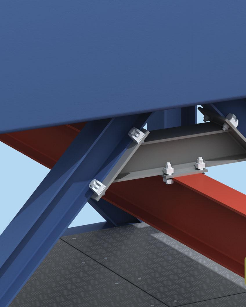
9 Steel Connections 1 Steel Connections Lindapter steel connections require no onsite drilling or welding, saving both time and money and are compatible with virtually any size/shape of steel section, in a wide variety of applications. The Girder Clamp symbolizes Lindapter s concept perfectly; boldly challenging the need to drill or weld, when a safe, high strength connection can be quickly accomplished by clamping two steel sections together. Although the concept is simple, Lindapter products undergo complex design and testing as the experienced Research & Development team constantly refine, improve and invent to achieve greater product performance and safety approvals. The connections shown throughout this catalog are actual applications from real project successes, both new construction and the refurbishment of existing structures. Advantages Less design time (Lindapter will design the connection) Independently approved loads and quality standards No onsite drilling or welding Fast and safe construction Hot Working not required Adjustable onsite Less work at height Onlyhandtoolsrequiredtoinstall Power not required Ability to deconstruct and multi-cycle Markets include: Plant Engineering Chemical and Petro-chemical Material Handling Structural Engineering Civil Engineering Facades Theatre Equipment Transportation Offshore Applications include: Steel Construction Cranes Lifting Beams Pipe Supports Towers and Masts Almost any steel-to-steel connection 9

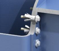
10 Girder Clamps Steel Connections 1 Components of a Girder Clamp 1. Standard Grade 5 Hex Nut 2. Standard Hardened Washer 3. Lindapter Clamp Dependent on the application different clamps could be used, i.e. TypesA,B,BR,AF,LR,LS. 4. Packing Piece In combination with the clamps mentioned above, these parts increase the tail length to enable the product to sit correctly on the beam. 5. Location Plate (can be supplied if required) This is an essential part of the girder clamp assembly that enables all the components to be located in the correct position. The hole centers and plate thickness are calculated to suit the individual application. 6. Lindapter Clamp This can be of a similar type as 3 (above), although certain products are designed to specifically work together, i.e. A + B. 7. Standard SAE Grade 5 Hex Bolt or Setscrew Loads The table below shows tensile and frictional load capabilities for a standard four bolt Girder Clamp using 4 bolts and 8 clamps at a 90 crossover angle. Lindapter is only too pleased to carry out design work for individual connections free of charge based on the following details: Load per connection Size and type of both beams Angle of crossover Distance between beams Inclination of beams 6 7 Clamps Types A, B, BR, LR Type AF Bolt size 1/2" 5/8" 3/4" 1" 1" 1" Bolt grade Grd. 5 Grd. 5 Grd. 5 Grd. 5 Grd. 5 A490 Tensile / for 4 bolts lbs ) Friction / for 4 bolts lbs ) ) Torque ft lb ) Factor of safety 3.2:1 2) Factor of safety 2:1 Loads are based on a factor of safety (typically 5:1). The reduction of published safety factors is not recommended. Approvals All approvals apply to Girder Clamps using types A and B only, in sizes from 1/2" to 1". Further information is available upon request. 10 inquiries@lindapterusa.com

 = 3-3/4\" Next standard bolt length = 4\" Correct installation of types A and B showing type A as an example Parallel")

11 Bolt Length / Tail Length / Installation Steel Connections 1 Bolt length calculation for a standard Lindapter Girder Clamp, example shows Type A and B 3 /4" Tail length The different tail length can be identified by a code of dimples underneath the clamps. To calculate the bolt length, all parts the bolt will go through have to be added up. The next longer standard bolt length should be used. 0.5 boltø as bolt protrusion 3/8" One dimple: tail length short (s) Height of nut 3/4" + Washer 1/8" + T of top clamp + Top section 3/4" 1/2" Two dimples: tail length medium (m) + Plate thickness 1/2" + Lower section 3/8" + T of lower clamp 3/8" Three dimples: tail length long (l ) = 3-3/4" Next standard bolt length = 4" Correct installation of types A and B showing type A as an example Parallel flanges 90º <90º >90º Maximum tail length tolerance of 3 / 64" (upto 5 / 8") and 1 / 16" ( 3 / 4", 1") before applying the torque is acceptable. Tapered flanges 90º <_5º 5-8º <90º On 6º and 8º slopes types A and B require a special tail length/packing combination which will allow the clamp to tilt back slightly (incorporated into the combination table on page 15). For applications above 8 please see types AF, LR and LS. inquiries@lindapterusa.com 11

12 Type A Steel Connections 1 Type A Malleable iron, bright zinc plated / hot dip galvanized Nose Recess Clamping Area K Skirt Tail T V Y X Typical Applications (see also pages 36-39) Type A clamp with recessed top to hold the bolt head captive while the nut is tightened. The skirt prevents the clamp rotating during installation. Suitable for parallel flanges, and tapered flanges up to 8. The clamp is installed correctly when the area K grips the flange. The tail must be chosen to suit the thickness of the flange being gripped. For correct tail length/packing combinations, please see page 15. Safe Working Loads Dimensions Product Grd. 5 (5:1 Factor of Safety) Tail Length V Code Bolt Size Tensile / 1 Bolt Frictional / 2 Bolts Torque Y X short medium long T Width lbs lbs ft lb LA037 3/8" /16" 7/16" 1/8" 3 /16" 1/4" 3/16" 1" LA050 1/2" " 1/2" 3/16" 1/4" 3/8" 1/4" 1-1 /8" LA062 5/8" /16" 5/8" 1/4" 5/16" 7/16" 5/16" 1-3/8" LA075 3/4" /16" 3/4" 5/16" 3/8" 1/2" 3/8" 1-13 /16" LA100 1" /8" 1" 3/8" 1/2" 5/8" 1/2" 2-1/8" For higher loads, the type AF should be used (see page 16). Order example: LA062M 12 inquiries@lindapterusa.com

13 Type B Steel Connections 1 Type B Malleable iron, bright zinc plated / hot dip galvanized Nose Flat Top Clamping Area K Skirt Tail T V Y X Type B clamp with flat top which allows the bolt head or nut to be rotated. Suitable for use with bolts, studs, tie rods, J-bolts, parallel flanges, and tapered flanges up to 8. The clamp is installed correctly when the area K grips the flange. The tail must be chosen to suit the thickness of the flange being gripped. For correct tail length/packing combinations, please see page 15. Typical Applications (see also page 36-39) Safe Working Loads Dimensions Product Grd. 5 (5:1 Factor of Safety) Tail Length V Code Bolt Size Tensile / 1 Bolt Frictional / 2 Bolts Torque Y X short medium long T Width lbs lbs ft lb LB037 3/8" /16" 7/16" 1/8" 3 /16" 1/4" 3/8" 1" LB050 1/2" " 1/2" 3/16" 1/4" 3/8" 1/2" 1-1 /8" LB062 5/8" /16" 5/8" 1/4" 5/16" 7/16" 5/8" 1-3/8" LB075 3/4" /16" 3/4" 5/16" 3/8" 1/2" 3/4" 1-13 /16" LB100 1" /8" 1" 3/8" 1/2" 5/8" 1" 2-1/8" For higher loads, the type AF should be used (see page 16). Order example: LB062M inquiries@lindapterusa.com 13
14 Accessories for Type A and B Steel Connections 1 Type CW - Clipped Washer Mild Steel, bright zinc plated / hot dip galvanized Y X T Product Bolt Dimensions Code Size Y X T Width LCW037 3/8" 3/16" 9/16" 1/16" 1" LCW050 1/2" 1/4" 3/4" 1/8" 1-1/4" LCW062 5/8" 5/16" 11/16" 1/8" 1-1/2" LCW075 3/4" 3/8" 7/8" 3/16" 1-3/4" LCW100 1" 1/2" 1-1/8" 3/16" 2-1/4" Packing used to adjust the tail length of the clamp to meet differing beam flange thicknesses. Order example: LCW062 Type P1 short / P2 short Mild Steel, malleable iron, bright zinc plated / hot dip galvanized Y X T P1 T P2 Product Code Bolt Dimensions P1 P2 Size Y X T P1 T P2 Width LP1037S LP2037S 3/8" 3/16" 1/2" 3/16" 3/8" 15/16" LP1050S LP2050S 1/2" 1/4" 5/8" 1/4" 1/2" 1-3/16" LP1062S LP2062S 5/8" 5/16" 13/16" 5/16" 5/8" 1-3/8" LP1075S LP2075S 3/4" 3/8" 15/16" 3/8" 3/4" 1-11 /16" LP1100S LP2100S 1" 1/2" 1-1/4" 1/2" 1" 2-1/8" Packing used to adjust the tail length of the clamp to meet differing beam flange thicknesses. Order example: LP1062S Type T Malleable iron, bright zinc plated / hot dip galvanized To fill the nose of type A and B, making it horizontal. For parallel flanges only. The thickness T should be added for tail length and bolt length calculations. The product is for aesthetic purposes only and technically not necessary. T Product Bolt Dimensions Code Size T LT050 1/2" 1/8" LT062 5/8" 3/16" LT075 3/4" 3/16" LT100 1" 1/4" Order example: LT062 Type W Mild Steel, malleable iron, bright zinc plated / hot dip galvanized Washer to fill the recess of type A to enable the nut to be tightened. When calculating the bolt length, please add T. T Product Bolt Dimensions Code Size T LW037 3/8" 3/16" LW050 1/2" 1/4" LW062 5/8" 5/16" LW075 3/4" 3/8" Order example: LW inquiries@lindapterusa.com
15 Plate and Packing Details for Type A and B Steel Connections 1 Location and End Plates L 1 l 1M b 1 L 1 l 1M b 1 L 1 = L 2 = l 1M, l 2M = b 1,b 2 = d = s = Plate length Plate width Hole centers Flange width Hole Ø Plate thickness d b 2 l 2M L 2 l2m d L2 Location Plate End Plate Plate Dimensions Material: Mild Steel Grade A36 (for other grades, please contact Lindapter) Location Plate End Plate 1) Plate Plate Bolt Hole Ø Thickness Hole Centers Length/Width Thickness Hole Center Length Hole Center Width d s l 1M, l 2M min L 1,minL 2 s l 1M min L 1 min l 2M min L 2 3/8" 7/16" 5/16" b + 7/16" b+1-3/4" 1/2" b 1 + 7/16" b /4" 2" l 2M +1-5/8" 1/2" 9/16" 3/8" b + 9 /16" b+2-1 /4" 1/2" b /16" b /4" 2-3 /8" l 2M +2" 5/8" 11/16" 3/8" b + 11 /16" b+2-3 /4" 5/8" b /16" b /4" 2-7 /8" l 2M +2-3 /8" 3/4" 13/16" 1/2" b + 13/16" b+3-1/4" 7/8" b /16" b /4" 3-5/8" l 2M +2-3/4" 1" 1-1 /8" 5/8" b+1-1 /8" b+4-1 /2" 1" b /8" b /2" 4-3 /8" l 2M +3-5 /8" 1) Depending on type of connection and associated end plate use, the thickness may need to be modified to comply with accepted local design codes. Calculation of bolt length see page 11 Tail Length / Packing Combinations for Types A, B For beams up to and including 5 slope Flange Types A, B Thickness 3/8" 1/2" 5/8" 3/4" 1" A,B CW P1S P2S A,B CW P1S P2S A,B CW P1S P2S A,B CW P1S P2S A,B CW P1S P2S 3/16" m s /4" s m s s /16" l m m s s /8" s l s m s /16" l m l s m /2" l s s l m /16" s l l m s /8" s 1-1 l m l l /16" l m l s s /4" s s 1-1 l s l /16" m m 1-1 l m l /8" l s m m s /16" s m m m m - 1-1" m s l s s /16" l m l s l /8" l 1-2 s s 2-1 m l /16" m l 1-1 m s /4" s 1-2 m s 1-1 l For thicker flanges, please contact Lindapter. s = short m = medium l =long P1S=P1short P2S=P2short = Type not applicable Type BR Tail Length / Packing Combinations see page 27. inquiries@lindapterusa.com 15
 High friction clamp with recessed top to hold bolt head captive while the nut is tightened.")
16 Type AF Steel Connections 1 Type AF SG iron, hot dip galvanised Without washer: For bolt grade 5 Recess Nose Skirt With washer Type AFW Tail Flat Top T V Y X With washer inverted Type AFW for bolt grade A325 or A490 with larger hexagons Typical Applications (see also page 39-39) High friction clamp with recessed top to hold bolt head captive while the nut is tightened. Can be combined with type CF. The skirt prevents the clamp rotating during installation. The tail of the AF spans across slotted holes. For flanges up to 10, ideal for S-beams. Washer type AFW available (see illustration). For correct tail length/packing combinations, please see page 19. The Type AF is compatible with Grade 5/A325 and A490 bolts, please refer to the table below for performance comparisons. Safe Working Loads (5:1) Factor of Safety (2:1) Dimensions Product Bolt Tensile / 1 Bolt Frictional 1) / 2 Bolts Tail Length V T Code Grade Painted Steel 2) Galv. Steel Torque Y X short medium Type AF Type AF with AFW Width lbs lbs lbs ft lb LAF050 1/2" Grd. 5/A /8" 1-1/16" 3/16" 1/2" 11/16" 7/8" 1-9/16" LAF062 5/8" Grd. 5/A /8" 1-1/2" 5/16" 9/16" 7/8" 1-1/16" 1-15/16" LAF075 3/4" Grd. 5/A /16" 1-9 /16" 3/8" 11/16" 1" 1-1 /4" 2-3 /16" LAF100 1" Grd. 5/A /8" 2-3/8" 9/16" 1-1/8" 1-1/4" 1-5/8" 3-1/4" LAF050 1/2" A /8" 1-1/16" 3/16" 1/2" 11/16" 7/8" 1-9/16" LAF062 5/8" A /8" 1-1/2" 5/16" 9/16" 7/8" 1-1/16" 1-15/16" LAF075 3/4" A /16" 1-9/16" 3/8" 11/16" 1" 1-1/4" 2-3/16" LAF100 1" A ) /8" 2-3/8" 9/16" 1-1/8" 1-1/4" 1-5/8" 3-1/4" 1) Frictional load figures are based on Type AF and Location plates in hot dip galvanized finish. Calculated against slip (movement exceeding 0.004" / 0.1mm) 2) Shot blast and painted steel 3) 3.2:1 factor of safety Order example: LAF050S 16 inquiries@lindapterusa.com

17 Type CF Steel Connections 1 Type CF SG iron, hot dip galvanized Nose Anti-rotation markings Legs Y X Y X min T max T V min t max t Typical Applications (see also page 36-39) High friction clamp which hooks over flanges of beams, angles and channels. Lindapter markings act as a unique anti-rotation device. Can be combined with all Lindapter Girder Clamp products including type AF. Safe Working Loads (5:1) Factor of Safety (2:1) Product Bolt Grd. 5 Tensile / 1 Bolt Frictional 1) / 2 Bolts Dimensions Code Painted Steel 2) Galv. Steel Torque Y X t T V Width lbs lbs lbs ft lb LCF050 1/2" /4" 9/16" 1/4" - 1 /2" 13/16" -1-1 /8" 1" 1-13 /16" LCF062 5/8" /4" 11/16" 5/16" -5/8" 1" - 1-1/4" 1-1/4" 2-3/16" LCF075 3/4" /16" 7/8" 3/8" -3/4" 1-3/16" -1-9/16" 1-3/4" 2-9/16" CF Combinations with other Lindapter Clamps lbs lbs lbs ft lb CF / A 3) 1/2" CF / A 3) 5/8" CF / A 3) 3/4" CF / AF 1/2" CF / AF 5/8" CF / AF 3/4" Order example: LCF050 1) Frictional load figures are based on type CF and location plate in HDG finish. Calculated against slip (movement exceeding 0.004" / 0.1mm) 2) Shot blast and painted steel 3) Also applies to type B, BR, LR inquiries@lindapterusa.com 17

18 Accessories for Type AF Steel Connections 1 Type AFCW Mild Steel, hot dip galvanized Product Bolt Size Dimensions Code Y X T Width LAF050CW 1/2" 1/4" 1-5/16" 1/16" 1-9/16" Y X T LAF062CW 5/8" 5/16" 1-9/16" 1/16" 2" LAF075CW 3/4" 3/8" 1-5/8" 1/16" 2-3/16" Order example: LAF050CW Packing used to adjust the tail length of the clamp to meet differing beam flange thicknesses; has a slight bend along its center line which flattens out during installation. Type AFP1 / AFP2 Mild Steel, hot dip galvanized Packing used to adjust the tail length of the clamp to meet differing beam flange thicknesses. Y X T Product Bolt Size Dimensions Code Y X T P1 T P2 Width AFP1 AFP2 LAF050P1 LAF050P2 1/2" 1/4" 1-5/16" 3/16" 3/8" 1-9/16" LAF062P1 LAF062P2 5/8" 5/16" 1-5 /8" 3/16" 3/8" 2" LAF075P1 LAF075P2 3/4" 3/8" 1-13 /16" 3/16" 3/8" 2-3 /16" LAF100P1 LAF100P2 1" 1/2" 2-7/8" 3/16" 3/8" 3-3/8" Order example: LAF050P1 Type AFW SG iron, malleable iron, mild steel, hot dip galvanized T Product Bolt Size Dimensions Code T mm LAF050W 1/2" 3/16" LAF062W 5/8" 3/16" LAF075W 3/4" 1/4" LAF100W 1" 3/8" Washer filling the recess of the type AF. Additionally, it features two projections which, when the AFW is inverted, will captivate the larger hexagons of A325 or A490 bolts ( 1 /2" to 3 /4"). LAF100W (1" version) has no projections. T Order example: LAF050W 18 inquiries@lindapterusa.com
19 Plate and Packing Details for Type AF and CF Steel Connections 1 Location and End Plates L 1 l 1M b 1 L 1 l 1M b 1 L 1 = L 2 = l 1M, l 2M = b 1,b 2 = d = s = Plate length Plate width Hole centers Flange width Hole Ø Plate thickness d b 2 l 2M L 2 l2m d L2 Location Plate Plate Dimensions Material: Mild Steel Grade A50 (for other grades, please contact Lindapter) End Plate Location Plate End Plate 1) Plate Plate Bolt Hole Ø Thickness Hole Centers Length/Width Thickness Hole Center Length Hole Center Width d s l 1M, l 2M min L 1,minL 2 s l 1M min L 1 min l 2M min L 2 1/2" 9/16" 1/2" b + 9 /16" b+4" 5/8" b /16" b+4" 3-1 /8" l 2M +3-1 /8" 5/8" 11/16" 5/8" b + 11/16" b+4" 1" b /16" b 1 +4" 4" l 2M +4" 3/4" 13/16" 3/4" b + 13/16" b+5" 1-1/4" b /16" b 1 +5" 7" l 2M +7" 1" 1-1/8" 1" b+1-1/8" b+7" 1-5/8" b /8" b 1 +7" 7-7/8" l 2M +7-7/8" 1) Depending on type of connection and associated end plate use, the thickness may need to be modified to comply with accepted local design codes. 2) For combinations of Type CF with A, B and BR, see page 15 and for Type LR, see page 23. Calculation of bolt length see page 11 Tail Length / Packing Combinations for Type AF For beams up to and including 5 slope Flange Types AF Thickness 1/2" 5/8" 3/4" 1" AF AFCW AFP1 AFP2 AF AFCW AFP1 AFP2 AF AFCW AFP1 AFP2 AF AFCW AFP1 AFP2 3/16" s /4" s /16" s s /8" s s s /16" s s s /2" m s s s /16" m m s s /8" s m s s /16" m m m s /4" s 2-1 m m s /16" s m s s - 1-7/8" m m m s /16" m 1-1 m m s " s m m s /16" s 1-2 m 1-1 m s /8" m 3-1 s m s /16" s m m 1-1 m /4" s m m 2-1 m /16" m s m m /8" s m m m /16" m 2-2 m 1-2 m m /2" m s m m /16" m m m 1-2 m /8" m m m 1-2 m /16" m s m m /4" m 1-3 m m m /16" s s 4-3 s 3-3 m /8" s 1-4 m 1-3 m m /16" m m 2-3 s m " s m 3-3 s m s = short m = medium = Type not applicable inquiries@lindapterusa.com 19
 Self adjusting clamp for various flange thicknesses and slopes up to 15. The leg of the saddle prevents the clamp from rotating during installation. The LR tail spans slotted holes.")
 Clamping Range Dimensions Code Tensile / 1 Bolt Frictional / 2 Bolts Torque V Y X T Width with Saddle lbs lbs ft lb LLR037 3/8\" 330-15 1/8\" -3/8\" 13/16\" -15/16\"")
20 Type LR Steel Connections 1 Type LR Malleable iron, bright zinc plated / hot dip galvanized Nose Saddle Slot Leg Clip Tail max Y min X max T min V min Y max X min T max V Typical Applications (see also page 36-39) Self adjusting clamp for various flange thicknesses and slopes up to 15. The leg of the saddle prevents the clamp from rotating during installation. The LR tail spans slotted holes. For thicker flanges, packings P1 long and P2 long are available. For correct tail length/packing combinations, please see page 23. Safe Working Loads Product Grd. 5 Bolt Size (5:1 Factor of Safety) Clamping Range Dimensions Code Tensile / 1 Bolt Frictional / 2 Bolts Torque V Y X T Width with Saddle lbs lbs ft lb LLR037 3/8" /8" -3/8" 13/16" -15/16" 15/16" -1" 13/16" -15/16" 1-5/16" LLR050 1/2" /8" -1/2" 1"-1-1/8" 1"-1-1/4" 1"-1-1/8" 1-9/16" LLR062 5/8" /8" - 5 /8" 1-3 /16" -1-3 /8" 1-5 /16" -1-7 /16" 1-3 /16" -1-7 /16" 1-13 /16" LLR075 3/4" /8" -3/4" 1-5/8" -1-15/16" 1-13/16" - 2" 1-5/8" -1-7/8" 2-1/4" LLR100 1" /8" - 1" 1-7 /8" -2-1 /4" 2-1 /16" -2-1 /4" 1-3 /4" -2-1 /8" 3" Order example: LLR inquiries@lindapterusa.com


21 Type D2 / Type D3 Steel Connections 1 Type D2 Malleable iron, bright zinc plated, hot dip galvanised S Nose Recess T Clamping Area K Setscrew Tail Y X V Skirt Type D3 Malleable iron, bright zinc plated, hot dip galvanised Flat Top S T V Y X Adjustable clamps incorporate a setscrew to accommodate a wide range of flange thicknesses. Type D2 has a recessed head to hold the bolt head captive. The skirt prevents the clamp rotating during installation. For flanges up to 5. For thicker flanges packings P1 long and P2 long are available. For correct tail length/packing combinations please see page 23. Correct Installation: Setscrew S needs to be adjusted so that V is 1/32"mm shorter than the flange thickness prior to installation. Adjust the setscrew after installation so that the bolt is 90 to the clamp and the clamp contacts the flange with area K only. Typical Applications (see also page 36-39) Safe Working Loads Product Bolt Size (5:1 Factor of Safety) Clamping Range Dimensions Code Tensile / 1 Bolt Frictional / 2 Bolts Torque V 1) V 2) Y X S T Width lbs lbs ft lb LD2037 3/8" /8" 3/8" 13/16" 13/16" 3/16" 3/16" 1" LD2050 1/2" /8" 3/8" 1" 1" 3/16" 1/4" 1-1/8" LD2062 5/8" /16" 1/2" 1-3 /16" 1-3 /16" 1/4" 5/16" 1-3 /8" LD2075 3/4" /16" 11/16" 1-3/8" 1-3/8" 5/16" 3/8" 1-5/8" LD2100 1" /16" 3/4" 1-7/8" 1-15/16" 3/8" 1/2" 2-1/8" LD3050 1/2" /8" 3/8" 1" 1" 3/16" 1/2" 1-1/8" LD3062 5/8" /16" 1/2" 1-3/16" 1-3/16" 1/4" 5/8" 1-3/8" 1) Setscrew S inserted from above. 2) Setscrew S inserted from below. Order example: LD2100 BP inquiries@lindapterusa.com 21

22 Accessories for Type LR, D2 and D3 Steel Connections 1 Type P1 long / P2 long Mild Steel, malleable iron, bright zinc plated / hot dip galvanized Packing used to adjust the tail length of the clamp to meet differing beam flange thicknesses. Y X T P1 T P2 Product Grd. 5 Bolt Size Dimensions Code Y X T P1 T P2 Width P1 P2 LP1037L LP2037L 3/8" 3 /16" 15/16" 3 /16" 3/8" 15/16" LP1050L LP2050L 1/2" 1/4" 1-1 /4" 1/4" 1/2" 1-3 /16" LP1062L LP2062L 5/8" 5/16" 1-9/16" 5/16" 5/8" 1-3/8" LP1075L LP2075L 3/4" 3/8" 1-7/8" 3/8" 3/4" 1-11/16" LP1100L LP2100L 1" 1/2" 2-1 /2" 1/2" 1" 2-1 /8" Order example: LP1037L Type T Malleable iron, bright zinc plated /hot dip galvanised To fill the nose of type D2 and D3 making it horizontal. For parallel flanges only. The thickness T should be added for tail length and bolt length calculations. The product is for aesthetic purposes only and technically not necessary. T Product Bolt Dimensions Code Size T LT050 1/2" 1/8" LT062 5/8" 3/16" LT075 3/4" 3/16" LT100 1" 1/4" Order example: LT062 Type W Mild Steel, malleable iron, bright zinc plated / hot dip galvanised Washer to fill the recess of type D2 to enable the nut to be tightened. When calculating the bolt length please add T. T Product Bolt Dimensions Code Size T LW037 3/8" 3/16" LW050 1/2" 1/4" LW062 5/8" 5/16" LW075 3/4" 3/8" Order example: LW inquiries@lindapterusa.com
23 Plate and Packing Details for Type LR, D2 and D3 Steel Connections 1 Location and End Plates L 1 l 1M b 1 L 1 l 1M b 1 L 1 = L 2 = l 1M, l 2M = b 1,b 2 = d = s = Plate length Plate width Hole centers Flange width Hole Ø Plate thickness d b 2 l 2M L 2 l2m d L2 Plate Dimensions Location Plate Material: Mild Steel Grade A36 (for other grades please contact Lindapter) End Plate Location Plate End Plate 1) Plate Plate Bolt Hole Ø Thickness Hole Centers Length/Width Thickness Hole Center Length Hole Center Width d s l 1M, l 2M min L 1,minL 2 s l 1M min L 1 min l 2M min L 2 3/8" 7/16" 1/2" b + 7/16" b + 2-5/8" 5/8" b + 7/16" b+2-5/8" 2-3/4" l 2M +2" 1/2" 9/16" 1/2" b + 9 /16" b /8" 5/8" b + 9 /16" b+3-3 /8" 3-1 /8" l 2M +2-3 /8" 5/8" 11/16" 5/8" b + 11 /16" b /8" 3/4" b + 11 /16" b+4-1 /8" 4" l 2M +2-3 /4" 3/4" 13/16" 3/4" b + 13 /16" b /8" 1" b + 13 /16" b+4-7 /8" 4-3 /4" l 2M +3-1 /2" 1" 1-1 /8" 1" b+1-1 /8" b /4" 1-1 /4" b+1-1 /8" b+6-3 /4" 6" l 2M +4-1 /4" 1) Dependant on the use of the end plate the thickness might need to be increased. Calculation of bolt length see page 11 Tail Length / Packing Combinations for Type LR For beams up to and including 5 slope Flange Types LR Thickness 3/8" 1/2" 5/8" 3/4" 1" P1L P2L P1L P2L P1L P2L P1L P2L P1L P2L 3/16" /4" /16" /8" /16" /2" /16" /8" /16" /4" /16" /8" /16" " /16" /8" /16" /4" Tail Length / Packing Combinations for Type D2 and D3 For beams up to and including 5 slope Flange Types D2 and D3 Thickness 3/8" 1/2" 5/8" 3/4" 1" P1L P2L P1L P2L P1L P2L P1L P2L P1L P2L 7/8" /16" " /16" /8" /16" /4" For thicker flanges please contact Lindapter. P1L = P1 long P2L = P2 long inquiries@lindapterusa.com 23
 max V Self adjusting clamp for various flange thicknesses and slopes up to 10.")
24 Type LS Steel Connections 1 Type LS Cast Stainless Steel Grade 316 US Design Patent No: US D597,393 S. Nose Tail min Y max X max T min V max Y min X min T Typical Applications (see also page 36-39) max V Self adjusting clamp for various flange thicknesses and slopes up to 10. The special serrations on the tail prevent the clamp rotating during installation. The LS tail spans over slotted holes. For thicker flanges, packings LSP2 are available. For correct tail length / packing combinations, please see page 25. Safe Working Load (5:1) Factor of Safety (2:1) Clamping Product Grd. 5 Bolt Size Range Dimensions Code Tensile / 1 Bolt Frictional 1) / 2 Bolts Torque V Y X T Width lbs lbs ft lb LLS037 3/8" /8" - 9 /16" 5/8" - 3 /4" 11/16" - 15 /16" 5/8" - 13 /16" 1-1 /2" LLS050 1/2" /8" -13/16" 5/8" -7/8" 11/16" -1-1/8" 5/8" -7/8" 1-9/16" LLS062 5/8" /8" -1" 7/8" - 1" 1-1/16" -1-7/16" 3/4" -1-1/8" 2-3/16" LLS075 3/4" /8" -1-3 /16" 15/16" -1-1 /4" 1" /8" 7/8" -1-1 /4" 2-3 /8" 1) Frictional loads calculated against slip (movement exceeding 0.004" / 0.1mm). Order example: LLS inquiries@lindapterusa.com
25 Accessories, Plate and Packing Details for Type LS Steel Connections 1 Type LSP2 Stainless Steel Grade 316 Product Grd. 5 Bolt Size Dimensions Code Y X T Width LLS037P2 3/8" 3/16" 1-1/8" 3/8" 1-9/16" Y X T LLS050P2 1/2" 1/4" 1-5 /16" 3/8" 1-9 /16" LLS062P2 5/8" 5/16" 1-9 /16" 3/8" 2" LLS075P2 3/4" 3/8" 1-5 /8" 3/8" 2-3 /16" Packing used to adjust the tail length of the clamp to meet differing beam flange thicknesses. Order example: LLS050P2 Location and End Plates L 1 l 1M b 1 L 1 l 1M b 1 L 1 = L 2 = l 1M, l 2M = b 1,b 2 = d = s = Plate length Plate width Hole centers Flange width Hole Ø Plate thickness d b 2 l 2M L 2 l2m d L2 Location Plate End Plate Plate Dimensions Material: ASTM 304 or 316 Stainless Steel Location Plate End Plate 1) Plate Plate Bolt Hole Ø Thickness Hole Centers Length/Width Thickness Hole Center Length Hole Center Width d s l 1M, l 2M min L 1,minL 2 s l 1M min L 1 min l 2M min L 2 3/8" 7/16" 1/2" b + 7 /16" b /4" 5/8" b + 7 /16" b+2-3 /4" 3-1 /8" l 2M +2-3 /8" 1/2" 9/16" 5/8" b + 9 /16" b /8" 3/4" b + 9 /16" b+3-1 /8" 3-1 /8" l 2M +2-3 /8" 5/8" 11/16" 7/8" b + 11/16" b+4" 1" b+11/16" b+4" 4-3/8" l 2M +3-1/8" 3/4" 13/16" 1" b + 13/16" b + 5-1/8" 1-1/4" b + 13/16" b+5-1/8" 4-3/4" l 2M +3-9/16" 1) Depending on type of connection and associated end plate use, the thickness may need to be modified to comply with accepted local design codes. Calculation of bolt length see page 11 Tail Length / Packing Combinations for Type LS For beams up to and including 5 slope Flange Type LS Thickness 3/8" 1/2" 5/8" 3/4" P2 P2 P2 P2 1/2" /16" /8" /16" /4" /16" /8" Flange Type LS Thickness 3/8" 1/2" 5/8" 3/4" P2 P2 P2 P2 15/16" " /16" /8" /16" /4" For thicker flanges, please contact Lindapter. P2 = LSP2 inquiries@lindapterusa.com 25


26 Type BR / Type RC Steel Connections 1 Type BR Malleable iron, bright zinc plated / hot dip galvanised Nose Flat Top Clamping Area K Skirt Tail Versatile clamp for steel beams or rails. The skirt prevents the clamp from rotating during installation. The BR tail spans slotted holes. Suitable for flanges up to 8. T Y X V Grd. 5 Safe Working Loads Dimensions Product Bolt Size (5:1 Factor of Safety) Tail Length V Code Tensile / 1 Bolt Frictional / 2 Bolts Torque Y X short medium T Width lbs lbs ft lb LBR050 1/2" " 1/2" 3/16" 1/4" 1/2" 1-1/8" LBR062 5/8" /16" 5/8" 1/4" 5/16" 5/8" 1-3/8" LBR075 3/4" /8" 3/4" 5/16" 3/8" 3/4" 1-5/8" LBR100 1" /8" 1" 3/8" 1/2" 1" 2-1 /8" Order example: LBR050S Type RC Forged steel, corrosion protection as required Nose Hole to suit 1/2" -1" Skirt Tail Grd. 5 Min. Safe Working Load 1) Product Bolt Size (5:1 Factor of Safety) Dimensions Code Tensile / 1 Bolt Torque Tail Length V X L H Width W lb ft lb RCS050 1/2" /8" 1/4" -1-1 /16" 3" 1-1 /8" 2" RCS062 5/8" /8" 3/8" - 1" 3" 1-1/8" 2" RCS075 3/4" /8" 7/16" -7/8" 3" 1-1/8" 2" RCS100 1" /8" 1/2" -3/4" 3" 1-1/8" 2" 1) The safe working load depends on the position of the bolt hole. The greater dimension X the lower the load. Order example: RCS050 HDG with dimension X = inch Special clamp to secure rails or steel beams of 3 /8" or greater. Packings are available for thicker flanges. The RC tail spans slotted holes. Suitable for flanges up to 5. The product will be drilled to suit hole size and position requirements of the application. X L W H V 26 inquiries@lindapterusa.com
27 Accessories and Packing Details for Type BR Steel Connections 1 Type CW - Clipped Washer Mild Steel, bright zinc plated / hot dip galvanised Packing used to adjust the tail length of the clamp to meet differing beam flange thicknesses. Y X T Product Bolt Dimensions Code Size Y X T Width LCW050 1/2" 1/4" 3/4" 1/8" 1-1 /4" LCW062 5/8" 5/16" 11/16" 1/8" 1-1/2" LCW075 3/4" 3/8" 7/8" 3/16" 1-3/4" LCW100 1" 1/2" 1-1/8" 3/16" 2-1/4" Order example: LCW050 BP Type P1 short / P2 short Mild Steel, malleable iron, bright zinc plated / hot dip galvanised Packing used to adjust the tail length of the clamp to meet differing beam flange thicknesses. For Type BR please see the following: T P1 T P2 Location and End Plates, page 15 Calculation of bolt length, page 11 Tail Length / Packing Combinations for Types BR For rails up to and including 8 slope Y X Product Code Bolt Dimensions P1 P2 Size Y X T P1 T P2 Width LP1050S LP2050S 1/2" 1/4" 5/8" 1/4" 1/2" 1-3 /16" LP1062S LP2062S 5/8" 5/16" 13/16" 5/16" 5/8" 1-3/8" LP1075S LP2075S 3/4" 3/8" 15/16" 3/8" 3/4" 1-11/16" LP1100S LP2100S 1" 1/2" 1-1/4" 1/2" 1" 2-1/8" Order example: LP1050S BP Flange Type BR Thickness 1/2" 5/8" 3/4" 1" BR CW P1S P2S BR CW P1S P2S BR CW P1S P2S BR CW P1S P2S 3/16" s /4" m s s /16" m m s /8" s s m s /16" m m s m /2" s s s m /16" m s m s /8" s m s m /16" m s s s /4" s 1-1 m s s /16" m 1-1 s m m /8" s m m s /16" m m m m - 1-1" s s 1-1 s s /16" m m 1-1 s s /8" s s 2-1 m m /16" m m 2-1 m s /4" s 1-2 m s 1-1 m For thicker flanges, please contact Lindapter. Type BR is only available with tail length short and medium. s = short m = medium P1S = P1 short P2S = P2 short = Type not applicable NB: The flange thickness refers to t 1. t 1 inquiries@lindapterusa.com 27
.")
28 Type HD Steel Connections 1 Type HD Malleable iron, SG iron, corrosion protection as requested Type HD Hard / Soft Clip Plug Leg Nose Skirt Type HD Spring Clip Elastomer Spring The Type HD rail clamps facilitate the precise alignment of rails by allowing a high degree of stepless lateral adjustability. Three variants are available (see opposite page). Technical Data Suitable for all rails with tapered flanges and crane speeds of up to 200ft/min. For wheel loads above 90,000 lbf or lateral loads higher than wheel loads please contact Lindapter. Grd. 5 Normal High Dimensions Product Clip Bolt Size Lateral Conditions Lateral Conditions Leg Stud Lateral Adjustm. Plate Width Distances Width Code Type SWL* Torque SWL* Torque V Length H max L min A X 2) Y 2) W lbs ft lb lbs ft lb LHD075H Hard 3/4" F - 5 /16" F +1-1 /2" ± 7 /16" B /8" 1-3 /16" 1-1 /16" 2-15 /16" LHD075 S Soft 3/4" F -3/16" F +1-9/16" ±7/16" B + 5-3/8" 1-3/16" 1-1/16" 2-15/16" LDHD7G Spring 3/4" F - 5 /16" F +1-9 /16" ± 7 /16" B /8" 1-3 /16" 1-1 /16" 2-7 /8" LHD075S Soft & Pad 3/4" F 1) F +1-3/4" ±7/16" B + 5-3/8" 1-3/16" 1-1/16" 2-15/16" LHD075G Spring & Pad 3/4" F -1/16" 1) F +1-3/4" ±7/16" B + 5-3/8" 1-3/16" 1-1/16" 2-7/8" LHD100H Hard 1" F -5/16" F +1-5/8" ±5/16" B + 5-1/8" 1-3/16" 1-1/16" 2-15/16" LHD100S Soft 1" F -3/16" F +1-11/16" ±5/16" B + 5-1/8" 1-3/16" 1-1/16" 2-15/16" LHD100G Spring 1" F -3/16" F +1-11/16" ±5/16" B + 5-1/8" 1-3/16" 1-1/16" 2-7/8" LHD100S Soft & Pad 1" F +1/16" 1) F +1-7/8" ±5/16" B + 5-1/8" 1-3/16" 1-1/16" 2-7/8" LHD100G Spring & Pad 1" F -1/16" 1) F +1-7/8" ±5/16" B + 5-1/8" 1-3/16" 1-1/16" 2-7/8" * Lateral Safe Working Load (4:1 Factor of Safety) 1) Based on 3 /16" thick resilient pad. 2) Based on plug set at 3 o clock position. NB: Leg length V for use with rail sections only with tapered base. For parallel sections please refer to Lindapter. Order example: LHD075H HDG for rail: 28 inquiries@lindapterusa.com

29 Type HD Steel Connections 1 Type HD Hard Clip Leg length V should be selected to clamp rail down tightly and allow no vertical rail movement. Not to be used when the rail is supported by a resilient pad. H F V Y X B A Type HD Soft Clip Leg length V should be selected to allow vertical rail movement caused by rail wave, whilst holding the rail in precise alignment laterally. Rail ends need to be fixed. H F V Y X B A Type HD Spring Clip The spring clip version incorporates an elastomer spring into the nose of the product, designed to provide some vertical restraint to the rail whilst still allowing the rail to lift with rail wave. The elastomer spring is manufactured from high density synthetic polymer which has a Shore A hardness of The spring is unaffected by salt water and most chemicals and has a high resistance to abrasion. H F V Y X B A Resilient Pad Both the spring and soft clips can be used with a resilient pad to decrease track running noise / structural vibration, level out irregular contact between surface and rail and to spread wheel load evenly over a wider area. Resilient Pad V Installation 1. Position clip on bolt or stud. Place the plug in 3 o clock position and tighten the nut. 2. Rotate the built in nut profile in a clockwise direction from the 3 o clock position to locate the clip against the rail and laterally adjust the rail if required. 3. Apply the recommended torque to the hexagon nut. W +L -L inquiries@lindapterusa.com 29


30 Type BSNT / Type BSLN Steel Connections 1 Type BSNT Malleable iron, bright zinc plated / hot dip galvanised Nose Flat Top Special clamp for installation of beams flange to flange. The location plate is substituted by a connecting frame made of steel flats equalling the flange thicknesses in height. The clamps are welded to this frame. T Y X Grd. 5 Safe Working Loads Product Bolt Size (5:1 Factor of Safety) Dimensions Code Tensile / 1 Bolt Torque Y X T Width lbs ft lb LBSNT050 1/2" " 1/2" 5/8" 1-1/8" LBSNT062 5/8" /16" 1/2" 3/4" 1-3 /8" LBSNT075 3/4" /16" 3/4" 1" 1-5/8" LBSNT100 1" /8" 1" 1-1/4" 2-1/8" Order example: LBSNT050 Type BSLN Malleable iron, bright zinc plated / hot dip galvanised Extended Nose Flat Top Skirt Tail T Special clamp designed with longer nose to extend the contact area with the steel section. For parallel flanges only. Can be used with types CW, P1 short, P2 short. K Y X V Grd. 5 Safe Working Load Dimensions Product Bolt Size (5:1 Factor of Safety) Tail Length Code Tensile / 1 Bolt Torque Y X V T Width lbs ft lb LBSLN050 1/2" /16" 5/8" 1/4" 11/16" 1-1 /8" LBSLN062 5/8" /4" 11/16" 7/16" 5/8" 1-1/4" 30 inquiries@lindapterusa.com


31 Type F9 / Type HW/HC Steel Connections 1 Type F9 Malleable iron, bright zinc plated / hot dip galvanized Nut Bolt Single Leg Jaws V W X T Double Leg V Flange Clamp for connecting parallel running steel sections with flanges of the same width. Can be used with bolts or alternatively with threaded rod. Not suitable for tapered flanges. Product Code Safe Working Loads with without Bolt Size (5:1 Factor of Safety) Dimensions Bolt Bolt Tensile / 1 Bolt Torque X W V T Width lbs ft lb min max LF9037WB LF9037NB 3/8" " 3/4" 1-11/16" 1/2" 3/4" 15/16" LF9050WB LF9050NB 1/2" /8" 1" 2-3 /8" 11/16" 15/16" 1-3 /16" LF9062WB LF9062NB 5/8" /16" 1-1/8" 2-3/4" 13/16" 1-1/8" 1-3/8" LF9075WB LF9075NB 3/4" " 1-1 /4" 3-1 /4" 1" 1-3 /8" 1-3 /4" LF9100WB LF9100NB 1" " 1-3 /4" 3-3 /4" 1-1 /2" 2-3 /16" 2-1 /2" Order example: LF9037WB Type HW/HC Malleable iron, bright zinc plated / hot dip galvanized X Hemispherical Washer W2 R W1 L Y Hemispherical Cup 10 For vertical suspension on angled surface of up to 10 swing either side of the vertical. The hemispherical washer (HW) can be used without the cup. Loads are subject to applications. Please contact Lindapter. Dimensions Product Code Rod Size Washer Cup Washer & Cup Washer Cup X W 1 Y W 2 R L LHW037 LHC037 3/8" 1" 1/2" 1-1 /4" 1/2" 1/2" 9/16" LHW050 LHC050 1/2" 1-1/8" 1/2" 1-3/8" 1/2" 9/16" 5/8" LHW062 LHC062 5/8" 1-3 /8" 5/8" 1-5 /8" 5/8" 11/16" 3/4" LHW075 LHC075 3/4" 1-3/4" 3/4" 2-1/8" 3/4" 7/8" 15/16" LHW100 LHC100 1" 2-1/4" 1" 2-5/8" 1" 1-1/8" 1-1/4" Order example: LHW037 + LHC037 inquiries@lindapterusa.com 31


32 Type SC / Type LP Steel Connections 1 Type SC / Type LP Corrosion Protection as required Custom built connections for specific application requirements, such as vertical loads, loads at an angle and rotation of up to 360. Typical applications are shown, other loads and designs are available. All loads subject to suitability of supporting section. Type SC Type SC Shackle Clamp with 4 Bolts Loading: up to 13kip Directions: vertical lift Angle: ± 10º Type LP4 Lifting Point with 4 Bolts Loading: up to 15kip Directions: 360º rotation Angle: 0-90º Type LP6 Lifting Point with 6 Bolts Loading: up to 22kip Directions: 360º rotation Angle: 0-90º 32 inquiries@lindapterusa.com

33 Type FC - Flush Clamp Steel Connections 1 Type FC - Flush Clamp Forged steel, bright zinc plated plus JS500 The Flush Clamp is a highly adjustable Girder Clamp System without the need of a location plate. Suitable for connecting beams of varying widths and thicknesses. Suitable for flanges up to 10 slope, ideal for S-beams. For convenience and ease of installation, the Flush Clamp features an innovative beam width selector allowing the installer to quickly adjust the clamp to the required setting (marked from 3 to 7 ). Teeth on the special bolt and special washer engage teeth on the body of the clamp, preventing movement. Special Safe Working Loads Product Bolt (5:1 Factor of Safety) Clamping Range Dimensions Code Size Tensile / 4 Bolts Frictional / 4 Bolts Torque Flange Thickness Flange Width 1) T B lbs lbs ft lb V b LFCM16 5/8" /16" -3/4" 3"-7" 7/8" -1-1/16" 12" 1) Depending on beam connection angles (see table below). Order example: LFCM16 Flat washer Special washer Half nut Nut Body max T min V min T max V Special Bolt max. b B Minimum Possible Beam Connection Angles Bottom Beam Top Beam Flange 3" 4" 5" 6" 7" Width 3" " " " " Angle inquiries@lindapterusa.com 33


34 Loads and Specifications Steel Connections 1 Loads and Specifications Lindapter steel connections are designed to suit the loading condition of each application, as defined below. Safe working loads published in this catalog are for SAE Grade 5 bolts unless otherwise stated. Should you require assistance in selecting the correct product for your needs, please contact Lindapter. Tensile Loading In tensile applications, the load transmits a force parallel to the center line of the bolt shank, hence applying a load to the contact point of the Lindapter. See product data tables for allowable tensile loads at varying bolt sizes. Combined Loads When the connections are subject to more than one load condition, the resulting forces must be calculated to determine the product and bolt sizes required. Please contact Lindapter with your application. Frictional Loading The force is applied at 90 to the bolt shank. The point at which slip occurs depends upon the condition and finish of the steel, the coating of the Lindapter and the grade of bolt used. Slip is defined as the constant load at which relative movement between clamped components exceeds inch (0.1mm). Compression Loading Force here is applied directly to the supporting section rather than the Lindapter products. If, however, there is a gap between the surfaces being connected, the buckling strength of the supporting fabrication must be considered. Shear Loading The Safe Working Load of the assembly is determined by the bolt grade and diameter as the force is resisted by the cross sectional area of the bolt shanks. It is recommended that referencebemadetothebolt manufacturers technical literature or the relevant structural steel design code to ascertain a Safe Working Load per bolt. Torque The recommended torque values stated in the product sections must be applied in order to achieve the stated Safe Working Loads. Any reduction in torques applied will lower the product Safe Working Load and is not recommended. 34 inquiries@lindapterusa.com
35 Technical Inquiry Steel Connections 1 Technical Inquiry A pdf version of this form is available from the Resources > Download section at Date... Company Full Name Position... Department... Address... City... State... ip... Phone... Fax Web Project Name / Reference: Your details may be shared with your nearest Lindapter distributor to ensure your inquiry is dealt with as quickly as possible Is your case comparable with an application in this catalog? If yes, please state page and illustration number (if applicable)... Ifno,pleaseenclosedrawingdetail Load per connection: Tensile... Frictional... Please state any special load conditions (vibration, etc.) StaticLoad... Dynamic Load Load Cycles Beam Type Flange Width Flange Thickness Cross-over Angle Top Beam Bottom Beam 4. Corrosionprotectionofbeams Numberofconnectionsrequired... inquiries@lindapterusa.com inquiries@lindapterusa.com 35


36 Typical Applications Steel Connections 1 A selection of connection examples are shown below, please visit the Lindapter website to view more applications. GC001-1 GC001-3 GC001-4 GC001-5 GC001-6 GC001-7 GC001-9 GC GC inquiries@lindapterusa.com


37 Typical Applications Steel Connections 1 A selection of connection examples are shown below, please visit the Lindapter website to view more applications. GC002-1 GC002-2 GC002-3 GC002-4 GC003-1 GC003-3 GC003-4 GC004-1 GC004-2 inquiries@lindapterusa.com 37


38 Typical Applications Steel Connections 1 A selection of connection examples are shown below, please visit the Lindapter website to view more applications. GC004-4 GC005-1 GC005-2 GC006-1 GC006-2 GC006-3 GC006-5 GC006-6 GC inquiries@lindapterusa.com


39 Typical Applications Steel Connections 1 A selection of connection examples are shown below, please visit the Lindapter website to view more applications. GC008-2 GC008-3 GC008-4 GC009-1 GC009-2 GC010-1 GC011-1 GC011-2 GC012-1 inquiries@lindapterusa.com 39


40 Hollow Section (HSS) Connections 2 Hollow Section (HSS) Connections The Hollo-Bolt and Lindibolt eliminate the need for conventional through-bolting or welding of hollow structural section (HSS) or any steel structure where access is only available from one side. In the late 1940 s, Lindapter revolutionized blind connections with the development of the original Lindibolt, for situations where access to both sides of the steel was restricted. Following the introduction and wide acceptance of HSS, the Hollo-Bolt was invented to suit virtually any type of hollow section, including square, rectangular, circular and oval profiles. As with all Lindapter products, the R&D department has continued to develop the range with the rapid expansion in diameters, lengths, finishes, and head types. Following comprehensive testing, The Steel Construction Institute (SCI) and British Constructional Steelwork Association (BCSA) recognise the Hollo-Bolt as a primary structural connection, in the design guide Joints in Steel Construction Simple Connections. The Hollo-Bolt is also approved by the Deutsches Institut für Bautechnik and TÜV NORD. Both the Lindibolt and Hollo-Bolt enable fast and safe construction and can be swiftly installed by simply inserting the product into pre-drilled holes, then tightening to the recommended torque using hand tools. Typical Hollo-Bolt applications include: Primary Connections Balconies Secondary Connections Towers and masts Bridges Staircases and handrails Cladding Glazing and roofs


 H L Hollo-Bolt : M16, M20 (5/8\", 3/4\") H L D d D d Typical Applications (see also page 45)")
 M8 - M16 (5/16\" - 5 /8\") M8 - M20 ( 5 /16\" - 3 /4\") M8 - M20 ( 5 /16\" - 3")
41 Type HB - Hollo-Bolt Hollow Section (HSS) Connections 2 Type HB - Hollo-Bolt Steel, bright zinc plated plus JS 500 Steel, hot dip galvanized Stainless Steel Grade 316 Collar Rubber Washer Sleeve Cone Suitable for hollow sections, tubes and where access is available from one side only. For corrosion protection, the Hollo-Bolt comes with additional JS500 protection as standard or hot dip galvanized. Sizes 5 /8" and 3 /4" have a patented collapse mechanism for optimized clamping force. Awarded the Design Council s Millennium Product status for innovation in the year Hollo-Bolt : M8, M10, M12 (5/16", 3/8", 1/2") H L Hollo-Bolt : M16, M20 (5/8", 3/4") H L D d D d Typical Applications (see also page 45) Rubber Washer W W Rubber Washer compressed / increased clamping force Across Flats A/F Head Variations 5/16" Flush Fit Countersunk (Head) Hexagonal Head Socket Head Cap Screw M8 - M12 ( 5 /16" - 1 /2") M8 - M16 (5/16" - 5 /8") M8 - M20 ( 5 /16" - 3 /4") M8 - M20 ( 5 /16" - 3 /4") Supplied to order Button Head Security M8 - M12 ( 5 /16" - 1 /2") Supplied to order inquiries@lindapterusa.com 41
 W min t Length Outer Ø H D A/F Tensile Single Shear L d ft lb lbs lbs LHBM08 #1 2\" 1/8\" - 7 /8\" - 1-3 /16\" LHBM08 #2 2-3/4\" 7/8\" -1-5/8\" - 1-15/16\" 9 /16\" 3 /16\" 7 /8\" 3/4\" 17 899 1124")

 Type HB (LHBM16 and LHBM20 only)")
42 Type HB - Hollo-Bolt Hollow Section (HSS) Connections 2 Type HB - Hollo-Bolt Product Bolt Clamping Outer Sleeve Collar Torque Safe Working Loads 2) Code Length Thickness Ply 1) Height Ø (5:1 Factor of Safety) W min t Length Outer Ø H D A/F Tensile Single Shear L d ft lb lbs lbs LHBM08 #1 2" 1/8" - 7 /8" /16" LHBM08 #2 2-3/4" 7/8" -1-5/8" /16" 9 /16" 3 /16" 7 /8" 3/4" LHBM08 #3 3-5/8" 1-5/8" -2-3/8" /16" LHBM10 #1 2-1/4" 1/8" - 7 /8" /16" LHBM10 #2 3" 7/8" -1-5 /8" /8" 3 /4" 1 /4" 1-1 /8" 15 /16" LHBM10 #3 3-5 /8" 1-5 /8" -2-3 /8" /8" LHBM12 #1 2-3/8" 1/8" -1" /8" LHBM12 #2 3-5/8" 1" /16" /4" 13 /16" 1 /4" 1-1 /4" 1-3 /16" LHBM12 # /4" 1-13 /16" -2-3 /4" /8" LHBM16 #1 3" 5/16" -1-1/8" 5/16" 1-5/8" LHBM16 #2 4" 1-1/8" -2" 5/16" 2-1/2" 1-1/16" 5 /16" 1-1/2" 1-3/8" LHBM16 #3 4-3/4" 2" /16" 5/16" 3-5/16" LHBM20 #1 3-5/8" 5/16" -1-5 /16" 5/16" 1-15 /16" LHBM20 #2 4-3/4" 1-5/16" -2-3/8" 5/16" 3" 1-5/16" 3 /8" 2" 1-13/16" LHBM20 #3 5-7/8" 2-3/8" -3-3/8" 5/16" 4" Order example: LHBM08#1 BP plus JS 500 1) Type HB (LHBM16 and LHBM20 only) require the thickness of the outer ply to be at least 5/16". If necessary, spacer washers should be used beneath the collar to increase the thickness to 5 /16". 2) The Hollo-Bolt can be used on a wide variety of steel hollow shape sections; safe working loads shown are based on use in A36 structural tube. The safe working loads, in both tension and shear, are applicable to the Hollo-Bolt only. Failure of the section, particularly on those with thin walls and a wide chord face, could occur at a lower figure and its strength should be checked by a qualified structural engineer. Joints in Steel Construction - Simple Connections The tables above state the SWL with a 5:1 factor of safety and should be used for secondary applications. For primary design, please consult the guide Joints in Steel Construction - Simple Connections. The guide provides design guidance for the use of Hollo-Bolt and gives essential information for structural connections for use in buildings designed by the Simple Method, i.e. braced frames where connections carry mainly shear or axial loads only. To obtain further details on the Simple Connections guide, please contact: The Steel Construction Institute Tel: +44 (0) Fax: +44 (0) Bolt Diameter, Hole and Edge Distances Type HB Published by SCI/BCSA Connections Group. Publication Number: P212 ISBN Lindapter is a member of SCI and BCSA Clearance Type Hole Ø Hole Distances Edge Distances min t d 1 min A min B B+C LHBM08 9 /16" 1-3 /8" 1/2" 11/16" d 1 d 1 LHBM10 3/4" 1-9/16" 9/16" 7/8" LHBM12 13/16" 2" 3/4" 1" LHBM16 1-1/16" 2-3/16" 13/16" 1-5/16" LHBM20 1-5/16" 2-3/4" 1" 1-5/16" A B C Installation Hollo-Bolt 1. Align pre-drilled fixture and steel. Insert Hollo-Bolt through fixture and steel. 2. Grip the Hollo-Bolt collar with an open ended wrench. 3. Usingatorquewrench, tighten the central bolt to the recommended torque. 42 inquiries@lindapterusa.com

 Code Length Thickness Ply A/F (5:1 Factor of Safety) W min t")

43 Type HBFF-Hollo Bolt Flush Fit Hollow Section (HSS) Connections 2 Type HBFF - Hollo-Bolt Flush Fit Steel, bright zinc plated plus JS 500 Stainless Steel Grade 316 Cone Sleeve L d The latest Hollo-Bolt creates immense opportunity for architectural design as the bolt is concealed within the steel with no protruding bolt head or collar. Installation is fast and simple using Lindapter's innovative installation nut (one included per box) allowing the Flush Fit to be installed without the requirement of specialist skills or equipment. Type HBFF - Hollo-Bolt Flush Fit W Installation Nut A/F Product Bolt Clamping Outer Sleeve Installation Nut Torque Safe Working Loads 1) Code Length Thickness Ply A/F (5:1 Factor of Safety) W min t Length Outer Ø Tensile Single Shear L d ft lb lbs lbs LHBM08FF #1 2" 3/8" -1-1/16" 5/16" 1-3/16" LHBM08FF #2 2-3/4" 1-1 /16" -1-3/4" 5/16" 2-1 /8" 9 /16" 3/4" LHBM08FF #3 3-5 /8" 1-3 /4" -2-1 /2" 5/16" 2-7 /8" LHBM10FF #1 2-3/8" 1/2" -1-1/16" 3/8" 1-3/16" LHBM10FF #2 3" 1-1 /16" -1-3/4" 3/8" 2-1 /8" 3 /4" 15 /16" LHBM10FF #3 3-5 /8" 1-3 /4" -2-1 /2" 5/16" 2-7 /8" LHBM12FF #1 2-3/8" 1/2" -1-3 /16" 3/8" 1-3 /8" LHBM12FF #2 3-1/8" 1-3 /16" -2-1/32" 3/8" 2-1 /2" 13 /16" 1-5 /16" LHBM12FF #3 4" 2-1 /32" -2-7 /8" 3/8" 3-3 /8" 1) The Hollo-Bolt Flush Fit can be used on a wide variety of steel hollow shape sections; safe working loads shown are based on use in A36 structural tube. The safe working loads, in both tension and shear, are applicable to the Hollo-Bolt Flush Fit only. Failure of the section, particularly on those with thin walls and a wide chord face, could occur at a lower figure and its strength should be checked by a qualified structural engineer. Order example: LHBM08FF#1 BP plus JS 500 Bolt Diameter, Hole and Edge Distances Type HBFF 90º d 2 Clearance Countersunk Type Hole Ø Ø Depth Hole Distances Edge Distances d 1 d 2 t 1 min A min B B+C LHBM08FF 9/16" 1-1/16" 1/4" 1-3/8" 1/2" 11/16" LHBM10FF 3/4" 1-1/4" 1/4" 1-9/16" 9/16" 7/8" LHBM12FF 13/16" 1-3 /8" 5/16" 2" 3/4" 1" min t t 1 d 1 d 1 A B C Installation Hollo-Bolt Flush Fit Installation nut 1. Align pre-drilled fixture and steel. Insert Hollo-Bolt through fixture and steel. 2. Apply installation nut and grip nut with an open ended adjustable wrench. 3. Using a torque wrench, tighten the central counter-sunk bolt to the recommended torque. inquiries@lindapterusa.com 43

 Length Ø Tensile Single Y d Shear W P lbs lbs LLB037 M10 (3/8\") 2-11/16\" 7/16\" 674 764 1/4\" -1-3/16\" 5/16\" -3/8\" LLB050 M12 (1/2\") 3-1/8\" 9/16\" 1124 1124 3/8\" -1-7/16\" 3/8\" -1/2\" LLB062 M16 (5/8\")")
 Torque Nut A/F Size Metric (US Equiv.")
44 Type LB2 - Lindibolt 2 Hollow Section (HSS) Connections 2 Type LB2 - Lindibolt 2 Steel, bright zinc plated (Stainless Steel Grade 316) Washer Main Body Setscrew Cone Locknut Nut D C W W F B A d Y P Self heading bolt suitable for connecting to hollow-sections, tubes and where access is available from one side only. The Lindibolt 2 uses a standard clearance hole. Product Lindibolt 2 Hole Safe Working Load 1) (Factor of Safety 5:1) Clamping Length Projection Code Size Metric (US Equiv.) Length Ø Tensile Single Y d Shear W P lbs lbs LLB037 M10 (3/8") 2-11/16" 7/16" /4" -1-3/16" 5/16" -3/8" LLB050 M12 (1/2") 3-1/8" 9/16" /8" -1-7/16" 3/8" -1/2" LLB062 M16 (5/8") 4-1/8" 11/16" /2" -1-7/8" 1/2" -5/8" LLB075 M20 ( 3 /4") 5" 13/16" /16" -2-3 /8" 9/16" - 13 /16" LLB100 M24 (1") 6-3/16" 1-1/16" /16" -2-7/8" 11/16" -1 MainBodyBandNutC&D SetscrewF Thread Product Lindibolt 2 Bolt Code Size Metric (US Equiv.) Torque Nut A/F Size Metric (US Equiv.) Torque Nut A/F ftlb ftlb LLB037 M10 (3/8") 15 11/16" M5 (3/16") 4 5/16" LLB050 M12 (1/2") 23 3/4" M6 (1/4") 8 3/8" LLB062 M16 ( 5 /8") 60 1" M8 ( 5 /16") 17 1/2" LLB075 M20 (3/4") /4" M10 (3/8") 33 11/16" LLB100 M24 (1") /16" M12 (1/2") 59 3/4" 1) The safe working loads, in both tension and shear, shown above are applicable to the Lindibolt 2 only. Failure of the section, particularly on those with thin walls and a wide chord face, could occur at a lower figure and its strength should be checked by a qualified structural engineer. Order example: LLB037 Installation 1. Set nut (C) at (W) plus projection (P). Tighten Locknut (D). 2. Align pre-drilled fixtures. Insert Lindibolt 2 through both fixtures, cone end first. 3. Hold nut (C) with adjustable wrench and tighten bolt (F). Loosen off locknut (D) and tighten nut (C). Secure by re-tightening locknut (D). 44 inquiries@lindapterusa.com
")


45 Typical Applications Hollow Section (HSS) Connections 2 A selection of connection examples are shown below, please visit the Lindapter website to view more applications. HB001 HB002 HB003 HB004 HB005 HB006 inquiries@lindapterusa.com 45


46 Concrete Decking Connections 3 Concrete Decking Connections Easy to install connections that allow building services, such as pipes or electrical cabling, to be suspended from pre-cast hollow core slabs or composite structural floor decking profiles. Advantages include: Speed of installation Cost effective Easeofuse No special tools required Adjustable and easily removable Approved safe working loads It is important that the Type VN and all other Lindapter composite decking connections are installed only when the slab has been poured and the concrete reaches full strength. 46 inquiries@lindapterusa.com
 as well as HSS,steel sheeting or purlins.")
 Subject to the strength of the concrete section. Order example: LTCM08 Installation LINDAPTER LINDAPTER LINDAPTER LINDAPTER 1. 2. 3. 4. 5. 6. LINDAPTER 1. Drill hole.")

47 Type TC / Type VN Concrete Decking Connections 3 Type TC - Toggle Clamp Steel Strip, bright zinc plated Nut (LTC M10 only) Toggle V T W The Toggle Clamp is designed for service suspension from pre-cast hollow core slabs (minimum depth of core 3 ) as well as HSS,steel sheeting or purlins. Safe Working Load 1) Product Drop Rod Hole (4:1 Factor of Safety) Dimensions Code Size Ø Tensile / 1 Rod Torque T W Width V lbs ft lb LTCM08 M8 7/8" /16" 5/8" 1/2" LTCM10 M10 1" /16" 11/16" 9/16" 1) Subject to the strength of the concrete section. Order example: LTCM08 Installation LINDAPTER LINDAPTER LINDAPTER LINDAPTER LINDAPTER 1. Drill hole. If toggle is to be used to support from pre-cast hollow core slab, ensure hole is central to hollow core. 2. Insert threaded rod through toggle, ensuring nut is flush with end of rod. 3. Align toggle parallel with rod so that nut engages into the retaining cavity. 4. Offer up the assembly, inserting the toggle body completely through the hole. 5. Shake rod so that toggle body locates horizontally across hole. Allow rod to drop down so that the nut locates in the seat in the toggle body. 6. Wind up rod to top of section as shown as high as possible. Secure the assembly with a nut and washer. Type VN - V-Nut Malleable iron, mild steel, bright zinc plated 1/2" The V-Nut fits the re-entrant channel of several composite floor deckings. 1" Installation /2" Safe Working Load Product Drop Rod (4:1 Factor of Safety) Code Size Tensile / 1 Rod Torque (UNC) lbs ft lb LVN025 1/4" LVN037 3/8" Screw VN onto threaded rod. 2. Insert VN and rod into re-entrant channel of decking. 3. Rotate both rod and VN through 90 so that tapered sides engage the sides of the channel. Order example: LVN025 inquiries@lindapterusa.com 47

, the American insurance organization globally recognized")
48 Pipe / Conduit Supports 4 Pipe / Conduit Supports Lindapter provides easy-to-install solutions for supporting building services from structural or secondary beams, including: the suspension of HVAC equipment, pipe work, fire protection/sprinkler systems, suspended ceilings and electrical equipment. The range of high quality connections are extremely adjustable, allowing the fast alignment of pipes etc. for a quick, cost effective installation. As with all Lindapter connections, safety is paramount and where appropriate, independent approvals include VDS and FM (Factory Mutual), the American insurance organization globally recognized throughout the fire protection industry. The FM APPROVED mark, which is backed by third party scientific research and testing, verifies that Lindapter products conform to the highest standards. Please note, for the installation of heavy duty pipe supports such those of the petrochemical industry, the steel connections in Section 1 of this catalog are more suitable. For more information, please contact Lindapter who will be pleased to design a connection to your specific requirement. 48 inquiries@lindapterusa.com

49 Type FLS Pipe / Conduit Supports 4 Type FLS High Grade Alloy Steel, bright zinc plated Setscrew Locknut Nut Basket T Swivel Unit W X U R 360º Y Flange clamp with swivel unit. For parallel and sloping flanges. Supplied with a high tensile setscrew for secure grip. Safe Working Load (4:1 Factor of Safety) Torque (ft lb) Product Thread Tensile/ 25º Tensile/> 25º to 45 Clamping Thickness Setscrew Setscrew Nut Dimensions Code Y lbs lbs W N R T U X Width LFLS037 3/8" /8" -11/16" M /16" 2-1/8" 2-1/4" 1-1/16" 11/16" Order example: LFLS037 Installation N M Approved Applications Locate FLS onto flange. 2. Ensuring lug on locknut locates into main body, tighten down setscrew () and then tighten upper locknut (N). 3. Install threaded rod by screwing into nut located in nut basket (S). Ensure full thread capture. 4. Secure assembly in nut basket (S) from beneath using a locknut (not supplied). S 25 General Applications Parallel Flanges only Ensure that the cup point setscrew always grips on the tapered side of the flange inquiries@lindapterusa.com 49

 Thickness screw screw nut Dimensions Clear Tapped Y Y Tensile W N T U X Width V lbs ftlb ftlb")
50 Type FL Pipe / Conduit Supports 4 Type FL Malleable iron, bright zinc plated Hexagon Head Setscrew Rear Hole (Tapped / Clear) Main Body T N V W U X Y Flange Clamp suitable for use with parallel or tapered flange beams, supplied with the back hole drilled or tapped. The type FL uses a hexagon head, high tensile cup point setscrew for secure grip. Can be used with type SW Swivel Unit (see page 51) when connecting to inclined sections. Safe Working Load Torque (4:1 Factor Clamping Set- Set- Lock- Product Code Hole Ø Thread of Safety) Thickness screw screw nut Dimensions Clear Tapped Y Y Tensile W N T U X Width V lbs ftlb ftlb LFL037C LFL037T 7/16" 3/8" 540 1/8" -3/4" M10 (3/8") /4" 1-9/16" 7/8" 7/8" LFL050C LFL050T 1/2" 1/2" 700 1/8" -7/8" M10 (3/8") " 1-13/16" 1-1/8" 1" Order example: LFL037C Installation 1. Slide FL onto beam flange and tighten setscrew to recommended torque. Guideline: tighten the setscrew finger tight and then apply a further quarter turn (90 ) with spanner. 2. Tighten the locknut (N) to the recommended torque. On tapered flanges, the cup point setscrew has to grip on the inside of the flange. 50 inquiries@lindapterusa.com

 Clamping Thickness Setscrew Setscrew Locknut Dimensions Code X & Y Tensile / in")
 3 3 1\" 1-7 /16\" 7/8\" Order example: LLC025 Type SW - Swivel")

51 Type LC / Type SW - Swivel Unit Pipe / Conduit Supports 4 Type LC Malleable iron, bright zinc plated Setscrew Locknut Main Body T N V W X U Installation see page 50 type FL Y Flange clamp with tapped holes in position X and Y to accept threaded rod or cable clips. For parallel or tapered flanges. Supplied with a high tensile cup point setscrew. Safe Working Load Torque Product Thread (4:1 Factor of Safety) Clamping Thickness Setscrew Setscrew Locknut Dimensions Code X & Y Tensile / in Pos. X Tensile / in Pos. Y W N T U Width V lbs lbs ft lb ft lb LLC025 1/4" /8" - 13 /16" M6 ( 1 /4") 3 3 1" 1-7 /16" 7/8" Order example: LLC025 Type SW - Swivel Unit High Grade Alloy Steel, bright zinc plated Type FL (supplied separately) R V U Swivel unit for applications on inclined beams. Can be used with type FL. Supplied complete with a high tensile M10 x 1-9 /16" setscrew and nut. Safe Working Load Dimensions Product Drop (4:1 Factor of Safety) Max. With Bolt Code Rod Tensile Inclination Rotation Torque U R Width V lbs ft lb LSW037 M10 ( 3 /8") /4" 1" 1-3 /8" Order example: LSW037 inquiries@lindapterusa.com 51


52 Type F3 / Type F3-BICC Pipe / Conduit Supports 4 Type F3 Malleable iron, hot dip galvanized Nut Single Leg Bolt Double Leg T R S V W V X A two part flange clamp with large clamping range. The bolt can be substituted with either drop rod or J bolts. Supplied with, or without bolt. For parallel flanges only. Product Code Safe Working Load Clamping With No Bolt/Thread (4:1 Factor of Safety) Thickness Dimensions Bolt Bolt Tensile / 1 bolt W Torque S T V X Width R lbs min max ft lb LF3037WB LF3037NB M /16" 1-3/16" 15 7/8" 5/16" 3/8" 1" 1-1/2" LF3050WB LF3050NB M /32" 1-9/16" /8" 3/8" 1/2" 1-3/8" 1-15/16" LF3062WB LF3062NB M /32" 2-3/16" /8" 1/2" 5/8" 1-13/16" 2-3/8" LF3075WB LF3075NB M /32" 2-3 /4" /4" 9/16" 3/4" 2-3 /16" 3" Order example: LF3037WB Type F3-BICC Malleable iron, hot dip galvanised T Y S V 1 W V 2 X A two part flange clamp which fixes claw type cable cleats directly beneath the flange. Suppliedwithbolt. For parallel flanges only. Safe Working Load Clamping Product Bolt (4:1 Factor of Safety) Thickness Thread Dimensions Code Tensile W Y Torque T V 1 V 2 X Width S lbs ft lb F3M10BICCA M /16" M /16" 3/8" 5/8" 1-3/16" 1-1/2" Order example: F3M10BICCA Y 52 inquiries@lindapterusa.com
 can be used without the cup. Loads are subject to applications. Please contact Lindapter.")

 Installation Code Purlins Rod Tensile Torque lbs ft lb 10 Kingspan 3/8\" 44 6 Multibeam2&3 10 Metsec 3/8\" 22-44 6 10 eta 3/8\" 53 6 1. 2. 3. Order example: L037 L037 with LSW037 inquiries@lindapterusa.")
53 Type HW / HC / Type 10 Pipe / Conduit Supports 4 Type HW/HC Malleable iron, bright zinc plated / hot dip galvanized X Hemispherical Washer W2 R W1 L Y Hemispherical Cup 10 For vertical suspension on angled surface of up to 10 swing either side of the vertical. The hemispherical washer (HW) can be used without the cup. Loads are subject to applications. Please contact Lindapter. Dimensions Product Code Rod Size Washer Cup Washer & Cup Washer Cup X W 1 Y W 2 R L LHW037 LHC037 3/8" 1" 1/2" 1-1/4" 1/2" 1/2" 9/16" LHW050 LHC050 1/2" 1-1/8" 1/2" 1-3/8" 1/2" 9/16" 5/8" LHW062 LHC062 5/8" 1-3/8" 5/8" 1-5/8" 5/8" 11/16" 3/4" LHW075 LHC075 3/4" 1-3 /4" 3/4" 2-1 /8" 3/4" 7/8" 15/16" LHW100 LHC100 1" 2-1 /4" 1" 2-5 /8" 1" 1-1 /8" 1-1 /4" Order example: LHW037 + LHC037 Type 10 Mild steel - bright zinc plated A purlin clip to suit a large range of purlin sections. Can be used with type SW Swivel Unit (see page 51) for use on inclined purlins. Safe Working Load Product (3:1 Factor of Safety) Installation Code Purlins Rod Tensile Torque lbs ft lb 10 Kingspan 3/8" 44 6 Multibeam2&3 10 Metsec 3/8" eta 3/8" Order example: L037 L037 with LSW037 inquiries@lindapterusa.com 53

54 Steel Floor Connections 5 Steel Floor Connections Lindapter applied their connection concept to steel flooring and invented a range of innovative products making it possible to install checker plate or open bar grating without on-site drilling or welding, for a fast, low cost operation. Access to the underside of the flooring is not required, eliminating the need for costly scaffolding or elevated floors. Installation can be carried out quickly and safely from above, often by one person, significantly reducing installation costs. Both the Floorfast & Grate-Fast carry the Lloyds Register Type Approval in respect of their resistance to shock and vibration. Hot working is not required, creating particular benefits in hazardous environments such as petrochemical and processing industries, while a rapid and cost efficient installation is beneficial in any industry. 54 inquiries@lindapterusa.com


 Thickness Thickness Hole Ø BP HDG BP HDG Torque Key t d ft lb mm inches LFF031 M8 1/8\" -1/2\" 1/8\" -5/8\" 3/8\" 11/16\" - 3/16\" - 8 5 3 /16\" LFF037 M10 3/16\" - 1 /2\" 1/8\" - 5 /8\" 7/16\" 13/16\" 3/4\"")

55 Type FF - Floorfast Steel Floor Connections 5 Type FF - Floorfast Malleable iron, bright zinc plated / hot dip galvanized Stainless Steel Grade 316 Unique stepped clamping face Socket setscrew 90º 5/64" 13/16" t t 1 D d 2-3 /8" A - Nominal Clearance The product consists of a malleable iron body casting with a countersunk socket screw. The eccentric stepped web of the casting allows it to lock under the steel, providing full face contact when torque is applied. For thicker flanges, packing pieces can be supplied. Lloyds Register Type Approval for vibration resistance. ½ Flange Width 9 /16" Position of hole centers: ½ flange width - ½ A + 9 /16" Ferrule Countersunk D t 1 Product Floorplate Flange Countersunk Ø for Bolt Countersunk Depth for Bolt Hexagon Code Bolt 1) Thickness Thickness Hole Ø BP HDG BP HDG Torque Key t d ft lb mm inches LFF031 M8 1/8" -1/2" 1/8" -5/8" 3/8" 11/16" - 3/16" /16" LFF037 M10 3/16" - 1 /2" 1/8" - 5 /8" 7/16" 13/16" 3/4" 3/16" 3/16" /4" LFF050 M12 1/4" -1/2" 1/8" -5/8" 9/16" 1" 15/16" 1/4" 3/16" /16" 1) M10 and M12 hot dip galvanized versions a slotted countersunk screw is supplied. Order example: LFF050 Installation Pre-assemble Floorfast on underside of floorplate 3. with stepped surface facing inwards. 2. Align castings with straight edge parallel to the edge of the plate and hand tighten. 3. Lay floorplate into position 4. Using a hexagon key, release the countersunk screw one full turn. 5. Tighten down the countersunk socket screw. Removal Using a hexagon key, give the Type FF one full counterclockwise turn to release connection from the flange inquiries@lindapterusa.com 55


56 Type GF - Grate-Fast Steel Floor Connections 5 Type GF - Grate-Fast Body: Malleable iron, mechanical galvanized / hot dip galvanized Top Hat: Mild Steel, mechanical galvanized / hot dip galvanized Top Hat Bracket Socket Head Cap Screw T Cast Body Grating connection for rectangular open bar grating with cast main body giving superior clamping force. LGF031 with stainless steel top-hat bracket for GRP grating. LGF037 (OSB) with wider top-hat bracket for different grating sizes. LGF037 for use with 1-3/16" width floor grating bars only. Lloyds Register Type Approval for vibration resistance. LGF031 / LGF037 OSB W D W LGF037 D min X max X X Product Grating Bar Grating Bar Bar Body Hexagon Code Bolt 1) Flange Depth Width Distance Width Torque Key T D W X ft lb mm inches LGF031 M8 1/8" -3/4" 7/8" -1-1/2" 5/16" -3/8" 3/4" -1-7/8" 5/8" 4 6 1/4" LGF037 (OSB) M10 1/8" - 3 /4" 13/16" -1-3 /16" 1/8" - 1 /4" 1" /4" 3/4" 8 8 5/16" LGF037 M10 1/8" -3/4" 3/4" -1-1/4" 1/8" -1/4" 1-3/16" 3/4" 8 8 5/16" 1) M10 hot dip galvanized versions may be supplied with a hex head screw. Order example: LGF031 Installation 1. Position pre-assembled Grate-Fast with body between grating bars and nose pointing toward the steel. The arrows on the top hat bracket should also be pointing toward supporting steel and bracket itself resting on the bearing bars. 2. Slide Grate-Fast toward steel until nose fits under the beam flange. Where necessary, adjust body/screw to approximate flange thickness/grating depth Tighten cap screw. The Grate-Fast body will automatically rotate until it locks under the bearing bar, with the nose under the flange. Continue tightening to the recommended torque. 56 inquiries@lindapterusa.com
57 Section Details Appendix 6 C-Channel bf d tf C-Channels C-Channels C-Channels Beam Depth Flange Flange Edge Beam Depth Flange Flange Edge Beam Depth Flange Flange Edge Designation Width Thickness Designation Width Thickness Designation Width Thickness d bf tf d bf tf d bf tf C15 x 50 15" 3-1/16" 3/8" C9 x 20 9" 2-5/8" 1/4" C6 x 8.2 6" 1-7/8" 3/16" C15 x 40 15" 3-1 /2" 3/8" C9 x 15 9" 2-1 /2" 1/4" C5 x 9 5" 1-7 /8" 3/16" C15 x " 3-3/8" 3/8" C9 x " 2-3/8" 1/4" C5 x 6.7 5" 1-3/4" 3/16" C12 x 30 12" 3-3/16" 1/4" C8 x " 2-1/2" 3/16" C4 x " 1-3/4" 3/16" C12 x 25 12" 3-1/16" 5/16" C8 x " 2-3/8" 3/16" C4 x 5.4 4" 1-9/16" 1/8" C12 x " 2-15/16" 5/16" C8 x " 2-1/4" 1/4" C3 x 6 3" 1-5/8" 3/16" C10 x 30 10" 3-1 /16" 1/4" C7 x " 2-3 /16" 3/16" C3 x 5 3" 1-1 /2" 1/8" C10 x 25 10" 2-7/8" 1/4" C7 x 9.8 7" 2-1/16" 1/4" C3 x 4.1 3" 1-3/8" 1/8" C10 x 20 10" 2-3/4" 1/4" C6 x 13 6" 2-3/16" 3/16" C10 x " 2-5 /8" 1/4" C6 x " 2-1 /16" 1/4" S-Beam bf d tf S-Beams S-Beams S-Beams Beam Depth Flange Flange tf Beam Depth Flange Flange tf Beam Depth Flange Flange tf Designation Width to nearest Designation Width to nearest Designation Width to nearest d bf 1/16" d bf 1/16" d bf 1/16" S24 x /2" 8" 3/4" S15 x 50 15" 5-5/8" 3/8" S7 x " 3-5/8" 1/4" S24 x /2" 7-7/8" 3/4" S15 x " 5-1/2" 3/8" S6 x " 3-5/8" 3/16" S24 x " 7-1/4" 9/16" S12 x 50 12" 5-1/2" 7/16" S6 x " 3-3/8" 3/16" S24 x 90 24" 7-1/8" 9/16" S12 x " 5-1/4" 7/16" S5 x " 3-1/4" 3/16" S24 x 80 24" 7" 9/16" S12 x 35 12" 5-1 /8" 7/16" S5 x 10 5" 3" 3/16" S20 x /4" 7-1/4" 5/8" S12 x " 5" 5/16" S4 x 9.5 4" 2-3/4" 3/16" S20 x /4" 7" 5/8" S10 x 35 10" 5" 5/16" S4 x 7.7 4" 2-5/8" 3/16" S20 x 75 20" 6-3 /8" 1/2" S10 x " 4-5 /8" 5/16" S3 x 7.5 3" 2-1 /2" 1/8" S20 x 66 20" 6-1/4" 1/2" S8 x 23 8" 4-1/8" 1/4" S3 x 5.7 3" 2-3/8" 1/8" S18 x 70 18" 6-1/4" 7/16" S8 x " 4" 1/4" S18 x " 6" 7/16" S7 x 20 7" 3-7 /2" 1/4" inquiries@lindapterusa.com 57
58 Section Details Appendix 6 W-Beam bf d tf W-Beams W-Beams W-Beams Beam Depth Flange Flange Edge Beam Depth Flange Flange Edge Beam Depth Flange Flange Edge Designation Width Thickness Designation Width Thickness Designation Width Thickness d bf tf d bf tf d bf tf W44 x /4 1 3 /4 W36 x / /16 W24 x / /8 3 9 /16 W44 x / /8 1 9 /16 W33 x / /8 2 1 /16 W24 x / /4 3 W44 x /16 153/4 17/16 W33 x / /8 W24 x /2 131/2 21/2 W44 x / /4 1 1 /4 W33 x / /8 1 3 /4 W24 x / /4 2 1 /16 W40 x /4 3 1 /4 W33 x / /4 1 9 /16 W24 x / /8 1 7 /8 W40 x /16 167/16 23/4 W33 x /8 157/8 13/8 W24 x /8 13/4 W40 x / /4 2 3 /8 W33 x / /4 1 1 /4 W24 x / /16 W40 x /8 161/16 21/16 W33 x /8 153/4 11/8 W24 x / /16 W40 x / /8 1 3 /4 W33 x / /2 1 1 /4 W24 x / /4 1 5 /16 W40 x / /8 1 5 /8 W33 x / /8 1 1 /16 W24 x /4 W40 x /4 157/8 19/16 W33 x /4 111/2 15/16 W24 x /4 127/8 11/16 W40 x /8 153/4 17/16 W33 x /8 111/2 7/8 W24 x /2 127/8 15/16 W40 x /4 1 1 /4 W33 x / /2 3/4 W24 x / /4 7/8 W40 x / /4 1 1 /16 W30 x / /8 3 W24 x /4 3/4 W40 x /4 153/4 13/16 W30 x /4 155/8 27/16 W24 x /2 9 1 W40 x /16 125/8 215/16 W30 x /8 153/8 21/16 W24 x /4 91/8 7/4 W40 x / /8 2 1 /2 W30 x /4 1 7 /8 W24 x /8 9 3/4 W40 x / / /8 W30 x / /8 1 5 /8 W24 x /8 9 11/16 W40 x / /16 W30 x / /2 W24 x /4 9 9/16 W40 x /4 W30 x /8 1 5 /16 W24 x /4 7 9/16 W40 x / /8 1 9 /16 W30 x / /16 W24 x /8 7 1/2 W40 x / /4 1 7 /16 W30 x / /16 W21 x /8 1 5 /8 W40 x /4 1 1 /4 W30 x / /2 1 3 /16 W21 x / /2 1 1 /2 W40 x /8 113/4 1 W30 x /4 101/2 1 W21 x /2 123/8 13/8 W40 x /4 113/4 13/16 W30 x /8 101/2 15/16 W21 x /2 11/8 W36 x / /8 4 1 /2 W30 x /2 7/8 W21 x / /2 1 1 /16 W36 x /16 W30 x / /2 3/4 W21 x / /8 15/16 W36 x /2 175/8 39/16 W30 x /8 101/2 11/16 W21 x /2 123/8 7/8 W36 x /4 171/4 215/16 W30 x /2 103/8 9/16 W21 x /8 121/4 13/16 W36 x / /16 W27 x /2 151/4 39/16 W21 x /8 83/8 15/16 W36 x /4 167/8 23/16 W27 x / W21 x /8 83/8 13/16 W36 x /8 163/4 2 W27 x /8 145/8 21/2 W21 x /4 81/4 3/4 W36 x / /8 1 7 /8 W27 x / /2 2 1 /16 W21 x /8 8 1 /4 11/16 W36 x / / /16 W27 x /4 1 3 /4 W21 x /4 5/8 W36 x /2 165/8 19/16 W27 x /8 141/4 15/8 W21 x /2 5/8 W36 x /4 161/2 17/16 W27 x /8 141/8 11/2 W21 x /4 81/4 1/2 W36 x / /2 1 3 /8 W27 x / /16 W21 x /8 6 1 /2 1/2 W36 x / /2 1 1 /4 W27 x / /8 1 3 /16 W21 x /8 6 1 /2 7/16 W36 x /8 121/4 13/4 W27 x / /16 W18 x / /4 W36 x /8 121/8 19/16 W27 x / W18 x /8 117/8 21/2 W36 x /4 121/8 13/8 W27 x / /8 W18 x /2 113/4 25/16 W36 x / /8 1 1 /4 W27 x / /8 15/16 W18 x /8 2 1 /8 W36 x /8 121/8 13/16 W27 x / /6 W18 x /8 111/2 115/16 W36 x / /8 W27 x /8 10 3/4 W18 x /8 111/2 13/4 W36 x W27 x /4 10 5/8 W18 x /8 1 9 /16 W36 x / /16 58 inquiries@lindapterusa.com
59 Section Details Appendix 6 W-Beam bf d tf W-Beams W-Beams W-Beams Beam Depth Flange Flange Edge Beam Depth Flange Flange Edge Beam Depth Flange Flange Edge Designation Width Thickness Designation Width Thickness Designation Width Thickness d bf tf d bf tf d bf tf W18 x / /4 1 7 /16 W14 x /8 1 3 /16 W12 x /8 4 3/8 W18 x / /4 1 5 /16 W14 x / /2 1 1 /16 W12 x /4 W18 x /4 111/8 13/16 W14 x /8 143/4 1 W12 x /8 4 1/4 W18 x /4 1 1 /16 W14 x / /8 15/16 W10 x / /8 1 1 /4 W18 x / /4 15/16 W14 x / /8 7/8 W10 x / /8 1 1 /8 W18 x /8 111/8 7/8 W14 x /8 145/8 3/4 W10 x /8 101/4 1 W18 x /8 11 3/4 W14 x /2 11/16 W10 x / /4 7/8 W18 x / /16 W14 x /4 101/8 7/8 W10 x /8 101/8 3/4 W18 x /2 7 5 /8 13/16 W14 x / /8 13/16 W10 x / /8 11/16 W18 x /8 7 5 /8 3/4 W14 x /4 W10 x /8 10 5/8 W18 x /4 71/2 11/16 W14 x /8 10 5/8 W10 x /16 W18 x /8 71/2 5/8 W14 x /8 8 11/16 W10 x /8 8 5/8 W18 x /2 9/16 W14 x /4 8 5/8 W10 x /8 8 1/2 W18 x /8 W14 x /8 8 1/2 W10 x /4 8 7/16 W18 x /8 6 1/2 W14 x /8 63/4 1/2 W10 x /2 53/4 1/2 W18 x /4 6 7/16 W14 x /4 7/16 W10 x /8 53/4 7/16 W16 x /8 1 W14 x /8 6 3 /4 3/8 W10 x /8 5 3 /4 3/8 W16 x / /8 7/8 W14 x /8 5 7/16 W10 x /4 4 3/8 W16 x /2 101/4 3/4 W14 x /4 5 5/16 W10 x /8 4 5/16 W16 x / /4 11/16 W12 x / / /16 W10 x /4 W16 x /8 7 1 /8 11/16 W12 x / / /16 W10 x /8 4 3/16 W16 x /4 7 1 /8 5/8 W12 x / /8 2 1 /2 W8 x /4 15/16 W16 x /8 7 9/16 W12 x / /4 W8 x /4 8 1 /4 13/16 W16 x /2 W12 x /8 21/16 W8 x 48 81/2 81/8 11/16 W16 x /8 7 7/16 W12 x /4 123/4 17/8 W8 x 40 81/4 81/8 9/16 W16 x /8 5 1 /2 7/16 W12 x / /8 1 3 /4 W8 x /8 8 1/2 W16 x /4 5 1 /2 3/8 W12 x /8 1 9 /16 W8 x /16 W14 x /8 181/2 51/8 W12 x /4 121/2 13/8 W8 x /2 7/16 W14 x /8 177/8 415/16 W12 x /8 123/8 11/4 W8 x 24 77/8 61/2 3/8 W14 x /8 175/8 41/2 W12 x /8 123/8 11/8 W8 x 21 81/4 51/4 3/8 W14 x /8 173/8 43/16 W12 x /8 121/4 1 W8 x 18 81/8 51/4 5/16 W14 x /4 171/4 313/16 W12 x /4 121/8 7/8 W8 x 15 81/8 4 5/16 W14 x / /2 W12 x / /8 13/16 W8 x /4 W14 x /8 3 3 /16 W12 x / /8 3/4 W8 x /8 4 3/16 W14 x /8 163/4 31/16 W12 x / /16 W6 x 25 63/8 61/8 7/16 W14 x /4 165/8 27/8 W12 x /8 12 5/8 W6 x 20 61/4 6 3/8 W14 x / / /16 W12 x /4 10 5/8 W6 x /4 W14 x / /8 2 1 /2 W12 x /16 W6 x /4 4 3/8 W14 x /8 161/4 21/4 W12 x /4 81/8 5/8 W6 x /4 W14 x /4 161/8 21/16 W12 x /16 W6 x 9 57/8 4 3/16 W14 x / /8 W12 x /2 W5 x 19 51/8 5 7/16 W14 x /8 1 3 /4 W12 x /2 6 1 /2 1/2 W5 x /8 W14 x /4 153/4 19/16 W12 x /8 61/2 7/16 W4 x 13 41/8 4 3/8 W14 x /2 153/4 17/16 W12 x /4 61/2 3/8 W14 x / /8 1 5 /16 W12 x /4 4 7/16 inquiries@lindapterusa.com 59
60 General Inquiry Appendix 6 General Inquiry A pdf version of this form is available from the Resources > Download section at Date Company Full Name Position Department Address City State ip Phone Fax Web Your details may be shared with your nearest Lindapter distributor to ensure your inquiry is dealt with as quickly as possible. Please send me: Catalog Product samples (please specify below): CAD CD Other (please write below): Please contact me immediately. I have questions regarding: Lindapter would like to keep you informed about the latest developments which could be valuable for you. Yes, I would like to be updated on new developments. I am particularly interested in the following: inquiries@lindapterusa.com 60 inquiries@lindapterusa.com
61 Notes 61
62 Notes 62


63 Projects Appendix 6 Exxon Mobil Refinery, Baytown, Texas Image Courtesy of Inmagine New York Port Authority Bus Terminal, New York Image Courtesy of Roger Rowlett Hartsfield-Jackson Airport, Atlanta Image Courtesy of Hartsfield-Jackson Atlanta International Airport Kimmel Center for the Performing Arts, Philadelphia Image Courtesy of Bradley Maule Manhattan Bridge, New York Image Courtesy of Istockphoto Kimmel Center for the Performing Arts, Philadelphia Image Courtesy of Evelyn Taylor The Huntington's Rose Hills Foundation Conservatory for Botanical Science, California Target Field Ball Park, Minnesota inquiries@lindapterusa.com Image Courtesy of The Huntington Library, Art Collections, and Botanical Gardens Image Courtesy of Wayne Kryduba / Minnesota Twins 63

64 Global Headquarters: Lindsay House Brackenbeck Road Bradford BD7 2NF England T: +44 (0) F: +44 (0) E: Your Authorized Lindapter Distributor: LindUSFeb11
Technical Innovation in Steelwork Connections
 Technical Innovation in Steelwork Connections Established 1934 Lindapter - Technical Innovation in Steelwork Connections 2 For more than 75 years, Lindapter has earned a respected reputation as the inventor
Technical Innovation in Steelwork Connections
 Established 1934 Technical Innovation in Steelwork Connections 2 Introduction to Lindapter Welcome For over 80 years Lindapter has earned a respected reputation as the pioneer of designing and manufacturing
Available from. Established Technical Innovation in Steelwork Connections
 Established 1934 Technical Innovation in Steelwork Connections 2 Introduction to Lindapter Welcome For over 80 years Lindapter has earned a respected reputation as the pioneer in the design and manufacture
Steel Floor Connections
 Steel Floor Connections Pioneering high strength steel connections since 1934 2 Steel Floor Connections by Lindapter Welcome For over 80 years Lindapter has earned a respected reputation as the pioneer
Tel: +44 (0)
") 4 Lindapter s support fixing range offers a series of ideal solutions for all building services. This includes the suspension of HVAC equipment, pipe work, fire protection/sprinkler systems, suspended
4 Lindapter s support fixing range offers a series of ideal solutions for all building services. This includes the suspension of HVAC equipment, pipe work, fire protection/sprinkler systems, suspended
Hollo-Bolt. High Clamping Force (HCF) M8 M10 M12 M16 M20 JS500 Stainless Steel Sheraplex Hot Dip Galv.
 M8 M10 M12 M16 M20 JS500 Stainless Steel Sheraplex Hot Dip Galv.") Type HB - Hollo- Type HB - Hollo- Steel, bright zinc plated plus JS5 Steel, sheraplex Steel, hot dip galvanised (Hex Head only) Stainless Steel Grade 316 Hollo- Suitable for hollow sections, tubes and
Type HB - Hollo- Type HB - Hollo- Steel, bright zinc plated plus JS5 Steel, sheraplex Steel, hot dip galvanised (Hex Head only) Stainless Steel Grade 316 Hollo- Suitable for hollow sections, tubes and
Cone. Bolt. Rubber Washer. Rubber Washer. compressed / increased clamping force
 Type HB - Hollo-Bolt Cavity Fixings 2 Type HB - Hollo-Bolt Steel, bright zinc plated plus JS 500 Steel, hot dip galvanised Stainless Steel Grade 316 Collar Sleeve Cone Bolt Suitable for hollow sections,
The Original Expansion Bolt for Structural Steel. Hollo-Bolt
 The Original Expansion Bolt for Structural Steel Hollo-Bolt 2 WELCOME THE ORIGINAL EXPANSION BOLT FOR STRUCTURAL STEEL Lindapter, the steel connection specialists, invented the Hollo-Bolt as a fast, cost
Khathij Industrial Fasteners
 Dear Sir/Madam, Khathij Industrial Fasteners This is Saqubar Sadique representing 'KHATHIJ INDUSTRIAL FASTENERS' from Chennai, India. We 'Khathij industrial fasteners' like to introduce us as a Stockist
ALUMINUM PIPE GUIDERAIL 01/01/
 NOTES PIPE RAILING & POSTS: Structural Tube, Pipe and Bar shall be in accordance with ASTM B22 or ASTM B429, Alloy 606-T6. End Rail 90 bends and corner bends with maximum 4-0" post spacing, may be Alloy
STEEL PIPE GUIDERAIL 01/01/
 NOTES PIPE RAILING & POSTS: Pipe Rails and s shall be in accordance with ASTM A5 Grade B for standard weight pipe and ASTM A500 Grade B, C or D or ASTM A50 for structural tube. Bars for handrail supports
Hollo-Bolt. The Original Expansion Bolt for Structural Steel ALLFASTENERS. Your trusted Australian supplier. Available
 Available WWW.ALLFASTENERS.COM.AU ALLFASTENERS. The Original Expansion Bolt for Structural Steel Now marked Hollo-Bolt by 2 WELCOME Call 1800 255 349 THE ORIGINAL EXPANSION BOLT FOR STRUCTURAL STEEL Lindapter,
PENSTOCK VALVES. Performance through Excellence
 VALVES & MANUFACTURING (1988) LTD. PENSTOCK VALVES Performance through Excellence SLIDEGATES WEIR GATES STOP LOGS SLIDEGATES PRECISION FACE SEALING VALVES WEIR GATES STOP LOGS SLIDEGATES Actuation Installation
The Original Expansion Bolt for Structural Steel. Hollo-Bolt
 The Original Expansion Bolt for Structural Steel Now marked by 2 WELCOME THE ORIGINAL EXPANSION BOLT FOR STRUCTURAL STEEL Lindapter, the steelwork connection specialists, invented the as a fast, cost effective
Composite Decking Fixings 3
 Composite Decking Fixings 3 Composite Decking Fixings Lindapter composite decking fixings have all been designed in conjunction with the various decking manufacturers to ensure they fulfil the necessary
MEFA mounting accessories
 MEFA mounting accessories Mounting accessories Base plates Page 5/2 Double holder Page 5/4 Height-adjustable suspensions Page 5/5 Pendular bolt joints Page 5/6 Trapeze hanger Page 5/7 Threaded hooks, distance
Technical Innovation in Steelwork Connections
 Technical Innovation in Steelwork Connections Available from Established 1934 Lindapter - Technical Innovation in Steelwork Connections 2 For more than 75 years, Lindapter has earned a respected reputation
5-axis clamping system compact
 5-axis clamping system compact 395 5-axis clamping system compact Function We are setting standards with the new KIPP 5-axis clamping system compact in this field. The system was specifically designed
APPENDIX FENCE GENERAL NOTES
 APPENDIX FENCE GENERAL NOTES 1. Fabric: 9 gage, 2" mesh, knuckle top and bottom, placed on the outside of posts, single fabric width for the entire height. 2. All fencing to be standard galvanized finish.
Beam and Purlin Clamps Beam Clamps
 Metal Framing & Cable Tray Steel City Hangers, Clamps & Fasteners Beam and Purlin Clamps Beam Clamps Fits beam flanges to 2" Supports 4" and 8" threaded rod, S-hooks, electrical boxes, conduit and bridle
Adjustable Feet Castors Accessories for Floor Elements
 Adjustable Feet Castors Accessories for Floor Elements Products in this section Levelling Knuckle Feet Threaded spindles for infinite height adjustment Metal or plastic foot plate Knuckle Feet X Compatible
PART MATERIALS. Section Fencing Materials. Description
 PART 03000 - MATERIALS Section 03010 - Fencing Materials Description 03010.00 Scope - This section consists of the test requirements, specifications and tolerances for barbed wire, woven wire and chain
Precision Engineering & Reliability WIRE ROPE SUSPENSION SYSTEM
 Precision Engineering & Reliability WIRE ROPE SUSPENSION SYSTEM DobyGrip Wire with Loop Quick and easy fixing to purlins, beams etc by forming a choke knot. Reduces the installation time compared to conventional
connecting the world PDF compression, OCR, web optimization using a watermarked evaluation copy of CVISION PDFCompressor
 C O N S T R U C T I O N I W I N D E N E R G Y I T U N N E L L I N G I R A I L I O E M connecting the world the tunnelling market Tunnelling is a key facet of infrastructure development particularly where
BEST PRACTICE GUIDE. Socket Bases. Working with Concrete Slabs
 Working with Concrete Slabs When working with concrete slabs the barrier protection can be erected in three ways - with socket bases, adjustable slab edge brackets and multi slab clamps. Socket Bases 1
1. TOOLS + MATERIALS REQUIRED
 R INSTALLATION INSTRUCTIONS PRODUCT: BALDUR + ODEN CONFIGURATION: BI-PARTING DOOR MOUNT: TOP MOUNT Product is covered by U.S. patents. For more information visit www.krownlab.com. TOOLS + MATERIALS REQUIRED
SECTION METAL FABRICATIONS
 SECTION 05100 PART 1 - GENERAL 1.01 DESCRIPTION A. Section includes specifications for metal fabrications, including minimum requirements for fabricator, and galvanizing. 1.02 REFERENCE STANDARDS A. ASTM
SECTION CONCRETE ANCHORING. Display hidden notes to specifier. (Don't know how? Click Here)
") PART 1 GENERAL 1.1 SECTION INCLUDES SECTION 03 15 00 CONCRETE ANCHORING Display hidden notes to specifier. (Don't know how? Click Here) A. General purpose mechanical anchors for horizontal and vertical
PART 1 GENERAL 1.1 SECTION INCLUDES SECTION 03 15 00 CONCRETE ANCHORING Display hidden notes to specifier. (Don't know how? Click Here) A. General purpose mechanical anchors for horizontal and vertical
Design Guide for Hot Dip Galvanizing best practice for venting and draining
 Design Guide for Hot Dip Galvanizing best practice for venting and draining Contents Introduction 3 Handrails/ 25 Balustrades Importance 4 of Venting and Draining Purpose Safety Quality Aesthetics General
INSTALLATION MANUAL IOWA MOLD TOOLING CO., INC. BOX 189, GARNER, IA MANUAL PART NUMBER:
 PARTS-1 Model 24562/28562 Crane INSTALLATION MANUAL IOWA MOLD TOOLING CO., INC. BOX 189, GARNER, IA 50438-0189 641-923-3711 MANUAL PART NUMBER: 99903701 Iowa Mold Tooling Co., Inc. is an Oshkosh Truck
Leveling Feet, Base Plates and Casters
 Leveling Feet, Base Plates and Casters 77 Leveling Foot 1 1 Fastening to profile end Fastening in T-slot of profile For leveling tables and light equipment. Ratchet-type height adjustment requires no tools.
KEEP YOUR RESOURCE MOVING.
 LINER BOLTS KEEP YOUR RESOURCE MOVING. COLUMBUS McKINNON CORPORATION Leading the Industry Downtime in the grinding mill operation is caused by one of two things: regularly scheduled maintenance or unscheduled
PRODUCT: LOKI INSTALLATION INSTRUCTIONS. Product is covered by U.S. patents. For more information visit
 R INSTALLATION INSTRUCTIONS PRODUCT: LOKI CONFIGURATION: SINGLE DOOR MOUNT: GLASS MOUNT Product is covered by U.S. patents. For more information visit www.krownlab.com . TOOLS + MATERIALS REQUIRED TOOLS
DobyGrip Accessories. Wire with Loop. Wire with Closed M6 & *M8 Eye Bolt. Wire with Carabina
 Wire with Loop Quick and easy fixing to purlins, beams etc by forming a choke knot. Reduces the installation time compared to conventional methods of suspension. All wires are supplied including the DobyGrip
Tel / (USA & CANADA) /
 /") Tel.58.847 / 8.388.459 (USA & CANADA) / Email sales@msdiscounttool.com MULTIPURPOSE CLAMPS - USA SERIES 7: Lightweight and 4% stronger than C clamps. Floating jaws that always stay parallel. Designed to
Tel.58.847 / 8.388.459 (USA & CANADA) / Email sales@msdiscounttool.com MULTIPURPOSE CLAMPS - USA SERIES 7: Lightweight and 4% stronger than C clamps. Floating jaws that always stay parallel. Designed to
Products for fixing to Steelwork and Decking
 Products 8.0 Beam Clamp - Single Support 8.1 Universal Joint for any variable Angle Adjustment 8.2 Beam Clamp TCS for Header Rails 8.3 Beam Clip for Cross Support/ Dimensioning of Bolts 8.4 Beam Clip for
Clamping bolts Eccentrical cams clamping units
 2.3 Shaft Clamping bolts Eccentrical cams clamping units 2.9 2.8 2.7 2.6 2.5 2.4 2.3 2.2 2.1 2.3 Clamping bolts, Eccentrical cams, Shaft clamping units Page 641 2.3 Clamping bolts, Eccentrical cams, Shaft
Experience the Hi-Lite Advantage
 Experience the Hi-Lite Advantage 12K Aluminum Shoring System INTRODUCTION The 12K Shoring System is primarily a hand-set system. It can also be handled with a crane, and may also be used quite successfully
Fixings & Fastenings. Bright Zinc Plated, Galvanised & Stainless Steel. Lockinex. ea i, ea u i
 Fixings & Fastenings Bright Zinc Plated, Galvanised & Stainless Steel Lockinex ea i, ea u i INTRODUCTION The Lockinex Range of Fixings & Fastenings are manufactured in Bright Zinc Plate, Hot dipped galvanised
5/16" Flange nut. Bolt Keeper Plate (8" Sq. SYS.) (3) 1/2" x 3" Hex head connector zinc plated bolt w/ washers and nut. Anchor 3" sq. 7 Ga.
 (3) 1/2 x 3 Hex head connector zinc plated bolt w/ washers and nut. Anchor 3 sq. 7 Ga.") 2 1/2" x 2 1/2" x 10 Ga. 6" 5" 4" Variable Slipbase (8" Sq. SYS.) 5/16 Corner Bolt W/ nut 5/16" Flange nut Stub Insert (8" Sq. SYS.) Bolt Keeper Plate (8" Sq. SYS.) (3) 1/2" x 3" Hex head connector zinc
2 1/2" x 2 1/2" x 10 Ga. 6" 5" 4" Variable Slipbase (8" Sq. SYS.) 5/16 Corner Bolt W/ nut 5/16" Flange nut Stub Insert (8" Sq. SYS.) Bolt Keeper Plate (8" Sq. SYS.) (3) 1/2" x 3" Hex head connector zinc
Stargrip series 3000 Mechanical Joint Wedge Action Restraint for Ductile Iron Pipe
 Stargrip series 3000 Mechanical Joint Wedge Action Restraint for Ductile Iron Pipe INFORMATION The Stargrip Mechanical Joint Restraint System is a unique product with a proven design that provides an exceptional
Superstrut Stainless Steel Channels and Accessories
 In this section... Superstrut Stainless Steel Channels and Accessories Superstrut Stainless Steel Channels and Accessories Channels...46 Channel Fittings and Hardware...47 49 Clamps and Hangers...50 52
POWER-Skru Large Diameter Concrete Screw
 POWER-Skru Large Diameter Concrete Screw Description The POWER-Skru Large Diameter Concrete Screw is a highstrength screw anchor with self-tapping threads that offer a unique undercutting design for anchoring
MATERIAL COMBINATION NUMBER 2: Corrosive environment requiring harder, wear-resistant seating faces and resistance to dezincification.
 Cast Iron Slide Gates Spec Sheet General The contractor shall furnish and install the following cast iron slide gate assemblies as listed on the Gate Schedule and detailed on the manufacturer s drawings.
Installation Instructions
 Column & Beam Units with Debris Netting Installation Instructions Laminated Wood Systems, Inc. Seward, Nebraska 800-949-3526 2015 LWS, INC. AVR-NET INSTALL 05-12-16 AVR Installation Notes 1 Safety The
Copper Tubing Hangers Clevis Hangers. Copper Tubing Hangers
 Copper Tubing Hangers Clevis Hangers Copper Tubing Hangers Fig. CT-69 Adjustable Swivel Rug Fig. CT-138R Fig. CT-65 Fig. CT-109 Extension Split Light Weight Adjustable Clevis Fig. CT-99 & CT-99C Split
SIGNALS AND LIGHTING FIELD GUIDE
 CHAPTER 16 SIGNAL AND LIGHT POLES SIGNAL AND LIGHT POLES The standards and requirements for installing traffic control signal and light poles are presented in this chapter. 16.1 Traffic Control Signal
SYGEF Standard SYGEF Plus PVDF Flanges
 Installation Instructions 2009 Volume, Rev 02 PM451 SYGEF Standard SYGEF Plus PVDF Flanges Please read all instructions before attempting to install flanges. Introduction When to Use a Flange Flanges may
SECTION MASONRY ANCHORAGE AND REINFORCEMENT. Display hidden notes to specifier. (Don't know how? Click Here)
") PART 1 GENERAL 1.1 SECTION INCLUDES SECTION 04080 MASONRY ANCHORAGE AND REINFORCEMENT Display hidden notes to specifier. (Don't know how? Click Here) A. Post installed masonry anchors. B. Miscellaneous
PART 1 GENERAL 1.1 SECTION INCLUDES SECTION 04080 MASONRY ANCHORAGE AND REINFORCEMENT Display hidden notes to specifier. (Don't know how? Click Here) A. Post installed masonry anchors. B. Miscellaneous
1. ANSI/ASME Standard B , Square and Hex Bolts and Screws, Inch Series
 SECTION 31 66 13 HELICAL PILES AND HELICAL ANCHORS PART 1 - GENERAL 1.1 DESCRIPTION A. This work pertains to furnishing and installing Helical Piles and Bracket Assemblies shown in the Contract in accordance
AUXILIARY FRAMING AND ACCESSORIES
 CUSTOM CABINETS & RACKS STRUT AND ACCESSO- RIES JUNCTION KITS ANGLE AND BRACE KITS SPLICE KITS BRACE KITS INSTALLATION KITS WALL ANGLE KITS RUBBER END CAPS SUPPORT INSTALLATION AND SUPPORT KITS STANCHION
Superstrut. Metal Framing. Beam Clamps. Design Loads. Finishes and Special Materials
 Loads Where design loads are indicated, they provide for a safety factor of 3 in conformance with the merican Standard Code for Pressure Piping. For more information, see page 57 for Engineering Data and
CONTENTS TOOL LIST U P S I D E I N N O V A T I O N S, L L C RAMP AND STEP SYSTEM ASSEMBLY INSTRUCTIONS. Revised: June 2013
 U P S I D E I N N O V A T I O N S, L L C RAMP AND STEP SYSTEM ASSEMBLY INSTRUCTIONS TOOL LIST Required Tools: - Reciprocating Saw with Metal Cutting Blade - Drill - 7/16 Drill Bit for Metal Drilling -
PIPE/CONDUIT SUPPORTS
 PIPE/CONDUIT SUPPORTS Pipe/Conduit Clamps...102-105 Unicushion... 106 Pipe & Tubing (Cush-A-Clamp ) Clamps...107-110 Pipe Hangers... 111 Pipe Rollers...111-112 Pipe Brackets... 113 Reference Tables...114-120
Simotec. 13.i
 Products: Framo 80 13.0 Products: Framo 80 13.1 Products: Structural Elements 100/120 13.2 Products: Pipe Shoes 13.3 Framo 80: Beam Section and Screw 13.4 Framo 80: Cantilever Bracket and End Support STA
Clamping devices 521
 Clamping devices 521 522 Product overview Clamping devices Adjustable straps K0001 Hook clamps K0012 Goose-neck straps with long slot K0002 Page 526 Hook Clamps with collar K0013 Page 535 Equipped clamps
Installation Systems INSTALLATION SYSTEMS
 INSTALLATION SYSTEMS 230 MM Channel System MM Channel System Page 230-237 MQ Channel System MQ Channel System Page 237-248 MC Channel System MC Channel System Page 249 Accessories Beam Clamp MAB Page 249
GAGING AND INSPECTION
 Fixture Plates...75 Fixturing Towers...76 CMM Fixturing Kits... 77-78 Clamping Components... 79-80 Standoffs and Locators... 81-82 Magnetic Components... 83-84 Height Adjustment...84 Positioners...85 Clamp
HD installation guide
 JANUS INTERNATIONAL 1 866 562 2580 www.janusintl.c o m 1950 1950HD installation guide RIGHT DRIVE END SHOWN LH OPPOSITE LEFT TENSION END SHOWN RH OPPOSITE PUSH-UP OPERATION 1950 1950HD SHOWN A rolling
SWAY BRACE PIPE ATTACHMENT FIG. 010
 Function: Designed for bracing pipe against sway and seismic disturbance. The pipe attachment component of a sway brace system used in conjunction with a PHD Manufacturing structural attachment fitting,
CSS Central Mount System
 CSS-20 Installation Manual CSS-20 Safety Notifications Below are the installation instructions for the CSS-20-2 Long Span Beam Mounting System. Please read these safety notifications prior to beginning
Installation Instructions Universal Crossmember Kit - 60 Track Width BEFORE Measure Twice, Weld Once! II
 Installation Instructions Universal Crossmember Kit - 60 Track Width Please read these instructions completely BEFORE starting your installation. Remember the basic rule for a successful installation:
Detroit Speed, Inc. Heavy Duty Leaf Spring Pocket Kit X-Body P/N:
 Detroit Speed, Inc. Heavy Duty Leaf Spring Pocket Kit 1968-74 X-Body P/N: 040111 Thank you for purchasing the Detroit Speed Inc., Heavy Duty Leaf Spring Pocket Kit for your 1968-74 X-Body. The DSE Leaf
PEC-TA Cast-in Channels and Bolts. Certified German quality for high-end fixing solutions. Advantages of using PEC Cast-in Channels.
 Fixing Technology s and Bolts PEC Cast-in Channels are ideally suited for quick, reliable and cost-efficient fixing of different construction elements. The possibility of making simple and flexible adjustments
PUSH-PULL-PROPS. and accessories ROBUSTA-GAUKEL GMBH MOUNTING TECHNOLOGY &CO.KG
 PUSH-PULL-PROPS and accessories MOUNTING TECHNOLOGY ROBUSTA-GAUKEL GMBH &CO.KG MOUNTING TECHNOLOGY PUSH-PULL-PROPS AND ACCESSORIES INDEX General information...................... 3 Push-pull-prop Type
RAIL PANEL AT TRANSITION SECTION PLAN - POST DETAIL PLAN - TUBE SPLICE. Colorado Department of Transportation. Staff Bridge Branch
 Limits of pay length for Bridge RailType 10M (For post spacing, see Dwg. No. B ) B60610 (Use with B60610A) 8 min. 1 max. 8 min. 1 max. 10 0 Max. 10 0 Max. post spacing 10 0 Max. 2 5 Post 1 x 1 slotted
Mission Statement. State Steel strives to provide quality products and services at competitive
 Mission Statement State Steel strives to provide quality products and services at competitive prices. This commitment is demonstrated with several branch locations all offering large, diverse inventories
VACUSEAL MODEL 200. HOT TUB PRODUCTS 233 Carrington Road Bethany CT
 VACUSEAL MODEL 200 J G F G H L HOT TUB PRODUCTS 233 Carrington Road Bethany CT 06524 860-469-2580 www.vacusealcoverlift.com www.hottubproducts.com Made in USA H K E D C I A P B 10 9 8 7 6 5 4 3 2 1 0 SPAS
101B, 210X, ELM, VSTB Installation Manual
 101B, 210X, ELM, VSTB Installation Manual 99-16105-I001 Copyright 2010 by ALL rights reserved. Information in this document is subject to change without notice. Companies, names and data used in examples
Technologies, Inc. Installation Instructions for Anchors & Components. Rev PAGE 1 / 11
 Installation Instructions for Anchors & Components PAGE 1 / 11 GROUND ANCHOR INSTALLATION INSTRUCTIONS NOTE: 1) The tensioning bolt can be inserted in the head from either side. 2) In areas of severe cold
TENANT IMPROVEMENT 16 FEBRUARY WEST 27TH STREET, 4TH FLOOR 100% CD OWNER/BID ADD 1-03/08/2018
 SECTION 055000 - PART 1 - GENERAL 1.1 RELATED DOCUMENTS A. Drawings and general provisions of the Contract, including General and Supplementary Conditions and Division 01 Specification Sections, apply
Pole Mount Installation Manual
 Pole Mount Installation Manual Thank You for Choosing AIMS Power! 1. AIMS Power is a leading supplier of solar products, specializing in PV mounting systems. We ensure our products are manufactured to
CONTENTS. Hammerscrews White Zinc Plated 2 Hammerscrews Stainless Steel A Nylon Frame Anchors Yellow Zinc Plated 3 Nylon Plug 3
 C CONTENTS CONTENTS PAGE 1 HAMMERSCREWS Haerscrews White Zinc Plated 2 Haerscrews Stainless A2-304 2 2 NYLON FRAME ANCHOR Nylon Frame s Yellow Zinc Plated 3 Nylon Plug 3 3 WINDOW FRAME ANCHOR Window Frame
VACUSEAL MODEL 300 & 400
 VACUSEAL MODEL 300 & 400 G L HOT TUB PRODUCTS 2 Toelles Road, Suite 13 Wallingford, CT 06492 860-469-2580 www.hottubproducts.com J G F H H K E D C I A P B 10 9 8 7 6 5 4 3 2 1 0 0 1 Figure 1 2 3 4 SPAS
installation guide
 JANUS INTERNATIONAL 1 866 562 2580 w w w. j a n u s i n t l. c o m 2000 2500 3000 installation guide RIGHT DRIVE END SHOWN LH OPPOSITE LEFT TENSION END SHOWN RH OPPOSITE PUSH-UP OPERATION 2000 2500 3000
DIY Lowery Inspired Embroidery Floor Stand
 DIY Lowery Inspired Embroidery Floor Stand Below find the details on how to build your own embroidery floor stand. The Lowery Floor Stand inspired this design. Note using the following instructions will
CONTENTS CABLE MANAGEMENT AND
 CONTENTS CABLE MANAGEMENT SECTION 9 SECTION 9 CABLE MANAGEMENT AND ASSOCIATED PRODUCTS.................................91 PIN CLIPS H335B SERIES.......................................92 COPPER EARTH RODS.........................................92
1.1 RELATED DOCUMENTS
 SECTION 050505 -BEVEL RAIL ENDS PART 1- GENERAL 1.1 RELATED DOCUMENTS A. Drawings and general provisions of the contract, including General and Supplementary Conditions and Division 01 Specification Sections
1.1 SUMMARY. A. This Section includes the following: 1. Loose steel lintels. 2. Shelf angles. 3. Metal floor plate. 4. Pipe bollards.
 PART 1 - GENERAL 1.1 SUMMARY A. This Section includes the following: 1. Loose steel lintels. 2. Shelf angles. 3. Metal floor plate. 4. Pipe bollards. B. See Division 5 Section "Pipe and Tube Railings"
S-BT screw-in stainless steel and carbon steel threaded studs
 S-BT screw-in stainless steel and carbon steel threaded studs Product data Dimensions S-BT-MR M10/15 SN 6 S-BT-MR M10/15 SN 6 AL**) S-BT-MR W10/15 SN 6 S-BT-MR W10/15 SN 6 AL**) S-BT-MR M10/15 SN 5 ***)
No. 412, 414, 416 Operations Manual
 No. 412, 414, 416 Operations Manual CARE: Occasional oiling of moving parts with machine oil will ease operation and extend the life of the brake. Occasionally check and tighten the lower beam bracket
Installation Instructions TMW Antenna Tower Mount for 4ft (1.2m) Antennas.
 Antennas.") Description The following pages show the steps required to assembly and fit the antenna mount to a vertical tower pipe of diameter 48 to 115 mm (1.9 to 4.5"). This mount provides ±20 azimuth or ±15 elevation
Description The following pages show the steps required to assembly and fit the antenna mount to a vertical tower pipe of diameter 48 to 115 mm (1.9 to 4.5"). This mount provides ±20 azimuth or ±15 elevation
Structural Bolting. Notice the Grade 5 has a much smaller head configuration and a shorter shank then the grade A325 structural bolt.
 Structural Bolting ASTM F3125/F3125M is a structural bolt specification covering inch and metric bolt grades. This specification contains 4 inch series bolting grades: A325, F1852, A490, and F2280. These
Pipe Restrainers series C Restrainers for use on IPEX Bionax AWWA CI OD C909 PVCO Pipe with MJ or Push-On Fittings
 Pipe Restrainers series 1000 1000C Restrainers for use on IPEX Bionax AWWA CI OD C909 PVCO Pipe with MJ or Push-On Fittings INFORMATION Restrainers for restraining mechanical joint or push-on fittings
Bumper Sign INSTALLATION INSTRUCTIONS
 Bumper Sign INSTALLATION INSTRUCTIONS BUMPERSIGN TOOL CHECKLIST SDS MAX Rotary Hammer Drill Marker/Pencil SDS MAX 1 Carbide Drill Bit Tape Measure Torque Wrench with ½ Drive Power Source Vacuum ½ Drive
Swifts cable ladder supports
 heavy duty cantilever arms Heavy duty cantilever arms enable horizontal runs of cable ladder to be mounted to vertical steel, concrete or masonry surfaces or to Swiftrack channel. They are suitable for
Lichtgitter Perforated Metal Planks
 Forge-welded gratings Pressure-locked gratings Perforated metal planks GRP gratings Chequer plates Spiral staircases Staircases Ladder rungs Steel Service Hot dip galvanising Lichtgitter Perforated Metal
Single and Double Gates Operation & Maintenance Manual
 R E L I A B L E S A F E A C C E S S Single and Double Gates Operation & Maintenance Manual System Overview SAFETY GATES KEE GATE is a complete range of safety gates designed specifically to provide permanent
TYPE J (20 FT - 40 FT) MICHIGAN DEPARTMENT OF TRANSPORTATION 10-0" 7-6" NOTE: sheet 5 & 6 of 10) DEPARTMENT DIRECTOR. Kirk T.
 MICHIGAN DEPARTMENT OF TRANSPORTATION 10-0 7-6 NOTE: sheet 5 & 6 of 10) DEPARTMENT DIRECTOR. Kirk T.") Column truss connection Chord splice (see details (See details sheets 3 & 4 of 10) s Top truss chord Free end panel 10-0" Support end panels length varies (See chart below) \ Truss Back truss chord Top
Column truss connection Chord splice (see details (See details sheets 3 & 4 of 10) s Top truss chord Free end panel 10-0" Support end panels length varies (See chart below) \ Truss Back truss chord Top
Kee Gate Operation & Maintenance Manual
 R E L I A B L E S A F E A C C E S S Kee Gate Operation & Maintenance Manual 2 Kee Gate System Overview KEE SAFETY S SAFETY GATES KEE GATE is a complete range of safety gates designed specifically to provide
Detroit Speed, Inc. Heavy Duty Leaf Spring Pocket Kit Camaro/Firebird P/N:
 Detroit Speed, Inc. Heavy Duty Leaf Spring Pocket Kit 1967-69 Camaro/Firebird P/N: 040110 Thank you for purchasing the Detroit Speed Inc., Heavy Duty Leaf Spring Pocket Kit for your 1967-69 Camaro/Firebird.
INTERPLANT STANDARD STEEL INDUSTRY CODE OF PRACTICE FOR CLAMPING OF CRANE RAILS
 INTERPLANT STANDARD STEEL INDUSTRY CODE OF PRACTICE FOR CLAMPING OF CRANE RAILS IPSS:1-8-17-14 (First Revision) Corresponding IS does not exist Formerly: IPSS:1-8-17-97. FOREWORD.1 This Interplant Standard
OUR QUALITY POLICY VISION MISSION
 AUSTENITE FASTENERS PVT.LTD. A unique name in fasteners line has come long way since its taking over Krishna Engineering Company which was established in 1999. The company has it is manufacturing plant
INVICTA PENSTOCK SOLUTIONS PENSTOCK SOLUTIONS
 INVICTA PENSTOCK SOLUTIONS PENSTOCK SOLUTIONS INVICTA PENSTOCK RANGE Invicta is a well established, service driven company offering complete valve, penstock and actuator solutions. Invicta Valves was formed
SYW Industry Sdn. Bhd. Stud Anchor. Hexagon Nut / Flange Nut. U - Bolt (c/w 2 Nuts) Steel Band. 1 of 8
 Steel Band. 1 of 8") SYW Industry Sdn. Bhd. Stud Anchor Hexagon Nut / Flange Nut U - Bolt (c/w 2 Nuts) Steel Band 1 of 8 BT Anchor (MM size) Expansion Anchor 2 of 8 Set Anchor Sleeve Anchor with Flange Nut 3 of 8 BT Anchor
SYW Industry Sdn. Bhd. Stud Anchor Hexagon Nut / Flange Nut U - Bolt (c/w 2 Nuts) Steel Band 1 of 8 BT Anchor (MM size) Expansion Anchor 2 of 8 Set Anchor Sleeve Anchor with Flange Nut 3 of 8 BT Anchor
International Tube & Conduit Company Ltd. BRITISH STANDARD STEEL CONDUITS & FITTINGS
 International Tube & Conduit Company Ltd. BRITISH STANDARD STEEL CONDUITS & FITTINGS 1 ABOUT THE COMPANY VISION STATEMENT We strive to exceed our customers expectations through leading edge technologies
MPA-9000 Universal Ceiling Projector Mount Kit
 I N S T R U C T I O N M A N U A L Universal Ceiling Projector Mount Kit The Universal Ceiling Projector Mount provides a unique, simplified method of ceiling mounting your inverted projector. This low
AVK High Strength Blind Threaded Fasteners. Ideal for blind applications
 High Strength Blind Threaded Fasteners Ideal for blind applications AVK Spinwall Technology How Hole Fill Works For You As the AVK insert is installed, the knurled body expands 360 to create hole fill.
Single and Double Gates Operation & Maintenance Manual
 R E L I A B L E S A F E A C C E S S Single and Double Gates Operation & Maintenance Manual 2 System Overview SAFETY GATES KEE GATE is a complete range of safety gates designed specifically to provide permanent
Midwest Roadside Safety Facility
 B 64" 1626 602'-8 1/16" 183695 548'-0" 167030 1 2 3 4 5 6 7 8 9 10 11 12 14 15 16 17 18 20 21 22 23 24 25 26 27 28 29 30 31 32 33 34 35 36 373839 40 25 IMPACT 1500A 48" 12 27'-5" 8355 [] 3x7 CL A Galvanized