Experience the Hi-Lite Advantage
|
|
|
- Dwayne Palmer
- 6 years ago
- Views:
Transcription

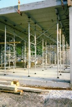
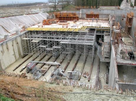


1 Experience the Hi-Lite Advantage 12K Aluminum Shoring System

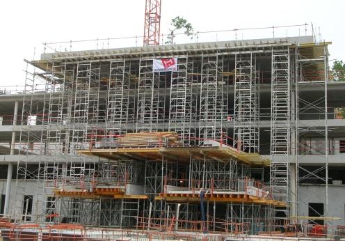
2 INTRODUCTION The 12K Shoring System is primarily a hand-set system. It can also be handled with a crane, and may also be used quite successfully as a rolling or a flying system. (Consult with Hi-Lite Engineering for design) Barry & Dave Jackson HI-LITE SYSTEMS 2

")

3 FEATURES & BENEFITS Hi-Lite Systems is the original manufacturer of the worlds very first aluminum shoring frames. As both the designer and the manufacturer of the system, we are naturally the best choice when it comes to supporting our customers, in all cases of design, layout and application of the product. 610mm (24in) Spacing Serrated Tread Hi-Lite s 12K Aluminum Shoring frames weigh less than half that of comparable capacity steel frames and they can be handled by a single worker. A 6ft high, 4ft wide 12K frame weighs 14kg (31lbs) compared with the same size steel frames weighing over 30Kg (67 lbs.). Our 12K Aluminum Shoring frames also incorporate many special labor-saving design features: The top edge of the horizontal bar is serrated to resist slippage. The Jet Lock (a design first) has proven itself over the years to be the fastest and most advanced lock on the market. Hi-Lite s 12K Aluminum Shoring is designed to accommodate various floor heights using only a single tier of frames, by utilizing specially designed extension tubes that also accept the Hi-Lite s aluminum and steel screw jacks. Using extension tubes can reduce the number of frames required by as much as 50%. Jet Lock With Saddle Beams the tower can support both beam and slab. Its inherent Light weight greatly improves work person Safety and overall productivity. 3
 ledgers make climbing safer and help to secure wood planks.")
4 FRAMES Hi-Lite s 12K Aluminum Shoring Frames are made of a special highstrength aluminum alloy. Their Hi-strength / Lite-weight ratio greatly facilitates handling and erecting. The horizontal (serrated) ledgers make climbing safer and help to secure wood planks. Jet Locks are spaced at 605mm (2ft) centers to enable frames to be inter-braced with standard Cross Braces when erected more than one tier high. Hi-Lite's 12K Shoring System is built to safely support loads of up to 10,900kg (24,000lb) with a Factor of Safety of 2.5:1 per CSA and SSFI. 12FM64 12FM84 Frame capacities vary, depending the number of tiers in height, the lengths of extensions, amount of bracing, whether inter-bracing has been used, and if there are any lateral or wind loads imposed. 12FM54 The normal testing configuration of the 12K Shoring System exceeds the requirements of both the CSA and the SSFI of the USA A tower, 3 tiers high, consisting of 6ft high frames, with Screw Jacks extended 12, top and bottom, is loaded to failure. The load rating of the frames is then determined by dividing the failure load by the required Safety Factor. 12FM44 Note: Using extension tubes reduces the capacity of the frame. Please consult our engineering department for load capacities. 4


5 EXTENSION TUBES Extension Tubes readily slide into the frame legs to give additional height to the frames in 150mm (6in) increments. Screw Jacks can be inserted into the Extension Tube to provide fine adjustment. Base plates can be connected to the Extension Tubes when fine adjustment is not required. Extension Tubes for Frames are available in 900mm (36in) & 1.2m (48in) lengths for maximum extensions of 500mm (21in), 840mm (33in) respectively. SJ48 There are two holes and a half hole in each Extension Tube. The hole and the half hole are spaced 150mm (6in) apart to match with the holes in the frame leg, for securing the Extension Tube into the frame leg. The half hole ensures correct alignment of the Extension Tube in the frame leg. One pin of the Extension Tube Support Pin set is installed completely into the frame leg, at the required level of the bottom of the Extension Tube. The Extension Tube is placed into the leg until it rests on the pin. Then the tube is rotated until the half hole slips down onto the pin. This automatically aligns the Extension Tube in the frame leg so that the second hole lines up, and the second pin can be installed without looking or "fishing". 12ET36 12ET36 12ET48 Note: Using extension tubes reduces the capacity of the frame. Please consult our engineering department for load capacities. SHSPU Extension Tubes are recommended for the following purposes: a) To extend the height of one or both legs of the frames. b) When coarse or rapid adjustment is required. c) To adjust for sloping slabs and/or grades or steps. d) To allow for lowering when frames need to be lowered a large amount to clear spandrel beams, etc 12FM64 5
 hollow steel shaft, 813mm (32in) long with 610mm (24in) of adjustment.")

6 SCREW JACKS Hi-Lite s uses two styles of Screw Jacks with the 12Kip shoring systems. The 48mm (1.9in) & the Dywidag Screw Jack. Our 48mm (1.9in) hollow steel shaft, 813mm (32in) long with 610mm (24in) of adjustment. All Hi-Lite Screw Jack plates can accommodate T-Head bolts, designed for quick and easy locking into the continuous slot on our aluminum stringer beams. When the plate is to rest on mudsills or to be used with timber stringer material, instead of aluminum, it can be secured to the timber by nailing through the holes provided in the plate or a special U-Head can be attached to the Jack Plate. The adjusting nut handles are "stepped" to allow the Screw Jack to be solidly centered in either an Extension Tube or the frame leg, thus assuring straight alignment and rigidity. The Dywidag Screw jacks are 605mm (24in) long, with 430mm (17in) of adjustment. It is available in two forms (fixed and swivel base); both styles utilize the nearly indestructible nature of the Dwidag rod whose thread will not get damaged and is also self-cleaning. The Standard Fixed Plate Screw Jacks, is recommended to be used for Post Shores and on level floors or slabs. The Swivel Plate Screw Jack serves for uneven or sloped base conditions, or where it is required for forming inclined surfaces. Used on top or at the bottom, the plates are equipped with 2 T-bolts for positively locking to stringer beams. Note: Stabilizer caps are used to remove wobble in jack shafts when inserted in frames legs or extension tubes, ensuring better load capacities and safety. Hint to save time always set the adjusting nut higher than finish height before installing it in the frame leg or Extension Tube. It is always easier to lower than to raise for final setting 6


7 SADDLE BEAMS Hi-Lite s Saddle Beams allow for Beam and Slab support by a single tower. Saddle Beams make drop beam or pre-cast beams easy to deal with, enabling stripping the slab without loosening or disturbing the support under the concrete drop beams. The Saddle Beam facilitates supporting poured-in-place concrete drop beams within the frame, at one level, leaving the legs free to accommodate Extension Tubes and Screw Jacks to support the slab formwork, at another level. It also allows for easy stripping of the slab form without disturbing the concrete drop beam soffit forms. 12ET48 Saddle Beams are made from lengths of standard 165mm (6-1/2in), high-strength Aluminum Beams, with special brackets at each end to enable them to transfer the load of concrete drop beams to the frame legs. The Saddle Beam is installed at the top of a tower with Extension Tubes locked into the frame legs and protruding through the Saddle Beam end brackets. If wide poured-in-place concrete beams need to be supported, longer Saddle Beams can be adapted between two frames over the Cross Braces. SH165SB4 12K Saddle Beam kgs / 17.6 lbs SH165SB4 12FM64 SJ48C SH165SB5 12K Saddle Beam kgs / 21.2 lbs SH165SB6 12K Saddle Beam kgs / 24.8 lbs REFER TO THE LOAD CHARTS FOR DETERMINING THE CAPACITIES OF THE VARIOUS CONFIGURATIONS OF SADDLE BEAMS. 7
 Cross Brace by the length required. Jet Locks can also be spaced on 1.2m (4ft) modules on higher frames, allowing continuous 1.")

 as they are held in place by standard hex jam nuts.")

8 JET LOCKS Jet Lock Spacing The spacing of the Jet Locks permits inter-frame bracing, using standard size Cross Braces. This additional brace can add considerable rigidity to a multi-tier tower. The inter-frame brace is often a standard 600mm (2ft) Cross Brace by the length required. Jet Locks can also be spaced on 1.2m (4ft) modules on higher frames, allowing continuous 1.2m (4ft) by any length Cross Brace can also be used continually on a high tower, also giving full capacity when continuously braced. Jet Lock Assembly This unique fastener is standard on all Hi-Lite shoring frames. The Jet Lock is installed at appropriate locations to allow Cross Braces to be attached to the frames quickly and securely. Jet Locks are easily replaced in the field (if necessary) as they are held in place by standard hex jam nuts. To install Cross Braces on the Jet Locks, simply open up the braces to position their holes over the Jet Locks, then push to snap on. The Jet Lock spring is made of stainless steel, for long, rust-free life. Jet Locks can be replaced with special bolts and nuts, if required, for positive solid connections of the Cross Braces to the frames. These special bolts are available, but they are seldom used, because the connection using the Jet Lock is very secure. NOTE: On two-tier towers, when the first tier consists of 1.2m (4ft) high frames, the spring action of the Jet Lock enables the Cross Braces to be snapped onto the second tier of frames, from the ground, saving placement of planks and the climb to assemble. So, when a 1.2m (4ft) high frame is used together with a 1.8m (6ft) high frame, we recommend the 1.2m(4ft) frame be located at the bottom and the 1.8m (6ft) high frame on top with Screw Jacks in before placement. 8

9 LATERAL Lateral BRACING Bracing GENERAL RECOMMENDATIONS Lateral bracing shall be designed by a qualified structural engineer in accordance with National Building Codes and Local regulations. Towers exceeding the allowable height-to-base ratio shall be braced in both directions. Clamping of external bracing shall be at the intersection of vertical legs with the bracing tube. Do not connect bracing tubes to the frame s ledgers. Whenever possible, the horizontal bracing shall be tied to permanent structures such as walls, columns. If no walls or columns are present, guying can be used as an alternative. IMPORTANT: The temporary shoring structures shall be structurally analyzed to include all lateral loads including wind pressure, lateral loads due to motorized equipment, lateral load components due to inclined supports or live and dead loads, etc If required, consult Hi-Lite Systems Engineering Department. As a Guideline: In Canada, horizontal bracing is placed at a height not exceeding 3 times the minimum base width. In the USA, except for some states, the rule is 4 times the minimum base width. BE SURE TO CHECK ALL RELEVANT CODES. 9
 [3 frames] if higher. The towers should be sufficiently diagonally braced to prevent lateral movement, where the walls or columns are not poured before the deck.")
.")
10 MAINTAINING FULL LEG LOAD HI-LITE recommends that additional lateral stability bracing be installed at the mid-height of 7.3m(24ft) to 9.1m(30ft) high towers, and every 5.5m(18ft) [3 frames] if higher. The towers should be sufficiently diagonally braced to prevent lateral movement, where the walls or columns are not poured before the deck. Tube-and-clamp can also be used to provide additional stability bracing in both directions. Clamps should be used at every intersection of the bracing tubes with the frame legs. The horizontal tubes should, if possible, be tied to or butted against the permanent structure (such as walls or columns). Note: If towers are inter-braced and sufficiently Cross Braced between towers, tube-andclamp may only be needed in one direction or may not be required at all. Consult Hi-Lite Systems or an experienced layout engineer. Guying can also be an alternative for providing additional stability bracing DO NOT CLAMP TO RECTANGULAR HORIZONTAL FRAME LEDGERS. 10

 Cross Braces.")
 modules on higher frames,")
 by any length Cross Brace can")


11 INTER-FRAME BRACING The inter-frame brace utilizes a combination of standard 600mm (2ft) Cross Brace and 1.2m (4ft) Cross Braces. Jet Locks can also be spaced on 1.2m (4ft) modules on higher frames, allowing continuous 1.2m (4ft) by any length Cross Brace can also be used continually on a high tower, also giving full capacity when continuously braced. 12FM64 SHSPU SH60CP CB74 CB72 HDPR1/8 12FM64 CB74 SHSPU SH60CP CB72 12FM44 CB72 RED BRACES ARE INTER- FRAME BRACES 11

12 GANGED FRAMES FLY FORM FLYFORM OR ROLLING PANELS Although the 12K Aluminum Shoring Frame was designed primarily as a handset shoring system, Fly Form panels or Rolling Panels can be assembled using all standard components. Additional accessories available for Fly Form or Rolling Panels as required include: Lowering Jacks, Moving Dollies, Roll Out Rollers, Pick Brackets and Guard Rail Post Holders. Splice plates are available for connecting the beams together for top & bottom chord of longer panels. Contact Hi-Lite for more details and alternative applications. 12
 12 AT TOP AND 12 AT BOTTOM 12.00 Kips / Leg ** 53.38 kn / Leg ** 18 AT TOP AND 18 AT BOTTOM 10.30 Kips / Leg 45.81 kn / Leg 24 AT TOP AND 24 AT BOTTOM 8.60 Kips / Leg 48.")

 12 AT TOP AND 12 AT BOTTOM 9.75 Kips/Leg 43.37 kn / Leg 18 AT TOP AND 18 AT BOTTOM 8.")

13 12K - TOWER CAPACITIES Tower Capacities with Jacks only or Equivalent Extension THREE FRAMES HIGH WITH INTERFRAME CROSS BRACE SCREW JACK EXTENSION SAFE WORKING LOAD (2.5:1) 12 AT TOP AND 12 AT BOTTOM Kips / Leg ** kn / Leg ** 18 AT TOP AND 18 AT BOTTOM Kips / Leg kn / Leg 24 AT TOP AND 24 AT BOTTOM 8.60 Kips / Leg kn / Leg THREE FRAMES HIGH WITHOUT INTERFRAME CROSS BRACE SCREW JACK EXTENSION SAFE WORKING LOAD (2.5:1) 12 AT TOP AND 12 AT BOTTOM 9.60 Kips / Leg kn / Leg 18 AT TOP AND 18 AT BOTTOM 8.80 Kips / Leg kn / Leg 24 AT TOP AND 24 AT BOTTOM 7.65 Kips / Leg kn / Leg TWO FRAMES HIGH WITH INTERFRAME CROSS BRACE SCREW JACK EXTENSION SAFE WORKING LOAD (2.5:1) 12 AT TOP AND 12 AT BOTTOM Kips / Leg ** kn / Leg ** 18 AT TOP AND 18 AT BOTTOM Kips / Leg kn / Leg 24 AT TOP AND 24 AT BOTTOM 8.90 Kips / Leg kn / Leg TWO FRAMES HIGH WITHOUT INTERFRAME CROSS BRACE SCREW JACK EXTENSION SAFE WORKING LOAD (2.5:1) 12 AT TOP AND 12 AT BOTTOM 9.75 Kips/Leg kn / Leg 18 AT TOP AND 18 AT BOTTOM 8.90 Kips/Leg kn / Leg 24 AT TOP AND 24 AT BOTTOM 7.85 Kips/Leg kn / Leg ONE FRAME HIGH SCREW JACK EXTENSION SAFE WORKING LOAD (2.5:1) 12 AT TOP AND 12 AT BOTTOM 10.2 Kips/Leg kn / Leg 18 AT TOP AND 18 AT BOTTOM 9.85 Kips/Leg kn / Leg 24 AT TOP AND 24 AT BOTTOM 8.50 Kips/Leg kn / Leg 3 FRAMES WITH INTER-FRAME BRACING 2 FRAMES WITH INTER-FRAME BRACING 1 FRAMES 3 FRAMES WITHOUT INTER-FRAME BRACING 2 FRAMES WITHOUT INTER-FRAME BRACING NOTE: I kip = kn ** The Test Was Stopped At Full Load 13
. 2.")
14 SADDLE BEAM CAPACITIES Saddle Beam Allowable Loading Total Load per Frame Leg (based on central loading of Saddle Beam) A = P1 + ½ wl B = P2 + ½ wl 1. The total load per leg shall not exceed the load ratings expressed on the Tower Capacity chart (pages 7 & 8). 2. Axial Loads P1 and P2 shall not exceed the ratings for the Extension Tubes shown on Table 5 (page 8). 3. The uniformly distributed loads on the Saddle Beam shall not exceed the maximum distributed loads listed on the following table: SADDLE BEAM LOADING CHART FOR HI-LITE 6½ ALUMINUM BEAM Saddle Beam Length Maximum Allowable Distributed Load 150 L a = 6 a = mm a = mm a = mm mm Feet mm lb/ft kg/m lb /ft kg/m lb/ft kg/m lb/ft kg/m ,300 4,917 4,400 6,556 6,630 9, ,000 2,980 2,500 3,725 3,300 4,910 5,800 8, ,475 2,198 1,650 2,459 1,900 2,831 2,600 3, ,050 1,565 1,150 1,714 1,300 1,937 1,600 2,380 NOTE: The limiting factor governing load figures in the above table is flexural stress in all cases. Deflection is limited to 1/270 of the span. 14
 HxW 11.9 kgs / 26.2 lbs 12FM82 2.4mx0.6m (8'x2') HxW 15.")
 HxW 14.2 kgs / 31.2 lbs 12FM84 2.4mx1.2m (8'x4') HxW 18.")
 HxW 15.3 kgs / 33.7 lbs 12FM85 2.4mx1.5m (8'x5') HxW 20.")
 HxW 16.4 kgs / 36.2 lbs 12FM86 2.4mx1.8m (8'x6') HxW 21.")
15 12K - PARTS 12FM42 1.2mx0.6m (4'x2') HxW 7.8 kgs / 17.0 lbs 12FM52 1.5mx0.6m (5'x2') HxW 9.9 kgs / 21.9 lbs 12FM62 1.8mx0.6m (6'x2') HxW 11.9 kgs / 26.2 lbs 12FM82 2.4mx0.6m (8'x2') HxW 15.5 kgs / 34.2 lbs 12FM44 1.2mx1.2m (4'x4') HxW 9.3 kgs / 20.4 lbs 12FM54 1.5mx1.2m (5'x4') HxW 12.2 kgs / 26.9 lbs 12FM64 1.8mx1.2m (6'x4') HxW 14.2 kgs / 31.2 lbs 12FM84 2.4mx1.2m (8'x4') HxW 18.6 kgs / 40.9 lbs 12FM45 1.2mx1.5m (4'x5') HxW 10.0 kgs / 22.0 lbs 12FM55 1.5mx1.5m (5'x5') HxW 13.3 kgs / 29.4 lbs 12FM65 1.8mx1.5m (6'x5') HxW 15.3 kgs / 33.7 lbs 12FM85 2.4mx1.5m (8'x5') HxW 20.0 kgs / 44.2 lbs 12FM46 1.2mx1.8m (4'x6') HxW 10.8 kgs / 23.7 lbs 12FM56 1.5mx1.8m (5'x6') HxW 14.5 kgs / 31.9 lbs 12FM66 1.8mx1.8m (6'x6') HxW 16.4 kgs / 36.2 lbs 12FM86 2.4mx1.8m (8'x6') HxW 21.5 kgs / 47.5 lbs A-1
H20 Beam for Elevated Slabs Application Guide
 H20 Beam for Elevated Slabs Application Guide A WORD ABOUT SAFETY High productivity depends on safety; even a minor accident causes job delays and inefficiency, which run up costs. That s why Symons, in
THE POWER OF RED SHORFAST CONCRETE CONSTRUCTION SOLUTIONS BROCHURE
 THE POWER OF RED SHORFAST CONCRETE CONSTRUCTION SOLUTIONS BROCHURE Main Components ShorFast Tables ShorFast tables are created by combining legs, frames and deck components into a table configuration which
HV Support System. The HV Support System is compatable with all CSS Support Systems:
 HV Support System HV Support System The HV Support System is compatable with all CSS Support Systems: Aluminum 225 Stringer Beam Twin Beam Support System Drop Deck Support Systems Deck Panel Support System
MEP Shoring System Technical Instruction Manual
 MEP Shoring System Technical Instruction Manual The MEP Shoring System is a versatile yet simple system capable of handling virtually any project with only two basic components: The post shore and the
Experience the Hi-Lite Advantage
 Experience the Hi-Lite Advantage Drop Leg Fly Form System TABLE OF CONTENTS DROP LEG FLY FORM Introduction 3 Why Aluminum? 4 Features & Benefits 5 Product Information Drop Leg Fly Form Truss Height Range
General Guidelines:
 ASSEMBLY INSTRUCTIONS Congratulations on your new Patriot Dock purchase. This manual contains instructions to assemble basic dock configurations for use at typical residential shoreline application. Please
Meva Guided Screens MGS Technical Instruction Manual
 Meva Guided Screens MGS Technical Instruction Manual Product Characteristics: The MEVA Guided Screens (MGS) system encloses complete floors especially in high-rise construction independent of the height
Installation Instructions for the AlphaDeck Staging System
 Installation Instructions for the AlphaDeck Staging System Step 1 - Preparation A. Before setting up your system, determine the location where the stage will be installed and locate all the parts you will
BEST PRACTICE GUIDE. Socket Bases. Working with Concrete Slabs
 Working with Concrete Slabs When working with concrete slabs the barrier protection can be erected in three ways - with socket bases, adjustable slab edge brackets and multi slab clamps. Socket Bases 1
Multi-Stage ASSEMBLY INSTRUCTIONS ST-8100 SERIES. 125 TAYLOR PARKWAY ARCHBOLD, OH PHONE: (419) FAX: (419)
 FAX: (419)") 125 TAYLOR PARKWAY ARCHBOLD, OH 43502 PHONE: (419) 445-8915 FAX: (419) 445-0367 www.biljax.com Multi-Stage ST-8100 SERIES ASSEMBLY INSTRUCTIONS ALL DRAWINGS ARE FOR ILLUSTRATION ONLY. PRINTED IN U.S.A.
125 TAYLOR PARKWAY ARCHBOLD, OH 43502 PHONE: (419) 445-8915 FAX: (419) 445-0367 www.biljax.com Multi-Stage ST-8100 SERIES ASSEMBLY INSTRUCTIONS ALL DRAWINGS ARE FOR ILLUSTRATION ONLY. PRINTED IN U.S.A.
SECTION R507 DECKS DECKING LEDGER BOARD BEAM. FOOTING BEAM SPAN CANTILEVER For SI: 1 inch = 25.4 mm FIGURE R507.2 DECK CONSTRUCTION
 SECTION R507 DECKS R507.1 Application. The provisions of this section shall provide prescriptive requirements for the design and construction of all uncovered, wood-framed, single-span exterior decks.
Track Rack. * Track Racks are not lockable
 The Track Rack s unique staggered, sliding hook design creates the greatest parking efficiency while still providing easy access to any particular bike. When adding or removing a bike to the rack, simply
Big expertise. Real convenience. Concrete commitment. stem
 1300 659 830 www.formdirect.com.au Big expertise. Real convenience. Concrete commitment. Stee l Pre-e P n g i n eere ly Fo conc d rete form, factory rmin ing s ystem built, re-u g sy sable stem Steel-Ply
OXYGEN INSTALLATION. Revision date
 12345 1 Hardware List 12345 Flat head wood screw #9 x 7/8 long with #2 Phillips drive, silver Used to attach surfaces and end panels Hex set screw ½-13 x 2 long with 1/4 hex drive, black Used on Legs Hex
INSTALLATION INSTRUCTIONS FOR FRONT CASTING DECK RAIL Ranger
 INSTALLATION INSTRUCTIONS FOR FRONT CASTING DECK RAIL Ranger TOOLS REQUIRED FOR INSTALLATION: Drill motor, (1) 5/16 inch drill bit, (1) 13/64 drill bit, (1) 3/16 inch hex wrench (1) 3/32 inch hex wrench.
400A 40113V, 401A 40120V, & 401AL 40120VL ALUMINUM VERTICAL 4000 LB LIFT INCLUDES SCREW LEG ASSEMBLY INSTRUCTIONS
 12/11/07 PAGE 1 OF 12 400A 40113V, 401A 40120V, & 401AL 40120VL ALUMINUM VERTICAL 4000 LB LIFT INCLUDES SCREW LEG ASSEMBLY INSTRUCTIONS Thank you for purchasing our product! *Please read these instructions
System 3000 specifications
 System 3000 specifications Scope: Materials: Type of Bookstack: This specification covers delivery and installation of steel library shelving of the bracket type. Height, depth and accessories shall be
MODEL T28173/T28174 ROLLER TABLES INSTRUCTIONS
 MODEL T28173/T28174 ROLLER TABLES INSTRUCTIONS FOR MODELS MFD. SINCE 10/17 For questions or help with this product contact Tech Support at (570) 546-9663 or techsupport@grizzly.com Rails Rollers Reversible
Copper Tubing Hangers Clevis Hangers. Copper Tubing Hangers
 Copper Tubing Hangers Clevis Hangers Copper Tubing Hangers Fig. CT-69 Adjustable Swivel Rug Fig. CT-138R Fig. CT-65 Fig. CT-109 Extension Split Light Weight Adjustable Clevis Fig. CT-99 & CT-99C Split
ASSEMBLY AND CARE INSTRUCTIONS JUST FOR KIDS 355
 ASSEMBLY AND CARE INSTRUCTIONS VERSION: 8920100 (Revised 06/16) JUST FOR KIDS 355 SALES AND SERVICE spiethamerica.com Canada and International 135 Forestview Road, PO Box 40 Orillia, Ontario, Canada L3V
HOW TO INSTALL HORIZONTAL ROD RAILING TREX SIGNATURE STANDARD
 HOW TO INSTALL HORIZONTAL ROD RAILING NOTES:» Adjust drill power to lowest setting that will drive screw. DO NOT OVER TORQUE 6 STAINLESS STEEL STAINLESS FASTENERS.» NEVER use impact tools on 6 Stainless
Vertical Offset Base and Safety Rail System Installation Instructions
 Section 5 Vertical Offset Base and Safety Rail System Installation Instructions The vertical offset base and safety rail assembly are designed to be used in residential construction for sloped or flat
Lok Fast Column Clamp General Information
 Lok Fast Column Clamp General Information Gates Lok-Fast Column Clamp Has These Advantages: Can Be Job Built Gang Formed No Loose Pieces Designed For Rapid Placement of Concrete Rapid Locking Action 3
Leveling Feet, Base Plates and Casters
 Leveling Feet, Base Plates and Casters 77 Leveling Foot 1 1 Fastening to profile end Fastening in T-slot of profile For leveling tables and light equipment. Ratchet-type height adjustment requires no tools.
ASSEMBLY INSTRUCTIONS TF Tent Flooring System. 125 Taylor Parkway Archbold, Ohio Phone: (419) Fax: (419)
 Fax: (419)") 125 Taylor Parkway Archbold, Ohio 43502 Phone: (419) 445-8915 Fax: (419) 445-0367 www.biljax.com TF-2100 Tent Flooring System ASSEMBLY INSTRUCTIONS ALL DRAWINGS ARE FOR ILLUSTRATION ONLY Revision: 1 1/21/16
125 Taylor Parkway Archbold, Ohio 43502 Phone: (419) 445-8915 Fax: (419) 445-0367 www.biljax.com TF-2100 Tent Flooring System ASSEMBLY INSTRUCTIONS ALL DRAWINGS ARE FOR ILLUSTRATION ONLY Revision: 1 1/21/16
CAM SYSTEM. Eccentric self-locking clamping devices. Set. CAM SYSTEM t. CAM SYSTEM t. Set. CAM SYSTEM s pag CAM SYSTEM s pag.
 Eccentric self-locking CAM SYSEM Set CAM SYSEM t pag. 12 CAM SYSEM t pag. 126 Set CAM SYSEM s pag. 127 CAM SYSEM s pag. 128 EDGE CLAMP pag. 130 123 CAM-SYSEM eccentric self-locking he CAM SYSEM has been
Sales & Service. JFK - Just For Kids. sasportonline.com. 135 Forestview Road 7879 Will Rogers Blvd.
 Sales & Service sasportonline.com SA Sport (Canada) SA Sport (U.S.A.) 135 Forestview Road 7879 Will Rogers Blvd. P.O. Box 40 Fort Worth, Texas Orillia, Ontario USA 76140 Canada L3V 6H9 Telephone: (705)
mila-wall (Series100) General Operating Instructions page 1 of 15
 General Operating Instructions page 1 of 15") mila-wall (Series100) General Operating Instructions page 1 of 15 Step #1: Before setting up walls, lower adjustable leveling feet on each panel approximately 1". This will allow access to the threaded
mila-wall (Series100) General Operating Instructions page 1 of 15 Step #1: Before setting up walls, lower adjustable leveling feet on each panel approximately 1". This will allow access to the threaded
Support Stands & Conveyor Mountings. Parts, Assembly & Maintenance Manual. Steel Support Stand. Aluminum Support Stand Rev.
 Support Stands & Conveyor Mountings Parts, Assembly & Maintenance Manual Aluminum Support Stand Steel Support Stand -00 Rev. B Table of Contents Safe Practices............................... Foreword....................................
THE POWER OF RED SPACE-LIFT CONCRETE CONSTRUCTION PRODUCTS APPLICATION GUIDE
 SPACE-LIFT THE POWER OF RED CONCRETE CONSTRUCTION PRODUCTS APPLICATION GUIDE A WORD ABOUT SAFETY High productivity depends on safety; even a minor accident causes job delays and inefficiency, which run
INSTRUCTION SHEET. PIECE INVENTORY - MOBILE BASES Refer to the diagram for part identification.
 INSTRUCTION SHEET D2260 HEAVY-DUTY MINI-MOBILE BASE D2057 HEAVY-DUTY MOBILE BASE D2058 SUPER HEAVY-DUTY MOBILE BASE D2259 EXTENSION KIT FOR D2260/D2057 D2246 EXTENSION RAIL KIT FOR D2058 This Shop Fox
SPACE-LIFT DAYTONSUPERIOR.COM APPLICATION GUIDE. Jump Forming System
 SPACE-LIFT Jump Forming System APPLICATION GUIDE The Space-Lift system is a fully-engineered jump form system intended for concrete shear wall applications. The system consists of frame components and
ASSEMBLY INSTRUCTIONS
 ASSEMBLY INSTRUCTIONS PRINTED IN USA Assembly Instructions Include: P/N: LL-04-5 Step : Site Preparation Step 0: Guard Rail Installation Step : Leg Assembly Step : Stairs Step 3-8: Setting the Stage Step
TREX PERGOLA INSTALLATION INSTRUCTIONS
 RECOMMENDED TOOLS/SUPPLIES: Pencil 4' Level Measuring Tape Framing Square/Speed Square 8' High Step Ladder (Two recommended) Hacksaw or Bolt Cutters Socket Wrench with 9/16" Socket and 3/4" Deep Socket
The New Unrivalled SRB Titan Magnet Clamps & Spartan Composite Adjustable Sideforms
 SRB PRECAST FORMWORK The New Unrivalled SRB Titan Magnet Clamps & Spartan Composite Adjustable Sideforms Australian Designed and Manufactured to suite Robust and Demanding requirements of the Precast Industry.
INTRODUCTION. EqunioxRoof.com. Pro Tip
 INSTALLATION MANUAL INTRODUCTION The Equinox Louvered Roof System is designed to be installed in an aluminum frame. All these sections are 1/8" thick extruded aluminum. All engineering for this system
User Guide MEGAFORM 02FAR14
 User Guide MEGAFORM 02FAR14 IMPORTANT: Any safety provisions as directed by the appropriate governing agencies must be observed when using our products. The pictures in this brochure are snapshots of situations
Pickup Box Utility Rack Package Installation (Instruction ID: )
") 017 Chevrolet Colorado Pickup - WD (VIN S) Canyon, Colorado Accessory Installation Manual N America Document ID: 3966961 Pickup Box Utility Rack Package Installation (Instruction ID:3144879) Installation
017 Chevrolet Colorado Pickup - WD (VIN S) Canyon, Colorado Accessory Installation Manual N America Document ID: 3966961 Pickup Box Utility Rack Package Installation (Instruction ID:3144879) Installation
Installation Instructions
 Column & Beam Units with Debris Netting Installation Instructions Laminated Wood Systems, Inc. Seward, Nebraska 800-949-3526 2015 LWS, INC. AVR-NET INSTALL 05-12-16 AVR Installation Notes 1 Safety The
ASSEMBLY AND OPERATING INSTRUCTIONS FOR MODELS SD1200 AND SD2000
 ASSEMBLY AND OPERATING INSTRUCTIONS FOR MODELS SD1200 AND SD2000 WARNING: The watercraft ramp you have purchased has certain hazards associated with it s use. Never stand behind a watercraft while it is
INSTALLATION INSTRUCTIONS for the JOMY RETRACTABLE LADDER. If there are any questions, please call (800)
") INSTALLATION INSTRUCTIONS for the JOMY RETRACTABLE LADDER If there are any questions, please call (800) 255-2591 INSTALLATION INSTRUCTIONS WARNING! Ladder Sections Lock When Closed. Do Not Install or Close
INSTALLATION INSTRUCTIONS for the JOMY RETRACTABLE LADDER If there are any questions, please call (800) 255-2591 INSTALLATION INSTRUCTIONS WARNING! Ladder Sections Lock When Closed. Do Not Install or Close
Products for fixing to Steelwork and Decking
 Products 8.0 Beam Clamp - Single Support 8.1 Universal Joint for any variable Angle Adjustment 8.2 Beam Clamp TCS for Header Rails 8.3 Beam Clip for Cross Support/ Dimensioning of Bolts 8.4 Beam Clip for
Clopay Models 835/837 Sliding Door System Installation Guide
 Clopay Models 835/837 Sliding Door System Installation Guide The aim of this instruction is to guide you through the process of construction and fitting of Sliding Doors. Due to the number of sizes available
THE POWER OF RED STEEL-PLY CONCRETE FORMING SYSTEM APPLICATION GUIDE
 THE POWER OF RED STEEL-PLY CONCRETE FORMING SYSTEM APPLICATION GUIDE Table of Contents Introduction...1 Handles...1 Components...1 Safety Eyes...1 Fillers... 2 Wedge Bolts... 2 Steel Fillers and Long
May 14, Installation Manual
 May 14, 2012 Installation Manual Contents MAG TRACKER Components...1 Mount Installation...7 Module Installation & Grounding...11 Maintenance...14 Warranty......14 Contact Information......14 May 14, 2012
ABW-4-SSP ABW-5-SSP 5 ABW-6-SSP 6 ABW-7-SSP 7 ABW-4-ESP ABW-5-ESP 5 ABW-6-ESP 6 ABW-7-ESP 7 ABW(*)24HSP ABW(*)36HSP. Furnished in pairs with hardware.
24HSP ABW(*)36HSP. Furnished in pairs with hardware.") Snap-In Splice Plate Designed to lock into place for easy alignment and installation. Packaged in pairs with zinc plated hardware. Provided as standard with each straight and fitting. ABW--SSP ABW--SSP
Snap-In Splice Plate Designed to lock into place for easy alignment and installation. Packaged in pairs with zinc plated hardware. Provided as standard with each straight and fitting. ABW--SSP ABW--SSP
HOW TO INSTALL HORIZONTAL ROD RAILING TREX SIGNATURE STANDARD
 HOW TO INSTALL HORIZONTAL ROD RAILING NOTES:» Adjust drill power to lowest setting that will drive screw. DO NOT OVER TORQUE 36 STAINLESS STEEL STAINLESS FASTENERS.» NEVER use impact tools on 36 Stainless
HOUSE PARTS PACKED IN HOUSE BOX PARTS IN PLASTIC BAG (HARDWARE) PARTS IN SMALL PLASTIC BAG (FLOOR CLIPS) PARTS PACKED IN BUNDLE
 PARTS IN SMALL PLASTIC BAG (FLOOR CLIPS) PARTS PACKED IN BUNDLE") Check parts against this list before starting assembly. Refer to illustrations on pages 6 and 7 to view house parts. If any shortages are found, refer to Packing Slip for claim instructions. Item 3 5 6
Check parts against this list before starting assembly. Refer to illustrations on pages 6 and 7 to view house parts. If any shortages are found, refer to Packing Slip for claim instructions. Item 3 5 6
Spiral Slide
 IMPORTANT Page 1 PLEASE READ THESE INSTRUCTIONS BEFORE COMMENCING ASSEMBLY. All equipment must be installed in accordance with these instructions. Check your shipment against Bill of Lading and Parts list.
Residential & Industrial Fence
 Residential & Industrial Fence Assembly Instructions CONTENTS 02: OVERVIEW & CONTENTS 03: PRODUCT SPECIFICATIONS 04: GETTING STARTED 05: WALL ATTACHMENT & LINE POST ASSEMBLY 06: CORNER POST ASSEMBLY 07:
PATRIOT DOCKS ASSEMBLY INSTRUCTIONS
 6/1/2008 PATRIOT DOCKS ASSEMBLY INSTRUCTIONS Congratulations on your new Patriot Dock purchase. This manual contains instructions to assemble basic dock configurations for use at typical shoreline application.
Oxford Stalls Installation Instructions
 Oxford Stalls Installation Instructions RAMM Horse Fencing and Stalls 13150 Airport Hwy. Swanton, OH 43558-9615 1-800-434-8456 Rev. 8/15/17 Before You Start Typical stall sizes are 10 x 10, 12 x 12 or
One Piece LSD/Vector Pads from TIE DOWN ENGINEERING Easier installation with 70% fewer parts Lower cost with competitive pricing
 NEW! One Piece SD/ector Pads from TIE DOWN ENGINEERING Easier installation with 70% fewer parts ower cost with competitive pricing Do the Math! Compare material and labor cost with the New SD and ector
Table of Content. Machine Features and Functions. Specifications. Configuration and Working Principle 5. Machine Operation. Machine Adjustments
 Table of Content Safety Instructions Machine Features and Functions Specifications 2 3 4 Configuration and Working Principle 5 Machine Operation 7 Machine Adjustments 8 Machine Installation 9 Machine Remove
MODEL 83 Pail Handler
 MORSE MFG. CO., INC. 727 West Manlius Street P.O. Box 518 East Syracuse, NY 13057-0518 Phone: 315-437-8475 Fax: 315-437-1029 Email: service@morsemfgco.com Website: www.morsemfgco.com COPYRIGHT 2005 MORSE
GAGING AND INSPECTION
 Fixture Plates...75 Fixturing Towers...76 CMM Fixturing Kits... 77-78 Clamping Components... 79-80 Standoffs and Locators... 81-82 Magnetic Components... 83-84 Height Adjustment...84 Positioners...85 Clamp
GLOSSARY OF TERMS SECTION 8
 GLOSSARY OF TERMS SECTION 8 Anchor Bolt Angle Base Plate Bay Blocking CCB Centerline Chord Cladding Clip Closure Strip An A-307 steel bolt embedded in the concrete footing to anchor the base plate of the
FLOE quick attach & standard sectional dock and leg kits
 FLOE quick attach & standard sectional dock and leg kits assembly instructions KIT P/N 510-02550-00 X-SHALLOW KIT P/N 510-02551-00 SHALLOW KIT P/N 510-02552-00 MEDIUM KIT P/N 510-02553-00 DEEP WARNING
INSTALLATION INSTRUCTIONS
 www.marwincompany.com Kit Number Door Height Rough Opening Height KD200BB68 80 84 ½ KD200BB70 84 88 ½ KD200BB80 96 100 ½ INSTALLATION INSTRUCTIONS 200BB SERIES KD POCKET DOOR FRAME FOR 2 X 4 STUD WALLS
PORTA-DOCK, INC. AP17 APD DS 4 X 16 T12 AW17 CPD DS 4 X 16 T12
 Page 1 of 7 PORTA-DOCK, INC. AP17 APD DS 4 X 16 T12 AW17 CPD DS 4 X 16 T12 *For Beige Decking Add the Letter B to Model* Thank you for purchasing out product! *Please read these instructions and follow
Mechanical System Specifications & Detail Drawings
 Mechanical System & Detail Drawings 1-888-989-1370 www.lundiausa.com RECOM GROUP INC. 449 Borrego Court San Dimas, CA 91773 Phone: (909) 599-1370 Fax: (909) 599-2291 MECHANICAL SYSTEM SPECIFICATIONS All
BIKE FILE (301)
") B IK E F I L E High Efficiency The Bike File is our most space efficient u-lock compatible product. Sturdy sliding hangers allow nine bikes to be securely stored in an eight-foot section while allowing
B IK E F I L E High Efficiency The Bike File is our most space efficient u-lock compatible product. Sturdy sliding hangers allow nine bikes to be securely stored in an eight-foot section while allowing
SCHACHT STANDARD FLOOR LOOMTM
 SCHACHT STANDARD FLOOR LOOMTM FL3109 FL3111 FL3113 FL3115 FL3121 FL3123 FL3125 FL3127 FL3310 FL3312 FL3314 FL3316 FL3322 FL3324 FL3326 FL3328 Assembly instructions LOW CASTLE LOOM IN MAPLE Find out more
Page 1. SureMotion Quick-Start Guide: LACPACC_QS 1st Edition - Revision A 03/15/16
 R K C T I Repair Kit Product Compatibility Repair Kit # Linear Actuator Assembly # LACPACC-002 LACPACC-003 LACP-16TxxLP5 (0.5-in lead screw pitch) LACP-16TxxL1 (1-in lead screw pitch) C P I R K 4 ea Flanged
CONTENTS TOOL LIST U P S I D E I N N O V A T I O N S, L L C RAMP AND STEP SYSTEM ASSEMBLY INSTRUCTIONS. Revised: June 2013
 U P S I D E I N N O V A T I O N S, L L C RAMP AND STEP SYSTEM ASSEMBLY INSTRUCTIONS TOOL LIST Required Tools: - Reciprocating Saw with Metal Cutting Blade - Drill - 7/16 Drill Bit for Metal Drilling -
Patented Rail-Free Mounting System for Composition/Asphalt Shingle Roofs
 Quick Start Guide Patented Rail-Free Mounting System for Composition/Asphalt Shingle Roofs R ESPECT T HE R OOF Quick Rack Components & Tools Components are pre-assembled and ready for installation right
96 (Standard Length)
") Setbacks 96 (Standard Length) Bike Files may be lined up end to end to fill the available space. A 36 aisle should be left between the ends of bikes in racks facing one another. 36 aisle 50 Installation
Setbacks 96 (Standard Length) Bike Files may be lined up end to end to fill the available space. A 36 aisle should be left between the ends of bikes in racks facing one another. 36 aisle 50 Installation
ATLANTIS RAIL Contact Information
 ATLANTIS RAIL Contact Information Customer Service (800) 541-6829 (508) 732-9191 Spectrum System Installation Instructions Atlantis Rail s Spectrum System is an easy to install, universal cable railing
HANDLING AND ASSEMBLY INSTRUCTIONS FOR TRUE FOCUS 3.0M, 3.8M AND 4.2M ANTENNAS WITH POLAR MOUNT
 HANDLING AND ASSEMBLY INSTRUCTIONS FOR TRUE FOCUS 3.0M, 3.8M AND 4.2M ANTENNAS WITH POLAR MOUNT Introduction SECTION 1 Thank you for purchasing one of our fine True Focus products. This manual covers the
IN-BED FRAME MOUNT INSTALLATION INSTRUCTIONS
 Lit. No. 13666, Rev. 05 December 5, 2005 IN-BED FRAME MOUNT INSTALLATION INSTRUCTIONS FOR SINGLE-STAGE AND TWO-STAGE TAILGATE SPREADERS Read Owner's Manual before operating or servicing spreader. Empty
Modular XP Ramp Assembly Manual
 Modular XP Manual 1 Contents Overview... 2-5 1.1 Tools required...6 1.2 Hardware list...6 Ramp & Platform Standard Parts 2.1 Ramp Parts...7 2.2 Platform Parts...8 2.3 Standard Platform Configurations...
SolarMount (E)volution
volution") SolarMount (E)volution SOLARMOUNT (E)VOLUTION: THE BEST JUST GOT BETTER. Engineering, Excellence, and Ease. Performance Engineered for versatility and reduced installation time, SolarMount (E)volution
SolarMount (E)volution SOLARMOUNT (E)VOLUTION: THE BEST JUST GOT BETTER. Engineering, Excellence, and Ease. Performance Engineered for versatility and reduced installation time, SolarMount (E)volution
Section Member. H (in.) WT. lb./ft. Pull Out Strength Slip Resistance Torque Size / Thread All Series
 WT. lb./ft. Pull Out Strength Slip Resistance Torque Size / Thread All Series") Design Data Channel TABLE 1 Elements of Sections Properties for Design Single Channels Nominal Thickness (inches) ga = 0.105 ga = 0.075 16 ga = 0.060 Double Channels LEGEND I Moment of inertia S Section
Design Data Channel TABLE 1 Elements of Sections Properties for Design Single Channels Nominal Thickness (inches) ga = 0.105 ga = 0.075 16 ga = 0.060 Double Channels LEGEND I Moment of inertia S Section
POWER PEAK TM ASSEMBLY INSTRUCTIONS. step-by-step assembly and installation. Version 1, Rev D P/N
 POWER PEAK TM ASSEMBLY ISTRUCTIOS step-by-step assembly and installation Version 1, Rev D P/ 5803028 The Power Peak TM A few words about this product The Power Peak is designed to mount on standard I-Beams
Deck Mount Installation with Bench
 Deck Mount Installation with Bench 1. Mark track with square. 2. Cut tracks with saw. 3. Drill ¼ hole (if needed.) 4. Countersink track. 5. Countersink all track 6. File all track ends. ends. 7. Lay out
PORCH-LOC INSTALLATION INSTRUCTIONS
 PORCH-LOC INSTALLATION INSTRUCTIONS 2017 HB&G Building Products, Inc. Porch-Loc Installation Instructions NOTE: DISCARD THE INSTALLATION INSTRUCTIONS AND HARDWARE THAT CAME IN YOUR PERMAPOST PACKAGING
SRIS-001 Arista Mounting System Instruction Sheet Solar Rooftop Support Ballasted
 SRIS-001 Arista Mounting System Instruction Sheet Solar Rooftop Support Ballasted 509 West Monroe Street Highland, IL 62249 Phone: (618) 654-2184 Fax: (618) 654-9199 Tools Needed For Installation 1. ¾
fax
 310-324-7622 fax 310-324-7644 Founded in 1998, Commercial Scaffolding Sales, Inc. (CSSI) has quickly established itself as the premier source of scaffold products for North American markets. CSSI carries
installation guide 1 GUIDE#: pwb-assault-001
 assault WAKEBOARD tower installation guide INSTALLATION SUPPORT 1 important information This Aerial wakeboard tower fits motor boats with 76-108 inch wide beam widths. This measurement is taken from the
MEP Shoring System Technical Instruction Manual
 Shoring System Technical Instruction Manual Product features The shoring system is a versatile yet simple system capable of handling virtually any project with only a few basic components: props, extensions
Installation and Assembly - Universal Articulating Swivel Double-Arm for 42" - 60" Plasma Screens
 Installation and Assembly - Universal Articulating Swivel Double-Arm for 42" - 60" Plasma Screens Models: PLAV 70-UNL, PLAV 70-UNL-S PLAV 70-UNLP, PLAV 70-UNLP-S R This product is UL Listed. It must be
ELEVEN COLLABORATIVE. CONFERENCE TOPS Assembly Instructions
 ELEVEN COLLABORATIVE Table of Contents SUPPORT BRACE ASSEMBLY.... 3 TABLE BASE FRAME ASSEMBLY.... 4 LEG ATTACHMENT.... 5 TOP JOINING PLATE ASSEMBLY... 6 TOP CLAMP/TOP SPACER INSTALLATION.... 7 TOP PLACEMENT
Thank you for purchasing out product! *Please read these instructions and follow them step by step. *
 Page 1 of 7 AD17 AA DS 4 X 16 T12 Thank you for purchasing out product! *Please read these instructions and follow them step by step. * STEP 1. Slide two support posts (REF. # 24) into the two outside
ShorePort PWC Lift Instructions " x 138" Sandstone ShorePort " x 138" White ShorePort " x 138" Tan ShorePort
 ShorePort PWC Lift Instructions 00-8" x 8" Sandstone ShorePort 009-8" x 8" White ShorePort 090-8" x 8" Tan ShorePort....... - PUT SAFETY FIRST To avoid the risk of personal injury or death, study and fully
Horizontal Cable Systems
 ALUMINUM RAILING INSTALLATION INSTRUCTIONS v2012 orizontal Cable Systems 1) Check Contents Of Packages: Verify that all parts have arrived and that they match the packing list. 1A) Coastal applications:
Installation Guidelines
 Page 1 Tools You ll Need 4 ft. Carpenter s level Chalk line (to mark U channel locations) Cordless drill/nut driver Caulking gun Chop saw with a metal cutting blade on it (required to make accurate and
For additional assistance call
 The following pages will help guide you through the process of assembling your new 48 custom prize wheel. Choose an assembly area with plenty of room to lay your pieces on the floor and also a bench or
200A FLB VERTICAL 22113V LIFT W/CHAIN DRIVE WINCH
 PG. 1 OF 11 PORTA-DOCK, INC. 200A FLB VERTICAL 22113V LIFT W/CHAIN DRIVE WINCH STEP 1. Separate and group like parts and fasteners together. Locate the winch side member with the longer upright tube and
Sure-P ure l -P y l APP A lic PP A lic tion A G tion uide G
 Sure-Ply Application Guide PRODUCT FEATURES Exact corner joints eliminate tolerance buildup over large areas. 1000 PSF System All panels are powder coated. In doing so the paint is baked into the panel
Technical Data Sheet. T E C H N I C A L D A T A S H E E T Superprop. Mass 25 Mass 50 M AT 125 Superprop. MU Bridging
 Technical Data Sheet Mass 25 Mass 50 M AT 125 Hydraulics Quickbridge MU Falsework MU Bridging Compact Bridging BarrierGuard 800 Instrumentation Mabey Hire Ltd. Structural Support & Bridging Bridge House,
INSTRUCTION MANUAL DWX723-XE HEAVY-DUTY MITER SAW STAND FINAL PAGE SIZE : 8.5IN X 5.5IN
 INSTRUCTION MANUAL DWX723-XE HEAVY-DUTY MITER SAW STAND FINAL PAGE SIZE : 8.5IN X 5.5IN DWX723-XE MITER SAW STANDS Components List A. Beam B. DW7231 Miter saw mounting brackets C. Extension arm D. DW7232
ACRO Building Systems
 ACRO Building Systems America s Fastest Growing Supplier of Roofing Construction Tools and Equipment Made in the U A 6 Page Page 4 8 Page Phone: 800-267-3807 Phone: 414-445-8787 Fax: 414-445-8792 E-mail:
The Queen Quilter Professional Quilters Kit Frame
 The Queen Quilter Professional Quilters Kit Frame Assembly Instructions Table of Contents: Before you begin......................... Pg. 2 Wood parts............................. Pg. 3 Hardware..............................
PAINT & MISC. Notes. Table of Contents. Front Handrail Posts Front Handrails Closet Shelving Exterior Deck...
 118 PAINT & MISC. Table of Contents Front Handrail Posts... 119 Front Handrails... 122 Closet Shelving... 125 Exterior Deck... 127 Look for painter s tape on the hammer drill for where to set the depth.
Clearview Railing System Installation Instructions
 Clearview Railing System Installation Instructions Disclaimer: AGS Stainless, Inc. has its Clearview Railing Systems designed by a professional engineer to meet the requirements of the latest national
Build Like a Pro: Building a Deck
 This is an excerpt from the book Build Like a Pro: Building a Deck by Scott Shuttner Copyright 2002 by The Taunton Press www.taunton.com JOISTS PRO TIP Step up to a larger joist whenever you come close
Metric Support Stands & Conveyor Mountings. Parts, Assembly & Maintenance Manual. Aluminum Support Stand. Steel Support Stand
 Metric Support Stands & Conveyor Mountings Parts, Assembly & Maintenance Manual 0 Aluminum Support Stand 0 Steel Support Stand 0 Fully Adjustable Aluminum Stand - Catalog DORSTM--ENG-.0 Table of Contents
Cottage Style Dock Instructions
 Cottage Style Dock Instructions Table of Contents 1. Dock Assembly and Set-Up 1.1 Quick Start 1.2 Positioning Quick Clips 1.3 Installing Dock Legs 1.4 Installing Foot Pads 1.5 Installing Cross Braces 1.6
FLOE DOCK FURNITURE WARNING ASSEMBLY INSTRUCTIONS
 FLOE DOCK FURNITURE ASSEMBLY INSTRUCTIONS KIT P/N 510-00400-02 KIT P/N 510-00405-02 KIT P/N 510-00406-02 KIT P/N 510-00410-02 WARNING IT IS THE INSTALLER S RESPONSIBILITY TO PROPERLY INSTALL this chair
Index Pipe Hangers and Straps
 Index Pipe Hangers and Straps Fig. 1 Standard Clevis Hanger MSS-SP-69, Type 1 WW-H-171E, Type 1 Page 14 Fig. 1CI Clevis Hanger for A.W.W.A. Page 16 Fig. 81 Clevis Hanger WW-H-171E, Type 12 Page 70 Fig.