Technical Innovation in Steelwork Connections
|
|
|
- Alisha Smith
- 6 years ago
- Views:
Transcription

1 Established 1934 Technical Innovation in Steelwork Connections


2 2 Introduction to Lindapter Welcome For over 80 years Lindapter has earned a respected reputation as the pioneer of designing and manufacturing steelwork clamping systems, growing from a modest family business into a reputable global brand by providing a faster, cost-effective alternative to drilling or welding. History Original 1930s logo Lindapter s proud heritage began in 1934 when Engineer Henry Lindsay invented an entirely new concept of connecting steelwork with the Lindsay Bolt Adapter, a solution that allowed steel beams to be quickly clamped together, instead of time consuming drilling or welding. Henry combined the words Lindsay and Adapter to create the now-famous brand name. Today Lindapter remains true to its roots, by continuing to invent and manufacture high quality products that save steel contractors time and money. Lindapter s unique connections can be installed with standard hand tools and allow faster construction, reduced labour costs, on-site adjustability and no damage to steel sections. Girder Clamps PAGES 4-29 Steel sections are clamped together using high strength connections configured to suit specific requirements without damaging the steelwork, for example, to resist 250kN tensile loading / 70kN slip. Rail Fixings Sections of rail are safely secured with easyto-install products such as the Type HD that offers convenient lateral adjustability during installation. PAGES Lifting Points These assemblies support the lifting or rigging of general equipment. Can be used for single lift situations or permanent applications such as theatre, lighting and rigging units. PAGES Factors of safety (FOS) shown in this catalogue are typical values and vary with different products from 2:1 to 5:1. The tightening torques stated must not be exceeded. If in doubt, contact Lindapter s Technical Support team. +44 (0) Lindapter International 2016


3 Connections for a range of industries... Construction Introduction to Lindapter 3 Energy Bridges Rail Telecoms Hollo-Bolt PAGES A family of expansion bolts for quickly connecting steel sections to pre-drilled Structural Hollow Section (SHS) that require access to one side only. Products include the Hollo-Bolt and the Lindibolt. Floor Fixings A range of innovative fixings for connecting steel flooring to the supporting steelwork without the need for on-site drilling or welding. Installation can be carried out quickly and safely from above. PAGES Support Fixings Easy-to-install solutions for suspending building services from structural or secondary beams. The adjustability of these products allows pipework and other equipment to be quickly positioned. PAGES Decking Fixings High quality, cost effective connections for building services, designed to fit inside the dovetail re-entrant channel of major decking profiles, this zero-impact method avoids damaging the decking. PAGES Project Case Studies pages Independent Approvals page 74 Technical Support page 75 Lindapter International (0)
 connection is quickly achieved by clamping two steel sections together.")

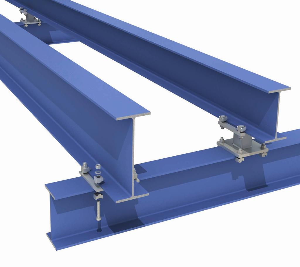
4 4 Girder Clamps by Lindapter Girder Clamp - The Connection Concept Lindapter products provide a faster, cost-effective alternative to on-site drilling or welding and are designed to reduce installation time and labour costs. A high strength, permanent (or temporary) connection is quickly achieved by clamping two steel sections together. Quick and easy to install DECKING FIXINGS SUPPORT FIXINGS FLOOR FIXINGS HOLLO-BOLT LIFTING POINTS RAIL FIXINGS GIRDER CLAMPS REASONS TO USE... Step 1 Bring the location plate and the lower beam into position below the upper beam. Turn to page 6 to see the components of a Girder Clamp in more detail. Save time and money Clamping two steel sections together avoids time-consuming welding or conventional drilling and bolting. kn Step 2 Fit the bolts with two Lindapter clamps, any packings required, a nut and a washer. High strength Lindapter clamps are manufactured from high strength materials to resist high load requirements and harsh environments. Adjustable Quickly align steel sections by sliding the section into the correct position before tightening the Girder Clamp to complete the installation. x Step 3 Using a torque wrench, simply tighten each bolt to the recoended torque. Safer connections On-site drilling and welding is avoided, removing the need for hot work permits and encouraging safer site conditions. Industry leading approvals Lindapter has earned a reputation synonymous with safety and reliability, gaining multiple independent approvals. Further details can be found on page 74. Free connection design Lindapter s experienced Engineers can design a bespoke connection based on your specific requirements free of charge. See page 75 for more details. Watch installation videos of Girder Clamps and many more products at +44 (0) Lindapter International 2016
 The original configuration is designed to secure steel")

 This configuration utilises a High Slip Resistance (HSR) clamp per bolt to achieve a secure connection to vertical columns.")
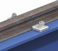
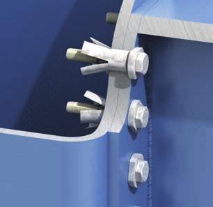
5 Girder Clamps by Lindapter 5 Typical Configurations The Girder Clamp represents a range of Lindapter products that are compatible with virtually any shape or size of steel section and can withstand loading conditions in a wide variety of applications, for example: STANDARD ADJUSTABLE HIGH SLIP RESISTANCE Beam-to-beam (tensile loading) The original configuration is designed to secure steel sections and resist tensile loading. It features a pre-drilled location plate that is placed between the beams to locate the four bolts. Each bolt has two Lindapter components to clamp the flange iediately above and below the plate. For thick beams, a packing piece is required to raise the height of the clamps to enable the product to sit correctly on the beam. See the components of a Girder Clamp in more detail on page 6. Beam-to-column (slip resistance) This configuration utilises a High Slip Resistance (HSR) clamp per bolt to achieve a secure connection to vertical columns. An end plate is pre-fabricated to the section that will be joined to the column. The purpose of this plate is to locate the bolts and provide a fastening position for the Lindapter clamps. Lindapter s range of HSR clamps can be found on pages Inclined beam-to-beam (combined loading) A fabricated assembly, optimised with Lindapter s adjustable HSR clamps to resist both tensile loading and slip. This solution adjusts to fit a wide range of flange thicknesses for added convenience. Lindapter can design and supply the entire assembly to suit individual applications. Read more about the free connection design service on page 6. More examples of typical Lindapter configurations can be found on pages Alternatively, visit the website. GIRDER CLAMPS RAIL FIXINGS LIFTING POINTS HOLLO-BOLT FLOOR FIXINGS SUPPORT FIXINGS DECKING FIXINGS Lindapter International (0)


6 GENERAL NOTES: Assembly Data: Factor of Safety : Static Tensile SWL = 23.2 kn 5 : 1 Static Slip Resistance Factor of Safety : SWL = 1.4 kn 5 : 1 Lindapter Fastener Tightening Torque = 69 Nm For combined loadings the current relevant national standard should be taken into consideration REV. DESCRIPTION PROJECT DRAWING TITLE CUSTOMER ENQUIRY N. DRAWN SCALE: DWG. NO. DO NOT SCALE THIS DRAWING THIS DRAWING AND THE COPYRIGHT THEREIN ARE THE PROPERTY OF LINDAPTER INTERNATIONAL. IT IS ISSUED ON THE CONDITION THAT IT MUST NOT BE USED, COPIED, DISTRIBUTED OR EXHIBITED WITHOUT WRITTEN PERMISSION AND CONSENT. THE DRAWING MUST ALSO NOT BE USED FOR ANY OTHER PURPOSE THAN WHICH IT IS ISSUED. IT IS THE RESPONSIBILITY OF THE ENGINEER TO PERFORM ALL REASONABLE CHECKS ON THE SUPPORTING AND SUPPORTED MEMBERS. THAT IS LOCAL TO THE CONNECTION AND THE LINDAPTER COMPONENTS, BOTH FOR THE LOAD APPLIED AND THE CLAMPING FORCE GENERATED FROM THE TIGHTENING OF THE FASTENERS. WHERE NECESSARY WORKMANSHIP FOR ITEMS SHOWN ON THIS DRAWING SHOULD COMPLY WITH THE RELEVANT SECTIONS OF THE NATIONAL STRUCTURAL STEELWORK SPECIFICATION (NSSS) FOR BUILDING CONSTRUCTION 5TH EDITION CE MARKING VERSION. IF FELT NECESSARY, WHERE EXCESSIVE VIBRATION MAY BE 5. A CONCERN, IT IS ACCEPTABLE FOR CERTAIN TYPES OF ANTI-VIBRATION LOCKING DEVICES SUCH AS, BUT NOT LIMITED TO, PROPRIETARY WASHERS AND NUTS TO BE USED WITH LINDAPTER COMPONENTS AND/OR ASSEMBLIES; SPRING WASHERS OF ANY TYPE ARE NOT RECOMMENDED. IN THESE SITUATIONS IT IS IMPORTANT THAT THE MANUFACTURER'S INSTALLATION INSTRUCTIONS ARE FOLLOWED. NO GUARANTEES OR WARRANTIES ARE IMPLIED. DRAWING NOTES: 1. DIMENSIONS ARE IN MM 2. TOLERANCES: 3. ANGULAR: BEND 4. MATERIAL COATINGS TO BE SPECIFIED BY THE ENGINEER DATE NOT TO SCALE WEIGHT: BY CHECKED REV. DATE 6 Girder Clamps by Lindapter Girder Clamp Configuration A Girder Clamp is a connection system configured with components to suit specific application requirements, for example high tensile loading or high corrosion resistance. Take advantage of the free connection design service to find the best solution for your connection requirement. Standard Lindapter Girder Clamp components DECKING FIXINGS SUPPORT FIXINGS FLOOR FIXINGS HOLLO-BOLT LIFTING POINTS RAIL FIXINGS GIRDER CLAMPS The standard configuration consists of Type A and Type B clamps. See pages for more examples. Standard Hardened Washer (200 Hv). Lindapter Clamps Dependent on the application, different clamps can be used (See page 7). Need some help? Try Lindapter s free connection design service today! For your next project, simply contact Lindapter s team of experienced Engineers and they will advise a suitable solution for you free of charge, providing drawings in 2D or interactive 3D formats as well as CAD files that can be imported into all major software applications. Provide the details below and Lindapter will do the rest! Steel sizes to be used or flange width / thickness Loads to be resisted (e.g. 10kN tension and 15kN slip) General arrangement sketch or verbal description Project Name / Title / Location (optional) This is just one part of Lindapter s service that includes: Free design proposal Packings (if required) Increase the clamping range to suit thick beams. 3D 2D / 3D drawings Standard Hex Nut (Property Class 8 or 10). Quotation Location Plate (can be supplied) An essential part of the assembly that enables all the components to be located in the correct position. A Top Beam Flange Width = 203 Flange Thickness = 15.5 Lower Beam Flange Width = 102 Flange Thickness = 6 14 THRU DETAIL A SCALE 1 : 1.5 Global distribution M12 x 70 Long Setscrew, Property Class 8.8, with Class 8 Nut & Plain Washer Lindapter B12L Clamp Lindapter P1S12 Packer Location Plate Lindapter A12M Clamp 10 Standard Hexagon Bolt / Setscrew Property Class 8.8 or 10.9, dependent on the clamp type. Safe working load up to 78.8kN tensile or 9kN slip resistance (size M24 Type A/B clamps). For higher loads up to 250kN tensile or 70kN slip resistance, see Type AF on page 14. GC001-1 Connection Details SWXXXX-XX Installation guidance (0) Lindapter International 2016
7 Girder Clamps by Lindapter 7 Product Comparison The table below shows the various components that can be assembled in a Girder Clamp arrangement. Each product has specific properties, for example the Type AF heavy duty clamp can resist tensile loads up to 250kN when used with four bolts (property class 10.9) in a Girder Clamp assembly. Single Components Product Other Clamp Systems (these products do not require a location plate) Also available Parallel Flanges Lindapter Rail Fixings See pages for more information Tapered Flanges Tensile High Slip Resistance Low Temp. Down to -60 o C Slotted Clearance Holes Lindapter Lifting Points See pages for more information Adjustable Type A page Type B page Type AAF page Type AF page Type CF page Type LR page Type D2 page Type LS page Type RC page Product Parallel Flanges Tapered Flanges Tensile High Slip Resistance Low Temp. Down to -60 o C Slotted Clearance Holes Adjustable Type F9 page Type FC page GIRDER CLAMPS RAIL FIXINGS LIFTING POINTS HOLLO-BOLT FLOOR FIXINGS SUPPORT FIXINGS DECKING FIXINGS Lindapter International (0)

8 8 Girder Clamps by Lindapter Type A Lindapter s standard clamp is used to resist moderate tensile loading. Can also be used with Type B in a Girder Clamp configuration. Nose Recess DECKING FIXINGS SUPPORT FIXINGS FLOOR FIXINGS HOLLO-BOLT LIFTING POINTS RAIL FIXINGS GIRDER CLAMPS Clamping Area Skirt CE Mark, DIBt, Lloyd s Register and TÜV approved. Recessed top holds the bolt captive while the nut is tightened. Ideal for parallel flanges. Supports up to 78.8kN tensile in a four bolt configuration. For higher loads the Type AF should be used, see page 14. Material: Malleable iron, zinc plated / hot dip galvanised. Product T Bolt 8.8 Y Safe Working Loads (5:1 FOS) Tensile / 1 Bolt X Slip Resistance / 2 Bolts Tail (short, medium or long) Packings are available to increase the clamping range, see page 10. Location plate / end plate details can be found on page 11. V Tightening Torque Dimensions Y X Tail Length V T Width short medium long kn kn Nm A08 M A10 M A12 M A16 M A20 M A24 M For Characteristic Resistances when designing a connection to Eurocode 3 (ETA 13/0300, DOP 0003), please contact Lindapter. +44 (0) Lindapter International 2016
 CE Mark, DIBt, Lloyd s Register and TÜV approved. Flat top allows the bolt head or nut to rotate.")
9 Girder Clamps by Lindapter 9 Type B The flat-top version of Lindapter s standard clamp, for moderate tensile loading. Can also be used with Type A in a Girder Clamp configuration. Nose Flat Top Clamping Area Skirt Tail (short, medium or long) CE Mark, DIBt, Lloyd s Register and TÜV approved. Flat top allows the bolt head or nut to rotate. Suitable for use with bolts, studs, tie rods, J-bolts. Supports up to 78.8kN in a tensile four bolt configuration. For higher loads the Type AF should be used, see page 14. Material: Malleable iron, zinc plated / hot dip galvanised. Product T Bolt 8.8 Y X Safe Working Loads (5:1 FOS) Tensile / 1 Bolt V Packings are available to increase the clamping range, see page 10. Location plate / end plate details can be found on page 11. Slip Resistance / 2 Bolts Tightening Torque Dimensions Y X Tail Length V T Width short medium long kn kn Nm B08 M B10 M B12 M B16 M B20 M B24 M For Characteristic Resistances when designing a connection to Eurocode 3 (ETA 13/0300, DOP 0003), please contact Lindapter. GIRDER CLAMPS RAIL FIXINGS LIFTING POINTS HOLLO-BOLT FLOOR FIXINGS SUPPORT FIXINGS DECKING FIXINGS Lindapter International (0)
 and the correct combination of packing pieces should be used.")
10 10 Girder Clamps by Lindapter Packing Pieces for Types A and B These packing pieces are compatible with the Type A and Type B clamps and are used to increase the clamping range to suit flange thicknesses. Types A and B are available with three different tail lengths (short, medium or long) and the correct combination of packing pieces should be used. Packing Pieces Also Available DECKING FIXINGS SUPPORT FIXINGS FLOOR FIXINGS HOLLO-BOLT LIFTING POINTS RAIL FIXINGS GIRDER CLAMPS Type CW Product Bolt Size Dimension T () CW08* M8 2 CW10 M10 2 CW12 M CW16 M16 3 CW20 M20 4 CW24 M24 4 * CW08 is only available zinc plated. Type P1 / P2 short Product Tail Length / Packing Combinations Bolt Size Choose the correct Type A/B configuration for your application using the table below. Please note these calculations are for beams up to and including 5 O sloped flanges. T Dimension T () P1S08 M8 4 P1S10 M10 5 P1S12 M12 6 P1S16 M16 8 P1S20 M20 10 P1S24 M24 12 P2S08 M8 8 P2S10 M10 10 P2S12 M12 12 P2S16 M16 16 P2S20 M20 20 P2S24 M24 24 Type W Mild steel, zinc plated / hot dip galvanised. Mild steel, malleable iron, zinc plated / hot dip galv. Mild steel, malleable iron, zinc plated / hot dip galv. Product Bolt Size Note: The Type W is used to fill the recess in the Type A to convert it into a flat top clamp to enable the bolt head or nut to be rotated. Flange Thickness M12 M16 M20 M24 A/B CW P1S P2S A/B CW P1S P2S A/B CW P1S P2S A/B CW P1S P2S 5 S S M S S M S S M S M S M S L L M S M L S M L S S M S S L S S L M S L S S L L M S L M L S S M L M S S 1-1 L S L S 1-1 L M L M 1-1 L S S L L M S S L L M M M M M S L S S S L S S L S 2-1 M L M L 1-1 M S T Dimension T () W08 M8 4 W10 M W12 M12 6 W16 M16 8 W20 M20 10 For example, a size M24 Type A/B on a 26 flange requires 1 x Type A/B short tail (S), 1 x Type CW (CW) and 1 x Type P1 short (P1S). T A/B = Type A/B S = A/B short M = A/B medium L = A/B long CW = Type CW P1S = Type P1 short P2S = Type P2 short For thicker flanges please contact Lindapter. +44 (0) Lindapter International 2016
11 Location and End Plates for Types A and B These plates ensure the clamps and bolts are located in the correct position relative to the supporting steelwork. If you would like help choosing a suitable plate, please contact Lindapter. Girder Clamps by Lindapter 11 Location Plate What is it? Location plates are simple fabricated items designed to sit between the two sections to be clamped together to ensure the bolts are fixed at the correct centres. Material: Structural mild steel grade S275 JR or JO. (Steel grade to be specified by the qualified Engineer. For other grades contact Lindapter). Bolt Size End Plate What is it? End plates are simple fabricated items that are pre-welded to support frames, bracket or sections, allowing connection to the supporting structure with standard Lindapter clamps. Bolt Size Hole Ø d Hole Ø d Plate Thick. Plate Thick. 1) Hole Centres C1 Hole Centre C1 Length / Width min L1 Length min L1 Hole Centres C2 Hole Centre min C2 Length / Width min L2 M8 9 6 B1 + 9 B B2 + 9 B M B B B B M B B B B M B B B B M B B B B M B B B B Material: Structural mild steel grade S275 JR or JO. (Steel grade to be specified by the qualified Engineer. For other grades contact Lindapter). PLATE DIMENSIONS L1 = Plate Length, L2 = Plate Width, B1, B2 = Flange Width, C1, C2 = Hole Centres, d = Hole Ø PLATE DIMENSIONS L1 = Plate Length, L2 = Plate Width, B = Flange Width, C1, C2 = Hole Centres, d = Hole Ø To calculate the bolt length, add up the total distance that the bolt will pass through, plus half of the bolt diameter. Then round up the total to the nearest available bolt length. Width min L2 M B + 9 B C M B + 11 B C M B + 14 B C M B + 18 B C M B + 22 B C M B + 26 B C ) Depending on the type of connection and associated end plate use, the thickness may need to be modified to comply with accepted local design codes. B2 d d L1 C1 B1 L1 C1 B C2 L2 C2 L2 GIRDER CLAMPS RAIL FIXINGS LIFTING POINTS HOLLO-BOLT FLOOR FIXINGS SUPPORT FIXINGS DECKING FIXINGS Lindapter International (0)

 Note: Y, X and T will vary depending on the thickness of V. High slip resistance for tensile, frictional and combined load applications.")
12 12 Girder Clamps by Lindapter Type AAF This adjustable High Slip Resistance (HSR) clamp is easy to install and provides high load capacities even in low temperature environments. DECKING FIXINGS SUPPORT FIXINGS FLOOR FIXINGS HOLLO-BOLT LIFTING POINTS RAIL FIXINGS GIRDER CLAMPS Nose Rocking Washer Tail Packings are available to increase the clamping range, see page 16. Location plate / end plate details can be found on page 17. Product Y Size X Bolt Safe Working Loads Dimensions Property Class T V Tensile Resistance / 1 Bolt (FOS 4.5:1) Note: Y, X and T will vary depending on the thickness of V. High slip resistance for tensile, frictional and combined load applications. Self-adjusts to suit flange thicknesses 6 to 40 (size M20). Safe working loads apply in temperatures as low as -60 C. Suitable for parallel and tapered flanges up to 10. Hot dip galvanised as standard. Material: Low temperature SG iron to EN 1563, hot dip galvanised to EN ISO Slip Resistance 1) / 2 Bolts (FOS 2:1) Tightening Torque Clamping Range 3) V HIGH SLIP RESISTANCE Y X T Width Painted Galv. Steelwork 2) Steelwork kn kn kn Nm AAF12 M AAF16 M AAF20 M AAF12 M (100*) AAF16 M (250*) AAF20 M (450*) ) Slip Resistance figures are based on Type AAF and Location Plates in hot dip galvanised finish calculated against slip (movement exceeding 0.1). 2) Shot blast and painted steelwork. 3) For thicker flanges, packing pieces AFP1 and AFP2 are available (for AAF12 and AAF16 only) or packing piece AAFP3 (for AAF20 only). See page 16. * Torque for lubricated bolts +44 (0) Lindapter International 2016

 clamps, designed specifically for frictional")


13 Girder Clamps by Lindapter 13 Typical Applications for the Type AAF The Type AAF is one of three products in Lindapter s range of High Slip Resistance (HSR) clamps, designed specifically for frictional applications and high tensile loading. This heavy duty clamp is used in many diverse industries and situations, here are some application examples: Note: Can be used with strut / metal framing with reduced torque, please contact Lindapter to ensure suitability of the component for application. GIRDER CLAMPS RAIL FIXINGS LIFTING POINTS HOLLO-BOLT FLOOR FIXINGS SUPPORT FIXINGS DECKING FIXINGS Lindapter International (0)


 Steel Type AF + AFW Type AFW (page 16) converts the recess to a flat top (also required for pre-loadable bolts to BS EN 14399).")
14 14 Girder Clamps by Lindapter Type AF A heavy duty clamp offering the highest load capacities of all Lindapter s High Slip Resistance clamps. Recess DECKING FIXINGS SUPPORT FIXINGS FLOOR FIXINGS HOLLO-BOLT LIFTING POINTS RAIL FIXINGS GIRDER CLAMPS Nose Skirt T2 T1 High slip resistance for tensile, frictional and combined load applications. Static slip resistance of 70kN or tensile resistance 250kN (4-bolt config., size M24). Recess holds the bolt head captive (property class 8.8 or 10.9 bolts to BS EN 15048). Suitable for parallel and tapered flanges up to 10. Hot dip galvanised as standard. Material: SG iron to EN 1563, hot dip galvanised to EN ISO Product Size Y Bolt Safe Working Loads Dimensions Property Class X Tail (short or medium) V Tensile Resistance / 1 Bolt (FOS 5:1) Slip Resistance 1) / 2 Bolts (FOS 2:1) Painted Galv. Steel 2) Steel Type AF + AFW Type AFW (page 16) converts the recess to a flat top (also required for pre-loadable bolts to BS EN 14399). Tightening Torque Tail Length V HIGH SLIP RESISTANCE Choose the correct tail length / packing combination to suit the flange thickness, see page 16. Location plate / end plate details can be found on page 17. Y X T1 T2 Width short medium Type Type AF AF with AFW kn kn kn Nm AF12 M AF16 M AF20 M AF24 M AF12 M (100*) AF16 M (250*) AF20 M (450*) AF24 M ) (800*) ) Slip Resistance figures are based on Type AF and Location Plates in hot dip galvanised finish calculated against slip (movement exceeding 0.1). 2) Shot blast and painted steelwork. 3) 3.2:1 Factor of Safety. * Torque for lubricated bolts. +44 (0) Lindapter International 2016
 Anti-rotation marks Legs Can be combined with any Lindapter HSR clamps when used with property class 8.")

15 Girder Clamps by Lindapter 15 Type CF Hooks over the flanges of beams, angles and channels to connect steel sections that do not face, such as connecting horizontal beams with vertical columns. Nose Y V Product X Bolt 8.8 T Tensile Resistance / 1 Bolt (FOS 5:1) Anti-rotation marks Legs Can be combined with any Lindapter HSR clamps when used with property class 8.8 bolts; see table below for safe working loads. Suitable for parallel and tapered flanges up to 8 o. Material: SG iron to EN 1563, hot dip galvanised to EN ISO CF combinations with other Lindapter clamps Location plate / end plate details can be found on page 17. Safe Working Loads Slip Resistance 1) / 2 Bolts (FOS 2:1) Tightening Torque Clamping Range V Dimensions Y X T Width Painted Galv. Steelwork 2) Steelwork kn kn kn Nm CF12 M CF16 M CF20 M CF / A 3) M CF / A 3) M CF / A 3) M CF / AF M CF / AF M CF / AF M HIGH SLIP RESISTANCE 1) Slip Resistance figures are based on Type CF and Location Plates in hot dip galvanised finish calculated against slip (movement exceeding 0.1). 2) Shot blast and painted steelwork. 3) Also applies to Type B (page 9), Type LR (page 18), Type D2 (page 19) and Type BR (page 31). GIRDER CLAMPS RAIL FIXINGS LIFTING POINTS HOLLO-BOLT FLOOR FIXINGS SUPPORT FIXINGS DECKING FIXINGS Lindapter International (0)
 and the correct combination of packing pieces should be used, see the table at the bottom of the page.")
16 16 Girder Clamps by Lindapter Packing Pieces for Types AF and AAF Packing pieces are used to increase the clamping range to suit a range of flange thicknesses. The Type AF is available with two different tail lengths (short and medium) and the correct combination of packing pieces should be used, see the table at the bottom of the page. Packing Pieces Also Available DECKING FIXINGS SUPPORT FIXINGS FLOOR FIXINGS HOLLO-BOLT LIFTING POINTS RAIL FIXINGS GIRDER CLAMPS Type AFCW Mild steel, hot dip galvanised. Product Bolt Size Dimension T () AF12CW* M12 2 AF16CW* M16 2 AF20CW M20 2 * Also compatible with Type AAF clamp. Note: The AFCW has a slight bend along its centre line which flattens out during installation. Tail Length / Packing Combinations Choose the correct Type AF configuration for your application using the table below. Please note these calculations are for parallel flanges and beams up to 10 O slopes only. Flange M12 M16 M20 M24 Thickness AF AFCW AFP1 AFP2 AF AFCW AFP1 AFP2 AF AFCW AFP1 AFP2 AF AFP1 AFP2 5 S S S S S S S S S S S S S S S S S S S M S S S M S S S S M S S M M S S M M M S M S M S 1-19 M M M S 1-20 S M M S 1-21 M M M S 1-22 M M M S 1-23 M M M S M 1-1 M M S S M M S M 2-1 M S S M 2-1 M 1-1 S M - - T Type AFP1 / AFP2 / AAFP3 Mild steel, hot dip galvanised. Product Bolt Size Flange Thickness Dimension T () AF12P1* M12 5 AF16P1* M16 5 AF20P1 M20 5 AF24P1 M24 5 AF12P2* M12 10 AF16P2* M16 10 AF20P2 M20 10 AF24P2 M24 10 AAF20P3* M20 20 * Also compatible with Type AAF clamp. T Type AFW SG iron, mild steel, hot dip galvanised. Product Bolt Size M12 M16 M20 M24 Dimension T () AFW12 M12 5 AFW16 M16 5 AFW20 M20 6 AFW24 M24 10 Note: The Type AFW is used to fill the recess in the Type AF to convert it into a flat top clamp to enable the bolt head or nut to be rotated. The Type AFW is also required when using pre-loadable bolts to BS EN due to their larger hexagon heads. For example, a size M20 Type AF on a 40 flange requires 1 x Type AF medium tail (M), 1 x Type AFCW and 2 x Type AFP2. AF AFCW AFP1 AFP2 AF AFCW AFP1 AFP2 AF AFCW AFP1 AFP2 AF AFP1 AFP2 28 M S M M M M M M S M M 1-1 M S M M 1-1 M M M M M 1-33 M M M M 1-34 M 1-2 M M M 1-35 S M S M 1-36 S M M M 1-37 M M 1-2 M M 1-38 M S M M M M M M S M M 1-2 M S M M 1-2 M M M M M M S M M M 1-3 M M M S M M M S M M M M M 1-3 M M M S M M S M M M S M M 1-3 M - 2 T AF = Type AF AFCW = Type AFCW AFP1 = Type AFP1 AFP2 = Type AFP2 S = Type AF short M = Type AF medium For thicker flanges please contact Lindapter. +44 (0) Lindapter International 2016
17 Location and End Plates for Types AF, AAF and CF These plates ensure the clamps and bolts are located in the correct position relative to the supporting steelwork. If you would like help choosing a suitable plate, please contact Lindapter. Girder Clamps by Lindapter 17 Location Plate What is it? Location plates are simple fabricated items designed to sit between the two sections to be clamped together to ensure the bolts are fixed at the correct centres. Material: Structural mild steel grade S355 JR, JO or J2. (Steel grade to be specified by the qualified Engineer. For other grades contact Lindapter). Bolt Size Hole Ø d End Plate Plate Thickness Hole Centres C1 What is it? End plates are simple fabricated items that are pre-welded to support frames, bracket or sections, allowing connection to the supporting structure with standard Lindapter clamps. Length / Width min L1 Hole Centres C2 Length / Width min L2 M B B B B M B B B B M B B * B B * M B B B B * Plate width for Type AF size M20 can be reduced to 130 if required. Material: Structural mild steel grade S355 JR, JO or J2. (Steel grade to be specified by the qualified Engineer. For other grades contact Lindapter). Bolt Size Hole Ø d Plate Thickness 1) Hole Centres C1 Length min L1 Hole Centres min C2 Width min L2 M B + 14 B C M B + 18 B C M B + 22 B + 150* 180 C M B + 26 B C B2 PLATE DIMENSIONS L1 = Plate Length, L2 = Plate Width, B1, B2 = Flange Width, C1, C2 = Hole Centres, d = Hole Ø d L1 C1 B1 C2 PLATE DIMENSIONS L1 = Plate Length, L2 = Plate Width, B = Flange Width, C1, C2 = Hole Centres, d = Hole Ø * Plate width for Type AF size M20 can be reduced to 130 if required. 1) Depending on the type of connection and associated end plate use, the thickness may need to be modified to comply with accepted local design codes. To calculate the bolt length, add up the total distance that the bolt will pass through, plus half of the bolt diameter. Then round up the total to the nearest available bolt length. d L1 C1 B C2 L2 L2 GIRDER CLAMPS RAIL FIXINGS LIFTING POINTS HOLLO-BOLT FLOOR FIXINGS SUPPORT FIXINGS DECKING FIXINGS Lindapter International (0)
. For parallel and tapered flanges up to 15.")
 Tensile / 1 Bolt Slot Tail Material: Malleable iron, zinc plated / hot dip galvanised. X Packings are available to increase the clamping range, see page 20.")
18 18 Girder Clamps by Lindapter Type LR A versatile, self-adjusting clamp designed to suit a range of flange thicknesses. Saddle DECKING FIXINGS SUPPORT FIXINGS FLOOR FIXINGS HOLLO-BOLT LIFTING POINTS RAIL FIXINGS GIRDER CLAMPS Nose Leg V Clamping ranges from 3-24 (size M24). For parallel and tapered flanges up to 15. The leg of the saddle prevents the clamp from rotating. The tail spans slotted clearance holes. Product Clip T Y Bolt 8.8 Safe Working Loads (Factor of Safety 5:1) Tensile / 1 Bolt Slot Tail Material: Malleable iron, zinc plated / hot dip galvanised. X Packings are available to increase the clamping range, see page 20. Location plate / end plate details can be found on page 21. Slip Resistance / 2 Bolts Tightening Torque Clamping Range V Dimensions Y X T Width with Saddle kn kn Nm LR10 M LR12 M LR16 M LR20 M LR24 M (0) Lindapter International 2016

 Tensile / 1 Bolt V Packings are available to increase the clamping range, see page 20.")
19 Girder Clamps by Lindapter 19 Type D2 This clamp has an adjustable Setscrew Tail that can be adapted to fit a range of flange thicknesses. Nose Recess Clamping Area T Suitable for parallel and tapered flanges up to 5. Recessed top holds the bolt head captive while the nut is tightened. Type W washer (page 20) can be used to fill the recess. The skirt prevents the clamp from rotating during installation. Product Skirt Y Bolt 8.8 Setscrew Tail X S Safe Working Loads (Factor of Safety 5:1) Tensile / 1 Bolt V Packings are available to increase the clamping range, see page 20. Location plate / end plate details can be found on page 21. Material: Malleable iron, zinc plated / hot dip galvanised. Slip Resistance / 2 Bolts Tightening Torque Dimensions Clamping Range V 1) V 2) Y X S T Width kn kn Nm D210 M M D212 M M D216 M M D220 M M GIRDER CLAMPS RAIL FIXINGS LIFTING POINTS HOLLO-BOLT FLOOR FIXINGS SUPPORT FIXINGS DECKING FIXINGS 1) Setscrew (S) inserted from above. 2) Setscrew (S) inserted from below. Lindapter International (0)

20 20 Girder Clamps by Lindapter Packing Pieces for Types LR and D2 These packing pieces are compatible with the Types LR and D2 fixings and are used to increase the clamping range to suit a range of flange thicknesses. Please select the correct packing combination from the table below. Packing Pieces Also Available DECKING FIXINGS SUPPORT FIXINGS FLOOR FIXINGS HOLLO-BOLT LIFTING POINTS RAIL FIXINGS GIRDER CLAMPS Type P1 long / Type P2 long Product Bolt Size Dimension T () P1L10 M10 5 P1L12 M12 6 P1L16 M16 8 P1L20 M20 10 P1L24 M24 12 P2L10 M10 10 P2L12 M12 12 P2L16 M16 16 P2L20 M20 20 P2L24 M24 24 Packing Combinations for Type LR (Parallel flanges only) Combinations LR P1L P2L M10 M12 Clamping Range M16 M20 M Packing Combinations for Type D2 (Parallel flanges and beams of up to 5 o slope) Combinations D2 P1L P2L M10 Clamping Range M12 M16 M20 1 1) ) Setscrew inverted. T Mild steel, malleable iron, zinc plated / hot dip galv. Tail Length / Packing Combinations Type W IPN Profile T Mild steel, zinc plated / hot dip galvanised. Product Note: The Type W is used to fill the recess in the Type D2 to convert it into a flat top clamp to enable the bolt head or nut to be rotated. Packing Combinations for Type LR (For IPN-Beams of an 8 o slope only) M10 M12 M16 M20 M24 LR P1L P2L LR P1L P2L LR P1L P2L LR P1L P2L LR P1L P2L LR = Type LR P1L = Type P1 long P2L = Type P2 long Bolt Size Dimension T () W08 M8 4 W10 M W12 M12 6 W16 M16 8 W20 M20 10 For thicker flanges please contact Lindapter. +44 (0) Lindapter International 2016
21 Location and End Plates for Types LR and D2 These plates ensure the clamps and bolts are located in the correct position relative to the supporting steelwork. If you would like help with choosing a suitable plate, please contact Lindapter. Girder Clamps by Lindapter 21 Location Plate What is it? Location plates are simple fabricated items designed to sit between the two sections to be clamped together to ensure the bolts are fixed at the correct centres. Material: Structural mild steel grade S355 JR or JO. (Steel grade to be specified by the qualified Engineer. For other grades contact Lindapter). Bolt Size Hole Ø d End Plate Plate Thick. Hole Centres C1 Length / Width min L1 What is it? End plates are simple fabricated items that are pre-welded to support frames, bracket or sections, allowing connection to the supporting structure with standard Lindapter clamps. Hole Centres C2 Length / Width min L2 M B B B B M B B B B M B B B B M B B B B M B B B B Material: Structural mild steel grade S355 JR or JO. (Steel grade to be specified by the qualified Engineer. For other grades contact Lindapter). Bolt Size Hole Ø d Plate Thick. 1) Hole Centres C1 Length min L1 Hole Centres C2 Width min L2 M B + 11 B C M B + 14 B C M B + 18 B C M B + 22 B C M B + 26 B C PLATE DIMENSIONS L1 = Plate Length, L2 = Plate Width, B1, B2 = Flange Width, C1, C2 = Hole Centres, d = Hole Ø PLATE DIMENSIONS L1 = Plate Length, L2 = Plate Width, B = Flange Width, C1, C2 = Hole Centres, d = Hole Ø 1) Depending on the type of connection and associated end plate use, the thickness may need to be modified to comply with accepted local design codes. To calculate the bolt length, add up the total distance that the bolt will pass through, plus half of the bolt diameter. Then round up the total to the nearest available bolt length. B2 d d L1 C1 B1 L1 C1 B C2 L2 C2 L2 GIRDER CLAMPS RAIL FIXINGS LIFTING POINTS HOLLO-BOLT FLOOR FIXINGS SUPPORT FIXINGS DECKING FIXINGS Lindapter International (0)


22 22 Girder Clamps by Lindapter Type LS Providing excellent corrosion resistance, Lindapter s stainless steel clamp self-adjusts to suit a range of flange thicknesses. Nose DECKING FIXINGS SUPPORT FIXINGS FLOOR FIXINGS HOLLO-BOLT LIFTING POINTS RAIL FIXINGS GIRDER CLAMPS Y Tail Made from high strength stainless steel grade 316. Self-adjusts to suit 3-30 flange thicknesses. For parallel and tapered flanges up to 10. The tail spans slotted clearance holes. Product X Bolt A4-70 T V Packings are available to increase the clamping range, see page 23. Location plate / end plate details can be found on page 23. Material: Cast stainless steel grade 316. Tensile / 1 Bolt (FOS 5:1) Safe Working Loads Slip Resistance 1) / 2 Bolts (FOS 2:1) Tightening Torque Clamping Range V Dimensions Y X T Width kn kn Nm LS10 M LS12 M LS16 M LS20 M ) Slip resistance loads calculated against slip (movement exceeding 0.1). +44 (0) Lindapter International 2016

23 Packing Pieces and Plate Details for Type LS Stainless steel packing pieces are available to increase the clamping range of the Type LS, please select the correct packing combination from the table below. This page also contains information for designing location / end plates. Girder Clamps by Lindapter 23 Packing Pieces Type LSP2 Material: Stainless steel grade 316. Product Bolt Size Dimension T () Location Plate What is it? Location plates are simple fabricated items designed to sit between the two sections to be clamped together to ensure the bolts are fixed at the correct centres. Material: Stainless steel grade 304 / 316. Bolt Size Bolt Size LS10P2 M10 10 LS12P2 M12 10 LS16P2 M16 10 LS20P2 M20 10 Hole Ø d End Plate Hole Ø d Plate Thick. Plate Thick. 1) Hole Centres C1 What is it? End plates are simple fabricated items that are pre-welded to support frames, bracket or sections, allowing connection to the supporting structure with standard Lindapter clamps. Material: Stainless steel grade 304 / 316. Hole Centres C1 Length / Width min L1 Hole Centres min C2 Length / Width min L2 M B + 11 B C M B + 14 B C M B + 18 B C M B + 22 B C ) Depending on the type of connection and associated end plate use, the thickness may need to be modified to comply with accepted local design codes. Length / Width min L1 T Hole Centres C2 Packing Combinations for Type LS (For parallel flanges and beams up to a 10 o slope) For example, a size M20 Type LS on a 42 flange requires 2 x Type LSP2. Combinations LS LSP2 M10 PLATE DIMENSIONS: L1 = Plate Length, L2 = Plate Width, B1, B2 = Flange Width, C1, C2 = Hole Centres, d = Hole Ø B2 d L1 C1 B1 PLATE DIMENSIONS: L1 = Plate Length, L2 = Plate Width, B = Flange Width, C1, C2 = Hole Centres, d = Hole Ø d Clamping Range M12 L1 C1 B M16 C2 M For thicker flanges please contact Lindapter. Length / Width min L2 M B B B B M B B B B M B B B B M B B B B L2 C2 L2 GIRDER CLAMPS RAIL FIXINGS LIFTING POINTS HOLLO-BOLT FLOOR FIXINGS SUPPORT FIXINGS DECKING FIXINGS Lindapter International (0)

 Tightening Torque Tail Length V S L H Width kn Nm RCS12 M12 2.6 69 10 6.")


24 24 Girder Clamps by Lindapter Type RC Customised position of hole centre, drilled by Lindapter to suit the application. For flanges of 10 thickness or greater, either parallel or tapered up to 5. DECKING FIXINGS SUPPORT FIXINGS FLOOR FIXINGS HOLLO-BOLT LIFTING POINTS RAIL FIXINGS GIRDER CLAMPS Nose Skirt Tail Material: Forged steel, corrosion protection as required. Hole centre to suit application Safe Working Loads Dimensions Product Bolt 8.8 Tensile / 1 Bolt (FOS 5:1) Tightening Torque Tail Length V S L H Width kn Nm RCS12 M RCS16 M RCS20 M RCS24 M Type F9 A flange clamp for connecting parallel running steel sections with flanges of the same width. Can be used with bolts or threaded rod. Nut Jaws Contact Lindapter to ensure suitability of the component for application. Bolt Single Leg Double Leg Material: Malleable iron, zinc plated / hot dip galvanised. S J V J L Y V H X Product Safe Working Loads Dimensions with without Bolt 8.8 Tensile / 1 Bolt Tightening Clamping Range Y J X Width Bolt Bolt (FOS 5:1) Torque V kn Nm F910NC F910NB M F912NC F912NB M F916NC F916NB M F920NC F920NB M F924NC F924NB M Not suitable for tapered flanges. +44 (0) Lindapter International 2016


25 Girder Clamps by Lindapter 25 Type FC - Flush Clamp A full connection system that adjusts to fit a variety of beam types. This pre-configured assembly does not require a location plate and is ready for assembly out of the box. All-in-one device for connecting steel sections. Adjustable to suit both beam width and flange thickness. Quick and easy to install. For parallel and tapered flanges up to 10. Half Nut Nut Minimum Possible Beam Connection Angles Bottom Beam V Product Flange Width T Bolt 8.8 Body Material: Forged steel, zinc plated plus JS Safe Working Loads (Factor of Safety 5:1) Clamping Range Dimensions Tensile / 4 Bolts Top Beam Slip Resistance / 4 Bolts O 50 O 55 O 65 O 75 O O 50 O 55 O 65 O 75 O O 55 O 55 O 65 O 75 O O 65 O 65 O 65 O 75 O Tightening Torque Flange Thickness V Flange T B Width 1) kn kn Nm FC16 M ) Depending on beam connection angles (see table below). B T Bolt T Flat Washer Special Washer Angle GIRDER CLAMPS RAIL FIXINGS LIFTING POINTS HOLLO-BOLT FLOOR FIXINGS SUPPORT FIXINGS DECKING FIXINGS O 75 O 75 O 75 O 80 O Lindapter International (0)


")
 Type B (page 9) GC001-8 Type")
26 26 Girder Clamps by Lindapter Typical Applications for Girder Clamps Popular connection assemblies are shown below. They represent a fraction of the possibilities as Lindapter s clamps are used all over the world to connect almost every type of steel section. Visit the website for more examples or contact Lindapter to discuss your connection requirement. GC001-1 GC001-4 DECKING FIXINGS SUPPORT FIXINGS FLOOR FIXINGS HOLLO-BOLT LIFTING POINTS RAIL FIXINGS GIRDER CLAMPS Types A + B (pages 8 & 9) GC001-6 Types A + LR (pages 8 & 18) GC Type LR (page 18) Type B (page 9) GC001-8 Type AF (page 14) GC002-3 Types A + B (pages 8 & 9) +44 (0) Lindapter International 2016


")
 Type AAF (page")
 GIRDER CLAMPS RAIL")

27 Girder Clamps by Lindapter 27 Typical Applications for Girder Clamps Examples of popular connection arrangements are continued below. GC003-4 GC003-5 Type AF (page 14) GC004-1 Type A (page 8) GC004-5 Type AF (page 14) Type AAF (page 12) GC004-2 Type B (page 9) GC005-1 Type A (page 8) GIRDER CLAMPS RAIL FIXINGS LIFTING POINTS HOLLO-BOLT FLOOR FIXINGS SUPPORT FIXINGS DECKING FIXINGS Lindapter International (0)


 GC006-1 Types B + CF (pages 9 &")
 GC006-2 Type B (page 9)")
28 28 Girder Clamps by Lindapter Typical Applications for Girder Clamps More examples of popular connection assemblies are shown below. GC005-2 GC005-3 DECKING FIXINGS SUPPORT FIXINGS FLOOR FIXINGS HOLLO-BOLT LIFTING POINTS RAIL FIXINGS GIRDER CLAMPS Type A (page 8) GC006-1 Types B + CF (pages 9 & 15) GC006-3 Type A (page 8) Type AAF (page 12) GC006-2 Type B (page 9) GC006-6 Type A (page 8) +44 (0) Lindapter International 2016


 GC009-2")
 GC010-1 Type B (page")

29 Girder Clamps by Lindapter 29 Typical Applications for Girder Clamps Examples of popular connection arrangements are continued below. Contact Lindapter to discuss your connection requirement. GC008-2 Types A, B + CF (pages 8, 9 & 15) GC009-2 Type AF (page 14) GC011-1 Type B (page 9) GC008-4 Types AF + CF (pages 14 & 15) GC010-1 Type B (page 9) GC012-1 Type LS (page 22) GIRDER CLAMPS RAIL FIXINGS LIFTING POINTS HOLLO-BOLT FLOOR FIXINGS SUPPORT FIXINGS DECKING FIXINGS Lindapter International (0)
. Rail Fixings pages 30-33 For securing rails or crane lines in low speed applications such as ground track, elevated rail and overhead")

30 30 Rail Fixings by Lindapter The popular Type HD provides lateral adjustability to allow the quick and precise alignment of rails (see page 32). Rail Fixings pages For securing rails or crane lines in low speed applications such as ground track, elevated rail and overhead gantries. These fixings are used in a wide range of environments including, train maintenance depots, industrial facilities, water treatment plants, dam/dockside cranes, automated warehouses and power stations. Type BR page 31 Type HD page (0) Lindapter International 2016
 Material: Malleable iron, zinc plated / hot dip galvanised.")
31 Rail Fixings by Lindapter 31 Type BR A basic clamp for securing low speed rail or steel beams with either parallel or tapered flanges up to 8. The tail is available in two lengths and spans slotted clearance holes. Nose Flat Top Clamping Area Skirt Tail (short or medium) Material: Malleable iron, zinc plated / hot dip galvanised. T Y X Safe Working Loads (FOS 5:1) Dimensions Bolt 8.8 Tensile / 1 Bolt Slip Resistance / 2 Bolts Tightening Torque Tail Length V Y X short medium T Width kn kn Nm BR12 M BR16 M BR20 M Contact Lindapter to ensure suitability of the component for application. Packing Pieces and Combinations for Type BR Type CW Mild steel, zinc plated / hot dip galv. Product Bolt Size Dimension T () CW12 M CW16 M16 3 CW20 M20 4 Type P1 short / Type P2 short Mild steel, malleable iron, zinc plated / hot dip galv. Product Bolt Size Dimension T () P1S12 M12 6 P1S16 M16 8 P1S20 M20 10 P2S12 M12 12 P2S16 M16 16 P2S20 M20 20 T T V Packing Combinations for Type BR (For rails up to and including 8 o slope) Flange Thickness M12 M16 M20 BR CW P1S P2S BR CW P1S P2S BR CW P1S P2S 5 S M S S S S M M S S S S S S M M M S M S S S S S M S M S S S S M S M S S M S M S 1-1 M S M 1-1 S M M 1-1 S M S S M M 2-1 M M M M M S S 1-1 S M S 1-1 S S M 1-1 S S S 2-1 M S S 2-1 M M M 2-1 M S 1-2 M 2-1 S 1-1 S = BR short M = BR medium CW = Type CW P1S = P1 short P2S = P2 short For thicker flanges please contact Lindapter. GIRDER CLAMPS RAIL FIXINGS LIFTING POINTS HOLLO-BOLT FLOOR FIXINGS SUPPORT FIXINGS DECKING FIXINGS Lindapter International (0)


 Tight. Torque High Lateral Conditions SWL (FOS 4:1) Tight. Torque Leg V Stud Length H Dimensions Distances 1) Width Lateral Adjust.")
32 32 Rail Fixings by Lindapter Type HD This convenient fixing provides lateral adjustability for fast and precise rail alignment in low speed applications. Type HD Hard / Soft Clip DECKING FIXINGS SUPPORT FIXINGS FLOOR FIXINGS HOLLO-BOLT LIFTING POINTS RAIL FIXINGS GIRDER CLAMPS Leg Plug Skirt Type HD Spring Clip Nose Elastomer Spring Suitable for all rails with tapered flanges and crane speeds up to 60m/min. Safely and easily secures rail using only hand tools. Please contact Lindapter for wheel loads above 400kN or lateral loads higher than wheel loads. Can be supplied with a nylon insulator, please contact Lindapter to ensure suitability of component for application. Material: SG iron, corrosion protection as requested. Product Clip Type Bolt 8.8 Normal Lateral Conditions SWL (FOS 4:1) Tight. Torque High Lateral Conditions SWL (FOS 4:1) Tight. Torque Leg V Stud Length H Dimensions Distances 1) Width Lateral Adjust. L Plate Width min A Y X W kn Nm kn Nm HD20H Hard M F - 8 F / B HD20S Soft M F - 5 F / B HD20SP Spring M F - 7 F / B HD20S-P Soft + Pad M F 2) F / B HD20SP-P Spring + Pad M F - 2 2) F / B HD24H Hard M F - 8 F /- 8 B HD24S Soft M F - 4 F /- 8 B HD24SP Spring M F - 7 F /- 8 B HD24S-P Soft + Pad M F+ 1 2) F /- 8 B HD24SP-P Spring + Pad M F - 2 2) F /- 8 B ) Based on plug set at 3 o clock position. 2) Based on 5 thick resilient pad. Note: Leg length V for use with rail sections only with tapered base. For parallel sections please refer to Lindapter. +44 (0) Lindapter International 2016

 Position clip on the bolt or stud. Place plug in the 3 o clock position and loosely tighten the nut.")
33 Rail Fixings by Lindapter 33 Type HD Variants Type HD Soft Clip Leg length (V) should be selected to allow vertical rail movement caused by rail wave, whilst holding the rail in precise alignment laterally. Rail ends need to be fixed. H Type HD Spring Clip This version incorporates an elastomer spring* into the nose of the product, designed to provide some vertical restraint to the rail whilst still allowing it to lift with rail wave. H X X Y Y F F How to install... B A B A 1) Position clip on the bolt or stud. Place plug in the 3 o clock position and loosely tighten the nut. 2) Rotate the built-in nut profile in a clockwise direction from the 3 o clock position to locate the clip against the rail. Laterally adjust rail if required and apply recoended torque to the hexagon nut. Watch the installation video at V V Type HD Hard Clip Leg length (V) should be selected to clamp rail down tightly and allow no vertical rail movement. Not to be used when the rail is supported by a resilient pad. Resilient Pad Spring clip and soft clip can be used with a resilient pad to further decrease track running noise / structural vibration by levelling out the irregular contact between the surface and the rail and to spread the wheel load evenly over a wider area. Resilient Pad (not supplied by Lindapter) * Manufactured from high density synthetic polymer with a Shore A hardness of 90-97, the elastomer spring has a high resistance to abrasion and is unaffected by salt water and most chemicals. H X Y F B A W V V The nut shown above is in the 3 o clock position. +L -L GIRDER CLAMPS RAIL FIXINGS LIFTING POINTS HOLLO-BOLT FLOOR FIXINGS SUPPORT FIXINGS DECKING FIXINGS Lindapter International (0)

34 34 Lifting Points by Lindapter The versatile Type ALP not only provides lateral adjustability, it also adjusts to suit different beam sizes and the orientation of the lift (see page 36). Lifting Points pages Lindapter s lifting points are used in a variety of industries to support the lifting and rigging of heavy equipment. Applications vary from suspending overhead audio-visual kit in theatres to lifting drilling risers onto offshore oil platforms. Type ALP (Standard) page 36 Type LP (Bespoke) page (0) Lindapter International 2016


35 Lifting Points by Lindapter 35 Lifting Point Configuration Lindapter manufactures Lifting Points that are configured with adjustable, high strength components to suit heavy loads up to 200kN SWL. Take advantage of the Free Connection Design service for advice on the best solution for your connection. Quick and easy to install Offer the pre-assembled location plate up to the beam ensuring it is positioned centrally to it. STANDARD BESPOKE Step 1 Type ALP Step 2 Assemble the clamps and tighten to the recoended torque. Ideal for most applications up to 3t (29.4kN), this assembly self-adjusts to suit a range of flange thicknesses. For further convenience, the slotted holes in the location plate allow the clamp to adapt to different beam widths, often allowing contractors to use just one type of lifting point throughout a project. Lindapter s standard lifting point is iediately available off-the-shelf. See the Type ALP and its components in more detail on page 36. Type LP Watch the installation at For large steel sections or loads up to 200kN, Lindapter manufactures custom-made solutions for specific application requirements. Whatever the application, Lindapter s durable products are valued for their quality and reliability, and provide contractors with a safe, quick and convenient lifting system. See the Type LP and its components in more detail on page REASONS TO USE 1) Quick and easy to install using standard hand tools. 2) Easy to align / reposition. 3) Maximum safe working load up to 200kN (Type LP). 4) For parallel and tapered flanges up to 10 o. 5) Utilises Lindapter clamps approved by TÜV. 6) Free Connection Design service available. support@lindapter.com your connection details and Lindapter s experienced Engineers will do the rest! GIRDER CLAMPS RAIL FIXINGS LIFTING POINTS HOLLO-BOLT FLOOR FIXINGS SUPPORT FIXINGS DECKING FIXINGS Lindapter International (0)

. Large load ring can be set to suit the lift orientation. X Torque Figures Bolt 8.")
36 36 Lifting Points by Lindapter Type ALP Lindapter s standard rigging and lifting solution adjusts to suit the beam width, flange thickness and orientation of the lift. Safely supports loads up to three metric tonnes. DECKING FIXINGS SUPPORT FIXINGS FLOOR FIXINGS HOLLO-BOLT LIFTING POINTS RAIL FIXINGS GIRDER CLAMPS Type AAF Clamps Location Plate Product Load Ring Countersunk Bolts Bolt 10.9 Countersunk Bolts X U Torque Nm Load Ring 90 o Available off-the-shelf with a safe working load up to 3t (29.4kN). Large load ring can be set to suit the lift orientation. X Torque Figures Bolt 8.8 Type AAF Bolts V Clamping Range Flange Thickness V Beam Width U Torque Nm Safe Working Loads (4:1 Factor of Safety) STANDARD SOLUTION Adjusts to suit the 5 to 26 flange thickness and 70 to 210 beam widths. Suitable for parallel and tapered beams up to 10. Ensure that the supporting steelwork is suitable for the applied load. For larger steel sections or heavier loads, please refer to the Type LP (page 37), Lindapter s bespoke Lifting Points manufactured to suit individual applications. Material: Type AAF clamps (low temperature SG iron, hot dip galvanised), Location Plate (mild steel, hot dip galvanised) and Load Ring (forged steel, painted). Max. angle of load X ALP 3T-1 M M t (29.4kN) 18 o +44 (0) Lindapter International 2016
 Lifting Point with 4 Type AF clamps Eye Bolt LP6 (10kN to 100kN SWL) Lifting Point with 6 Type AF clamps Load Ring The Type LP can be supplied with either an Eye Bolt or Load")
 determines the number of Type AF clamps.")
 BESPOKE SOLUTION Type LP6 (with Load Ring) 200kN For example, the LP6 has six M24 Type AF clamps to create a Safe Working Load of 100kN (4:1 Factor of Safety).")
37 Lifting Points by Lindapter 37 Type LP Utilising Lindapter s high strength Type AF clamps for heavy loads, the Type LP is available in bespoke configurations up to 200kN SWL. LP4 (4kN to 45kN SWL) Lifting Point with 4 Type AF clamps Eye Bolt LP6 (10kN to 100kN SWL) Lifting Point with 6 Type AF clamps Load Ring The Type LP can be supplied with either an Eye Bolt or Load Ring. Please state your requirement when ordering. Bespoke Configurations Lindapter manufactures customised Lifting Points to meet individual requirements, two examples are shown on the right. These bespoke connections are designed to specific application requirements, such as vertical loads, loads at an angle and rotation of up to 360. The product designation, i.e. LP(#) determines the number of Type AF clamps. Bespoke solutions up to 200kN are also available. Type LP4 (with Eye Bolt) BESPOKE SOLUTION Type LP6 (with Load Ring) 200kN For example, the LP6 has six M24 Type AF clamps to create a Safe Working Load of 100kN (4:1 Factor of Safety). Provide details of the loading, rotation, angle and beam dimensions and Lindapter s team of Engineers will design a connection solution to suit your needs. GIRDER CLAMPS RAIL FIXINGS LIFTING POINTS HOLLO-BOLT FLOOR FIXINGS SUPPORT FIXINGS DECKING FIXINGS Lindapter International (0)
, and offer a faster alternative to welding or through-bolting, enabling")
38 38 Hollo-Bolt by Lindapter The Hollo-Bolt HCF (High Clamping Force) is optimised for higher strength structural connections (see page 40). Hollo-Bolt pages Lindapter s expansion bolts require access to only one side of the Structural Hollow Section (SHS), and offer a faster alternative to welding or through-bolting, enabling contractors to reduce construction time and labour costs. The Hollo-Bolt is independently approved for primary structural connections (see pages 39-44). The Lindibolt is ideal for applications in standard clearance holes (page 45). Hollo-Bolt pages Lindibolt page (0) Lindapter International 2016


39 Hollo-Bolt by Lindapter 39 Hollo-Bolt by Lindapter Installation is quickly carried out by inserting into pre-drilled steelwork and tightening with a torque wrench. Independent approvals include CE Mark, DIBt, TÜV and ICC-ES seismic accreditation. Hollo-Bolt ICC Standard Hollo-Bolt See page 40 Fast, cost saving installation from one side. For square, rectangular and circular hollow sections. High resistance to shear and tension. Patented High Clamping Force design. A range of head types for architectural finishes. CE Mark, DIBt, TÜV and ICC-ES Seismic approvals. HIGH CLAMPING FORCE Hexagonal Countersunk Flush Fit Hollo-Bolt HCF (High Clamping Force) See pages 40 and 41 Hollo-Bolt head variant comparison Head variants Sizes Corrosion protection M8 M10 M12 M16 HCF* M20 HCF* JS500 Hot Dip Galv. Sheraplex Stainless Steel Hexagonal Normal visible protrusion Countersunk Minimal visible protrusion Flush Fit ero visible protrusion Lindapter can also manufacture customised products for specific connection requirements, e.g. security / button head and special sizes. * Sizes M16 and M20, known as the Hollo-Bolt (HCF), feature a High Clamping Force mechanism to produce three times more clamping force than the same sized product without the mechanism. Turn to pages 40 and 41 to see the significance of clamping force and the superior performance of this unique product. GIRDER CLAMPS RAIL FIXINGS LIFTING POINTS HOLLO-BOLT FLOOR FIXINGS SUPPORT FIXINGS DECKING FIXINGS Lindapter International (0)
 for higher strength structural connections.")
40 40 Hollo-Bolt by Lindapter Hollo-Bolt High Clamping Force Lindapter Hollo-Bolts are available in two versions; the original standard design for general hollow section connections and larger sized High Clamping Force (HCF) for higher strength structural connections. DECKING FIXINGS SUPPORT FIXINGS FLOOR FIXINGS HOLLO-BOLT LIFTING POINTS RAIL FIXINGS GIRDER CLAMPS SIES M8, M10 AND M12 SIES M16 AND M20 Standard Hollo-Bolt A typical connection is made by inserting the Hollo-Bolt into the pre-drilled holes of the fixture and hollow section. As the bolt head is tightened, the cone is pulled up the bolt thread, causing the sleeve to expand until the cone locks the sleeve against the hollow section s inner wall. At full tightening torque, a clamping force is established between the fixture and the steel section to form a secure connection. Once installed, only the head and collar are visible. = Clamping Force Hollo-Bolt HCF By working closely with Structural Engineers and Steel Fabricators, Lindapter identified the need for the larger M16 and M20 Hollo-Bolts to have an increased clamping force suitable for higher strength structural connections. This led to Lindapter s invention of the High Clamping Force (HCF) design, optimised for superior performance. The HCF mechanism consists of a special rubber washer that compresses during installation to significantly increase the clamping force between the connecting steelwork, when compared to a product of the same size without the mechanism, thereby reducing displacement. = Clamping Force Collar Sleeve (Expands during installation) See how to install the Hollo-Bolt on page 44 or watch the video at HCF Mechanism Collar Sleeve (Expands during installation) Cone (Interlocking grooves prevent loosening) HIGH CLAMPING FORCE See how to install the Hollo-Bolt on page 44 or watch the video at Bolt Cone (Interlocking grooves prevent loosening) Bolt +44 (0) Lindapter International 2016
41 Hollo-Bolt Clamping Force Hollo-Bolts are optimised for structural connections and the larger M16 and M20 sizes feature a High Clamping Force (HCF) mechanism. The graphs below compare the performance of a Hollo-Bolt HCF and an expansion bolt of the same size without the mechanism. Hollo-Bolt by Lindapter 41 Clamping Force Typical Performance Increase M16: Up to 3 times more clamping force Clamping Force (kn) Displacement Typical Performance Increase M16: Connection Load vs Ply Displacement Load (kn) Time (minutes) Displacement () Safe Working Load Hollo-Bolt HCF (With Mechanism) Hot Dip Galvanised, Size 2 M20: Connection Load vs Ply Displacement The graphs above show the significance of increased clamping force. The blue curve demonstrates the superior performance of the Hollo-Bolt HCF in contrast to M16 and M20 sized products without Lindapter s patented mechanism. At Safe Working Load, displacement (movement in the connection) is minimised when using the Hollo-Bolt HCF for a safer and more secure connection. Load (kn) (Without Mechanism) Hot Dip Galvanised, Size 2 M20: Up to 3.5 times more clamping force As with any structural bolt, iediately after installation the bolt relaxes until a typical clamping force is reached. The typical clamping force of the Hollo-Bolt (HCF) is over three times higher than the same sized product without the HCF mechanism. This results in a more secure connection and a greater force that has to be overcome before displacement begins. Clamping Force (kn) Hollo-Bolt HCF (With Mechanism) Hot Dip Galvanised, Size Time (minutes) (Without Mechanism) Hot Dip Galvanised, Size Displacement () Safe Working Load GIRDER CLAMPS RAIL FIXINGS LIFTING POINTS HOLLO-BOLT FLOOR FIXINGS SUPPORT FIXINGS DECKING FIXINGS Graphs for illustration purposes only, see page 42 and 43 for connection design. Lindapter International (0)
42 42 Hollo-Bolt by Lindapter Hollo-Bolt Safe Working Loads The Hollo-Bolt is featured in the BCSA and SCI design guide Joints in Steel Construction Simple Connections, please refer to this guide for designing primary structural connections. For connections to secondary steelwork, please refer to the tables below. a) Hexagonal b) Countersunk c) Flush Fit DECKING FIXINGS SUPPORT FIXINGS FLOOR FIXINGS HOLLO-BOLT LIFTING POINTS RAIL FIXINGS GIRDER CLAMPS High Clamping Force (HCF) A/F High Clamping Force mechanism (Sizes M16 - M20) HIGH CLAMPING FORCE Product D S H L B c) Flush Fit Sleeve Collar Safe Working Loads (5:1 Factor of Safety) Countersunk Bolt B min t Clamping Thickness W Outer Ply min t W a) Hexagonal b) Countersunk Sleeve Collar Safe Working Loads (5:1 Factor of Safety) Product Bolt Length B Product Bolt Length B Clamping Thickness W Length L D S Outer Ply min t Outer Ø S Height Ø Installation Nut H D Tightening Torque Tensile Single Shear A/F Nm kn kn HBFF08-1 M8 x HBFF08-2 M8 x HBFF08-3 M8 x HBFF10-1 M10 x HBFF10-2 M10 x HBFF10-3 M10 x HBFF12-1 M12 x HBFF12-2 M12 x HBFF12-3 M12 x Hollo-Bolts can be used on a wide variety of steel hollow shape sections. Safe working loads shown are based on use in S275 structural hollow section and are applicable to the Hollo-Bolt only in both tension and shear. Failure of the section, particularly on those with thin walls and a wide chord face, could occur at a lower figure and its strength should be checked by a qualified Structural Engineer. Published by the SCI/BCSA Connections Group, Joints in Steel Construction - Simple Connections provides design guidance for using Hollo-Bolt and structural steelwork connections in buildings designed using the Simple Method i.e. braced frames where connections carry mainly shear and axial loads only. For more information please contact The Steel Construction Institute on +44 (0) or visit H L B Length L Outer Ø S Height Ø Tightening Torque H D L D S H B min t Tensile Single Shear A/F Nm kn kn HB08-1 M8 x 50 HBCSK08-1 M8 x HB08-2 M8 x 70 HBCSK08-2 M8 x HB08-3 M8 x 90 HBCSK08-3 M8 x HB10-1 M10 x 55 HBCSK10-1 M10 x HB10-2 M10 x 70 HBCSK10-2 M10 x HB10-3 M10 x 90 HBCSK10-3 M10 x HB12-1 M12 x 60 HBCSK12-1 M12 x HB12-2 M12 x 80 HBCSK12-2 M12 x HB12-3 M12 x 100 HBCSK12-3 M12 x HB16-1 M16 x 75 HBCSK16-1 M16 x HB16-2 M16 x 100 HBCSK16-2 M16 x HB16-3 M16 x 120 HBCSK16-3 M16 x HB20-1 M20 x HB20-2 M20 x HB20-3 M20 x min t Sizes M16 and M20, known as the Hollo-Bolt (HCF), feature a High Clamping Force mechanism to produce three times more clamping force than the same sized product without the mechanism. Turn to pages 40 and 41 to see the significance of clamping force and the superior performance of this unique product. W W +44 (0) Lindapter International 2016
 at /About/CE For designing to Eurocode 3 only.")
43 Hollo-Bolt by Lindapter 43 Hollo-Bolt Characteristic Values The values listed in the tables below (taken from ETA-10/0416) are to be used when designing bolted connections to Eurocode 3 only, they are not standard safe working loads. Download the Declaration of Performance (DoP) at /About/CE For designing to Eurocode 3 only. Hollo-Bolt Hexagonal Hollo-Bolt Hexagonal Stainless Steel HCF Hollo-Bolt Countersunk HCF Product Product Nominal Size Nominal Size Tensile Ft,Rk Shear Fv,Rk Sleeve Material Strength kn kn N/ 2 HBCSK08 M HBCSK10 M HBCSK12 M HBCSK16 M Hollo-Bolt Flush Fit Tensile Shear Sleeve Material Ft,Rk Fv,Rk Strength kn kn N/ 2 HB08 M HB10 M HB12 M HB16 M HB20 M HIGH CLAMPING FORCE Product Product Nominal Size Hollo-Bolt Countersunk Stainless Steel Sizes M16 and M20, known as the Hollo-Bolt (HCF), feature a High Clamping Force mechanism to produce three times more clamping force than the same sized product without the mechanism. Turn to pages 40 and 41 to see the significance of clamping force and the superior performance of this unique product. Nominal Size Tensile Shear Sleeve Material Ft,Rk Fv,Rk Strength kn kn N/ 2 HBFF08 M HBFF10 M HBFF12 M Hollo-Bolt Flush Fit Stainless Steel Hollo-Bolt lengths 1, 2 and 3 are covered by ETA 10/0416. The characteristic values are used to determine the design resistance of the Hollo-Bolt. The design resistance is calculated by dividing the characteristic value by a partial factor γm2. The partial factor is a nationally determined parameter (eg: γm2 = 1.25 in UK). For Hollo-Bolt safe working loads with a Factor of Safety of 5:1 please refer to the tables on page 42 of this catalogue. The characteristic values are valid for the assembly itself, in any connection detail the design resistance of the connection may be limited to a lesser value. For example, when the thickness of the connected component is small, pull out failure may occur before failure of the Hollo-Bolt. Design checks should be carried out to determine the static design resistance. The SCI Greenbook publication Joints in Steel Construction: Simple Joints to Eurocode 3 contains a number of checks on the section. The characteristic values are only valid when the Hollo-Bolts are installed as per Lindapter s installation instructions. For more information please contact The Steel Construction Institute on +44 (0) or visit HCF HCF Tensile Shear Sleeve Material Ft,Rk Fv,Rk Strength kn kn N/ 2 HBST08 M HBST10 M HBST12 M HBST16 M HBST20 M Product Nominal Size Tensile Shear Sleeve Material Ft,Rk Fv,Rk Strength kn kn N/ 2 HBSTCSK08 M HBSTCSK10 M HBSTCSK12 M HBSTCSK16 M Product Nominal Size Tensile Shear Sleeve Material Ft,Rk Fv,Rk Strength kn kn N/ 2 HBSTFF08 M HBSTFF10 M HBSTFF12 M GIRDER CLAMPS RAIL FIXINGS LIFTING POINTS HOLLO-BOLT FLOOR FIXINGS SUPPORT FIXINGS DECKING FIXINGS Lindapter International (0)

 Align pre-drilled fixture and section then insert the Hollo-Bolt a). 2) Grip Hollo-Bolt collar with an open ended spanner.")
 35 13 > 17.5 HB10 HBCSK10-18 (+1.0/-0.2) 40 15 > 22.5 HB12 HBCSK12-20 (+1.0/-0.2) 50 18 > 25.0 HB16 HBCSK16 8 26 (+2.0/-0.2) 55 20 > 32.5 HB20-8 33 (+2.0/-0.2) 70 25 > 33.")
 Apply the installation nut and grip with an open ended spanner. 3) Using a calibrated torque wrench, tighten the central countersunk bolt to the recoended torque b).")
 27 6.5 35 13 > 17.5 HBFF10 10 18 (+1.0/-0.2) 31 6.5 40 15 > 22.5 HBFF12 10 20 (+1.0/-0.2) 35 7.")
 Power tools, such as an impact wrench, may be used to speed up the tightening of the Hollo-Bolt.")
44 44 Hollo-Bolt by Lindapter Hollo-Bolt Preparation and Installation Please ensure that the holes are drilled into both the fixture and the section according to the drilling guidance below. Please note that the holes are slightly larger than standard bolt clearance holes to accoodate the sleeve and cone. Hexagonal and Countersunk DECKING FIXINGS SUPPORT FIXINGS FLOOR FIXINGS HOLLO-BOLT LIFTING POINTS RAIL FIXINGS GIRDER CLAMPS Type Outer Ply Hex Countersunk min t How to install... Clearance Hole Ø d 1 1) Align pre-drilled fixture and section then insert the Hollo-Bolt a). 2) Grip Hollo-Bolt collar with an open ended spanner. 3) Using a calibrated torque wrench, tighten the central bolt to the recoended torque b). Hole Distances min A min B Edge Distances B + C HB08 HBCSK08-14 (+1.0/-0.2) > 17.5 HB10 HBCSK10-18 (+1.0/-0.2) > 22.5 HB12 HBCSK12-20 (+1.0/-0.2) > 25.0 HB16 HBCSK (+2.0/-0.2) > 32.5 HB (+2.0/-0.2) > 33.0 Flush Fit Type Outer Ply min t Clearance Hole Ø d 1 How to install... Countersunk d 2 t 1 1) Align pre-drilled fixture and section then insert the Hollo-Bolt a). 2) Apply the installation nut and grip with an open ended spanner. 3) Using a calibrated torque wrench, tighten the central countersunk bolt to the recoended torque b). Hole Distances min A min B Sizes M16 and M20 require outer ply thickness (min t) to be at least 8. Watch the Hollo-Bolt installation video at Edge Distances B + C HBFF (+1.0/-0.2) > 17.5 HBFF (+1.0/-0.2) > 22.5 HBFF (+1.0/-0.2) > 25.0 Notes: a) Before tightening, ensure that the materials that are to be connected together are touching. See page 42 for tightening torque. b) Power tools, such as an impact wrench, may be used to speed up the tightening of the Hollo-Bolt. However, when using power tools, always complete the tightening process with a calibrated torque wrench to ensure the correct torque is applied to the Hollo-Bolt. min t t1 90 O d2 d1 d1 d1 A B C d1 A B C Installation Nut min t +44 (0) Lindapter International 2016


 are to be used when designing bolted connections")
45 Hollo-Bolt by Lindapter 45 Type LB2 - Lindibolt 2 Self-heading bolt suitable for connecting steelwork to hollow sections where access is only available from one side. The Lindibolt uses a standard clearance hole. Washer Locknut Nut Main Body Setscrew d Material: Steel, zinc plated. Stainless steel grade 316. Lindibolt Product Bolt Lindibolt Hole Ø Safe Working Loads (5:1 Factor of Safety) Length Y Nominal Size How to install... Y min d Tensile Ft,Rk max d Tensile Shear Fv,Rk Single Shear Sleeve Material Strength kn kn N/ 2 LB10 M LB12 M LB16 M LB20 M LB24 M W P Cone Clamping Length W Projection P Characteristic Values of Tensile and Shear Resistance The values listed below (taken from ETA-11/0199) are to be used when designing bolted connections to Eurocode 3 only, they are not standard safe working loads. Visit /About/CE for more. 1) Set nut (C) at (W) plus projection (P) then tighten the locknut (D). 2) Align pre-drilled fixtures. Insert Lindibolt cone end first through both fixtures. 3) Hold nut (C) with a spanner and tighten the bolt (F). Loosen off the locknut (D) and tighten the nut (C). Secure by re-tightening the locknut (D). F B D C Main Body (B) and Nut (C and D) Thread Tight. torque A/F Bolt F Setscrew (F) Tight. torque kn kn Nm Nm LB10 M M M5 6 8 LB12 M M M LB16 M M M LB20 M M M LB24 M M M The safe working loads, in both tension and shear shown, are applicable to the Lindibolt only. Failure of the section, particularly on those with thin walls and a wide chord face, could occur at a lower figure and its strength should be checked by a qualified Structural Engineer. Lindibolt Stainless Steel Product Nominal Size Tensile Ft,Rk Shear Fv,Rk A/F For designing to Eurocode 3 only Sleeve Material Strength kn kn N/ 2 LBST10 M LBST12 M LBST16 M LBST20 M LBST24 M GIRDER CLAMPS RAIL FIXINGS LIFTING POINTS HOLLO-BOLT FLOOR FIXINGS SUPPORT FIXINGS DECKING FIXINGS Lindapter International (0)


46 46 Hollo-Bolt by Lindapter Typical Applications for Hollo-Bolt The Hollo-Bolt is a versatile product that is used in a variety of applications, in a range of industries. Some popular connections are shown below, however these examples show only a few of the possibilities. Please contact Lindapter to discuss your connection requirement. DECKING FIXINGS SUPPORT FIXINGS FLOOR FIXINGS HOLLO-BOLT LIFTING POINTS RAIL FIXINGS GIRDER CLAMPS HIGH CLAMPING FORCE Hollo-Bolt HCF Hexagonal Hollo-Bolt Hexagonal Hollo-Bolt Hexagonal HIGH CLAMPING FORCE Hollo-Bolt HCF Hexagonal Hollo-Bolt Hexagonal Hollo-Bolt Hexagonal +44 (0) Lindapter International 2016


47 Hollo-Bolt by Lindapter 47 Typical Applications for Hollo-Bolt Examples of popular connection arrangements are continued below. Hollo-Bolt Hex. + Countersunk Hollo-Bolt Flush Fit Hollo-Bolt Customised Special by Hollo-Bolt For more information on the Hollo-Bolt, including a Global Project Portfolio and FAQs, request the Hollo-Bolt brochure today. For a copy simply enquiries@lindapter.com or download if for free from Hollo-Bolt Countersunk Hollo-Bolt Flush Fit BROCHURE AVAILABLE NOW! GIRDER CLAMPS RAIL FIXINGS LIFTING POINTS HOLLO-BOLT FLOOR FIXINGS SUPPORT FIXINGS DECKING FIXINGS Lindapter International (0)


48 48 Floor Fixings by Lindapter The Grate-Fast is used to quickly connect open bar grating from above, reducing time and labour costs (see page 50). Floor Fixings pages Type FF FloorFast page 49 Type GF Grate-Fast page 50 Type 1055 page 51 A range of innovative fixings for securing steel flooring to the supporting steelwork without the need for on-site drilling or welding. Access to the underside of the flooring is not required, eliminating the need for costly scaffolding or elevated floors. Installation can be carried out quickly and safely from above, often by one person, significantly reducing costs. +44 (0) Lindapter International 2016

 90 o D d Floorplate Thickness t Flange Thickness Standard With Ferrule 2) Hole Ø - 2 10 20 60 Material: Malleable iron, zinc plated / hot dip galvanised. Stainless steel grade 316.")

49 Floor Fixings by Lindapter 49 Type FF - FloorFast An innovative fixing for connecting chequer plate flooring to supporting steelwork. The stepped clamping face locks under the steelwork to provide a secure connection. Unique stepped clamping face Countersunk socket setscrew t1 Superior clamping force from the cast body. Lloyd s Register Type Approval for resistance to shock and vibration. ero protrusion above the surface of the floor plate. Available in malleable iron or stainless steel grade 316. Bolt min 4.6 1) 90 o D d Floorplate Thickness t Flange Thickness Standard With Ferrule 2) Hole Ø Material: Malleable iron, zinc plated / hot dip galvanised. Stainless steel grade d Countersunk Ø for Bolt BP D Dimensions HDG D Countersunk Depth for Bolt BP HDG t1 Tightening Torque Hexagon Key t1 Nm FF08 M FF10 M FF12 M ) Hot dip galvanised M10 and M12 versions are supplied with a slotted countersunk screw. 2) To order FloorFast with a ferrule, simply add ferrule size to product code. How to install... 1) Assemble bolt and FloorFast through the chequer plate. 2) Align castings with the straight edge parallel to the edge of the plate and hand tighten. 3) Lay the floorplate into position. 4) Using a hexagon key release countersunk screw one full turn. 5) Tighten down the countersunk socket screw. Watch the installation video at t 20 Position of hole centres: 1 /2 flange width - 1 /2 A + 13 Ferrule 13 1 /2 Flange width A - Nominal clearance Removal: Using a hexagon key, give the FloorFast one full anti-clockwise turn to release the connection from the flange. GIRDER CLAMPS RAIL FIXINGS LIFTING POINTS HOLLO-BOLT FLOOR FIXINGS SUPPORT FIXINGS DECKING FIXINGS Lindapter International (0)


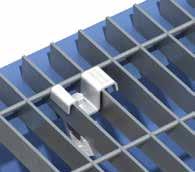
 Position pre-assembled Grate-Fast with the body between the grating bars and the nose pointing towards the steelwork.")
50 50 Floor Fixings by Lindapter Type GF - Grate-Fast A high strength floor fixing for rectangular open bar grating, providing superior clamping force due to a malleable iron cast body. Lloyd s Register Type Approval for resistance to shock and vibration. DECKING FIXINGS SUPPORT FIXINGS FLOOR FIXINGS HOLLO-BOLT LIFTING POINTS RAIL FIXINGS GIRDER CLAMPS Top Hat Bracket Cast Body GF08 for GRP grating with stainless steel top hat bracket, Sheraplex coated body and socket head screw. GF10HDG is hot dip galvanised for increased corrosion resistance. GF210HDG is hot dip galvanised for use with 30 width floor grating bars only. GF08 / GF10HDG D GF210HDG D min X max X X How to install... W W Hex Head Screw Product Bolt 8.8 1) Position pre-assembled Grate-Fast with the body between the grating bars and the nose pointing towards the steelwork. The arrows on the top hat bracket should also be pointing towards the supporting steelwork and the bracket itself resting on the bearing bars. 2) Slide the Grate-Fast towards the steelwork until the nose fits under the beam flange. Where necessary adjust body / screw to the approximate flange thickness / grating depth. 3) Tighten the screw. The Grate-Fast body will automatically rotate until it locks under the bearing bar, with the nose under the flange. Tighten to recoended torque. Flange T Grating Bar Depth D Grating Bar Width W Bar Distance Tightening Torque Note: For GF08 tighten the socket head cap screw with a 6 hexagon key. For GF10HDG and GF210HDG tighten the hex head screw using a torque wrench with a 10 A/F socket. Across Flats X Nm GF08 1) M GF10HDG 2) M GF210HDG 2) M ) Supplied with socket head cap screw. 2) Supplied with hex head screw. Watch the installation video at Material: Top Hat: Stainless steel grade 304 (GF08 only). Mild Steel, hot dip galvanised (GF10HDG and GF210HDG only). Body: Malleable iron, Sheraplex (GF08 only). Malleable iron, hot dip galvanised (GF10HDG and GF210HDG only) T +44 (0) Lindapter International 2016

 Insert the pre-assembled Type 1055 into the countersunk hole between the grating bars.")
 Use a 5 hexagon key to rotate the countersunk setscrew clockwise until the grating lug makes contact with the grating bar.")
51 Floor Fixings by Lindapter 51 Type 1055 This unique solution enables solid plate flooring to be fitted to open-mesh or open-grid flooring using simple hand tools. Plug A/F 8 Thread locking adhesive Grating Lug Material: Cast stainless steel, self colour. Product Bolt A4-70 Floorplate Thickness t Clamping Range C Grating Bar Width W Hole Ø d Countersunk Ø D Setscrew Tight. Torque Hex. Key Nm Nm Nm FG1055 M8 min How to install... Setscrew A/F 5 1) Insert the pre-assembled Type 1055 into the countersunk hole between the grating bars. 2) Use an 8 hexagon key to rotate the plug anti-clockwise until the underside of the plug locates against the grating bar. 3) Use a 5 hexagon key to rotate the countersunk setscrew clockwise until the grating lug makes contact with the grating bar. 4) Tighten the setscrew to 11Nm; the grating lug will be drawn up the screw and will activate the thread locking adhesive. Watch the installation video at Fast installation from above, no need for expensive scaffolding. Stainless steel for high corrosion resistance. Superior clamping force from high quality castings. Safely retrofit without welding, no need for hot work permits t 90 o D d W C GIRDER CLAMPS RAIL FIXINGS LIFTING POINTS HOLLO-BOLT FLOOR FIXINGS SUPPORT FIXINGS DECKING FIXINGS Lindapter International (0)

52 52 Support Fixings by Lindapter The Type F3 has a large clamping range to suit various flange thicknesses (see page 56). Support Fixings pages Easy-to-install connections for suspending building services from structural or secondary beams. Typical applications include supporting HVAC equipment, pipe work, fire protection and sprinkler systems. Adjustable to allow a fast and precise alignment of building services. Type FLS page 53 Type FL page 54 Type LC page 55 Type SW page 55 Type F3 page 56 Type SH page 57 Type HW/HC page 57 Purlin Clips page (0) Lindapter International 2016

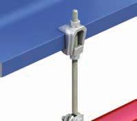
 Locate the FLS onto the flange.")
53 Support Fixings by Lindapter 53 Type FLS A versatile flange clamp with a swivel unit for inclined applications. Supplied with a high tensile setscrew for a secure grip on both parallel and tapered flanges. Setscrew T Locknut Lug Nut Nut Basket Material: High grade alloy steel, zinc plated. Product Rod Y Safe Working Load (4:1 Factor of Safety) Tensile 25 o Swivel Unit (M10 only) Tensile 25 o to 45 o Clamping Range W Setscrew Tightening Torque Setscrew Locknut N Dimensions R T U X Width kn kn Nm Nm FLS08 M M FLS10 M M Independently Approved Applications 25 How to install... N 1) Locate the FLS onto the flange. M 2) Ensuring the lug nut (M) locates into the main body, tighten down the setscrew () and locknut (N). 3) Install the threaded rod by screwing into the nut 1. S located in the nut basket (S). Ensure full thread capture. 4) Secure assembly in nut basket (S) from beneath using a nut (not supplied). Ensure that the cup point setscrew always grips on the tapered side of the flange. N W R Y X U General Applications (Parallel Flanges only) GIRDER CLAMPS RAIL FIXINGS LIFTING POINTS HOLLO-BOLT FLOOR FIXINGS SUPPORT FIXINGS DECKING FIXINGS Lindapter International (0)
 T Material: Malleable iron, zinc plated.")
 Tensile Clamping Range W 1) Slide the Type FL onto the beam flange and tighten setscrew to the recoended torque.")

54 54 Support Fixings by Lindapter Type FL FM and VdS approved flange clamp for use with parallel or tapered flange beams, supplied with the rear hole drilled or tapped. DECKING FIXINGS SUPPORT FIXINGS FLOOR FIXINGS HOLLO-BOLT LIFTING POINTS RAIL FIXINGS GIRDER CLAMPS Rear Hole (drilled or tapped) T Material: Malleable iron, zinc plated. Product Clear Tapped Clear Hole Ø Y V How to install... W X Tapped Thread Y Hexagon Setscrew Locknut Safe Working Load (4:1 FOS) Tensile Clamping Range W 1) Slide the Type FL onto the beam flange and tighten setscrew to the recoended torque. As a guide, tighten the setscrew finger tight and then apply an additional quarter turn (90 ) with spanner. 2) Tighten the locknut (N) to the recoended torque. On tapered flanges, the cup point setscrew has to grip on the inside of the flange. N Y Setscrew Tightening Torque Setscrew Locknut N Dimensions T U X Width V kn Nm Nm FL106D FL106T 7 M M FL108D FL108T 9 M M FL210D FL210T 11 M M1O FL312D FL312T 13 M M FL412D FL410T 13 M M The Type FL can be used with Type SW (page 55) when connecting to inclined sections. U (M10 and M12 only) (0) Lindapter International 2016


55 Support Fixings by Lindapter 55 Type LC A flange clamp for parallel or tapered flanges with tapped holes to accept threaded rod or cable clips. Supplied with a high tensile cup point setscrew. Locknut Setscrew Material: Malleable iron, zinc plated. Product Thread Main Body X Y Tensile in Position X Type SW A swivel unit for applications on inclined beams complete with a M10 x 90 (property class 8.8) setscrew and nut. Can be supplied with Type FL or Type 10. Material: High grade alloy steel, zinc plated. Product T Safe Working Load (4:1 Factor of Safety) Tensile in Position Y Safe Working Load (4:1 FOS) Clamping Range W Rod Tensile Maximum Inclination Setscrew Rotation Tightening Torque Setscrew Tightening Torque Locknut N Dimensions T U Width V kn kn Nm Nm LC06 M6 M M LC08 M8 M M R V V W U Y N X U Installation is the same as Type FL (page 54). Type FL (page 54) Type 10 (page 58) Dimensions (when used with Type FL) U R Width with Bolt V kn Nm SW10 M o 360 o GIRDER CLAMPS RAIL FIXINGS LIFTING POINTS HOLLO-BOLT FLOOR FIXINGS SUPPORT FIXINGS DECKING FIXINGS Lindapter International (0)

 Tensile Clamping Range W Tightening Torque Dimensions S T V X Width R kn Nm F308NC F308NB M8 0.9 2-25 6 19 6 8 20 33 F310NC F310NB M10 1.")
56 56 Support Fixings by Lindapter Type F3 An FM approved, high strength flange clamp with a large clamping range. Compatible with drop rods and J bolts. DECKING FIXINGS SUPPORT FIXINGS FLOOR FIXINGS HOLLO-BOLT LIFTING POINTS RAIL FIXINGS GIRDER CLAMPS Nut V W V With Bolt R Product Without Bolt Bolt 4.6 Bolt For heavier loads or wider clamping range, please see the Type F9 on page 24. Material: Malleable iron, hot dip galvanised. X T S Safe Working Load (4:1 Factor of Safety) Tensile Clamping Range W Tightening Torque Dimensions S T V X Width R kn Nm F308NC F308NB M F310NC F310NB M F312NC F312NB M F316NC F316NB M F320NC F320NB M For parallel flanges only. Supplied with or without bolt. +44 (0) Lindapter International 2016


57 Support Fixings by Lindapter 57 Type SH A strap hanger with LPCB and FM approval for use in fire sprinkler installations. Supplied with or without a hanger nut. Can be used with all Lindapter flange clamps. Hanger Nut With Hanger Nut Material: Pre-galvanised strip. WITHOUT HANGER NUT Pipe Bore LPS1194 Issue 1.2 Certificate No. 1171a (25-50 Pipe Bore only) Rod Hole Ø SH M8 or M10 11 SH M8 or M10 11 SH M8 or M10 11 SH M8 or M10 11 SH M8 or M10 11 SH M8 or M10 11 SH M8 or M10 11 SH M12 13 SH M12 13 SH M16 18 Type HW / HC For vertical suspension on angled surfaces of up to 10 swing either side of the vertical. Washer Cup W2 Material: Malleable iron, zinc plated / hot dip galvanised. X R Y W1 L WITH HANGER NUT Product Hemispherical Washer Hemispherical Cup Hemispherical Washer & Cup Hemispherical Hemispherical Rod X W1 Y W2 R L Washer Cup (can be used without cup) HW10 HC10 M HW12 HC12 M HW16 HC16 M HW20 HC20 M Pipe Bore Rod Hole Ø SH025N 25 M8 or M10 14 SH032N 32 M8 or M10 14 SH040N 40 M8 or M10 14 SH050N 50 M8 or M10 14 SH065N 65 M8 or M10 14 SH080N 80 M8 or M10 14 SH100N 100 M8 or M10 14 SH125N 125 M12 17 SH150N 150 M12 17 SH200N 200 M o GIRDER CLAMPS RAIL FIXINGS LIFTING POINTS HOLLO-BOLT FLOOR FIXINGS SUPPORT FIXINGS DECKING FIXINGS Lindapter International (0)
.")
 Purlins Rod Tensile Tightening Torque kn Nm 10 Kingspan Multibeam 2 & 3 How to install... M10 0.2 8 10 Metsec M10 0.1-0.")
58 58 Support Fixings by Lindapter Type 10 A purlin clip designed to suit a large range of purlin sections. Can be used with the Type SW for use on inclined purlins (see page 55). DECKING FIXINGS SUPPORT FIXINGS FLOOR FIXINGS HOLLO-BOLT LIFTING POINTS RAIL FIXINGS GIRDER CLAMPS Material: Mild steel, zinc plated. Safe Working Load (3:1 FOS) Purlins Rod Tensile Tightening Torque kn Nm 10 Kingspan Multibeam 2 & 3 How to install... M Metsec M eta M Safe working loads are subject to the strength of the purlin. Please refer to the purlin manufacturer s literature (0) Lindapter International 2016


59 Support Fixings by Lindapter 59 Type HCW30 A purlin clip suitable for horizontal purlins. Material: Pre-galvanised strip. Safe Working Load (3:1 FOS) Purlin Rod Tensile Tightening Torque kn Nm HCW30 Kingspan Multibeam 3 M Safe working loads are subject to the strength of the purlin. Please refer to the purlin manufacturer s literature. Type HCW31 A universal purlin clip suitable for multiple applications. Material: Pre-galvanised strip. Safe Working Load (3:1 Factor of Safety) Purlin Tensile kn HCW31 Kingspan Multibeam Safe working loads are subject to the strength of the purlin. Please refer to the purlin manufacturer s literature. How to install GIRDER CLAMPS RAIL FIXINGS LIFTING POINTS HOLLO-BOLT FLOOR FIXINGS SUPPORT FIXINGS DECKING FIXINGS Lindapter International (0)
 Rod Tensile Max. Purlin Thick.")
 must decrease.")
60 60 Support Fixings by Lindapter Type WF The Webfix allows a quick installation directly from the web of ed purlins. DECKING FIXINGS SUPPORT FIXINGS FLOOR FIXINGS HOLLO-BOLT LIFTING POINTS RAIL FIXINGS GIRDER CLAMPS Material: Mild steel, zinc plated. Prod. Safe Working Load (5:1 FOS) Rod Tensile Max. Purlin Thick. Hole Ø Max Distance X at Angle of 10 O 20 O 30 O kn WF10 M Hole Position for Canted Purlins When purlins are connected to a sloping roof beam, the maximum allowable distance X (hole centre to bottom edge of the purlin) must decrease. X Hole Position of Inclined Purlin Type WF adjusts to whatever angle is required. Hole position is not a limiting factor on product installation. X How to install... 1) Squeeze the legs of the Type WF together and push through the hole until it clicks into place. 2) Assemble with the nut, ensuring full thread capture (0) Lindapter International 2016


 Type FL (page 54) Type HCW30")
 Type WF (page 60) GIRDER CLAMPS")

61 Support Fixings by Lindapter 61 Typical Applications for Support Fixings Examples of popular connection arrangements are shown below. Visit to view more examples or contact Lindapter to discuss your connection requirement. Type FLS (page 53) Type FL (page 54) Type HCW30 Type 10 Type SH Types SH, 10 + HCW30 (pages 57-59) Type F3 (page 56) Type WF (page 60) GIRDER CLAMPS RAIL FIXINGS LIFTING POINTS HOLLO-BOLT FLOOR FIXINGS SUPPORT FIXINGS DECKING FIXINGS Lindapter International (0)


62 62 Decking Fixings by Lindapter Decking Fixings pages High quality, cost effective connections for securing building services. Designed to fit inside the dovetail re-entrant channels of popular composite decking profiles, Lindapter s fixings provide a zero-impact method that avoids delamination and damage to the decking. On-site pull tests Lindapter s Engineers can provide tensile tests on the full range of decking fixings. Available on request and subject to application. +44 (0) Lindapter International 2016
,")

 TR60+ and TR80+ Composite Metal Flooring (CMF )")
 Ribdeck E60 Tata Steel Europe ComFlor 225 Fits several profiles including: R51")
 and MetFloor 55 (CMF ) Compatible Composite Decking Profile(s) Designed for: Service suspension from")

63 Decking Fixings by Lindapter 63 Product Comparison The table below shows the various components that are designed to fit the decking profiles of major manufacturers such as Composite Metal Flooring (CMF ), Kingspan Structural Products and Structural Metal Decks (SMD). Components Lindapter Decking Fixing Type TR60 page 64 Type MF page 65 Type MW2 - Multiwedge 2 page 66 Type AW - Alphawedge page 67 Type SD2 - Slimdek 2 page 68 Type VN page 69 Also available Type TC - Toggle Clamp page 69 Structural Metal Decks (SMD) TR60+ and TR80+ Composite Metal Flooring (CMF ) MetFloor 60 and MetFloor 80 Kingspan Structural Products Multideck 60 and Multideck 80 Hare Decking (formerly Richard Lees ) Ribdeck E60 Tata Steel Europe ComFlor 225 Fits several profiles including: R51 (SMD), ComFlor 51 (Tata Steel ), Holorib (Hare Decking), Superib (Hare Decking), Multideck 50 (Kingspan ) and MetFloor 55 (CMF ) Compatible Composite Decking Profile(s) Designed for: Service suspension from pre-cast hollow core slabs (minimum core depth of 75) as well as Structural Hollow Section (SHS), steel sheeting or purlins. GIRDER CLAMPS RAIL FIXINGS LIFTING POINTS HOLLO-BOLT FLOOR FIXINGS SUPPORT FIXINGS DECKING FIXINGS Lindapter International (0)

64 64 Decking Fixings by Lindapter Type TR60 Designed for the TR60+ and TR80+ profiles manufactured by Structural Metal Decks (SMD). Wedge DECKING FIXINGS SUPPORT FIXINGS FLOOR FIXINGS HOLLO-BOLT LIFTING POINTS RAIL FIXINGS GIRDER CLAMPS Locking Plate Locking Plate: Pre-galvanised strip. Wedge: Malleable iron, bright zinc plated. How to install... Safe Working Load (3:1 FOS) Product Rod min 4.6 Tensile / 1 Rod Tightening Torque kn Nm TR6006 M TR6008 M TR6010 M ) Pre-assemble the locking plate and wedge (flat surface up) onto the threaded rod. 2) Insert the wedge into the re-entrant channel of the decking. 3) Rotate until the chamfered cams engage on the sides of the channel. 4) Slide the plate up the threaded rod and over the wedge to lock it into position in the channel. Tighten the locknut beneath the plate to hold the assembly in position. Install the decking fixings after the concrete has been poured and has reached full strength. Watch the installation video at If the decking profile is deformed or distorted, do not install the fixing. If in doubt, contact the Technical Support team for advice. +44 (0) Lindapter International 2016
 Product Rod min 4.")
, it should NOT be used in profiles manufactured by Kingspan Structural Products. 1. 2. 3. 4.")
65 Decking Fixings by Lindapter 65 Type MF Specifically developed for use with MetFloor 60 and MetFloor 80 profiles manufactured by Composite Metal Flooring (CMF ). Wedge Bracket Bracket: Steel strip, zinc plated + JS500 Wedge: Malleable iron, zinc plated. How to install... Safe Working Load (3:1 FOS) Product Rod min 4.6 Tensile / 1 Rod Tightening Torque kn Nm MF06 M MF08 M MF10 M Although the Type MF is similar in appearance to the Type MW2 (page 66), it should NOT be used in profiles manufactured by Kingspan Structural Products ) Pre-assemble the bracket and wedge (flat surface facing up) onto the threaded rod and insert one side of the bracket into the re-entrant channel of decking. 2) Insert the other side of the bracket into position inside the decking. 3) Turn the wedge clockwise until the position in Fig. 4 has been achieved. 4) Tighten the nut on the rod to a torque of 10Nm (prevent rod from rotating). Install the decking fixings after the concrete has been poured and has reached full strength. If the decking profile is deformed or distorted, do not install the fixing. If in doubt, contact the Technical Support team for advice. GIRDER CLAMPS RAIL FIXINGS LIFTING POINTS HOLLO-BOLT FLOOR FIXINGS SUPPORT FIXINGS DECKING FIXINGS Lindapter International (0)

, it should NOT be used in profiles manufactured by CMF.")
66 66 Decking Fixings by Lindapter Type MW2 - Multiwedge 2 Designed for the Multideck 60 and Multideck 80 profiles manufactured by Kingspan Structural Products. Wedge DECKING FIXINGS SUPPORT FIXINGS FLOOR FIXINGS HOLLO-BOLT LIFTING POINTS RAIL FIXINGS GIRDER CLAMPS Bracket Bracket: Pre-galvanised strip. Wedge: Malleable iron, bright zinc plated. How to install... Safe Working Load (3:1 FOS) Product Rod min 4.6 Tensile / 1 Rod Tightening Torque kn Nm MW06 M MW08 M MW10 M Install the decking fixings after the concrete has been poured and has reached full strength. Although the Type MW2 is similar in appearance to the Type MF (page 65), it should NOT be used in profiles manufactured by CMF. 1) Pre-assemble the bracket and wedge (flat surface facing up) onto the threaded rod and insert one side of the bracket into the re-entrant channel of the decking. 2) Click the other leg of the bracket into position inside the decking and slide the assembly to the desired position along the length of the re-entrant channel. 3) Push and turn the wedge clockwise until it locks into the channel walls. 4) Tighten the hexagon nut beneath the assembly. If the decking profile is deformed or distorted, do not install the fixing. If in doubt, contact the Technical Support team for advice. +44 (0) Lindapter International 2016
 Product Rod min 4.")
 Insert the wedge into the re-entrant channel of the decking and rotate 90. 3) Slide the plate up the threaded rod, over the wedge, to lock it in position into the channel.")
67 Decking Fixings by Lindapter 67 Type AW - Alphawedge Designed for Ribdeck E60 profiles manufactured by Hare Decking (formerly Richard Lees ). Wedge Locking Plate Locking Plate: Pre-galvanised strip Wedge: Malleable iron, zinc plated. How to install... Safe Working Load (3:1 FOS) Product Rod min 4.6 Tensile / 1 Rod Tightening Torque kn Nm AW06 M AW08 M AW10 M ) Pre-assemble the locking plate and wedge (flat surface up) onto the threaded rod. 2) Insert the wedge into the re-entrant channel of the decking and rotate 90. 3) Slide the plate up the threaded rod, over the wedge, to lock it in position into the channel. 4) Tighten the locknut beneath the plate to hold the assembly in position. Install the decking fixings after the concrete has been poured and has reached full strength. If the decking profile is deformed or distorted, do not install the fixing. If in doubt, contact the Technical Support team for advice. GIRDER CLAMPS RAIL FIXINGS LIFTING POINTS HOLLO-BOLT FLOOR FIXINGS SUPPORT FIXINGS DECKING FIXINGS Lindapter International (0)
 Product Rod min 4.")
 With Slimdek 2 (SD2) in its retracted position (as supplied) locate the fixing in the re-entrant channel.")
 Tighten the cam nut until the inner body of the fixing locates against the re-entrant channel. 4) Offer the V-Nut on a threaded rod up to the main body.")
68 68 Decking Fixings by Lindapter Type SD2 - Slimdek 2 Designed for the ComFlor 225 profiles manufactured by Tata Steel Europe, the Type SD2 offers a fully flexible suspension position. DECKING FIXINGS SUPPORT FIXINGS FLOOR FIXINGS HOLLO-BOLT LIFTING POINTS RAIL FIXINGS GIRDER CLAMPS V-Nut Inner Body Material: Pre-galvanised strip. Safe Working Load (3:1 FOS) Product Rod min 4.6 Tensile / 1 Rod Tightening Torque kn Nm SD210 M How to install... Cam Main Body Cam Nut Watch the installation video at 1) With Slimdek 2 (SD2) in its retracted position (as supplied) locate the fixing in the re-entrant channel. 2) Hold SD2 in position with one hand, then rotate the cam nut in the direction shown above with a spanner. 3) Tighten the cam nut until the inner body of the fixing locates against the re-entrant channel. 4) Offer the V-Nut on a threaded rod up to the main body. 5) Rotate the V-Nut through 90 to allow it to sit at the bottom of the SD2 body. 6) Secure the assembly with a nut. Install the decking fixings after the concrete has been poured and has reached full strength. If the decking profile is deformed or distorted, do not install the fixing. If in doubt, contact the Technical Support team for advice. +44 (0) Lindapter International 2016
 Product Rod min 4.6 Tensile / 1 Rod Tightening Torque kn Nm VN10 M10 2.")
 Screw V-Nut (VN) onto threaded rod. 2) Insert VN and rod into decking channel.")
69 Decking Fixings by Lindapter 69 Type VN Fits inside the re-entrant channel of several composite floor decking profiles including R51, Comflor 51, Holorib, Superib, Multideck 50 and MetFloor Material: Mild steel, zinc plated. Safe Working Load (4:1 FOS) Product Rod min 4.6 Tensile / 1 Rod Tightening Torque kn Nm VN10 M Type TC - Toggle Clamp Designed for service suspension from pre-cast hollow core slabs (minimum core depth 75) as well as SHS, steel sheeting or purlins. Material: Steel strip, zinc plated. How to install... 1) Screw V-Nut (VN) onto threaded rod. 2) Insert VN and rod into decking channel. 3) Rotate rod and VN through 90 so that the tapered edges engage the sides of the re-entrant channel. Safe Working Load (4:1 FOS)* Dimensions Product Rod min 8.8 Hole Ø Tensile / 1 Rod Tightening Torque T W Width V kn Nm TC08 M TC10 M How to install Install the decking fixings after the concrete has been poured and has reached full strength. If the decking profile is deformed or distorted, do not install the fixing. If in doubt, contact Technical Support for advice. 1) Pre-assemble the fixing on the rod and insert into the hole (ensure it is central to the hollow core). 2) Shake the rod to allow the toggle body to locate horizontally across the hole, then lower the rod so that the nut locates in the toggle body. 3) Wind up the rod to the top of the section so it is as high as possible. Secure the assembly with a nut and washer. T 12 V W * Subject to the strength of the concrete section GIRDER CLAMPS RAIL FIXINGS LIFTING POINTS HOLLO-BOLT FLOOR FIXINGS SUPPORT FIXINGS DECKING FIXINGS Lindapter International (0)


70 70 Project Case Studies Proven connection solutions Lindapter products are used in multiple industries around the world in an extensive range of applications. The case studies below highlight the wide use of Lindapter fixings. To view more project examples, please visit the website Tower Bridge, UK Birmingham New Street, UK Product: Type A Application: Type A clamps were used to attach the supporting steel frame of the new glass walkway to the original steel lattice. The new viewing platform spans 42m on the upper level of the bridge over the River Thames and features a glass floor to reveal the bridge deck and water below. The floor consists of six 80 thick glass panels, each weighing 530kg and supported by a 1000kg carbon steel framework. Lindapter s simple connection solution allowed the frame to be safely secured to the original steel lattice structure without on-site drilling or welding, ensuring that there was no damage to the bridge. The contractors completed the renovation inside six weeks without closing the site. Product: Type TR60 Application: Suspending building services in the concourse and John Lewis store. The 750 million redevelopment of Birmingham New Street and Grand Central building required a method for suspending building services in the John Lewis store and the railway station concourse. Lindapter TR60 s quickly slotted into the dovetail shaped re-entrant channel of the metal decking, allowing a quick and easy installation of mechanical and fire protection systems without the need for on-site drilling or welding. Installation only required the use of simple hand tools, saving time and labour costs as well as ensuring there was no damage to the decking. See page 8 for Type A. See page 64 for Type TR (0) Lindapter International 2016


71 Project Case Studies 71 History Museum, Dresden, Germany Hitachi Ashford Depot, UK Product: Type HB Stainless Steel Application: Securing steel façade panels to the structural steel hollow section. The Lindapter Hollo-Bolt secured steel cladding panels to the structural steel hollow section in Daniel Libeskind s impressive five storey façade, allowing the arrow shaped extension, made from glass, concrete and steel, to intersect the original neo-classical arsenal building. Contractors used over 2,000 M8 stainless steel Hollo-Bolts to quickly install the panels from just one side, avoiding on-site drilling or welding. The discreet Hollo-Bolts were manufactured from grade 316 stainless steel for enhanced corrosion resistance. Hufton & Crow Hufton & Crow Product: Type HD Application: Securing low speed rails to way beams in a train maintenance depot. Lindapter s M20 Type HD rail clips were used to connect low speed lines at Hitachi s Ashford Train Maintenance Centre. The product allowed contractors to safely secure FB rails along lengths of UKC way beam, in turn supported by reinforced concrete plinths. These low speed rails were installed in pairs down the entire length of the new depot building to give access for maintenance and repair work on the trains. Type HD facilitated the precise rail alignment by allowing a high degree of lateral adjustability. Image approved for use under by See pages for Hollo-Bolt. See pages for Type HD. Lindapter International (0)


 from sloped beams at the Splott Warehouse required a safe rigging unit that would provide resistance to both")


72 72 Project Case Studies Proven connection solutions Lindapter products are used in multiple industries around the world in an extensive range of applications. The case studies below highlight the wide use of Lindapter fixings. To view more project examples, please visit the website Splott Warehouse, Cardiff, UK St Pancras Station, London, UK Product: Type ALP Application: Rigging lighting equipment to the overhead structural beams at the Color Festival. Securing equipment weighing 6.3kN (642kg) from sloped beams at the Splott Warehouse required a safe rigging unit that would provide resistance to both tensile and frictional loading. The Type ALP was chosen because it has a safe working load of 3 tonnes at an angle +/- 18 and adjusts to various beam sizes, meaning one type of rigging unit could be used throughout. After the dance festival finished, the contractors simply reversed the installation procedure, which allowed them to quickly unclamp the lifting system without damaging the steel beams. Product: Type AF Application: Connecting the steel framework of a new roof to the station s existing structure. The Type AF allowed a new steel framed roof to be secured to the existing structure of the Grade I listed shed designed by William Henry Barlow at St Pancras Station. The product accoodated variations in height due to sagging in some areas of the original riveted beam structure, ensuring a secure load at varying angles. Lindapter s high slip resistance clamp assembly avoided drilling or welding, thereby removing the risk of damaging the historic Victorian arches and the protective coatings. Robert Lordan See page 36 for Type ALP. See page 14 for Type AF. +44 (0) Lindapter International 2016


73 Project Case Studies 73 Manhattan Bridge, New York, USA Arnside Viaduct, UK Network Rail Product: Type F3 Application: Securing 450m pipework carrying an internet cable along the bridge. Lindapter Support Fixings are often specified for securing pipework due to the ease of installation and high adjustability. In this case, the Type F3 was used to connect a 100 pipe, carrying fibre optic cable for high-speed internet across this iconic structure. Using simple hand tools avoided on-site drilling and welding meaning that there was no need for hot work permits or a site closure. This simplified the installation across the span of the iconic bridge and allowed the contractors to finish on time and on budget. Product: Type FF - FloorFast Application: Securing the maintenance walkway alongside the replacement viaduct deck. An upgrade of the 150 year old viaduct required the replacement of the entire deck. Chequer plate flooring was quickly secured to supporting box girder sections along the entire length of the new deck using 8,000 of Lindapter s easy to install FloorFast fixings. FloorFast allows installation to be easily carried out from above, without the need for drilling, welding or scaffolding. This meant the flooring could be fitted on the viaduct as the deck units were removed, helping the major renovation to be completed on schedule. See page 56 for Type F3. See page 49 for Type FF - FloorFast. Lindapter International (0)


74 74 Independent Approvals Passionate about safety For over 80 years, Lindapter has manufactured to the highest standards, earning a multitude of independent approvals and a reputation synonymous with safety and reliability. Current accreditations are detailed below. Independent Product Approvals These approvals reinforce Lindapter s extensive in-house testing procedures. Products are tested so that Engineers and Contractors can be confident Lindapter products will perform as detailed in this catalogue. CE Mark For Lindapter products in compliance with provisions of the EC Construction Product Regulation 305/2011/EU, please refer to /About/CE Lloyd s Register Type Approval Lloyd s Register Type Approved products have been subjected to tensile, frictional, vibration and shock tests, witnessed and verified by Lloyd s Register. Deutsches Institut für Bautechnik DIBt approves construction products for use in structural and civil engineering industries in Germany. Verband der Schadenversicherer VdS is a leading independent testing institution in Germany for products used in fire protection applications. Factory Mutual This American insurance organisation offers an approval that is recognised by the fire protection industry worldwide. Loss Prevention Certification Board The LPCB is a leading International Certification body in the field of security and fire protection. TÜV Nord TÜV is the certifying authority for safety, quality and environmental protection in Germany. ICC ICC-ES Lindapter s Hollo-Bolt has been approved for use in Seismic Design Categories (SDC) A through F by North America s leading evaluation service. Quality and Environment Accredited to ISO 9001 since 1986, Lindapter strictly enforces a quality management system that includes vigorous product testing to ensure consistently high manufacturing standards. The company also operates an ISO certified environmental management system, constantly monitoring and improving aspects of the business that may impact on the environment, such as the use of natural resources as well as handling and treatment of waste and energy consumption. Q EMS Associations Lindapter is a member of the British Constructional Steelwork Association (BCSA), The Steel Construction Institute (SCI), American Institute of Steel Construction (AISC), Southern African Institute of Steel Construction (SAISC) and the Australian Steel Institute (ASI). Factory Production Control and Traceability The company operates a fully documented Factory Production Control system ensuring full compliance and traceability throughout the manufacturing process, in conjunction with the Construction Products Regulation. +44 (0) Lindapter International 2016


75 Here to help you Lindapter s team of experienced Engineers offer an unrivalled support service, including free connection design and bespoke product development. Lindapter s philosophy is to deliver the highest level of service from initial design through to installation guidance. Technical Support 75 The Lindapter Service includes: 3D Free design proposal 2D / 3D drawings Quotation Global distribution Installation guidance FREE CONNECTION DESIGN Contact Lindapter s team of experienced Engineers and they will advise a suitable solution for you free of charge, providing drawings in 2D or interactive 3D formats as well as CAD files that can be imported into all major software applications. Provide the details below and Lindapter will do the rest! Steel sizes to be used or flange width / thickness Loads to be resisted (e.g. 10kN tension + 15kN slip) General arrangement sketch or verbal description Project Name / Title / Location (optional) ENGINEERED SOLUTIONS Lindapter s Research & Development facility and unique expertise facilitates a bespoke product development service, passionately referred to as Engineered Solutions. Supported by the latest technology including 3D modelling, rapid prototyping with the aid of two in-house 1,000kN hydraulic test machines and finite element analysis, Lindapter s Engineers can develop solutions that satisfy your connection demands. Contact Lindapter to design a solution to your connection requirements. support@lindapter.com or call +44 (0) for more details. Disclaimer Lindapter International supplies components in good faith, on the assumption that customers fully understand the loadings, safety factors and physical parameters of the products involved. Customers or users who are unaware or unsure of any details should refer to Lindapter International before use. Responsibility for loss, damage, or other consequences of misuse cannot be accepted. Lindapter makes every effort to ensure that technical specifications and other product descriptions are correct. Specification shall mean the specification (relating to the use of the materials) set out in the quotation given by the Seller to the Buyer. Responsibility for errors or omissions cannot be accepted. All dimensions stated are subject to production tolerances - if in doubt please check with Lindapter. In the interests of improving the quality and performance of Lindapter products, we reserve the right to make specification changes without prior notice. Lindapter International 2016 LINDAPTER, HOLLO-BOLT, LINDIBOLT, LINDICLIP, FLOORFAST, GRATE-FAST etc., are all registered trademarks. Lindapter may also have trademark rights in other terms used herein. Lindapter International (0)
 1274 521130 E: enquiries@lindapter.com support@lindapter.")
76 Lindsay House Brackenbeck Road Bradford West Yorkshire BD7 2NF United Kingdom T: +44 (0) F: +44 (0) E: LindUKJan16
Available from. Established Technical Innovation in Steelwork Connections
 Established 1934 Technical Innovation in Steelwork Connections 2 Introduction to Lindapter Welcome For over 80 years Lindapter has earned a respected reputation as the pioneer in the design and manufacture
Technical Innovation in Steelwork Connections
 Technical Innovation in Steelwork Connections Established 1934 Lindapter - Technical Innovation in Steelwork Connections 2 For more than 75 years, Lindapter has earned a respected reputation as the inventor
Steel Floor Connections
 Steel Floor Connections Pioneering high strength steel connections since 1934 2 Steel Floor Connections by Lindapter Welcome For over 80 years Lindapter has earned a respected reputation as the pioneer
Technical Innovation in Steel Connections
 Technical Innovation in Steel Connections USA & Canada Catalog Established 1934 Lindapter - Technical Innovation in Steel Connections 2 inquiries@lindapterusa.com www.lindapterusa.com For more than 75
Hollo-Bolt. High Clamping Force (HCF) M8 M10 M12 M16 M20 JS500 Stainless Steel Sheraplex Hot Dip Galv.
 M8 M10 M12 M16 M20 JS500 Stainless Steel Sheraplex Hot Dip Galv.") Type HB - Hollo- Type HB - Hollo- Steel, bright zinc plated plus JS5 Steel, sheraplex Steel, hot dip galvanised (Hex Head only) Stainless Steel Grade 316 Hollo- Suitable for hollow sections, tubes and
Type HB - Hollo- Type HB - Hollo- Steel, bright zinc plated plus JS5 Steel, sheraplex Steel, hot dip galvanised (Hex Head only) Stainless Steel Grade 316 Hollo- Suitable for hollow sections, tubes and
Tel: +44 (0)
") 4 Lindapter s support fixing range offers a series of ideal solutions for all building services. This includes the suspension of HVAC equipment, pipe work, fire protection/sprinkler systems, suspended
4 Lindapter s support fixing range offers a series of ideal solutions for all building services. This includes the suspension of HVAC equipment, pipe work, fire protection/sprinkler systems, suspended
Cone. Bolt. Rubber Washer. Rubber Washer. compressed / increased clamping force
 Type HB - Hollo-Bolt Cavity Fixings 2 Type HB - Hollo-Bolt Steel, bright zinc plated plus JS 500 Steel, hot dip galvanised Stainless Steel Grade 316 Collar Sleeve Cone Bolt Suitable for hollow sections,
Hollo-Bolt. The Original Expansion Bolt for Structural Steel ALLFASTENERS. Your trusted Australian supplier. Available
 Available WWW.ALLFASTENERS.COM.AU ALLFASTENERS. The Original Expansion Bolt for Structural Steel Now marked Hollo-Bolt by 2 WELCOME Call 1800 255 349 THE ORIGINAL EXPANSION BOLT FOR STRUCTURAL STEEL Lindapter,
The Original Expansion Bolt for Structural Steel. Hollo-Bolt
 The Original Expansion Bolt for Structural Steel Now marked by 2 WELCOME THE ORIGINAL EXPANSION BOLT FOR STRUCTURAL STEEL Lindapter, the steelwork connection specialists, invented the as a fast, cost effective
STEEL CONSTRUCTION FASTENERS STEEL CONSTRUCTION FASTENERS
 STEEL CONSTRUCTION FASTENERS STEEL CONSTRUCTION FASTENERS 1 STEEL CONSTRUCTION FASTENERS 2 STEEL CONSTRUCTION FASTENERS Contents New Construction Products Regulation (CPR) 5 1. High strenght structural
Products for fixing to Steelwork and Decking
 Products 8.0 Beam Clamp - Single Support 8.1 Universal Joint for any variable Angle Adjustment 8.2 Beam Clamp TCS for Header Rails 8.3 Beam Clip for Cross Support/ Dimensioning of Bolts 8.4 Beam Clip for
Simotec. 13.i
 Products: Framo 80 13.0 Products: Framo 80 13.1 Products: Structural Elements 100/120 13.2 Products: Pipe Shoes 13.3 Framo 80: Beam Section and Screw 13.4 Framo 80: Cantilever Bracket and End Support STA
BEST PRACTICE GUIDE. Socket Bases. Working with Concrete Slabs
 Working with Concrete Slabs When working with concrete slabs the barrier protection can be erected in three ways - with socket bases, adjustable slab edge brackets and multi slab clamps. Socket Bases 1
Composite Decking Fixings 3
 Composite Decking Fixings 3 Composite Decking Fixings Lindapter composite decking fixings have all been designed in conjunction with the various decking manufacturers to ensure they fulfil the necessary
Adjustable Feet Castors Accessories for Floor Elements
 Adjustable Feet Castors Accessories for Floor Elements Products in this section Levelling Knuckle Feet Threaded spindles for infinite height adjustment Metal or plastic foot plate Knuckle Feet X Compatible
5/16" Flange nut. Bolt Keeper Plate (8" Sq. SYS.) (3) 1/2" x 3" Hex head connector zinc plated bolt w/ washers and nut. Anchor 3" sq. 7 Ga.
 (3) 1/2 x 3 Hex head connector zinc plated bolt w/ washers and nut. Anchor 3 sq. 7 Ga.") 2 1/2" x 2 1/2" x 10 Ga. 6" 5" 4" Variable Slipbase (8" Sq. SYS.) 5/16 Corner Bolt W/ nut 5/16" Flange nut Stub Insert (8" Sq. SYS.) Bolt Keeper Plate (8" Sq. SYS.) (3) 1/2" x 3" Hex head connector zinc
2 1/2" x 2 1/2" x 10 Ga. 6" 5" 4" Variable Slipbase (8" Sq. SYS.) 5/16 Corner Bolt W/ nut 5/16" Flange nut Stub Insert (8" Sq. SYS.) Bolt Keeper Plate (8" Sq. SYS.) (3) 1/2" x 3" Hex head connector zinc
Khathij Industrial Fasteners
 Dear Sir/Madam, Khathij Industrial Fasteners This is Saqubar Sadique representing 'KHATHIJ INDUSTRIAL FASTENERS' from Chennai, India. We 'Khathij industrial fasteners' like to introduce us as a Stockist
Swifts cable ladder supports
 heavy duty cantilever arms Heavy duty cantilever arms enable horizontal runs of cable ladder to be mounted to vertical steel, concrete or masonry surfaces or to Swiftrack channel. They are suitable for
MEFA mounting accessories
 MEFA mounting accessories Mounting accessories Base plates Page 5/2 Double holder Page 5/4 Height-adjustable suspensions Page 5/5 Pendular bolt joints Page 5/6 Trapeze hanger Page 5/7 Threaded hooks, distance
Notes. Modifications and constructional corrections arising particularly from technological development excepted.
 Notes Our service staff and application en gineers will be pleased to offer you their assistance to answer your questions or to work out in cooperation with you specific solutions with the aid of our own
PENSTOCK VALVES. Performance through Excellence
 VALVES & MANUFACTURING (1988) LTD. PENSTOCK VALVES Performance through Excellence SLIDEGATES WEIR GATES STOP LOGS SLIDEGATES PRECISION FACE SEALING VALVES WEIR GATES STOP LOGS SLIDEGATES Actuation Installation
The Original Expansion Bolt for Structural Steel. Hollo-Bolt
 The Original Expansion Bolt for Structural Steel Hollo-Bolt 2 WELCOME THE ORIGINAL EXPANSION BOLT FOR STRUCTURAL STEEL Lindapter, the steel connection specialists, invented the Hollo-Bolt as a fast, cost
MPA-9000 Universal Ceiling Projector Mount Kit
 I N S T R U C T I O N M A N U A L Universal Ceiling Projector Mount Kit The Universal Ceiling Projector Mount provides a unique, simplified method of ceiling mounting your inverted projector. This low
PUSH-PULL-PROPS. and accessories ROBUSTA-GAUKEL GMBH MOUNTING TECHNOLOGY &CO.KG
 PUSH-PULL-PROPS and accessories MOUNTING TECHNOLOGY ROBUSTA-GAUKEL GMBH &CO.KG MOUNTING TECHNOLOGY PUSH-PULL-PROPS AND ACCESSORIES INDEX General information...................... 3 Push-pull-prop Type
Clamping devices 521
 Clamping devices 521 522 Product overview Clamping devices Adjustable straps K0001 Hook clamps K0012 Goose-neck straps with long slot K0002 Page 526 Hook Clamps with collar K0013 Page 535 Equipped clamps
Pole Mount Installation Manual
 Pole Mount Installation Manual Thank You for Choosing AIMS Power! 1. AIMS Power is a leading supplier of solar products, specializing in PV mounting systems. We ensure our products are manufactured to
Optimast Installation Method Statement. F108.
 Optimast Installation Method Statement. F108. Contents Page 1) Product Description. 2) Durability....... 3) Profile & Baseplate..... 4) Anchor Cradle and Foundation Stud Set Detail Drawings 4a) 127...
PEC-TA Cast-in Channels and Bolts. Certified German quality for high-end fixing solutions. Advantages of using PEC Cast-in Channels.
 Fixing Technology s and Bolts PEC Cast-in Channels are ideally suited for quick, reliable and cost-efficient fixing of different construction elements. The possibility of making simple and flexible adjustments
Roller Guides C-Rail Systems Linear Guide Systems Ball-Bearing Guide Bushes Ball-bush block guides Shafts Accessories for Linear Slides
 Roller Guides C-Rail Systems Linear Guide Systems Ball-Bearing Guide Bushes Ball-bush block guides Shafts Accessories for Linear Slides Application example linear systems, drives and accessories 1 2 3
SYW Industry Sdn. Bhd. Stud Anchor. Hexagon Nut / Flange Nut. U - Bolt (c/w 2 Nuts) Steel Band. 1 of 8
 Steel Band. 1 of 8") SYW Industry Sdn. Bhd. Stud Anchor Hexagon Nut / Flange Nut U - Bolt (c/w 2 Nuts) Steel Band 1 of 8 BT Anchor (MM size) Expansion Anchor 2 of 8 Set Anchor Sleeve Anchor with Flange Nut 3 of 8 BT Anchor
SYW Industry Sdn. Bhd. Stud Anchor Hexagon Nut / Flange Nut U - Bolt (c/w 2 Nuts) Steel Band 1 of 8 BT Anchor (MM size) Expansion Anchor 2 of 8 Set Anchor Sleeve Anchor with Flange Nut 3 of 8 BT Anchor
Metroll. Purlins & Girts. C Section Purlins. C Section Purlins are manufactured from Galvaspan steel and are roll formed into C Section.
 C Section Purlins C Section Purlins are manufactured from Galvaspan steel and are roll formed into C Section. Metroll C Section Purlins are recommended for simple, non-continuous span construction. Structural
INTERPLANT STANDARD STEEL INDUSTRY CODE OF PRACTICE FOR CLAMPING OF CRANE RAILS
 INTERPLANT STANDARD STEEL INDUSTRY CODE OF PRACTICE FOR CLAMPING OF CRANE RAILS IPSS:1-8-17-14 (First Revision) Corresponding IS does not exist Formerly: IPSS:1-8-17-97. FOREWORD.1 This Interplant Standard
5-axis clamping system compact
 5-axis clamping system compact 395 5-axis clamping system compact Function We are setting standards with the new KIPP 5-axis clamping system compact in this field. The system was specifically designed
Installation Systems INSTALLATION SYSTEMS
 INSTALLATION SYSTEMS 230 MM Channel System MM Channel System Page 230-237 MQ Channel System MQ Channel System Page 237-248 MC Channel System MC Channel System Page 249 Accessories Beam Clamp MAB Page 249
CIC 200 PLASTIC SCREW ANCHOR ASSORTMENT WITH PHILLIPS BINDING HEAD METAL SCREWS. 6 x 3/4 P/N x 1 METAL SCREW P/N x 3/4 METAL SCREW
 A21-1 1160 CIC 200 PLASTIC SCREW ANCHOR ASSORTMENT WITH PHILLIPS BINDING HEAD S For light duty applications in solid materials Color coded diameters for easy identifi cation Acid resistant NYLON FLANGED:
ERECTION & CONSTRUCTION
 ERECTION & CONSTRUCTION High Strength Structural Bolting Author: Clark Hyland Affiliation: Steel Construction New Zealand Inc. Date: 24 th August 2007 Ref.: Key Words High Strength Bolts; Property Class
Mounting systems for solar technology
 Mounting systems for solar technology ASSEMBLY INSTRUCTIONS Crosshook 3S CrossHook 4S GB Table of contents TABLE OF CONTENTS THE COMPANY SAFETY REGULATIONS MATERIALS REQUIRED TOOLS REQUIRED ASSEMBLY 2
CONTENTS CABLE MANAGEMENT AND
 CONTENTS CABLE MANAGEMENT SECTION 9 SECTION 9 CABLE MANAGEMENT AND ASSOCIATED PRODUCTS.................................91 PIN CLIPS H335B SERIES.......................................92 COPPER EARTH RODS.........................................92
SWAY BRACE PIPE ATTACHMENT FIG. 010
 Function: Designed for bracing pipe against sway and seismic disturbance. The pipe attachment component of a sway brace system used in conjunction with a PHD Manufacturing structural attachment fitting,
Fabricated Structural Steelwork. Section 8
 Fabricated Structural Steelwork Section 8 INDEX DESCRIPTION FIGURE No. PAGE Pipe Shoe Welded Pipe Shoe Welded (Heavy Duty) Pipe Shoe Clamped Pipe Shoe Clamped (Heavy Duty) Inverted Tee Post Upright Tee
Single and Double Gates Operation & Maintenance Manual
 R E L I A B L E S A F E A C C E S S Single and Double Gates Operation & Maintenance Manual System Overview SAFETY GATES KEE GATE is a complete range of safety gates designed specifically to provide permanent
Selection BASIC LINE BASIC LINE PLUS VARIO LINE SERIES TUBE LINE STEEL LINE
 PLUS 30 for cable carriers Support trays page 304 PLUS Guide channels page 305 RCC Rail Cable Carrier page 309 ECC Emergency Cable Carrier page 30 Strain relief devices page 3 Assembly profile bars page
Single and Double Gates Operation & Maintenance Manual
 R E L I A B L E S A F E A C C E S S Single and Double Gates Operation & Maintenance Manual 2 System Overview SAFETY GATES KEE GATE is a complete range of safety gates designed specifically to provide permanent
Fixings & Fastenings. Bright Zinc Plated, Galvanised & Stainless Steel. Lockinex. ea i, ea u i
 Fixings & Fastenings Bright Zinc Plated, Galvanised & Stainless Steel Lockinex ea i, ea u i INTRODUCTION The Lockinex Range of Fixings & Fastenings are manufactured in Bright Zinc Plate, Hot dipped galvanised
HEICO FASTENING SYSTEMS. Simple Fast Reliable HEICO-TEC TENSION NUT
 HEICO FASTENING SYSTEMS Simple Fast Reliable HEICO-TEC TENSION NUT WWW.HEICO-TEC.COM HEICO-TEC TENSION NUT SIMPLE FAST RELIABLE For a secure joint with a HEICO-TEC tension nut, no electric, hydraulic,
SolarMount (E)volution
volution") SolarMount (E)volution SOLARMOUNT (E)VOLUTION: THE BEST JUST GOT BETTER. Engineering, Excellence, and Ease. Performance Engineered for versatility and reduced installation time, SolarMount (E)volution
SolarMount (E)volution SOLARMOUNT (E)VOLUTION: THE BEST JUST GOT BETTER. Engineering, Excellence, and Ease. Performance Engineered for versatility and reduced installation time, SolarMount (E)volution
HD installation guide
 JANUS INTERNATIONAL 1 866 562 2580 www.janusintl.c o m 1950 1950HD installation guide RIGHT DRIVE END SHOWN LH OPPOSITE LEFT TENSION END SHOWN RH OPPOSITE PUSH-UP OPERATION 1950 1950HD SHOWN A rolling
International Tube & Conduit Company Ltd. BRITISH STANDARD STEEL CONDUITS & FITTINGS
 International Tube & Conduit Company Ltd. BRITISH STANDARD STEEL CONDUITS & FITTINGS 1 ABOUT THE COMPANY VISION STATEMENT We strive to exceed our customers expectations through leading edge technologies
1. Enumerate the most commonly used engineering materials and state some important properties and their engineering applications.
 Code No: R05310305 Set No. 1 III B.Tech I Semester Regular Examinations, November 2008 DESIGN OF MACHINE MEMBERS-I ( Common to Mechanical Engineering and Production Engineering) Time: 3 hours Max Marks:
INSTALLATION INSTRUCTIONS FOR FRONT CASTING DECK RAIL Ranger
 INSTALLATION INSTRUCTIONS FOR FRONT CASTING DECK RAIL Ranger TOOLS REQUIRED FOR INSTALLATION: Drill motor, (1) 5/16 inch drill bit, (1) 13/64 drill bit, (1) 3/16 inch hex wrench (1) 3/32 inch hex wrench.
Copper Tubing Hangers Clevis Hangers. Copper Tubing Hangers
 Copper Tubing Hangers Clevis Hangers Copper Tubing Hangers Fig. CT-69 Adjustable Swivel Rug Fig. CT-138R Fig. CT-65 Fig. CT-109 Extension Split Light Weight Adjustable Clevis Fig. CT-99 & CT-99C Split
GENERAL ELEVATION SECTION A-A
 NORTH OR WEST Final pavement Elev. m @ roadway 12 352 out to out precast backwall panels Final pavement Elev. m @ roadway SOUTH OR EAST Pile cut-f Elev. m Pile cut-f Elev. m 3:1 3:1 Approx. existing groundline
Downtown Rack. Custom logo option available
 Custom logo option available Downtown Rack The Downtown Rack uses thick, square-tube construction that can t be cut with a pipe cutter. The extended width of the Downtown Rack makes for easy bike parking
Bollards, Column Guards, Corner Guards, Wheel Stops, Speed Humps & Fixings. Lockinex. ea i, ea u i
 Bollards, Column Guards, Corner Guards, Wheel Stops, Speed Humps & Fixings Lockinex ea i, ea u i INTRODUCTION Protecting Building Curtilage, Assets & Personnel the Lockinex range of Bollards & Guards are
Instruction Manual for installing
 Instruction Manual for installing Preloaded (HSFG) Bolting with TurnaSure DIRECT TENSION INDICATORS CE Marked EN 14399-9 TurnaSure LLC TABLE OF CONTENTS Introduction... 1 Theory of Preloaded Bolting Assemblies...
LEG CURL IP-S1315 INSTALLATION INSTRUCTIONS
 LEG CURL IP-S35 INSTALLATION INSTRUCTIONS Copyright 2009. Star Trac by Unisen, Inc. All rights reserved, including those to reproduce this book or parts thereof in any form without first obtaining written
GURANTEED TECHNICAL PARTICULARS OF BACK CLAMP FOR LT CROSS ARM
 Technical Specification of Back Clamp for LT Cross Arm (MS) Back clamp for LT Cross Arm made out of 50 x 6mm MS Flat suitable for 8m X 300 Kg PSC poles. After fabrication the cross arm shall be painted
NEWS Part. N /0 MINITEC NEWS
 NEWS 2009 Part. N 95.0423/0 MINITEC NEWS 2009 1 TABLE OF CONTENT INTRODUCTION CONTENTS 3 END CAP Z WITH HAMMER TAPS 3 END CAP 45X45 VA 4 ANGLE 25 GD-Z 4 ANGLE 45X90 GD-Z 5 ANGLE 90 GD-Z 5 HINGE 19 S 6
No. 412, 414, 416 Operations Manual
 No. 412, 414, 416 Operations Manual CARE: Occasional oiling of moving parts with machine oil will ease operation and extend the life of the brake. Occasionally check and tighten the lower beam bracket
Instruction Manual for installing
 Instruction Manual for installing Preloaded (HSFG) Bolting with TurnaSure DIRECT TENSION INDICATORS TurnaSure LLC TABLE OF CONTENTS Introduction... 1 Theory of Preloaded Bolting Assemblies... 2 Tightening
APPENDIX FENCE GENERAL NOTES
 APPENDIX FENCE GENERAL NOTES 1. Fabric: 9 gage, 2" mesh, knuckle top and bottom, placed on the outside of posts, single fabric width for the entire height. 2. All fencing to be standard galvanized finish.
Cat. No. A1200 A1200-S A1200-KO. Finishes & Materials. E142-1/4x100EG 1/4 x 1 A100-5/16EGC A100-3/8EGC. Standard Finish: Electrogalvanized
 Superstrut Support Systems 1-5/8 in. x 1-5/8 in. Channel and Hardware Superstrut 1-5/8 in. x 1-5/8 in. - 12 Gauge Channel Type A Solid Base Punched Description Solid base -P Punched -HS Half slots Half
Components made of special materials. Floor Elements for Profile St Profile KH. Fastening Elements for Profile KH
 Profile Fastening Elements for Profile Floor Elements for Profile Profile KH Fastening Elements for Profile KH Components made of special materials Products in this section Profile 8 x eel profile that
HUS 6 Screw anchor, Redundant fastening
 HUS 6 Screw anchor, Anchor version HUS-A 6 Carbon steel Concrete Screw with hex head HUS-H 6 Carbon steel Concrete Screw with hex head HUS-I 6 Carbon steel Concrete Screw with hex head Benefits - Quick
Leveling Feet, Base Plates and Casters
 Leveling Feet, Base Plates and Casters 77 Leveling Foot 1 1 Fastening to profile end Fastening in T-slot of profile For leveling tables and light equipment. Ratchet-type height adjustment requires no tools.
Tel / (USA & CANADA) /
 /") Tel.58.847 / 8.388.459 (USA & CANADA) / Email sales@msdiscounttool.com MULTIPURPOSE CLAMPS - USA SERIES 7: Lightweight and 4% stronger than C clamps. Floating jaws that always stay parallel. Designed to
Tel.58.847 / 8.388.459 (USA & CANADA) / Email sales@msdiscounttool.com MULTIPURPOSE CLAMPS - USA SERIES 7: Lightweight and 4% stronger than C clamps. Floating jaws that always stay parallel. Designed to
Installation and Maintenance Manual for SPANCO Ceiling Mounted Workstation Bridge Cranes
 Manual No. 103-0010 REV. 08/14 Installation and Maintenance Manual for SPANCO Ceiling Mounted Workstation Bridge Cranes ISO 9001 REGISTERED SPANCO, Inc. 2 TABLE OF CONTENTS Plain Track Runway Drawing...4-5
Pull-down clamps. No Low height clamping jaws, model Bulle
 Pull-down clamps The wedge action of clamping jaws is the characteristic feature of these pull down clamps. It causes the pull down effect, which presses the workpiece against both, stop and machine table.
NPS/001/010 Technical Specification for Fasteners and Fixings for Wood Pole Overhead Lines and General Construction Works
 Version:- 4.0 Date of Issue:- August 2014 Page 1 of 13 NPS/001/010 Technical Specification for Fasteners and Fixings for Wood Pole Overhead Lines and General Construction Works 1. Purpose The purpose of
DobyGrip Accessories. Wire with Loop. Wire with Closed M6 & *M8 Eye Bolt. Wire with Carabina
 Wire with Loop Quick and easy fixing to purlins, beams etc by forming a choke knot. Reduces the installation time compared to conventional methods of suspension. All wires are supplied including the DobyGrip
CEILING-MOUNTED MONORAIL ANCHOR TRACK SYSTEM Assembly and Operation Instruction Manual
 CEILING-MOUNTED MONORAIL ANCHOR TRACK SYSTEM Assembly and Operation Instruction Manual This manual is for various mounting types and plain and trussed track profiles. ISO 9001:2008 Registered Manual 103-0075
Standard CATALOGUE 2018
 Standard Clamping Elements CATALOGUE 2018 Company history 1890 Company founded as a lock manufacturer by Andreas Maier. 1920 Product range extended to include spanners. 1928 Production line assembly of
HEICO-LOCK WEDGE LOCK WASHERS
 HEICO-LOCK WEDGE LOCK WASHERS WEDGE LOCK WASHERS The Heico-Lock wedge locking system delivers high quality anti-vibration security for the most demanding of bolted joint applications. Even under extremes
7x --Tailstock Cam Lock
 7x --Tailstock Cam Lock By Magic Brian magicbrian40@yahoo.com Probably the most pleasing mod to have, but often not done through lack of milling facility s This version does NOT require a mill. MATERIALS
Replacement of Pitch Link Retainer and Service Improvement of the Pitch Control System. Effectivity: Helicopters manufactured prior to January, 1981
 Page 1 of 12 Date: December 2, 1981 Subject: Models: Replacement of Pitch Link Retainer and Service Improvement of the Pitch Control System F-28C and 280C Effectivity: Helicopters manufactured prior to
STAR TOOL SUPPLY / GRAND TOOL SUPPLY
 MULTIPURPOSE CLAMPS - USA SERIES 7: Lightweight and 4% stronger than C clamps. Floating jaws that always stay parallel. Designed to eliminate distorting or twisting action. Cantilever action provides 4:
PART MATERIALS. Section Fencing Materials. Description
 PART 03000 - MATERIALS Section 03010 - Fencing Materials Description 03010.00 Scope - This section consists of the test requirements, specifications and tolerances for barbed wire, woven wire and chain
Index Pipe Hangers and Straps
 Index Pipe Hangers and Straps Fig. 1 Standard Clevis Hanger MSS-SP-69, Type 1 WW-H-171E, Type 1 Page 14 Fig. 1CI Clevis Hanger for A.W.W.A. Page 16 Fig. 81 Clevis Hanger WW-H-171E, Type 12 Page 70 Fig.
Flooring Nails 6-D Flooring Nails $3.40 / 1# 6-D Flooring Nails $14.50 / 5# 8-D Flooring Nails $3.40 / 1# 8-D Flooring Nails $14.
 Nails Nails Drywall Screws Common Nails 4D Common Nails $3.85 / 1# 6D Common Nails $3.00 / 1# 6D Common Nails $74.25 / 50# 8D Common Nails $3.00 / 1# 8D Common Nails $74.25 / 50# 10D Common Nails $3.00
Installation Instructions TMW Antenna Tower Mount for 4ft (1.2m) Antennas.
 Antennas.") Description The following pages show the steps required to assembly and fit the antenna mount to a vertical tower pipe of diameter 48 to 115 mm (1.9 to 4.5"). This mount provides ±20 azimuth or ±15 elevation
Description The following pages show the steps required to assembly and fit the antenna mount to a vertical tower pipe of diameter 48 to 115 mm (1.9 to 4.5"). This mount provides ±20 azimuth or ±15 elevation
installation guide
 JANUS INTERNATIONAL 1 866 562 2580 w w w. j a n u s i n t l. c o m 2000 2500 3000 installation guide RIGHT DRIVE END SHOWN LH OPPOSITE LEFT TENSION END SHOWN RH OPPOSITE PUSH-UP OPERATION 2000 2500 3000
Carousels - Overlapping Slat
 Carousels - Overlapping Slat Introduction The overlapping slat carousel is designed to re-circulate baggage through a series of rectangular shaped slats overlapped and linked to form a continuous loop.
SINGLE PIECE MASONRY HANGERS
 SINGE PIECE MASONRY ANGERS TECNICA DATA SEET The FM Single Piece Joist anger is designed to support timber joists built in to brick or block walls with a minimum crushing strength of 3.5N/mm². They are
INSTALLATION INSTRUCTIONS
 INSTALLATION INSTRUCTIONS R5 STEP BOARD APPLICATION: 2009-2017 Dodge Ram 1500 Quad / Crew Cab 2010-2017 Dodge Ram 2500/3500 Crew Cab PART NUMBER: 28-51040, 28-51045, 28-51050, 28-51055 ITEM QUANTITY DESCRIPTION
T-Slot Clamps Rotagrip Ltd Tel Website
 T-Slot Clamps 12150 Body: heat treated steel. Clamp: brass. Packed in pairs. For use in T-slots of machine tables. For replacement clamping screws see 12112. Hex. key not included. Order No. Slot size
Clamping bolts Eccentrical cams clamping units
 2.3 Shaft Clamping bolts Eccentrical cams clamping units 2.9 2.8 2.7 2.6 2.5 2.4 2.3 2.2 2.1 2.3 Clamping bolts, Eccentrical cams, Shaft clamping units Page 641 2.3 Clamping bolts, Eccentrical cams, Shaft
Precision Engineering & Reliability WIRE ROPE SUSPENSION SYSTEM
 Precision Engineering & Reliability WIRE ROPE SUSPENSION SYSTEM DobyGrip Wire with Loop Quick and easy fixing to purlins, beams etc by forming a choke knot. Reduces the installation time compared to conventional
Experience the Hi-Lite Advantage
 Experience the Hi-Lite Advantage 12K Aluminum Shoring System INTRODUCTION The 12K Shoring System is primarily a hand-set system. It can also be handled with a crane, and may also be used quite successfully
CARIBBEAN EXAMINATIONS SECONDARY EDUCATION CERTIFICATE EXAMINATION MECHANICAL ENGINEERING TECHNOLOGY. Paper 02 - Technical Proficiency.
 FORM TP 2011094 CARIBBEAN EXAMINATIONS SECONDARY EDUCATION CERTIFICATE EXAMINATION TEST CODE 01335020 COUNCIL MECHANICAL ENGINEERING TECHNOLOGY Paper 02 - Technical Proficiency 2'h hours MAY/JUNE 2011
M4 Hex Nut [ ] M4 T-Nut 20 [20-044] Appx. 1. 3mm. 20 Series profiles (1 per hole) (1 per hole) Ordering Information
![M4 Hex Nut [ ] M4 T-Nut 20 [20-044] Appx. 1. 3mm. 20 Series profiles (1 per hole) (1 per hole) Ordering Information](/thumbs/77/74547895.jpg "M4 Hex Nut [ ] M4 T-Nut 20 [20-044] Appx. 1. 3mm. 20 Series profiles (1 per hole) (1 per hole) Ordering Information") Handles & Light Duty PA 20 1 Assembly of Hinge M4x8 FHCS [24-208-4] M4 T-Nut 20 [20-044] M4 Hex Nut [24-706-4] 60 300-0 PA 20 on panel 2 Hinge positions 3-4 Clearance dimensions 5 Range of swing FOR M4
Handles & Light Duty PA 20 1 Assembly of Hinge M4x8 FHCS [24-208-4] M4 T-Nut 20 [20-044] M4 Hex Nut [24-706-4] 60 300-0 PA 20 on panel 2 Hinge positions 3-4 Clearance dimensions 5 Range of swing FOR M4
ICC-ES Submitted Blind Bolt
 A KEE SAFETY PRODUCT SAFE STEELWORK CONNECTIONS ICC-ES Submitted Blind Bolt NO TAPPING OR THROUGH BOLTING NO ACCESS HOLES NO SITE WELDING NO INTERNAL NUTS A KEE SAFETY PRODUCT What is BoxBolt? BoxBolt
Expanded Metal Walkway
 Expanded Metal Walkway GRIDWALK WALKWAY GRIDWALK WALKWAY GRIDWALK (WK) Mesh Reference Standard Nominal Sheet Sizes () LW Nominal Size of Mesh () SW Nominal Size of Mesh Opening () Approx. Strand Size ()
Superstrut. Metal Framing. Beam Clamps. Design Loads. Finishes and Special Materials
 Loads Where design loads are indicated, they provide for a safety factor of 3 in conformance with the merican Standard Code for Pressure Piping. For more information, see page 57 for Engineering Data and
HARDLOCK NUT RIM & HARDLOCK NUT BASIC
 1 Clamp Load [kn] FEATURES OF HARDLOCK NUT Reusable without reduction in performance! Full torque management and completely fastened even with ZERO (0) clamp load! Available in various materials and surface
Profiform 200 Profiform 320. Operating manual
 Profiform 200 Profiform 320 Operating manual Profiform 200 / Profiform 320 Operating manual Page 1 Table of contents 1. General information Page 2 2. Profile of the Profiform sheet metal working machines
Features of TOOLFAST Clamping Devices and Clamping Elements
 PART I CLAMPING DEVICES & CLAMPING ELEMENTS INTRODUCTION In the following pages of this part of catalogue, different types & sizes of clamping devices and clamping elements manufactured by us are illustrated.
Kee Gate Operation & Maintenance Manual
 R E L I A B L E S A F E A C C E S S Kee Gate Operation & Maintenance Manual 2 Kee Gate System Overview KEE SAFETY S SAFETY GATES KEE GATE is a complete range of safety gates designed specifically to provide
1.1 SUMMARY. A. This Section includes the following: 1. Loose steel lintels. 2. Shelf angles. 3. Metal floor plate. 4. Pipe bollards.
 PART 1 - GENERAL 1.1 SUMMARY A. This Section includes the following: 1. Loose steel lintels. 2. Shelf angles. 3. Metal floor plate. 4. Pipe bollards. B. See Division 5 Section "Pipe and Tube Railings"
Fortress Fe Posts must always be secured to the deck framing. Fortress Fe Posts should never be attached to only the deck boards.
 Installation Instructions for Fortress Vertical Cable Panel System with Brackets and Fe Posts It is the responsibility of the installer to meet all code and safety requirements, and to obtain all required
712 - STRUCTURAL STEEL CONSTRUCTION SECTION 712 STRUCTURAL STEEL CONSTRUCTION
 SECTION 712 STRUCTURAL STEEL CONSTRUCTION 712.1 DESCRIPTION Fabricate and erect the structural steel as designated in the Contract Documents. See SECTION 705 for fabrication of structural steel. Provide