Technical Innovation in Steelwork Connections
|
|
|
- Neil Webster
- 5 years ago
- Views:
Transcription


1 Technical Innovation in Steelwork Connections Established 1934

2 Lindapter - Technical Innovation in Steelwork Connections 2


3 For more than 75 years, Lindapter has earned a respected reputation as the inventor and pioneer of steelwork clamping systems, providing an independently approved and exclusive product range of steelwork, cavity, decking, support and steel floor fixings. Founder Henry Lindsay Lindapter s unique connections create significant advantages in comparison to traditional methods such as welding or drilling, including the reduction of installation time and labour costs, on-site adjustability and no damage to steel sections or protective coatings. The company s proud heritage began in 1934 when Engineer Henry Lindsay invented an entirely new concept of connecting steelwork with the Lindsay Bolt Adapter, allowing simple, fast clamping, instead of often difficult and time consuming drilling or welding. The idea was to revolutionise millions of future connections on countless projects worldwide and the combination of the two words Lindsay and Adapter explains the formation of the now famous brand name. Original 1930s logo Today, Engineers across the world choose Lindapter for projects as varied as Target Field Ballpark, London Tower Bridge, Dubai Shopping Mall and Gautrain Rapid Rail Link. Whether joining primary structural sections, securing secondary beams or suspending building services, Lindapter has a proven and trusted solution. Lindapter has passionately grown over 75 years from a modest family business, into a reputable global brand and strives to continue its proud heritage; inventing Technical Innovation in Steelwork Connections. For further information: Service and Support (page 6) Quality and Approvals: (page 7) The large illustration opposite shows examples of Lindapter connections. 3


4 Index Introduction Index Service and Support Quality and Approvals Cavity Fixings Introduction Type HB - Hollo-Bolt Type HBFF - Hollo-Bolt Flush Fit Tensile and Shear Resistance Hollo-Bolt Type LB2 - Lindibolt Typical Applications Steelwork Fixings Introduction Girder Clamps Bolt Length / Tail Length / Installation Type A Type B Accessories for Type A and B Plate and Packing Details for Type A and B Type AF Type CF Accessories for Type AF Plate and Packing Details for Type AF and CF Type LR Type D2 and Type D Accessories for Type LR, D2 and D Plate and Packing Details for Type LR, D2 and D Type LS Accessories, Plate and Packing Details for Type LS Type BR and Type RC Accessories and Packing Details for Type BR Type HD Type BSNT and Type BSLN Type F9 and Type HW/HC Type SC and Type LP Type FC Loads and Specifications Technical Enquiry Fax Typical Applications Composite Decking Fixings Introduction Type AW - Alphawedge Type MF - MetFloor Type MW2 - Multiwedge Type SD2 - Slimdek Type TR Type VN - V-Nut Type TC - Toggle Clamp Decking Fixings Guide


5 4 Support Fixings Introduction Type FLS Type FL Type LC and Type SW - Swivel Unit Type F3 and Type F3-BICC Type SH and Type HW / HC Type Type HCW30 and Type HCW Type WF Typical Applications Appendix Section Details Projects Factors of safety shown in this catalogue are typical values and vary with different products from 2:1 to 5:1. Stated tightening torques must not be exceeded. Disclaimer Lindapter International supplies components in good faith, on the assumption that customers fully understand the loadings, safety factors and physical parameters of the products involved. Customers or users who are unaware or unsure of any details should refer to Lindapter International before use. Responsibility for loss, damage, or other consequences of misuse cannot be accepted. Lindapter makes every effort to ensure that technical specifications and other product descriptions are correct. Specification shall mean the specification (relating to the use of the materials) set out in the quotation given by the Seller to the Buyer. Responsibility for errors or omissions cannot be accepted. All dimensions stated are subject to production tolerances - if in doubt please check with Lindapter. 5 Floor Fixings Introduction Type FF - Floorfast Type GF - Grate-Fast Type GF Applications All the applications featured in the catalogue are based on real projects. For detailed case studies visit the website: Lindapter International 2011 Lindapter is a registered trade mark In the interests of improving the quality and performance of Lindapter products, we reserve the right to make specification changes without prior notice. 5


6 Service and Support Research and Development To meet the needs of an ever-changing world, Lindapter s R&D department is constantly developing new innovative products. The team is supported with the latest technology including 3D modeling, rapid prototyping, finite element analysis, in addition to two in-house 1,000kN hydraulic test machines. Lindapter works in collaboration with respected companies and organisations such as Tata Steel Europe (formerly Corus), Mannesmann, The Steel Construction Institute, CIDECT as well as many leading universities and approval bodies. Engineered Solutions Lindapter s unique expertise and R&D capability facilitates a bespoke product development service, passionately referred to as Engineered Solutions. The Type 1055 is an example of a product invented and manufactured for a customer; the stainless steel floor connection was developed specifically for Amec / Shell, for fitting solid plate to open-grid flooring. The service offered to clients includes: Design and development of bespoke products Full strength and performance analysis Thoroughly tested with detailed reports Manufactured to Lindapter s exacting standards Type 1055, an Engineered Solution Technical Support The comprehensive technical support from Lindapter s experienced engineers ensures an efficient specification process with a free design service and bills of materials upon request. Lindapter s philosophy is to deliver the highest quality at every stage of the service, from initial connection design to installation guidance. Free connection design based upon your requirement Optimised solution for cost and performance Bespoke drawings delivered in 2D and interactive 3D formats CAD files compatible with all major design software 3D Assembly PDFs Contractor training Project Example Target Field Ball Park features an inspiring 1,988 ton steel sunshade canopy that sweeps around the stadium, with an 1,400m 2 glistening soffit safely suspended overhead with Lindapter steel connections. The self-adjustable Type LR Girder Clamp with an over-sized slotted location plate allowed simple adjustment to variations in beam width and connection angle and allowed the canopy risers to be easily aligned into position. This resulted in a faster, safer installation in comparison to conventional methods such as drilling, or repeated tack welding and grinding, thereby reducing on-site costs. Visit the Case Studies section of the website for other project examples: Type LR Girder Clamp Target Field Ball Park, Minnesota 6

7 Quality and Approvals Quality Accredited to ISO 9001 since 1986, Lindapter strictly enforces a quality management system that includes vigorous product testing to ensure consistently high manufacturing standards. Environment Lindapter operates an ISO certified environmental management system and constantly monitors and improves aspects of the business that may have an impact on the environment, including the use of natural resources, the handling and treatment of waste, and energy consumption. Approvals Lindapter has manufactured to the highest standard for over three quarters of a century, earning a multitude of independent approvals and a reputation synonymous with safety and reliability. Current accreditations include: For Lindapter products in compliance with the provisions of the EC Construction Product Directive 89/106/EEC, please refer to the website: Deutsches Institut für Bautechnik approves construction products for use in structural and civil engineering industries in Germany. Lloyd s Register Type Approved products have been subjected to tensile, frictional, shear, vibration and shock tests, witnessed and verified by Lloyd s Register. Q EMS Factory Mutual, the American insurance organisation, offers an approval that is recognised by the fire protection industry world-wide. Verband der Schadenversicherer e.v. is one of Germany s leading independent testing institutions for products usedin fire protection applications. These approvals serve to reinforce Lindapter s extensive in-house testing procedures. Lindapter products are tested so that both the engineer and contractor can be confident that Lindapter products will perform as per the information detailed in this catalogue. Loads published are the product safe working loads, taking into account a factor of safety. Corrosion Protection Lindapter products are delivered as standard either bright zinc plated or hot dip galvanised. Various other coatings and alternative materials are available upon request for most products including: Sherardizing Galvanising Plastic coating Special paint coating Delta seal Deltatone Sheraplex Stainless steel Lindapter is a member of the following organisations: TÜV is the certifying authority for safety, quality and environmental protection in Germany. Det Norske Veritas has approved the use of Lindapter products in lifting applications. This includes their use on both mobile and fixed offshore installations. British Constructional Steelwork Association The Steel Construction Institute American Institute of Steel Construction 7
8 8

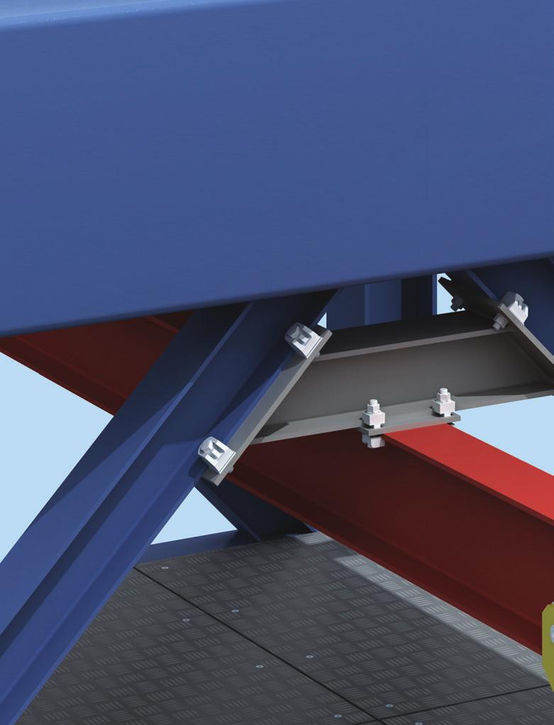
9 Steelwork Fixings 1 Steelwork Fixings Lindapter Steelwork Fixings require no on-site drilling or welding, saving both time and money and are compatible with virtually any size/shape of steel section, in a wide variety of applications. The Girder Clamp symbolises Lindapter s concept perfectly; boldly challenging the need to drill or weld, when a safe, high strength connection can be quickly accomplished by clamping two steel sections together. Although the concept is simple, Lindapter products undergo complex design and testing as the experienced Research & Development team constantly refine, improve and invent to achieve greater product performance and safety approvals. The connections shown throughout this catalogue are actual applications from real project successes, both new construction and the refurbishment of existing structures. Advantages Less design time (Lindapter will design the connection) Independently approved loads and quality standards No on-site drilling or welding Fast and safe construction Hot Working not required Adjustable on-site Less work at height Only hand tools required to install Power not required Ability to deconstruct and multi-cycle Markets include: Plant Engineering Chemical and Petro-chemical Material Handling Structural Engineering Civil Engineering Facades Theatre Equipment Transportation Offshore Applications include: Steel Construction Cranes Lifting Beams Pipe Supports Towers and Masts Almost any steel-to-steel connection 9

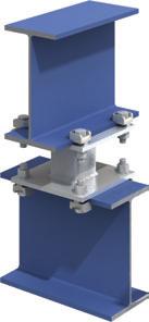
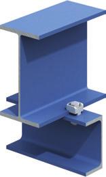
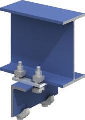
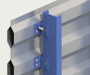
10 Girder Clamps Steelwork Fixings 1 Components of a Girder Clamp 1. Standard Grade 8 Hex Nut 2. Standard Hardened Washer 3. Lindapter Clamp Dependent on the application different clamps could be used i.e. Types A, B, BR, AF, LR, LS, D2 or D3. 4. Packing Piece In combination with the clamps mentioned above these parts increase the tail length to enable the product to sit correctly on the beam. 5. Location Plate (can be supplied if required) This is an essential part of the girder clamp assembly that enables all the components to be located in the correct position. The hole centres and plate thickness are calculated to suit the individual application. 6. Lindapter Clamp This can be of a similar type as 3 (above), although certain products are designed to specifically work together i.e. A + B. 7. Standard Grade 8.8 Hex Bolt or Setscrew Loads The table beneath shows tensile and frictional load capabilities for a standard four bolt Girder Clamp using 4 bolts and 8 clamps at a 90 crossover angle. Lindapter is only too pleased to carry out all design work for individual connections free of charge based on the following details: Load per connection Size and type of both beams Angle of crossover Distance between beams Inclination of beams 6 7 Clamps Types A, B, BR, LR Type AF Bolt size M12 M16 M20 M24 M24 M24 Bolt grade Tensile / for 4 bolts kn ) Friction / for 4 bolts kn ) ) Tightening Torque Nm ) Factor of safety 3.2:1 2) Factor of safety 2:1 Loads are based on a factor of safety (typically 5:1). The reduction of published safety factors is not recommended. Approvals The following approvals apply to Girder Clamps using types A and B only, in sizes from M12 to M24. Further information is available upon request. 10

 + Plate thickness 12 + Lower section 10 + T of lower clamp 10 Three dimples: tail length long (l ) = 93.5 Next standard bolt length = 100.")
 before applying the torque is acceptable.")
11 Bolt Length / Tail Length / Installation Steelwork Fixings 1 Bolt length calculation for a standard Lindapter Girder Clamp, example shows Type A and B M20 Tail length The different tail length can be identified by a code of dimples underneath the clamps. To calculate the bolt length all parts the bolt will go through have to be added up. The next longer standard bolt length should be used. 0.5 bolt Ø as bolt protrusion 10 One dimple: tail length short (s) Height of nut 16 + Washer 3 + T of top clamp + Top section Two dimples: tail length medium (m) + Plate thickness 12 + Lower section 10 + T of lower clamp 10 Three dimples: tail length long (l ) = 93.5 Next standard bolt length = Correct installation of types A and B showing type A as an example Parallel flanges 90º <90º >90º Maximum tail length tolerance of -1mm (up to M16) and -1.5mm (M20, M24) before applying the torque is acceptable. Tapered flanges 90º <_5º 5-8º <90º On 6º and 8º slopes types A and B require a special tail length/packing combination which will allow the clamp to tilt back slightly (incorporated into the combination table on page 15). For applications above 8 please see types AF, LR and LS. 11

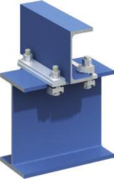
12 Type A Steelwork Fixings 1 Type A Malleable iron, bright zinc plated / hot dip galvanised Nose Recess Clamping Area Skirt Tail T V Y X Typical Applications (see also page 36-39) The recessed top of the type A clamp holds the bolt head captive while the nut is tightened. The skirt prevents the clamp rotating during installation. The clamp is suitable for parallel flanges, and tapered flanges up to 8 and is installed correctly when the clamping area grips the flange. The tail must be chosen to suit the thickness of the flange being gripped. For correct tail length/packing combinations, please see page 15. Safe Working Loads Dimensions Product Bolt 8.8 (5:1 Factor of Safety) Tightening Tail Length V Code Tensile / 1 Bolt Frictional / 2 Bolts Torque Y X short medium long T Width kn kn Nm mm mm mm mm mm mm mm A08 M A10 M A12 M A16 M A20 M A24 M For higher loads the type AF should be used (see page 16). Order example: A16 medium HDG 12

13 Type B Steelwork Fixings 1 Type B Malleable iron, bright zinc plated / hot dip galvanised Nose Flat Top Clamping Area Skirt Tail T V Y X The flat top of the type B clamp allows the bolt head or nut to be rotated. The clamp is suitable for use with bolts, studs, tie rods, J-bolts, parallel flanges, and tapered flanges up to 8. The clamp is installed correctly when the clamping area grips the flange. The tail must be chosen to suit the thickness of the flange being gripped. For correct tail length/packing combinations, please see page 15. Typical Applications (see also page 36-39) Safe Working Loads Dimensions Product Bolt 8.8 (5:1 Factor of Safety) Tightening Tail Length V Code Tensile / 1 Bolt Frictional / 2 Bolts Torque Y X short medium long T Width kn kn Nm mm mm mm mm mm mm mm B08 M B10 M B12 M B16 M B20 M B24 M For higher loads the type AF should be used (see page 16). Order example: B16 medium HDG 13
14 Accessories for Type A and B Steelwork Fixings 1 Type CW - Clipped Washer Mild Steel, bright zinc plated / hot dip galvanised Y X T Product Bolt Dimensions Code Y X T Width mm mm mm mm CW08 M8 4 9, CW10 M CW12 M CW16 M CW20 M A packing used to adjust the tail length of the clamp to meet differing beam flange thicknesses. CW24 M Order example: CW08 BP Type P1 short / P2 short Mild Steel, malleable iron, bright zinc plated / hot dip galvanised A packing used to adjust the tail length of the clamp to meet differing beam flange thicknesses. Y T P1 T P2 X Product Bolt Dimensions Code Y X T P1 T P2 Width P1 P2 mm mm mm mm mm P1S08 P2S08 M P1S10 P2S10 M P1S12 P2S12 M P1S16 P2S16 M P1S20 P2S20 M P1S24 P2S24 M Order example: P1S16 HDG Type T Malleable iron, bright zinc plated / hot dip galvanised A packing, for parallel flanges only, used to fill the nose of type A and B, making it horizontal. The thickness T should be added for tail length and bolt length calculations. The product is for aesthetic purposes only and is not mandatory from a technical perspective. T Product Bolt Dimensions Code T mm T12 M12 3 T16 M16 4 T20 M20 5 T24 M Order example: T12 BP Type W Mild Steel, malleable iron, bright zinc plated / hot dip galvanised T Product Bolt Dimensions Code T mm W08 M8 4 W10 M W12 M W16 M16 8 W20 M A washer used to fill the recess of type A to enable the nut to be tightened. When calculating the bolt length, please add T. Order example: W08 BP 14
15 Plate and Packing Details for Type A and B Steelwork Fixings 1 Location and End Plates L 1 l 1M b 1 L 1 l 1M b 1 L 1 = L 2 = l 1M, l 2M = b 1, b 2 = d = s = Plate length Plate width Hole centres Flange width Hole Ø Plate thickness d b 2 l 2M L 2 l2m d L2 Location Plate Plate Dimensions Material: Mild Steel Grade S275 JR (for other grades please contact Lindapter) End Plate Location Plate End Plate 1) Plate Plate Bolt Hole Ø Thickness Hole Centres Length/Width Thickness Hole Centre Length Hole Centre Width d s l 1M, l 2M min L 1, min L 2 s l 1M min L 1 min l 2M min L 2 mm mm mm mm mm mm mm mm mm M8 9 6 b + 9 b b b l 2M + 40 M b + 11 b b b l 2M + 40 M b + 13 b b b l 2M + 50 M b + 18 b b b l 2M + 60 M b + 22 b b b l 2M + 70 M b + 26 b b b l 2M ) Dependant on the use of the end plate the thickness might need to be increased. Calculation of bolt length see page 11 Tail Length / Packing Combinations for Types A & B For beams up to and including 5 slope Flange Types A & B Thickness M12 M16 M20 M24 mm A,B CW P1S P2S A,B CW P1S P2S A,B CW P1S P2S A,B CW P1S P2S 5 s s m s s m s s m s m s m s l l m s m l s m l s s m s s l s s l m s l s s l l m s l m l s s m l m s s 1-1 l s l s 1-1 l m l m 1-1 l s s l l m s s l l m m m m m s l s s s l s s l s 2-1 m l m l 1-1 m s Tail Length / Packing Combinations for Types A & B For IPN-Beams of an 8 slope Types A & B IPN M12 M16 M20 M24 Profile A,B CW P1S P2S A,B CW P1S P2S A,B CW P1S P2S A,B CW P1S P2S s s m s m s s s m m s m m s l s s m s m l m s l l s s l m m s l m l l s m m l l s = short m = medium l = long P1S = P1 short P2S = P2 short = Type not applicable = Please contact Lindapter For thicker flanges please contact Lindapter. 15
 Recess Nose Skirt Tail With washer Type AFW: Converts recessed clamp to flat top clamp. Flat Top T V Y X With Type AFW washer inverted: Holds the bolt head captive (bolt grade 10.")
16 Type AF Steelwork Fixings 1 Type AF SG iron, hot dip galvanised Without Type AFW washer: Holds the bolt head captive (bolt grade 8.8) Recess Nose Skirt Tail With washer Type AFW: Converts recessed clamp to flat top clamp. Flat Top T V Y X With Type AFW washer inverted: Holds the bolt head captive (bolt grade 10.9 with larger hexagon size M12 - M20) Typical Applications (see also page 36-39) A high friction clamp with a recessed top to hold the bolt head captive while the nut is tightened. Washer type AFW available (see illustration above and page 18). The skirt prevents the clamp rotating during installation. The tail of the AF spans across slotted holes. Suitable for flanges up to 10, ideal for S-beams. The clamp can be combined with type CF. For correct tail length/packing combinations, please see page 19.The type AF is compatible with Grade 8.8 and 10.9 bolts, please refer to the table below for performance comparisons. Safe Working Loads (5:1) Factor of Safety (2:1) Dimensions Product Bolt Tensile / 1 Bolt Frictional 1) / 2 Bolts Tightening Tail Length V T Code Grade Painted Steelwork 2) Galv. Steelwork Torque Y X short medium Type AF Type AF with AFW Width kn kn kn Nm mm mm mm mm mm mm mm AF12 M AF16 M AF20 M AF24 M AF12 M ) AF16 M ) AF20 M ) AF24 M ) ) ) Frictional Load figures are based on Type AF and Location plates in hot dip galvanised finish. Calculated against slip (movement exceeding 0.1mm). 2) Shot blast and painted steelwork 3) 3.2:1 factor of safety 4) For HR or HV bolts (hot dip galvanised and lubricated) please refer to manufacturers recommendation for torque figures. Order example: AF12 short 16
 A high friction clamp which hooks over the flanges of beams, angles and")
17 Type CF Steelwork Fixings 1 Type CF SG iron, hot dip galvanised European Patent No: EP Registered in European Community under design numbers: , , , Nose Anti-rotation markings Legs Y X Y X min T max T V min t max t Typical Applications (see also page 36-39) A high friction clamp which hooks over the flanges of beams, angles and channels. Lindapter markings act as a unique anti-rotation device. The clamp can be combined with all Lindapter Girder Clamp products, including the type AF. Safe Working Loads (5:1) factor of safety (2:1) Product Bolt 8.8 Tensile / 1 Bolt Frictional 1) / 2 Bolts Tightening Dimensions Code Painted Steelwork 2) Galv. Steelwork Torque Y X t T V Width kn kn kn Nm mm mm mm mm mm mm CF12 M CF16 M CF20 M CF Combinations with other Lindapter Clamps kn kn kn Nm CF / A 3) M CF / A 3) M CF / A 3) M CF / AF M CF / AF M CF / AF M Order example: CF12 1) Frictional load figures are based on type CF and location plate in HDG finish. Calculated against slip (movement exceeding 0.1mm). 2) Shot blast and painted steelwork 3) Also applies to type B, BR, LR, D2 or D3 17

18 Accessories for Type AF Steelwork Fixings 1 Type AFCW Mild Steel, hot dip galvanised Product Bolt Dimensions Code Y X T Width mm mm mm mm AF12CW M T AF16CW M Y X AF20CW M A packing used to adjust the tail length of the clamp to meet differing beam flange thicknesses; it has a slight bend along its centre line which flattens out during installation. Order example: AF12CW Type AFP1 / AFP2 Mild Steel, hot dip galvanised Product Bolt Dimensions Code Y X T P1 T P2 Width Y X T P1 P2 mm mm mm mm mm AF12P1 AF12P2 M AF16P1 AF16P2 M AF20P1 AF20P2 M AF24P1 AF24P2 M A packing used to adjust the tail length of the clamp to meet differing beam flange thicknesses. Order example: AF12P1 Type AFW SG iron, malleable iron, mild steel, hot dip galvanised T Product Bolt Dimensions Code T mm AFW12 M12 5 AFW16 M16 5 AFW20 M20 6 AFW24 M24 10 A washer used to fill the recess of the type AF. The washer features two projections which, when the AFW is inverted, will captivate the larger hexagons of 10.9 bolts (M12 M20 only). The M24 version has no projections. T Order example: AFW12 M24 version has no projections. 18
19 Plate and Packing Details for Type AF and CF Steelwork Fixings 1 Location and End Plates L 1 l 1M b 1 L 1 l 1M b 1 L 1 = L 2 = l 1M, l 2M = b 1, b 2 = d = s = Plate length Plate width Hole centres Flange width Hole Ø Plate thickness d b 2 l 2M L 2 l2m L 2 d Location Plate End Plate Plate Dimensions Material: Mild Steel Grade S355 JR (for other grades please contact Lindapter) Plate Calculation of bolt length see page 11 Tail Length / Packing Combinations for Type AF Parallel flanges and beams of up to 10º slope Location Plate End Plate 1) Bolt Hole Ø Thickness Hole Centres Length/Width Thickness Hole Centre Length Hole Centre Width d s l 1M, l 2M min L 1, min L 2 s l 1M min L 1 min l 2M min L 2 mm mm mm mm mm mm mm mm mm M b + 13 b b b l 2M + 80 M b + 18 b b b l 2M M b + 22 b b b l 2M M b + 26 b b b l 2M ) Dependant on the use of the end plate the thickness might need to be increased. The type CF can be used in combination with the type AF (see plate dimensions above), types A, B, and BR (see page 15 for plate dimensions) and types D2, D3 and LR (see page 23 for plate dimensions). Plate Flange Type AF Thickness M12 M16 M20 M24 mm AF AFCW AFP1 AFP2 AF AFCW AFP1 AFP2 AF AFCW AFP1 AFP2 AF AFP1 AFP2 5 s s s s s s s s s s s s s s s s s s s m s s s m s s s s m s s m m s s m m m s m s m s 1-19 m m m s 1-20 s m m s 1-21 m m m s 1-22 m m m s 1-23 m m m s m 1-1 m m s s m m s m 2-1 m s s m 2-1 m 1-1 s m - - Flange Type AF Thickness M12 M16 M20 M24 mm AF AFCW AFP1 AFP2 AF AFCW AFP1 AFP2 AF AFCW AFP1 AFP2 AF AFP1 AFP2 28 m s m m m m m m s m m 1-1 m s m m 1-1 m m m m m 1-33 m m m m 1-34 m 1-2 m m m 1-35 s m s m 1-36 s m m m 1-37 m m 1-2 m m 1-38 m s m m m m m m s m m 1-2 m s m m 1-2 m m m m m m s m m m 1-3 m m m s m m m s m m m m m 1-3 m m m s m m s m m m s m m 1-3 m - 2 s = short m = medium = Type not applicable 19
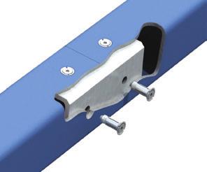
 max V A self adjusting clamp for various flange thicknesses and slopes up to 15. The leg of the saddle prevents the clamp rotating during installation. The LR tail spans slotted holes.")
 Tightening Clamping Range Dimensions Code Tensile / 1 Bolt Frictional / 2 Bolts Torque V Y X T Width with Saddle kn kn Nm mm mm mm mm mm LR10 M10 1.")
20 Type LR Steelwork Fixings 1 Type LR Malleable iron, bright zinc plated / hot dip galvanised Saddle Nose Slot Leg Clip Tail max Y min X max T min V min Y max X min T Typical Applications (see also page 36-39) max V A self adjusting clamp for various flange thicknesses and slopes up to 15. The leg of the saddle prevents the clamp rotating during installation. The LR tail spans slotted holes. For thicker flanges packings P1 long and P2 long are available. For correct tail length/packing combinations please see page 23. Safe Working Loads Product Bolt 8.8 (5:1 Factor of Safety) Tightening Clamping Range Dimensions Code Tensile / 1 Bolt Frictional / 2 Bolts Torque V Y X T Width with Saddle kn kn Nm mm mm mm mm mm LR10 M LR12 M LR16 M LR20 M LR24 M Order example: LR10 BP 20


21 Type D2 / Type D3 Steelwork Fixings 1 Type D2 Malleable iron, bright zinc plated, hot dip galvanised S Nose Recess T Clamping Area Setscrew Tail Y X V Skirt Type D3 Malleable iron, bright zinc plated, hot dip galvanised Flat Top S T V Y X Adjustable clamps that incorporate a setscrew to accommodate a wide range of flange thicknesses. Type D2 has a recessed head to hold the bolt head captive. The skirt prevents the clamp rotating during installation. For flanges up to 5. For thicker flanges packings P1 long and P2 long are available. For correct tail length/packing combinations please see page 23. Typical Applications (see also page 36-39) Correct Installation: Setscrew S needs to be adjusted so that V is 1mm shorter than the flange thickness prior to installation. Adjust the setscrew after installation so that the bolt is 90 to the clamp and the clamp contacts the flange with the clamping area only. Safe Working Loads Product Bolt 8.8 (5:1 Factor of Safety) Tightening Clamping Range Dimensions Code Tensile / 1 Bolt Frictional / 2 Bolts Torque V 1) V 2) Y X S T Width kn kn Nm mm mm mm mm mm mm mm D210 M M D212 M M D216 M M D220 M M D224 M M D312 M M D316 M M ) Setscrew S inserted from above. 2) Setscrew S inserted from below. Order example: D210 BP 21

22 Accessories for Type LR, D2 and D3 Steelwork Fixings 1 Type P1 long / P2 long Mild Steel, malleable iron, bright zinc plated / hot dip galvanised Product Bolt Dimensions Code Y X T P1 T P2 Width P1 P2 mm mm mm mm mm P1L10 P2L10 M Y X T P1 T P2 P1L12 P2L12 M P1L16 P2L16 M P1L20 P2L20 M P1L24 P2L24 M A packing used to adjust the tail length of the clamp to meet differing beam flange thicknesses. Order example: P1L10 BP Type T Malleable iron, bright zinc plated / hot dip galvanised T Product Bolt Dimensions Code T mm T12 M12 3 T16 M16 4 T20 M20 5 A packing to fill the nose of type D2 and D3 making it horizontal. For parallel flanges only. The thickness T should be added for tail length and bolt length calculations. The product is for aesthetic purposes only and is not mandatory from a technical perspective. T24 M Order example: T12 BP Type W Mild Steel, malleable iron, bright zinc plated / hot dip galvanised Product Bolt Dimensions Code T mm T W08 M8 4 W10 M W12 M W16 M16 8 W20 M A washer used to fill the recess of type D2 to enable the nut to be tightened. When calculating the bolt length, please add T. Order example: W08 BP 22
23 Plate and Packing Details for Type LR, D2 and D3 Steelwork Fixings 1 Location and End Plates L 1 l 1M b 1 L 1 l 1M b 1 L 1 = L 2 = l 1M, l 2M = b 1, b 2 = d = s = Plate length Plate width Hole centres Flange width Hole Ø Plate thickness d b 2 l 2M L 2 l2m d L2 Plate Dimensions Material: Mild Steel Grade S275 JR Location Plate End Plate Location Plate End Plate 1) Plate Plate Bolt Hole Ø Thickness Hole Centres Length/Width Thickness Hole Centre Length Hole Centre Width d s l 1M, l 2M min L 1, min L 2 s l 1M min L 1 min l 2M min L 2 mm mm mm mm mm mm mm mm mm M b + 11 b b b l 2M + 50 M b + 13 b b b l 2M + 60 M b + 18 b b b l 2M + 70 M b + 22 b b b l 2M + 90 M b + 26 b b b l 2M ) Dependant on the use of the end plate the thickness might need to be increased. Calculation of bolt length see page 11 Tail Length / Packing Combinations for Type LR Parallel flanges Type M 10 M 12 M 16 M 20 M 24 Combinations Clamping Range LR P1L P2L mm mm mm mm mm Tail Length / Packing Combinations for Type D2 & D3 Parallel flanges and beams of up to 5 slope Type M 10 M 12 M 16 M 20 M 24 D2 D2 / D3 D2 / D3 D2 D2 Combinations Clamping Range D P1L P2L mm mm mm mm mm 1 1) ) Setscrew S inverted. Tail Length / Packing Combinations for Type LR For IPN-Beams of an 8 slope IPN M10 M12 M16 M20 M24 Profile LR P1L P2L LR P1L P2L LR P1L P2L LR P1L P2L LR P1L P2L P1L = P1 long P2L = P2 long = Type not applicable For thicker flanges please contact Lindapter. 23

24 Type LS Steelwork Fixings 1 Type LS Cast Stainless Steel Grade 316 Registered in European Community under design Numbers: , , , US Design Patent No: US D597,393 S. Multiple International Design Patents Pending Nose Tail min Y max X max T min V max Y min X min T Typical Applications (see also page 36-39) max V A self adjusting clamp for various flange thicknesses and slopes of up to 10. The special serrations on the tail prevent the clamp rotating during installation. The LS tail spans over slotted holes. For thicker flanges LSP2 packings are available. For correct tail length / packing combinations, please see page 25. Safe Working Load Clamping Product Bolt A4-70 (5:1) Factor of Safety (2:1) Tightening Range Dimensions Code Tensile / 1 Bolt Frictional 1) / 2 Bolts Torque V Y X T Width kn kn Nm mm mm mm mm mm LS10 M LS12 M LS16 M LS20 M ) Frictional loads calculated against slip (movement exceeding 0.1mm). Order example: LS10 24
25 Accessories, Plate and Packing Details for Type LS Steelwork Fixings 1 Type LSP2 Stainless Steel Grade 316 Y X T Product Bolt A4-70 Dimensions Code Y X T Width LS10P2 M LS12P2 M LS16P2 M LS20P2 M Packing used to adjust the tail length of the clamp to meet differing beam flange thicknesses. Order example: LS10P2 Accessories Packings are available upon request. Location and End Plates L 1 l 1M b 1 L 1 l 1M b 1 L 1 = L 2 = l 1M, l 2M = b 1, b 2 = d = s = Plate length Plate width Hole centres Flange width Hole Ø Plate thickness d b 2 l 2M L 2 l2m d L2 Location Plate End Plate Plate Dimensions Material: Stainless Steel Grade 304 or 316 Plate Location Plate End Plate 1) Bolt Hole Ø Thickness Hole Centres Length/Width Thickness Hole Centre Length Hole Centre Width d s l 1M, l 2M min L 1, min L 2 s l 1M min L 1 min l 2M min L 2 mm mm mm mm mm mm mm mm mm mm M b + 11 b b + 11 b l 2M + 60 M b + 13 b b + 13 b l 2M + 60 M b + 18 b b + 18 b l 2M + 80 M b + 22 b b + 22 b l 2M ) Depending on type of connection and associated end plate use, the thickness may need to be modified to comply with accepted local design codes. Calculation of bolt length see page 11 Tail Length / Packing Combinations for Type LS For beams up to and including 5 slope Plate Flange Type LS Thickness M10 M12 M16 M20 mm P2 P2 P2 P Flange Type LS Thickness M10 M12 M16 M20 mm P2 P2 P2 P For thicker flanges, please contact Lindapter. P2 = LSP2 25


26 Type BR / Type RC Steelwork Fixings 1 Type BR Malleable iron, bright zinc plated / hot dip galvanised Nose Flat Top Clamping Area Skirt Tail T V Y X Safe Working Loads A versatile clamp for steel beams or rails. The skirt prevents the clamp from rotating during installation. The BR tail spans slotted holes. Suitable for flanges up to 8. Dimensions Product Bolt 8.8 (5:1 Factor of Safety) Tightening Tail Length V Code Tensile / 1 Bolt Frictional / 2 Bolts Torque Y X short medium T Width kn kn Nm mm mm mm mm mm mm BR BR BR BR Order example: BR12 short HDG Type RC Forged steel, corrosion protection as required Nose Hole to suit M12-M24 Skirt Tail A special clamp for securing rails or steel beams of 10mm or greater. Packings are available for thicker flanges. The RC tail spans slotted holes. Suitable for flanges of up to 5. The product will be drilled to suit the hole size and position requirements of the application. X L W H V Min. Safe Working Load 1) Product Bolt 8.8 (5:1 Factor of Safety) Tightening Dimensions Code Tensile / 1 Bolt Torque Tail Length V X L H Width W kn Nm mm mm mm mm mm RCS12 M RCS16 M RCS20 M RCS24 M ) The safe working load depends on the position of the bolt hole. The greater dimension X the lower the load. Order example: RCS12 HDG with dimension X = mm 26
27 Accessories and Packing Details for Type BR Steelwork Fixings 1 Type CW - Clipped Washer Mild Steel, bright zinc plated / hot dip galvanised Packing used to adjust the tail length of the clamp to meet differing beam flange thicknesses. Y X T Product Bolt Dimensions Code Y X T Width mm mm mm mm CW12 M CW16 M CW20 M CW24 M Order example: CW12 BP Type P1 short / P2 short Mild Steel, malleable iron, bright zinc plated / hot dip galvanised Packing used to adjust the tail length of the clamp to meet differing beam flange thicknesses. Y T P1 T P2 X Product Bolt Dimensions Code Y X T P1 T P2 Width P1 P2 mm mm mm mm mm P1S12 P2S12 M P1S16 P2S16 M P1S20 P2S20 M P1S24 P2S24 M Order example: P1S12 BP For Type BR please see the following: Location and End Plates, page 15 Calculation of bolt length, page 11 Tail Length / Packing Combinations for Type BR For rails up to and including 8 slope NB: The flange thickness refers to t 1. t 1 Flange Type BR Thickness M12 M16 M20 M24 mm BR CW P1S P2S BR CW P1S P2S BR CW P1S P2S BR CW P1S P2S 5 s m s s s s m m s s s s s s s m s m m s s m s s m s s s s m s m s s s s s s m s m m s s s m s m s s 1-1 m s s m 1-1 s m m m 1-1 s m s s s m s m 2-1 m m s m m m m s s 1-1 s s m s 1-1 s s s m 1-1 s s s s 2-1 m m s s 2-1 m s m m 2-1 m s s 1-2 m 2-1 s 1-1 s For thicker flanges, please contact Lindapter. Type BR is only available with tail length short and medium. s = short m = medium P1S = P1 short P2S = P2 short = Type not applicable 27
.")
28 Type HD Steelwork Fixings 1 Type HD Malleable iron, SG iron, corrosion protection as requested Type HD Hard / Soft Clip Plug Leg Nose Skirt Type HD Spring Clip Elastomer Spring The type HD rail clamps facilitate the precise alignment of rails by allowing a high degree of stepless lateral adjustability. Three variants are available (see opposite page). Technical Data Suitable for all rails with tapered flanges and crane speeds of up to 60m/min. For wheel loads above 400kN or lateral loads higher than wheel loads please contact Lindapter. Normal High Dimensions Product Clip Bolt 8.8 Lateral Conditions Lateral Conditions Leg Stud Lateral Adjustm. Plate Width Distances Width Code Type SWL* Tightening SWL* Tightening V Length H max L min A X 2) Y 2) W Torque Torque kn Nm kn Nm mm mm mm mm mm mm mm HD20 H Hard M F - 8 F + 38 ± 11.5 B HD20 S Soft M F - 5 F + 40 ± 11.5 B HD20 SP Spring M F - 7 F + 40 ± 11.5 B HD20 S-P Soft & Pad M F 1) F + 45 ± 11.5 B HD20 SP-P Spring & Pad M F - 2 1) F + 45 ± 11.5 B HD24 H Hard M F - 8 F + 41 ± 8 B HD24 S Soft M F - 4 F + 43 ± 8 B HD24 SP Spring M F - 7 F + 43 ± 8 B HD24 S-P Soft & Pad M F + 1 1) F + 48 ± 8 B HD24 SP-P Spring & Pad M F - 2 1) F + 48 ± 8 B *4:1 Factory of Safety 1)Based on 5mm thick resilient pad. 2)Based on plug set at 3 o clock position. NB: Leg length V for use with rail sections only with tapered base. For parallel sections please refer to Lindapter. Order example: HD20 H HDG for rail: 28

29 Type HD Steelwork Fixings 1 Type HD Hard Clip Leg length V should be selected to clamp rail down tightly and allow no vertical rail movement. Not to be used when the rail is supported by a resilient pad. H F V Y X B A Type HD Soft Clip Leg length V should be selected to allow vertical rail movement caused by rail wave, whilst holding the rail in precise alignment laterally. Rail ends need to be fixed. H F V Y X B A Type HD Spring Clip The spring clip version incorporates an elastomer spring into the nose of the product, designed to provide some vertical restraint to the rail whilst still allowing the rail to lift with rail wave. The elastomer spring is manufactured from high density synthetic polymer which has a Shore A hardness of The spring is unaffected by salt water and most chemicals and has a high resistance to abrasion. H Y X F B A V Resilient Pad Both the spring and soft clips can be used with a resilient pad to decrease track running noise / structural vibration, level out irregular contact between surface and rail and to spread wheel load evenly over a wider area. V Resilient Pad Installation 1. Position clip on bolt or stud. Place the plug in 3 o clock position and tighten the nut. 2. Rotate the built in nut profile in a clockwise direction from the 3 o clock position to locate the clip against the rail and laterally adjust the rail if required. 3. Apply the recommended torque to the hexagon nut. W +L -L 29


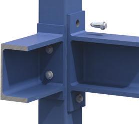
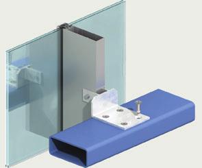
30 Type BSNT / Type BSLN Steelwork Fixings 1 Type BSNT Malleable iron, bright zinc plated / hot dip galvanised Nose Flat Top T Y X A special clamp for the installation of beams flange to flange. The location plate is substituted by a connecting frame made of steel flats equalling the flange thicknesses in height. The clamps are welded to this frame. Safe Working Loads Product Bolt 8.8 (5:1 Factor of Safety) Tightening Dimensions Code Tensile / 1 Bolt Torque Y X T Width kn Nm mm mm mm mm BSNT12 M BSNT16 M BSNT20 M BSNT24 M Order example: BSNT12 HDG Type BSLN Malleable iron, bright zinc plated / hot dip galvanised Extended Nose Flat Top Skirt Tail T K Y X V Safe Working Load A special clamp designed with a longer nose to extend the contact area with the steel section. For parallel flanges only. Can be used with types CW, P1 short, P2 short. Dimensions Product Bolt 8.8 (5:1 Factor of Safety) Tightening Tail Length Code Tensile / 1 Bolt Torque Y X V T Width kn Nm mm mm mm mm mm BSLN12 M BSLN16 M Order example: BSLN12 HDG 30

 Tightening Clamping Range Dimensions Bolt Bolt Tensile / 1 Bolt Torque W X V T Width kn Nm mm mm mm mm mm F910NC F910NB M10 2 20 19-42 25 13 19 24 F912NC F912NB M12 2.")
31 Type F9 / Type HW/HC Steelwork Fixings 1 Type F9 Malleable iron, bright zinc plated / hot dip galvanised Nut Bolt Single Leg V Jaws W X T V Double Leg A flange clamp for connecting parallel running steel sections with flanges of the same width. The clamps can be used with bolts or alternatively with threaded rod. Not suitable for tapered flanges. Product Code Safe Working Loads with without Bolt 4.6 (5:1 Factor of Safety) Tightening Clamping Range Dimensions Bolt Bolt Tensile / 1 Bolt Torque W X V T Width kn Nm mm mm mm mm mm F910NC F910NB M F912NC F912NB M F916NC F916NB M F920NC F920NB M F924NC F924NB M Order example: F910NC HDG Type HW/HC Malleable iron, bright zinc plated / hot dip galvanised X Hemispherical Washer W2 R W1 L Y 10 Hemispherical Cup For vertical suspension on angled surface of up to 10 swing either side of the vertical. The hemispherical washer (HW) can be used without the cup. Loads are subject to applications, please contact Lindapter. Dimensions Product Code Hemispherical Washer Hemispherical Cup Hemispherical Washer & Cup Hemispherical Washer Hemispherical Cup X W 1 Y W 2 R L mm mm mm mm mm mm HW HW HW10 HC HW12 HC HW16 HC HW20 HC HW24 HC Order example: HC10 BP 31

 SWL Directions: 360º rotation Angle: 0-90º Type LP6 Type LP6 Lifting Point with 6 Bolts Loading: Various sizes available up to 10t (98kN) SWL Directions: 360º rotation")
32 Type SC / Type LP Steelwork Fixings 1 Type SC / Type LP Corrosion Protection as required Custom built connections for specific application requirements, such as vertical loads, loads at an angle and rotation of up to 360. Typical applications are shown. Other loads and designs are available. All loads subject to suitability of supporting section. Type SC Type SC Shackle Clamp with 4 Bolts Loading: Various sizes available up to 6t (60kN) SWL Directions: vertical lift Angle: ± 10º Type LP4 Type LP4 Lifting Point with 4 Bolts Loading: Various sizes available up to 7t (68kN) SWL Directions: 360º rotation Angle: 0-90º Type LP6 Type LP6 Lifting Point with 6 Bolts Loading: Various sizes available up to 10t (98kN) SWL Directions: 360º rotation Angle: 0-90º Order details: Loading, rotation, angle and beam dimensions 32

33 Type FC Steelwork Fixings 1 Type FC Forged steel, bright zinc plated plus JS500 The Flush Clamp is a highly adjustable Girder Clamp System without the need of a location plate. Suitable for connecting beams of varying widths and thicknesses. Suitable for flanges of up to 10 slope. For convenience and ease of installation, the Flush Clamp features an innovative beam width selector allowing the installer to quickly adjust the clamp to the required setting (marked from 3 to 7 ). Teeth on the special bolt and special washer engage teeth on the body of the clamp, preventing movement. Special Safe Working Loads Product Bolt (5:1 Factor of Safety) Tightening Clamping Range V Dimensions Code 8.8 Tensile / 4 Bolts Frictional / 4 Bolts Torque Flange Thickness Flange Width 1) T B kn kn Nm mm mm mm mm FC16 M ) Depending on beam connection angles (see table below). Order example: FC16 Flat washer Special washer Half nut Nut Body max T min V min T max V Special Bolt B Minimum Possible Beam Connection Angles Bottom Beam Top Beam Flange Width mm mm mm mm mm 76.2 mm mm mm mm mm Angle 33


34 Loads and Specifications Steelwork Fixings 1 Loads and Specifications Lindapter steel connections are designed to suit the loading condition of each application, as defined below. Safe working loads published in this catalogue are for bolt grade 8.8 unless otherwise stated. Should you require assistance in selecting the correct product for your needs, please contact Lindapter. Tensile Loading In tensile applications the load transmits a force parallel to the centre line of the bolt shank, hence applying a load to the contact point of the Lindapter. See product data tables for allowable tensile loads at varying bolt sizes. Combined Loads When the fixings are subject to more than one load condition, the resulting forces must be calculated to determine the product and bolt sizes required. Please contact Lindapter with your application. Frictional Loading The force is applied at 90 to the bolt shank. The point at which slip occurs depends upon the condition and finish of the steelwork, the coating of the Lindapter and the grade of bolt used. Slip is defined as the constant load at which relative movement between clamped components exceeds 0.1mm. Compression Loading Force here is applied direct to the supporting section rather than the Lindapter products. If, however, there is a gap between the surfaces being connected, the buckling strength of the supporting fabrication must be considered. Shear Loading The Safe Working Load of the assembly is determined by the bolt grade and diameter as the force is resisted by the cross sectional area of the bolt shanks. It is recommended that reference be made to the bolt manufacturers technical literature or the relevant structural steel design code to ascertain a Safe Working Load per bolt. Torque The recommended torque values stated in the product sections must be applied in order to achieve the stated Safe Working Loads. Any reduction in torques applied will lower the product Safe Working Load and is not recommended. 34
35 Technical Enquiry Steelwork Fixings 1 Technical Enquiry Date Company Full Name Position Department Address Town Post Code Tel Fax Web Your details may be shared with your nearest distributor to ensure your enquiry is dealt with as quickly as possible Project Name / Reference: Is your case comparable with an application in this catalogue? If yes, please state page and illustration number (if applicable) If no, please enclose drawing detail Load per connection: Tensile kn Frictional kn Please state any special load conditions (vibration, etc.) Static Load Dynamic Load Load Cycles Beam Type Flange Width Flange Thickness Top Beam Bottom Beam 4. Corrosion protection of beams Number of connections required enquiries@lindapter.com 35


36 Typical Applications Steelwork Fixings 1 A selection of connection examples are shown below, please visit the Lindapter website to view more applications. GC001-1 GC001-3 GC001-4 GC001-5 GC001-6 GC001-7 GC001-9 GC GC


37 Typical Applications Steelwork Fixings 1 GC002-1 GC002-2 GC002-3 GC002-4 GC003-1 GC003-3 GC003-4 GC004-1 GC


38 Typical Applications Steelwork Fixings 1 GC004-4 GC005-1 GC005-2 GC006-1 GC006-2 GC006-3 GC006-5 GC006-6 GC


39 Typical Applications Steelwork Fixings 1 GC008-2 GC008-3 GC008-4 GC009-1 GC009-2 GC010-1 GC011-1 GC011-2 GC


40 Cavity Fixings 2 Cavity Fixings The Hollo-Bolt and Lindibolt eliminate the need for conventional through-bolting or welding of structural hollow section (SHS) or any steel structure where access is only available from one side. In the late 1940s, Lindapter revolutionised blind connections with the development of the original Lindibolt, for situations where access to both sides of the steel was restricted. Following the introduction and wide acceptance of SHS, the Hollo-Bolt was invented to suit virtually any type of hollow section, including square, rectangular, circular and oval profiles. As with all Lindapter products, the R&D department has continued to develop the range with the rapid expansion in diameters, lengths, finishes, and head types. Following comprehensive testing, The Steel Construction Institute (SCI) and British Constructional Steelwork Association (BCSA) recognise the Hollo-Bolt as a primary structural connection, in the design guide Joints in Steel Construction Simple Connections. The Hollo-Bolt has CE Mark Certification, and is also approved by the Deutsches Institut für Bautechnik and TÜV NORD. Both the Lindibolt and Hollo-Bolt enable fast and safe construction and can be swiftly installed by simply inserting the product into pre-drilled holes, then tightening to the recommended torque using hand tools. Typical Hollo-Bolt applications include: Primary Connections Secondary Connections Bridges Cladding Balconies Towers and masts Staircases and handrails Glazing and roofs 40


41 Type HB - Hollo-Bolt Cavity Fixings 2 Type HB - Hollo-Bolt Steel, bright zinc plated plus JS 500 Steel, hot dip galvanised Stainless Steel Grade 316 Collar Rubber Washer Sleeve Cone Bolt Suitable for hollow sections, tubes and where access is available from one side only. For high corrosion protection the Hollo-Bolt comes with additional JS500 protection as standard or hot dip galvanised. Sizes M16 and M20 have a patented collapse mechanism for optimised clamping force. Awarded the Design Council s Millennium Product status for innovation in the year Hollo-Bolt : M8, M10, M12 Hollo-Bolt : M16, M20 Installation Hollo-Bolt D H L d D H L Rubber Washer d 1. Align pre-drilled fixture and steelwork. Insert Hollo-Bolt through fixture and steelwork. W W Rubber Washer compressed / increased clamping force 2. Grip the Hollo-Bolt collar with an open ended spanner. Across Flats A/F 8 3. Using a torque wrench, tighten the central bolt to the recommended torque. 41

42 Type HB - Hollo-Bolt Cavity Fixings 2 Type HB - Hollo-Bolt Product Bolt Clamping Outer Sleeve Collar Tightening- Safe Working Loads 2) Code Thickness Ply 1) Height Ø Torque (5:1 Factor of Safety) W min t Length Outer Ø H D A/F Tensile Single Shear mm mm L d d mm mm Nm kn kn HB08-1 M8x HB08-2 M8x HB08-3 M8x HB10-1 M10x HB10-2 M10x HB10-3 M10x HB12-1 M12x HB12-2 M12x HB12-3 M12x HB16-1 M16x HB16-2 M16x HB16-3 M16x HB20-1 M20x HB20-2 M20x HB20-3 M20x Order example: HB08-1 BP plus JS 500 1) Type HB (HB16 and HB20 only) require the thickness of the outer ply (min t) to be at least 8mm. If necessary, spacer washers should be used beneath the collar to increase the thickness to 8mm. 2) The Hollo-Bolt can be used on a wide variety of steel hollow shape sections; safe working loads shown are based on use in S275 structural hollow section. The safe working loads, in both tension and shear, are applicable to the Hollo-Bolt only. Failure of the section, particularly on those with thin walls and a wide chord face, could occur at a lower figure and its strength should be checked by a qualified structural engineer. Joints in Steel Construction - Simple Connections The tables above and on the opposite page state the safe working loads with a 5:1 factor of safety and should be used for secondary applications. For primary design, please consult the guide Joints in Steel Construction - Simple Connections. The guide provides design guidance for the use of Hollo-Bolt and gives essential information for structural steelwork connections for use in buildings designed by the Simple Method i.e. braced frames where connections carry mainly shear and axial loads only. To obtain further details on the Simple Connections guide please contact: The Steel Construction Institute Tel: +44 (0) Fax: +44 (0) Published by SCI/BCSA Connections Group. Publication Number: P212 ISBN Lindapter is a member of SCI and BCSA For Eurocode design please refer to page 44. Bolt Diameter, Hole and Edge distances for all variants of Type HB excluding Flush Fit For Flush Fit figures see page 43. Clearance Type Hole Ø Hole Distances Edge Distances d 1 min A min B B+C mm mm mm mm HB08 14 (+1.0 / -0.2) B + C > 17.5 HB10 18 (+1.0 / -0.2) B + C > 22.5 HB12 20 (+1.0 / -0.2) B + C > 25.0 HB16 26 (+2.0 / -0.2) B + C > 32.5 HB20 33 (+2.0 / -0.2) B + C > 33.0 min t d 1 d 1 A B C 42

 allowing the Flush Fit to be installed without the requirement of specialist skills or equipment.")
43 Type HBFF - Hollo-Bolt Flush Fit Cavity Fixings 2 Type HBFF - Hollo-Bolt Flush Fit Steel, bright zinc plated plus JS 500 Steel, sheraplex Stainless Steel Grade 316 Registered in the European Community under the Design Numbers: , , , D L d Sleeve H W Cone Installation Nut A/F The latest Hollo-Bolt creates immense opportunity for architectural design as the bolt is concealed within the steel with no protruding bolt head or collar. Installation is fast and simple using Lindapter's innovative installation nut (one included per box) allowing the Flush Fit to be installed without the requirement of specialist skills or equipment. min t Product Counter Clamping Outer Sleeve Collar Installation Tightening Safe Working Loads 1) Code Sunk Thickness Ply Overall Tool Torque (5:1 Factor of Safety) Bolt Length Outer Ø Height Ø A/F Tensile Single (inc. collar) Shear W min t L d H D mm mm mm mm mm mm mm mm Nm kn kn HBFF08-1 M8x HBFF08-2 M8x HBFF08-3 M8x HBFF10-1 M10x HBFF10-2 M10x HBFF10-3 M10x HBFF12-1 M12x HBFF12-2 M12x HBFF12-3 M12x Order example: HBFF08-1 BP plus JS 500 without / with installation nut(s) 1) The Hollo-Bolt can be used on a wide variety of steel hollow shape sections; safe working loads shown are based on use in S275 structural hollow section. The safe working loads, in both tension and shear, are applicable to the Hollo-Bolt only. Failure of the section, particularly on those with thin walls and a wide chord face, could occur at a lower figure and its strength should be checked by a qualified structural engineer. Bolt Diameter, Hole and Edge Distances Type HBFF Clearance Countersunk Type Hole Ø Ø Depth Hole Distances Edge Distances d 1 d 2 t 1 min A min B B+C mm mm mm mm mm mm HBFF08 14 (+1.0 / -0.2) B + C > 17.5 HBFF10 18 (+1.0 / -0.2) B + C > 22.5 HBFF12 20 (+1.0 / -0.2) B + C > 25.0 t 1 90º d 2 d 1 A d 1 B C Installation Hollo-Bolt Flush Fit Installation nut 1. Align pre-drilled fixture and steelwork. Insert Hollo-Bolt through fixture and steelwork. 2. Apply installation nut and grip nut with an open ended spanner. 3. Using a torque wrench, tighten the central counter-sunk bolt to the recommended torque. 43
44 Tensile and Shear Resistance Hollo-Bolt Cavity Fixings 2 Characteristic values of tensile and shear resistance for Hollo-Bolt taken from ETA-10/ Standard Hollo-Bolt Designation Nominal Size Tensile Shear Material Strength F t,rk (kn) F v,rk (kn) of Sleeve N/mm 2 Flush Fit Hollo-Bolt Designation Nominal Size Tensile Shear Material Strength F t,rk (kn) F v,rk (kn) of Sleeve N/mm 2 HB08 M HB10 M HB12 M HB16 M HB20 M HBST08 M HBST10 M HBST12 M HBST16 M HBST20 M HBFF08 M HBFF10 M HBFF12 M HBSTFF08 M HBSTFF10 M HBSTFF12 M Countersunk Hollo-Bolt Designation Nominal Size Tensile Shear Material Strength F t,rk (kn) F v,rk (kn) of Sleeve N/mm 2 Button Head / Security Hollo-Bolt Designation Nominal Size Tensile Shear Material Strength F t,rk (kn) F v,rk (kn) of Sleeve N/mm 2 HBCSK08 M HBCSK10 M HBCSK12 M HBCSK16 M HBSTCSK08 M HBSTCSK10 M HBSTCSK12 M HBSTCSK16 M HBBH/HBFT/HBPR M HBBH/HBFT/HBPR M HBBH/HBFT/HBPR M The characteristic values for the Hollo-Bolt listed in the above tables are for use when designing bolted connections to Eurocode 3 only, these are not standard safe working loads. Hollo-Bolt lengths 1, 2 and 3 are covered by this ETA-10/0416. The characteristic values are used to determine the design resistance of the Hollo-Bolt. The design resistance is calculated by dividing the characteristic value by a partial factor gm2. The partial factor is a nationally determined parameter (gm2 =1.25 in the UK). For standard Hollo-Bolt safe working loads with a factor of safety of 5:1 please refer to the Hollo-Bolt tables on pages 42 an 43. The characteristic values are valid for the Hollo-Bolt assembly itself, in any connection detail the design resistance of the connection may be limited to a lesser value. For example, when the thickness of the connected component is small, pull out failure may occur before failure of the Hollo-Bolt. Design checks should be carried out on the section member to determine the static design resistance. The SCI Greenbook publication P358 Joints in Steel construction, Simple Joints to Eurocode 3 contains a number of checks on the section. The characteristic values are only valid when the Hollo-Bolts are installed as per our installation instructions. Hexagonal Head Flush Fit Countersunk (Head) Button Head Security Availability of Lindapter Head Variations Stainless Shera- Hot Dip Type M8 M10 M12 M16 M20 JS500 Steel plex Galv. Hex Head Flush Fit Countersunk Button Head 44


 The safe working loads, in both tension and shear, shown above are applicable to the Lindibolt 2 only.")
45 Type LB2 - Lindibolt 2 Cavity Fixings 2 Type LB2 - Lindibolt 2 Steel, bright zinc plated Stainless Steel Grade 316 Washer Main Body Setscrew Cone Locknut Nut D C W F d Y P W A self heading bolt suitable for connecting steelwork to hollow-sections, tubes and where access is available from one side only. The Lindibolt 2 uses a standard clearance hole. Safe Working Load 1) Product Lindibolt Hole Ø (Factor of Safety 5:1) Clamping Projection Main Body B and Nut C&D Setscrew F Code Size Length d Tensile Single Length Thread Tightening Bolt Tightening Y min max Shear W P Torque A/F F Torque A/F mm mm mm kn kn mm mm mm Nm mm Nm mm LB10 M M M5 6 8 LB12 M M M LB16 M M M LB20 M M M LB24 M M M ) The safe working loads, in both tension and shear, shown above are applicable to the Lindibolt 2 only. Failure of the section, particularly on those with thin walls and a wide chord face, could occur at a lower figure and its strength should be checked. Order example: LB10 BP Installation 1. Set nut (C) at (W) plus projection (P). Tighten Locknut (D). 2. Align pre-drilled fixtures. Insert Lindibolt through both fixtures, cone end first. 3. Hold nut (C) with spanner and tighten bolt (F). Loosen off locknut (D) and tighten nut (C). Secure by re-tightening locknut (D). 45


46 Typical Applications Cavity Fixings 2 HB001 HB002 HB003 HB004 HB005 HB006 46


47 Typical Applications Cavity Fixings 2 HB007 HB008 HB009 HB010 HB011 HB012 47


48 Composite Decking Fixings 3 Composite Decking Fixings A range of high quality, cost effective building services connections designed to fit inside the dovetail shaped re-entrant channel of decking profiles, compatible with all major manufacturers including CMF, Tata Steel, Kingspan, SMD and Richard Lees. To apply the published static loads it is important that all the Lindapter Composite Decking Fixings are installed only when the slab has been poured and the concrete reaches full strength. Please refer to decking manufacturers data sheets for slab loading. Advantages include: Speed of installation No special tools required No weakening of the decking profiles No damage of the surfaces of the decking No possibility of delamination Adjustable and easily removable 48
. Safe Working Load Product Rod (3:1 Factor of Safety) Tightening Code 4.6 Tensile / 1 Rod Torque kn Nm AW06 M6 1.")

49 Type AW Composite Decking Fixings 3 Type AW - Alphawedge Locking Plate: Pre-galvanised strip Wedge: Malleable iron, bright zinc plated Wedge Locking Plate The Alphawedge is designed for Ribdeck AL, E60 and 80 profiles manufactured by Richard Lees Steel Decking (see page 56). Safe Working Load Product Rod (3:1 Factor of Safety) Tightening Code 4.6 Tensile / 1 Rod Torque kn Nm AW06 M AW08 M AW10 M Order example: AW06 Installation Pre-assemble the Locking Plate and Alphawedge (flat surface facing up) onto the threaded rod. 2. Insert wedge into the re-entrant channel of the decking, rotate Slide plate up the threaded rod, over the wedge, to lock it in position into the channel. 4. Tighten the locknut beneath the plate to hold the assembly in position. Note: If the decking profile is deformed/distorted, the fixing should not be installed. If in doubt, please contact Lindapter s Technical Support Department for advice 49
 (see page 56).")
 Tightening Code 4.6 Tensile / 1")
50 Type MF Composite Decking Fixings 3 Type MF Bracket: Steel strip, zinc plate + JS 500 Met-Nut: Malleable iron, bright zinc plated Met-Nut Bracket The Type MF is designed for MetFloor 60 & Metfloor 80 profiles manufactured by Composite Metal Flooring (CMF ) (see page 56). Please note, although this fixing is similar in appearance to the Lindapter Type MW2, the Type MF should not be used in profiles manufactured by Kingspan Structural Products. Safe Working Load Product Rod (3:1 Factor of Safety) Tightening Code 4.6 Tensile / 1 Rod Torque kn Nm MF06 M MF08 M MF10 M Order example: MF06 Installation Pre-assemble the bracket and Met-Nut (flat surface facing up) onto the threaded rod and insert one side of the bracket into the re-entrant channel of decking. 2. Insert the other side of the bracket into position inside the decking. 3. Using either the threaded rod or thumb and forefinger, turn the Met-Nut clockwise until the position in Fig. 4 has been achieved. 4. Tighten the nut on the rod to a torque of 10Nm (prevent rod from rotating). Note: If the decking profile is deformed/distorted, the fixing should not be installed. If in doubt, please contact Lindapter s Technical Support Department for advice. 50
. Safe Working Load Product Rod (3:1 Factor of Safety) Tightening Code 4.6 Tensile / 1 Rod Torque kn Nm MW06 M6 1.")

51 Type MW2 Composite Decking Fixings 3 Type MW2 - Multiwedge 2 Bracket: Pre-galvanised strip Multinut: Malleable iron, bright zinc plated Multinut Bracket The Multiwedge 2 is designed for Multideck 60 and Multideck 80 profiles manufactured by Kingspan Structural Products (see page 56). Safe Working Load Product Rod (3:1 Factor of Safety) Tightening Code 4.6 Tensile / 1 Rod Torque kn Nm MW06 M MW08 M MW10 M Order example: MW06 Installation Pre-assemble the bracket and Multi-Nut (flat surface facing up) onto the threaded rod and insert one side of bracket into re-entrant channel of decking. 2. Snap other leg of bracket into position inside the decking and slide the assembly to desired position along length of re-entrant channel. 3. Push and turn the multi-nut clockwise until it locks into the channel walls. 4. Tighten the hexagon nut beneath the assembly. Note: If the decking profile is deformed/distorted, the fixing should not be installed. If in doubt, please contact Lindapter s Technical Support Department for advice 51
. Safe Working Load Product Rod (3:1 Factor of Safety) Tightening Code 4.6 Tensile / 1 Rod Torque kn Nm SD206 M6 1.0 12 SD208 M8 1.")

52 Type SD2 Composite Decking Fixings 3 Type SD2 - Slimdek 2 Pre-galvanised strip Inner Body V-Nut Main Body Cam The Slimdek 2 is designed for the ComFlor 225 profile manufactured by Tata Steel. It gives a fully flexible suspension position (see page 56). Safe Working Load Product Rod (3:1 Factor of Safety) Tightening Code 4.6 Tensile / 1 Rod Torque kn Nm SD206 M SD208 M SD210 M Order example: SD206 Installation With Slimdek 2 in its retracted position (as supplied) locate the fixing in the re-entrant channel. 2. Hold Slimdek 2 in position with one hand, then rotate cam into the direction shown above with a spanner. 3. Rotate the nut until the inner body of the fixing locates against the re-entrant channel, and the nut feels tight. 4. Offer the V-Nut on a threaded rod up to the main body. 5. Rotate V-Nut through 90 to allow it to sit at the bottom of the Slimdek 2 body. 6. Secure the assembly with a nut. Note: If the decking profile is deformed/distorted, the fixing should not be installed. If in doubt, please contact Lindapter s Technical Support Department for advice 52
 (see page 56).")


53 Type TR60 Composite Decking Fixings 3 Type TR60 Locking Plate: Pre-galvanised strip Wedge: Malleable iron, bright zinc plated TR60/TR80 Wedge Locking Plate The TR60 fixing is designed for the TR60, TR60+, TR80 and TR80+ profiles manufactured by Structural Metal Decks (SMD ) (see page 56). Safe Working Load Product Rod (3:1 Factor of Safety) Tightening Code 4.6 Tensile / 1 Rod Torque TR6006 M TR6008 M TR6010 M kn Nm TR60+/TR80+ Order example: TR6006 Installation Pre-assemble the locking plate and wedge (flat surface facing up) onto the threaded rod. 2. Insert wedge into the re-entrant channel of the decking and rotate until the chamfered cams engage on the sides of the channel. 3. Slide the plate up the threaded rod and over the wedge to lock it into position in the channel. 4. Tighten the locknut beneath the plate to hold the assembly in position. Note: If the decking profile is deformed/distorted, the fixing should not be installed. If in doubt, please contact Lindapter s Technical Support Department for advice 53
. Safe Working Load Product Rod (4:1 Factor of Safety) Tightening Code 4.")
54 Type VN Composite Decking Fixings 3 Type VN - V-Nut Malleable iron, mild steel, bright zinc plated 12.5mm 25mm 13mm The V-Nut fits the re-entrant channel of several composite floor deckings (see page 56). Safe Working Load Product Rod (4:1 Factor of Safety) Tightening Code 4.6 Tensile / 1 Rod Torque kn Nm VN06 M VN08 M VN10 M Order example: VN06 Installation Screw VN onto threaded rod. 2. Insert VN and rod into re-entrant channel of decking. 3. Rotate both rod and VN through 90 so that tapered sides engage the sides of the channel. Note: If the decking profile is deformed/distorted, the fixing should not be installed. If in doubt, please contact Lindapter s Technical Support Department for advice 54
 as well as SHS, steel sheeting or purlins. Safe Working Load 1) Product Rod Hole (4:1 Factor of Safety) Tightening Dimensions Code min. 8.")

55 LINDAPTER Type TC Composite Decking Fixings 3 Type TC - Toggle Clamp Steel Strip, bright zinc plated Nut Toggle V T W The Toggle Clamp is designed for service suspension from pre-cast hollow core slabs (minimum depth of core 75mm) as well as SHS, steel sheeting or purlins. Safe Working Load 1) Product Rod Hole (4:1 Factor of Safety) Tightening Dimensions Code min. 8.8 Ø Tensile / 1 Rod Torque T W Width V mm kn Nm mm mm mm TC08 M TC10 M ) Subject to the strength of the concrete section. Order example: TC08 Installation LINDAPTER LINDAPTER LINDAPTER LINDAPTER Drill hole. If toggle is to be used to support from pre-cast hollow core slab, ensure hole is central to hollow core. 2. Insert threaded rod through toggle, ensuring nut is flush with end of rod. 3. Align toggle parallel with rod, so that nut engages into the retaining cavity. 4. Offer up the assembly, inserting the toggle body completely through the hole. 5. Shake rod so that toggle body locates horizontally across hole. Allow rod to drop down so that the nut locates in the seat in the toggle body. 6. Wind up rod to top of section as shown as high as possible. Secure the assembly with a nut and washer. 55


56 Decking Fixings Guide Composite Decking Fixings 3 Deckings Richard Lees Steel Decking Lindapter Decking Fixings Type AW Ribdeck AL Ribdeck E60 Ribdeck 80 Composite Metal Flooring (CMF ) Type MF MetFloor 60 MetFloor 80 Kingspan Structural Products Type MW2 Multideck 60 Multideck 80 Tata Steel Type SD2 ComFlor 225 Structural Metal Decks (SMD ) Type TR60 TR60 TR80 TR60+ TR80+ Structural Metal Decks / SMD Tata Steel Richard Lees Steel Decking Kingspan Structural Products Ribdeck 51 ComFlor 51 Holorib and Superib Multideck 50 Type VN 56
57 Installation Composite Decking Fixings 3 Installation Type AW - Alphawedge 1. Pre-assemble the locking plate and Alphawedge (flat surface facing up) onto the threaded rod. 2. Insert wedge into the re-entrant channel of the decking, rotate Slide plate up the threaded rod, over the wedge, to lock it in position into the channel. 4. Tighten the locknut beneath the plate to hold the assembly in position. Note: If the decking profile is deformed/distorted, the fixing should not be installed. If in doubt, please contact Lindapter s Technical Support Department for advice Type MF 1. Pre-assemble the bracket and Met-Nut (flat surface facing up) onto the threaded rod and insert one side of the bracket into the re-entrant channel of the decking. 2. Insert the other side of the bracket into position inside the decking. 3. Using either the threaded rod or thumb and forefinger, turn the Met-Nut clockwise until the position in Fig. 4 has been achieved. 4. Tighten the nut on the rod to a torque of 10Nm (prevent rod from rotating). Note: If the decking profile is deformed/distorted, the fixing should not be installed. If in doubt, please contact Lindapter s Technical Support Department for advice Type MW2 - Multiwedge 2 1. Pre-assemble the bracket and Multi-nut (flat surface facing up) onto the threaded rod and insert one side of the bracket into re-entrant channel of decking. 2. Snap the other leg of bracket into position inside the decking and slide the assembly to desired position along the length of re-entrant channel. 3. Push and turn the multi-nut clockwise until it locks into the channel walls. 4. Tighten the hexagon nut beneath the assembly. Note: If the decking profile is deformed/distorted, the fixing should not be installed. If in doubt, please contact Lindapter s Technical Support Department for advice Type SD2 - Slimdek 2 1. With Slimdek 2 in its retracted position (as supplied) locate the fixing in the re-entrant channel. 2. Hold Slimdek 2 in position with one hand, then rotate cam into the direction shown above with a spanner. 3. Rotate the nut until the inner body of the fixing locates against the re-entrant channel, and the nut feels tight. 4. Offer the V-Nut on a threaded rod up to the main body. 5. Rotate V-Nut through 90 to allow it to sit at the bottom of the Slimdeck 2 body. 6. Secure the assembly with a nut. Note: If the decking profile is deformed/distorted, the fixing should not be installed. If in doubt, please contact Lindapter s Technical Support Department for advice Type TR60 1. Pre-assemble the locking plate and wedge (flat surface facing up) onto the threaded rod. 2. Insert wedge into the re-entrant channel of the decking and rotate until the chamfered cams engage on the sides of the channel. 3. Slide the plate up the threaded rod and over the wedge to lock it into position in the channel. 4. Tighten the locknut beneath the plate to hold the assembly in position. Note: If the decking profile is deformed/distorted, the fixing should not be installed. If in doubt, please contact Lindapter s Technical Support Department for advice Type VN - V-Nut 1. Screw VN onto threaded rod. 2. Insert VN and rod into re-entrant channel of decking. 3. Rotate both rod and VN through 90 so that tapered sides engage the sides of the channel. Note: If the decking profile is deformed/distorted, the fixing should not be installed. If in doubt, please contact Lindapter s Technical Support Department for advice. 57


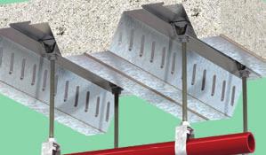
58 Support Fixings 4 Support Fixings Lindapter provides easy-to-install solutions for supporting building services from structural or secondary beams, including: the suspension of HVAC equipment, pipe work, fire protection/sprinkler systems, suspended ceilings and electrical equipment. The range of high quality connections are extremely adjustable, allowing the fast alignment of pipes etc. for a quick, cost effective installation. As with all Lindapter connections, safety is paramount and where appropriate, independent approvals include VDS and FM for fire protection applications. Please note, for the installation of heavy duty pipe supports such those of the petrochemical industry, the steel connections in Section 1 of this catalogue are more suitable. For more information, please contact Lindapter who will be pleased to design a connection to your specific requirement. 58

59 Type FLS Support Fixings 4 Type FLS High Grade Alloy Steel, bright zinc plated Setscrew Locknut Nut Basket T Swivel Unit W X U R 360º A flange clamp with a swivel unit for parallel and sloping flanges. Supplied with a high tensile setscrew for secure grip. Y Safe Working Load (4:1 Factor of Safety) Tightening Torque Product Thread Tensile/ 25º Tensile/> 25º to 45 Clamping Thickness Setscrew Setscrew Nut Dimensions Code Y W N R T U X Width kn kn mm Nm Nm mm mm mm mm mm FLS08 M M FLS10 M M Order example: FLS08 Installation Approved Applications N M S Locate FLS onto flange. 2. Ensuring lug on locknut locates into main body, tighten down setscrew (), and then tighten upper locknut (N). 3. Install threaded rod by screwing into nut located in nut basket (S). Ensure full thread capture. 4. Secure assembly in nut basket (S) from beneath using a locknut (not supplied). General Applications Parallel Flanges only 90 Ensure that the cup point setscrew always grips on the tapered side of the flange

 Thickness screw screw nut Dimensions Clear Tapped Y Y Tensile W N T U X Width V mm kn mm")
60 Type FL Support Fixings 4 Type FL Malleable iron, bright zinc plated *FL210 and FL310 only * Hexagon Setscrew Locknut T N V W U X Y A flange clamp suitable for use with parallel or tapered flange beams, supplied with the back hole drilled or tapped. The type FL uses a hexagon head, high tensile cup point setscrew for secure grip. Can be used with type SW Swivel Unit (see page 51) when connecting to inclined sections. Safe Working Load Tightening Torque (4:1 Factor Clamping Set- Set- Lock- Product Code Hole Ø Thread of Safety) Thickness screw screw nut Dimensions Clear Tapped Y Y Tensile W N T U X Width V mm kn mm Nm Nm mm mm mm mm FL106D FL106T 7 M M FL108D FL108T 9 M M FL210D FL210T 11 M M FL312D FL312T 13 M M FL412D FL410T 13 M M Order example: FL210D with Hex Setscrew Installation 1. Slide FL onto beam flange and tighten setscrew to recommended torque. Guideline: tighten the setscrew finger tight and then apply a further quarter turn (90 ) with spanner. 2. Tighten the locknut (N) to the recommended torque. On tapered flanges the cup point setscrew has to grip on the inside of the flange. 60

 Clamping Thickness Setscrew Setscrew")


61 Type LC / Type SW - Swivel Unit Support Fixings 4 Type LC Malleable iron, bright zinc plated Setscrew Locknut Main Body T N V W Y X U A flange clamp with tapped holes in position X and Y to accept threaded rod or cable clips. For parallel or tapered flanges. Supplied with a high tensile cup point setscrew. Installation see page 56 type FL Safe Working Load Tightening Torque Product Thread (4:1 Factor of Safety) Clamping Thickness Setscrew Setscrew Locknut Dimensions Code X Y Tensile / in Pos. X Tensile / in Pos. Y W N T U Width V kn kn mm Nm Nm mm mm mm LC06 M6 M M LC08 M8 M M Order example: LC06 Type SW - Swivel Unit High Grade Alloy Steel, bright zinc plated * Type FL** *Type FL and SW only Type 10** U R V **supplied separately Swivel unit for applications on inclined beams. Can be used with type FL or type 10. Supplied complete with grade 8.8 M10 x 90 setscrew and nut. Safe Working Load Dimensions Product (4:1 Factor of Safety) Max. Tightening With Bolt Code Rod Tensile Inclination Rotation Torque U R Width V kn Nm mm mm mm SW10 M Order example: SW10 61


62 Type F3 / Type F3-BICC Support Fixings 4 Type F3 Malleable iron, hot dip galvanised Nut Single Leg Bolt Double Leg T V R S W X V A two part flange clamp with a large clamping range. The bolt can be substituted with either drop rod or J bolts. Supplied with or without bolt. For parallel flanges only. Product Code Safe Working Load Clamping with without Bolt 4.6 (4:1 Factor of Safety) Thickness Tightening Dimensions Bolt Bolt Tensile W Torque S T V X Width R kn mm Nm mm mm mm mm mm F308NC F308NB M F310NC F310NB M F312NC F312NB M F316NC F316NB M F320NC F320NB M Order example: F308NC Type F3-BICC Malleable iron, hot dip galvanised T Y S V 1 W V 2 X Y A two part flange clamp which fixes claw type cable cleats directly beneath the flange. Supplied with grade 4.6 bolt. For parallel flanges only. Safe Working Load Clamping Product Bolt 4.6 (4:1 Factor of Safety) Thickness Thread Tightening Dimensions Code Tensile W Y Torque T V 1 V 2 X Width S kn mm Nm mm mm mm mm mm F310BICCA M M Order example: F310BICCA 62


63 Type SH / Type HW/HC Support Fixings 4 Type SH Pre-galvanised strip Hanger Nut Y A With hanger nut C B With standard nut A strap hanger carrying FM approval for use in fire sprinkler installations. Supplied with either a standard or a hanger nut. Product Code with with Pipe Nuts Hole Ø Dimensions Hanger Nut Standard Nut Bore Tapped Y A B C mm mm mm mm SH025N SH M8 or M SH032N SH M8 or M SH040N SH M8 or M SH050N SH M8 or M SH065N SH M8 or M Product Code with with Pipe Nuts Hole Ø Dimensions Hanger Nut Standard Nut Bore Tapped Y A B C mm mm mm mm SH080N SH M8 or M SH100N SH M8 or M SH125N SH M SH150N SH M SH200N SH M Order example: SH025N with M10 hanger nut Type HW/HC Malleable iron, bright zinc plated / hot dip galvanised X Hemispherical Washer R W2 W1 L Y 10 Hemispherical Cup For vertical suspension on angled surface of up to 10 swing either side of the vertical. The hemispherical washer (HW) can be used without the cup. Loads are subject to applications, please contact Lindapter. Dimensions Product Code Hemispherical Washer Hemispherical Cup Hemispherical Washer & Cup Hemispherical Washer Hemispherical Cup X W 1 Y W 2 R L mm mm mm mm mm mm HW HW HW10 HC HW12 HC HW16 HC HW20 HC HW24 HC Order example: HC10 BP 63
 for use on inclined purlins. Safe Working Load 1) Product (3:1 Factor of Safety) Tightening Code Purlins Rod Tensile Torque 10 Kingspan M10 0.")
64 Type 10 Support Fixings 4 Type 10 Mild steel - bright zinc plated A purlin clip to suit a large range of purlin sections. Can be used with type SW Swivel Unit (see page 61) for use on inclined purlins. Safe Working Load 1) Product (3:1 Factor of Safety) Tightening Code Purlins Rod Tensile Torque 10 Kingspan M Multibeam 2 & 3 10 Metsec M eta M ) All loads are subject to the strength of the purlin. Multiple fixings must not overload the purlin. See purlin manufacturer's literature. Order example: with SW10 kn Nm Installation
 for use on inclined purlins.")

65 Type HCW30 / Type HCW31 Support Fixings 4 Type HCW30 Pre-galvanised strip A purlin clip suitable for horizontal purlins. Can be used with type SW-Swivel Unit (see page 61) for use on inclined purlins. Safe Working Load Product (3:1 Factor of Safety) Tightening Code Purlins Rod Tensile Torque HCW30 Kingspan M Multibeam 3 kn Nm Installation Order example: HCW Type HCW31 Pre-galvanised strip A universal purlin clip suitable for multiple different applications. Product Order example: HCW31 Safe Working Load (3:1 Factor of Safety) Code Purlin Tensile kn HCW31 Kingspan Multibeam
 Max. Hole at Angle of Code Rod Tensile Purlin Thickness Ø 10º 20º 30º kn mm mm mm mm mm WF10 M10 1.0 4 18 103 94 74 Order example: WF10 Installation 1.")
 must decrease. 2.")
66 Type WF Support Fixings 4 Type WF Mild Steel, bright zinc plated The Webfix WF for a quick installation directly from the web of ed purlins. Safe Working Load Max. Distance X Product (5:1 Factor of Safety) Max. Hole at Angle of Code Rod Tensile Purlin Thickness Ø 10º 20º 30º kn mm mm mm mm mm WF10 M Order example: WF10 Installation 1. Squeeze legs of WF together and push through hole until it snaps into place. 2. Assemble with nut and ensure full thread capture. Hole position for angled purlins 1. X X Canted Purlins: As the angle of backwards cant increases, the maximum allowable distance X (hole centre to bottom edge of purlin) must decrease. 2. Inclined Purlin: The WF adjusts to whatever angle is required. Hole position is not a limiting factor on product installation. 66


67 Typical Applications Support Fixings 4 Type F3 Type WF Type FLS SF001 SF002 SF003 Type HCW31 Type HCW30 Type 10 Type SH Type SH SF004 67

68 Floor Fixings 5 Floor Fixings Lindapter applied their connection concept to steel flooring and invented a range of innovative products making it possible to install checker plate or open bar grating without on-site drilling or welding, for a fast, low cost operation. Access to the underside of the flooring is not required, eliminating the need for costly scaffolding or elevated work platforms. Installation can be carried out quickly and safely from above, often by one person, significantly reducing installation costs. Both the Floorfast & Grate-Fast carry the Lloyd s Register Type Approval in respect of their resistance to shock and vibration. Hot working is not required, creating particular benefits in hazardous environments such as petrochemical and processing industries, while a rapid and cost efficient installation is beneficial in any industry. 68


 Thickness Thickness Hole Ø BP HDG BP HDG Torque Key t d D t 1 mm mm mm mm mm Nm mm FF08 M8 4.")
69 Type FF - Floorfast Floor Fixings 5 Type FF - Floorfast Malleable iron, Stainless Steel Grade 316, bright zinc plated / hot dip galvanised Unique stepped clamping face Socket setscrew 90º 2 20 t t 1 D d 60 The product consists of a malleable iron body casting with a countersunk socket screw. The eccentric stepped web of the casting allows it to lock under the steel, providing full face contact when torque is applied. For thicker flanges, packing pieces can be supplied. Lloyd s Register Type Approval for vibration resistance. A - Nominal Clearance ½ Flange Width 13 Position of hole centres: ½ flange width - ½ A + 13mm Ferrule Countersunk Product Floorplate Flange Countersunk Ø for Bolt Countersunk Depth for Bolt Tightening Hexagon Code Bolt 1) Thickness Thickness Hole Ø BP HDG BP HDG Torque Key t d D t 1 mm mm mm mm mm Nm mm FF08 M FF10 M FF12 M ) In hot dip galvanised (M10 and M12) a slotted countersunk screw is supplied. Order example: FF12 HDG Installation Hot-dip galvanised M10 and M12 versions are supplied 4. with a slotted countersunk screw. 2. Align castings with straight edge parallel to the edge of the plate and hand tighten. 3. Lay floorplate into position 4. Using a hexagon key release the countersunk screw one full turn. 5. Tighten down the countersunk socket screw. Removal Using a hexagon key, give the Type FF one full anticlockwise turn to release connection from the flange


70 Type GF - Grate-Fast Floor Fixings 5 Type GF - Grate-Fast Body: Malleable iron, mechanical galvanised, hot dip galvanised Top Hat: Mild Steel, mechanical galvanised, hot dip galvanised GF10HDG Hex Head Screw Top Hat Bracket Cast Body T A grating connection for rectangular open bar gratings, with superior clamping force from the cast body. GF08 with stainless steel top-hat bracket for GRP grating. GF10HDG hot dip galvanised for corrosion resistance. GF210HDG for use with 30mm width floor grating bars only. Lloyd s Register Type Approval for vibration resistance. W GF08 / GF10HDG W GF210HDG D D min X max X X Product Grating Bar Grating Bar Bar Tightening Across Code Bolt Flange Depth Width Distance Torque Flats T D W X mm mm mm mm Nm mm GF08 1) M GF10HDG 2) M GF210HDG M ) Supplied with socket head cap screw. 2) Supplied with hex head screw. Order example: GF08. Installation 1. Position pre-assembled Grate-Fast with body between grating bars and nose pointing towards the steelwork. The arrows on the top hat bracket should also be pointing towards supporting steelwork and bracket itself resting on the bearing bars. 2. Slide Grate-Fast towards steelwork until nose fits under the beam flange. Where necessary adjust body/screw to approximate flange thickness/grating depth Tighten screw; the Grate-Fast body will automatically rotate until it locks under the bearing bar, with the nose under the flange. Continue tightening to the recommended torque. Note: For GF08 tighten the socket head cap screw with a 6mm hexagon key. For GF10HDG and GF210HDG tighten the hex head screw using a 3 /8" (10mm) socket drive torque wrench. 70

71 Type GF3030 Floor Fixings 5 Type GF3030 Spring Steel, Sheraplex A grating clamp for instant installation requiring no tools. For parallel flanges only. Product Grating Bar Grating Clamping Force at selected Flanges Code Depth Size Clamping Flange Thickness Clamping Thickness Clamping Force / 1 Clamp mm mm mm mm N GF x GF x GF x Order example: GF3030 Installation Position the fixing with the grating bar located between the two tabs on the upper profile, facing towards the supporting steelwork. 2. Apply a downward force to the fixing, so that the lower leg passes through the grating. 3. Apply a downward force to the top of the fixing. The fixing then snaps in to place. If the lower profile contacts the steelwork web, the GF3030 will automatically relocate itself. Removal Using a screwdriver or lever, raise the back of the GF3030 into position shown in diagram 2. Place the lever between the steelwork and lower leg of the fixing and prise GF3030 away from steelwork. Deformed or damaged clamps cannot be re-used. 71
72 Section Details Appendix 6 Advance UKB Dimensions: BS4-1:2005 D B T Designation Mass D B T Serial Size kg/m mm mm mm 1016 x 305 x x 419 x x 305 x x 292 x x 267 x x 254 x x 305 x x 229 x x 178 x x 312 x x 210 x x 165 x Designation Mass D B T Serial Size kg/m mm mm mm 457 x 191 x x 152 x x 178 x x 140 x x 171 x x 127 x x 165 x x 127 x x 102 x x 146 x x 102 x x 133 x x 102 x x 102 x x 89 x x 76 x Permission to reproduce extracts from BS4-1:2005 is granted by BSI. British Standards can be obtained in PDF or hard copy formats from the BSI online shop: or by contacting BSI Customer Services for hard copies only: Tel: +44 (0) , cservices@bsigroup.com 72
73 Section Details Appendix 6 Advance UKPFC Dimensions: BS4-1:2005 Designation Mass D B T Serial Size kg/m mm mm mm 430 x 100 x x 100 x x 100 x x 90 x x 90 x x 75 x x 90 x x 75 x x 90 x x 75 x x 90 x x 75 x x 90 x x 75 x x 65 x x 50 x D B T Advance UKC Dimensions: BS4-1:2005 Designation Mass D B T Serial Size kg/m mm mm mm 356 x 406 x x 368 x x 305 x x 254 x x 203 x x 152 x D B T Use of the Advance name and range of sections by kind permission of Tata Steel. Note: Advance, UKB, UKPFC, UKC and ComFlor are registered trademarks of Tata Steel 73


74 Projects Appendix 6 Steelwork Fixings Project: Country: Product: Application: St Pancras Station, London UK Type AF The connection of a new roof to the existing structure. Cavity Fixings Project: Country: Product: Application: HafenCity, Hamburg Germany Type HB - Hollo-Bolt Flush Fit Connecting the hollow section glazing support frame. Decking Fixings Project: Country: Product: Application: Canary Wharf, London UK Type AW - Alphawedge The suspension of building services from composite decking. Support Fixings Project: Country: Product: Application: Manhattan Bridge, New York City USA Type F3 Pipe support. Floor Fixings Project: Country: Docklands Light Railway, London UK Product: Type FF - Floorfast Application: Securing a maintenance walkway. 74


75 Projects Appendix 6 The Type AF was specified to secure the steel framework of a new roof to the existing structure of the grade 1 listed William Barlow shed at St Pancras Station. In the most crucial part of the refurbishment, Lindapter s high strength clamps avoided drilling or welding, therefore removing the risk of damaging the historic Victorian arches. In this structural steelwork application, the Hollo-Bolt Flush Fit allowed the glass roof and frontage of the Germanischer Lloyd headquarters to be constructed without the fixings being visible, ensuring the construction remained true to GMP s competition winning architectural design. The Type AW Alphawedge, like most Lindapter Composite Decking Fixings, attaches to the dovetail shaped re-entrant channel of steel decking profiles. In this project, pipework, ventilation and lighting systems were suspended from structural steel. Lindapter has a range of fixings compatible with all major decking manufacturers including CMF, Tata Steel, Kingspan, SMD and Richard Lees. Lindapter Support Fixings are often specified for securing pipework due to the ease of installation and high adjustability. In this case, the Type F3 was used to connect a 100mm pipe, carrying fibre optic cable for high-speed internet. No drilling, welding or power was required, simplifying the installation across the 450m span of the iconic Manhattan Bridge. The Type FF - Floorfast contributed to the fast installation of the chequer plate flooring, used to construct maintenance walkways alongside the track of the Docklands Light Railway. Another advantage Lindapter brought to this project is that the fixings are removable, allowing easy maintenance access to signaling and power cables running below the floor plate. 75
 1274 521130 E: enquiries@lindapter.com support@lindapter.com www.lindapter.com LindUKOct11")
76 Lindsay House Brackenbeck Road Bradford West Yorkshire BD7 2NF England T: +44 (0) F: +44 (0) E: LindUKOct11
Available from. Established Technical Innovation in Steelwork Connections
 Established 1934 Technical Innovation in Steelwork Connections 2 Introduction to Lindapter Welcome For over 80 years Lindapter has earned a respected reputation as the pioneer in the design and manufacture
Technical Innovation in Steelwork Connections
 Established 1934 Technical Innovation in Steelwork Connections 2 Introduction to Lindapter Welcome For over 80 years Lindapter has earned a respected reputation as the pioneer of designing and manufacturing
Technical Innovation in Steel Connections
 Technical Innovation in Steel Connections USA & Canada Catalog Established 1934 Lindapter - Technical Innovation in Steel Connections 2 inquiries@lindapterusa.com www.lindapterusa.com For more than 75
Tel: +44 (0)
") 4 Lindapter s support fixing range offers a series of ideal solutions for all building services. This includes the suspension of HVAC equipment, pipe work, fire protection/sprinkler systems, suspended
4 Lindapter s support fixing range offers a series of ideal solutions for all building services. This includes the suspension of HVAC equipment, pipe work, fire protection/sprinkler systems, suspended
Steel Floor Connections
 Steel Floor Connections Pioneering high strength steel connections since 1934 2 Steel Floor Connections by Lindapter Welcome For over 80 years Lindapter has earned a respected reputation as the pioneer
Composite Decking Fixings 3
 Composite Decking Fixings 3 Composite Decking Fixings Lindapter composite decking fixings have all been designed in conjunction with the various decking manufacturers to ensure they fulfil the necessary
Cone. Bolt. Rubber Washer. Rubber Washer. compressed / increased clamping force
 Type HB - Hollo-Bolt Cavity Fixings 2 Type HB - Hollo-Bolt Steel, bright zinc plated plus JS 500 Steel, hot dip galvanised Stainless Steel Grade 316 Collar Sleeve Cone Bolt Suitable for hollow sections,
Hollo-Bolt. High Clamping Force (HCF) M8 M10 M12 M16 M20 JS500 Stainless Steel Sheraplex Hot Dip Galv.
 M8 M10 M12 M16 M20 JS500 Stainless Steel Sheraplex Hot Dip Galv.") Type HB - Hollo- Type HB - Hollo- Steel, bright zinc plated plus JS5 Steel, sheraplex Steel, hot dip galvanised (Hex Head only) Stainless Steel Grade 316 Hollo- Suitable for hollow sections, tubes and
Type HB - Hollo- Type HB - Hollo- Steel, bright zinc plated plus JS5 Steel, sheraplex Steel, hot dip galvanised (Hex Head only) Stainless Steel Grade 316 Hollo- Suitable for hollow sections, tubes and
The Original Expansion Bolt for Structural Steel. Hollo-Bolt
 The Original Expansion Bolt for Structural Steel Now marked by 2 WELCOME THE ORIGINAL EXPANSION BOLT FOR STRUCTURAL STEEL Lindapter, the steelwork connection specialists, invented the as a fast, cost effective
Hollo-Bolt. The Original Expansion Bolt for Structural Steel ALLFASTENERS. Your trusted Australian supplier. Available
 Available WWW.ALLFASTENERS.COM.AU ALLFASTENERS. The Original Expansion Bolt for Structural Steel Now marked Hollo-Bolt by 2 WELCOME Call 1800 255 349 THE ORIGINAL EXPANSION BOLT FOR STRUCTURAL STEEL Lindapter,
5-axis clamping system compact
 5-axis clamping system compact 395 5-axis clamping system compact Function We are setting standards with the new KIPP 5-axis clamping system compact in this field. The system was specifically designed
Products for fixing to Steelwork and Decking
 Products 8.0 Beam Clamp - Single Support 8.1 Universal Joint for any variable Angle Adjustment 8.2 Beam Clamp TCS for Header Rails 8.3 Beam Clip for Cross Support/ Dimensioning of Bolts 8.4 Beam Clip for
Technical Innovation in Steelwork Connections
 Technical Innovation in Steelwork Connections Available from Established 1934 Lindapter - Technical Innovation in Steelwork Connections 2 For more than 75 years, Lindapter has earned a respected reputation
MEFA mounting accessories
 MEFA mounting accessories Mounting accessories Base plates Page 5/2 Double holder Page 5/4 Height-adjustable suspensions Page 5/5 Pendular bolt joints Page 5/6 Trapeze hanger Page 5/7 Threaded hooks, distance
Adjustable Feet Castors Accessories for Floor Elements
 Adjustable Feet Castors Accessories for Floor Elements Products in this section Levelling Knuckle Feet Threaded spindles for infinite height adjustment Metal or plastic foot plate Knuckle Feet X Compatible
Khathij Industrial Fasteners
 Dear Sir/Madam, Khathij Industrial Fasteners This is Saqubar Sadique representing 'KHATHIJ INDUSTRIAL FASTENERS' from Chennai, India. We 'Khathij industrial fasteners' like to introduce us as a Stockist
PENSTOCK VALVES. Performance through Excellence
 VALVES & MANUFACTURING (1988) LTD. PENSTOCK VALVES Performance through Excellence SLIDEGATES WEIR GATES STOP LOGS SLIDEGATES PRECISION FACE SEALING VALVES WEIR GATES STOP LOGS SLIDEGATES Actuation Installation
Tel / (USA & CANADA) /
 /") Tel.58.847 / 8.388.459 (USA & CANADA) / Email sales@msdiscounttool.com MULTIPURPOSE CLAMPS - USA SERIES 7: Lightweight and 4% stronger than C clamps. Floating jaws that always stay parallel. Designed to
Tel.58.847 / 8.388.459 (USA & CANADA) / Email sales@msdiscounttool.com MULTIPURPOSE CLAMPS - USA SERIES 7: Lightweight and 4% stronger than C clamps. Floating jaws that always stay parallel. Designed to
Simotec. 13.i
 Products: Framo 80 13.0 Products: Framo 80 13.1 Products: Structural Elements 100/120 13.2 Products: Pipe Shoes 13.3 Framo 80: Beam Section and Screw 13.4 Framo 80: Cantilever Bracket and End Support STA
ALUMINUM PIPE GUIDERAIL 01/01/
 NOTES PIPE RAILING & POSTS: Structural Tube, Pipe and Bar shall be in accordance with ASTM B22 or ASTM B429, Alloy 606-T6. End Rail 90 bends and corner bends with maximum 4-0" post spacing, may be Alloy
S-BT screw-in stainless steel and carbon steel threaded studs
 S-BT screw-in stainless steel and carbon steel threaded studs Product data Dimensions S-BT-MR M10/15 SN 6 S-BT-MR M10/15 SN 6 AL**) S-BT-MR W10/15 SN 6 S-BT-MR W10/15 SN 6 AL**) S-BT-MR M10/15 SN 5 ***)
STEEL PIPE GUIDERAIL 01/01/
 NOTES PIPE RAILING & POSTS: Pipe Rails and s shall be in accordance with ASTM A5 Grade B for standard weight pipe and ASTM A500 Grade B, C or D or ASTM A50 for structural tube. Bars for handrail supports
Clamping devices 521
 Clamping devices 521 522 Product overview Clamping devices Adjustable straps K0001 Hook clamps K0012 Goose-neck straps with long slot K0002 Page 526 Hook Clamps with collar K0013 Page 535 Equipped clamps
Clamping bolts Eccentrical cams clamping units
 2.3 Shaft Clamping bolts Eccentrical cams clamping units 2.9 2.8 2.7 2.6 2.5 2.4 2.3 2.2 2.1 2.3 Clamping bolts, Eccentrical cams, Shaft clamping units Page 641 2.3 Clamping bolts, Eccentrical cams, Shaft
connecting the world PDF compression, OCR, web optimization using a watermarked evaluation copy of CVISION PDFCompressor
 C O N S T R U C T I O N I W I N D E N E R G Y I T U N N E L L I N G I R A I L I O E M connecting the world the tunnelling market Tunnelling is a key facet of infrastructure development particularly where
Design Guide for Hot Dip Galvanizing best practice for venting and draining
 Design Guide for Hot Dip Galvanizing best practice for venting and draining Contents Introduction 3 Handrails/ 25 Balustrades Importance 4 of Venting and Draining Purpose Safety Quality Aesthetics General
Beam and Purlin Clamps Beam Clamps
 Metal Framing & Cable Tray Steel City Hangers, Clamps & Fasteners Beam and Purlin Clamps Beam Clamps Fits beam flanges to 2" Supports 4" and 8" threaded rod, S-hooks, electrical boxes, conduit and bridle
Installation Systems INSTALLATION SYSTEMS
 INSTALLATION SYSTEMS 230 MM Channel System MM Channel System Page 230-237 MQ Channel System MQ Channel System Page 237-248 MC Channel System MC Channel System Page 249 Accessories Beam Clamp MAB Page 249
Standard CATALOGUE 2018
 Standard Clamping Elements CATALOGUE 2018 Company history 1890 Company founded as a lock manufacturer by Andreas Maier. 1920 Product range extended to include spanners. 1928 Production line assembly of
GAGING AND INSPECTION
 Fixture Plates...75 Fixturing Towers...76 CMM Fixturing Kits... 77-78 Clamping Components... 79-80 Standoffs and Locators... 81-82 Magnetic Components... 83-84 Height Adjustment...84 Positioners...85 Clamp
Leveling Feet, Base Plates and Casters
 Leveling Feet, Base Plates and Casters 77 Leveling Foot 1 1 Fastening to profile end Fastening in T-slot of profile For leveling tables and light equipment. Ratchet-type height adjustment requires no tools.
Kee Gate Operation & Maintenance Manual
 R E L I A B L E S A F E A C C E S S Kee Gate Operation & Maintenance Manual 2 Kee Gate System Overview KEE SAFETY S SAFETY GATES KEE GATE is a complete range of safety gates designed specifically to provide
EURO-BEARINGS LTD COMBINED ROLLER BEARINGS & MATING STEEL PROFILES
 EURO-BEARINGS LTD & MATING STEEL PROFILES For fork lift trucks, overhead cranes, track conveyors and heavy duty linear motion systems... The axial (side thrust) roller runs on the web of the channel whilst
The Original Expansion Bolt for Structural Steel. Hollo-Bolt
 The Original Expansion Bolt for Structural Steel Hollo-Bolt 2 WELCOME THE ORIGINAL EXPANSION BOLT FOR STRUCTURAL STEEL Lindapter, the steel connection specialists, invented the Hollo-Bolt as a fast, cost
1. TOOLS + MATERIALS REQUIRED
 R INSTALLATION INSTRUCTIONS PRODUCT: BALDUR + ODEN CONFIGURATION: BI-PARTING DOOR MOUNT: TOP MOUNT Product is covered by U.S. patents. For more information visit www.krownlab.com. TOOLS + MATERIALS REQUIRED
Precision Engineering & Reliability WIRE ROPE SUSPENSION SYSTEM
 Precision Engineering & Reliability WIRE ROPE SUSPENSION SYSTEM DobyGrip Wire with Loop Quick and easy fixing to purlins, beams etc by forming a choke knot. Reduces the installation time compared to conventional
Components made of special materials. Floor Elements for Profile St Profile KH. Fastening Elements for Profile KH
 Profile Fastening Elements for Profile Floor Elements for Profile Profile KH Fastening Elements for Profile KH Components made of special materials Products in this section Profile 8 x eel profile that
STAR TOOL SUPPLY / GRAND TOOL SUPPLY
 MULTIPURPOSE CLAMPS - USA SERIES 7: Lightweight and 4% stronger than C clamps. Floating jaws that always stay parallel. Designed to eliminate distorting or twisting action. Cantilever action provides 4:
Single and Double Gates Operation & Maintenance Manual
 R E L I A B L E S A F E A C C E S S Single and Double Gates Operation & Maintenance Manual System Overview SAFETY GATES KEE GATE is a complete range of safety gates designed specifically to provide permanent
PEC-TA Cast-in Channels and Bolts. Certified German quality for high-end fixing solutions. Advantages of using PEC Cast-in Channels.
 Fixing Technology s and Bolts PEC Cast-in Channels are ideally suited for quick, reliable and cost-efficient fixing of different construction elements. The possibility of making simple and flexible adjustments
DobyGrip Accessories. Wire with Loop. Wire with Closed M6 & *M8 Eye Bolt. Wire with Carabina
 Wire with Loop Quick and easy fixing to purlins, beams etc by forming a choke knot. Reduces the installation time compared to conventional methods of suspension. All wires are supplied including the DobyGrip
SWAY BRACE PIPE ATTACHMENT FIG. 010
 Function: Designed for bracing pipe against sway and seismic disturbance. The pipe attachment component of a sway brace system used in conjunction with a PHD Manufacturing structural attachment fitting,
BEST PRACTICE GUIDE. Socket Bases. Working with Concrete Slabs
 Working with Concrete Slabs When working with concrete slabs the barrier protection can be erected in three ways - with socket bases, adjustable slab edge brackets and multi slab clamps. Socket Bases 1
Fixings & Fastenings. Bright Zinc Plated, Galvanised & Stainless Steel. Lockinex. ea i, ea u i
 Fixings & Fastenings Bright Zinc Plated, Galvanised & Stainless Steel Lockinex ea i, ea u i INTRODUCTION The Lockinex Range of Fixings & Fastenings are manufactured in Bright Zinc Plate, Hot dipped galvanised
PRODUCT: LOKI INSTALLATION INSTRUCTIONS. Product is covered by U.S. patents. For more information visit
 R INSTALLATION INSTRUCTIONS PRODUCT: LOKI CONFIGURATION: SINGLE DOOR MOUNT: GLASS MOUNT Product is covered by U.S. patents. For more information visit www.krownlab.com . TOOLS + MATERIALS REQUIRED TOOLS
VACUSEAL MODEL 200. HOT TUB PRODUCTS 233 Carrington Road Bethany CT
 VACUSEAL MODEL 200 J G F G H L HOT TUB PRODUCTS 233 Carrington Road Bethany CT 06524 860-469-2580 www.vacusealcoverlift.com www.hottubproducts.com Made in USA H K E D C I A P B 10 9 8 7 6 5 4 3 2 1 0 SPAS
Roller Guides C-Rail Systems Linear Guide Systems Ball-Bearing Guide Bushes Ball-bush block guides Shafts Accessories for Linear Slides
 Roller Guides C-Rail Systems Linear Guide Systems Ball-Bearing Guide Bushes Ball-bush block guides Shafts Accessories for Linear Slides Application example linear systems, drives and accessories 1 2 3
Fig. 2 DORMA-Glas Stand/Issue 02/03 Seite/Page 1/7
 FSW Installation instructions Track rail 75 x 72 mm 1. Ceiling substructure and installation of the track rail (Fig. 1): The track rail must be bolted over its entire length (including the stacking track
Notes. Modifications and constructional corrections arising particularly from technological development excepted.
 Notes Our service staff and application en gineers will be pleased to offer you their assistance to answer your questions or to work out in cooperation with you specific solutions with the aid of our own
VACUSEAL MODEL 300 & 400
 VACUSEAL MODEL 300 & 400 G L HOT TUB PRODUCTS 2 Toelles Road, Suite 13 Wallingford, CT 06492 860-469-2580 www.hottubproducts.com J G F H H K E D C I A P B 10 9 8 7 6 5 4 3 2 1 0 0 1 Figure 1 2 3 4 SPAS
Copper Tubing Hangers Clevis Hangers. Copper Tubing Hangers
 Copper Tubing Hangers Clevis Hangers Copper Tubing Hangers Fig. CT-69 Adjustable Swivel Rug Fig. CT-138R Fig. CT-65 Fig. CT-109 Extension Split Light Weight Adjustable Clevis Fig. CT-99 & CT-99C Split
INSTALLATION MANUAL IOWA MOLD TOOLING CO., INC. BOX 189, GARNER, IA MANUAL PART NUMBER:
 PARTS-1 Model 24562/28562 Crane INSTALLATION MANUAL IOWA MOLD TOOLING CO., INC. BOX 189, GARNER, IA 50438-0189 641-923-3711 MANUAL PART NUMBER: 99903701 Iowa Mold Tooling Co., Inc. is an Oshkosh Truck
Single and Double Gates Operation & Maintenance Manual
 R E L I A B L E S A F E A C C E S S Single and Double Gates Operation & Maintenance Manual 2 System Overview SAFETY GATES KEE GATE is a complete range of safety gates designed specifically to provide permanent
MATERIAL AND EQUIPMENT STANDARD FOR METRIC TYPE FASTENERS (SCREWS, BOLTS, STUDS, NUTS AND WASHERS) ORIGINAL EDITION DEC. 1997
 ORIGINAL EDITION DEC. 1997") MATERIAL AND EQUIPMENT STANDARD FOR METRIC TYPE FASTENERS (SCREWS, BOLTS, STUDS, NUTS AND WASHERS) ORIGINAL EDITION DEC. 1997 This Standard is the property of Iranian Ministry of Petroleum. All rights
MATERIAL AND EQUIPMENT STANDARD FOR METRIC TYPE FASTENERS (SCREWS, BOLTS, STUDS, NUTS AND WASHERS) ORIGINAL EDITION DEC. 1997 This Standard is the property of Iranian Ministry of Petroleum. All rights
REISSER-Schraubentechnik GmbH THE RELIABLE CONNECTION
 REISSER-Schraubentechnik GmbH THE RELIABLE CONNECTION REISSER-Schraubentechnik GmbH // Production and company headquarters in Ingelfingen Criesbach Fritz-Müller-Str. 10 74653 Ingelfingen Criesbach Germany
The company. Heule warehouse: Quarto plates, fasteners, fittings and industrial ironware.
 The company Heule warehouse: Quarto plates, fasteners, fittings and industrial ironware. Offices: your contact persons will be glad to be of assistance. Kuurne warehouse: Bars, sheets and plates, tubes
Superstrut. Metal Framing. Beam Clamps. Design Loads. Finishes and Special Materials
 Loads Where design loads are indicated, they provide for a safety factor of 3 in conformance with the merican Standard Code for Pressure Piping. For more information, see page 57 for Engineering Data and
Installation Instructions Universal Crossmember Kit - 60 Track Width BEFORE Measure Twice, Weld Once! II
 Installation Instructions Universal Crossmember Kit - 60 Track Width Please read these instructions completely BEFORE starting your installation. Remember the basic rule for a successful installation:
Scaffolding ACCESSORIES
 Scaffolding ACCESSORIES INITIA COMPONENTS FIXED BASE For flat surfaces. With holes in the spigot for attaching the cradle head. The reinforced base plate has a thickness of 5 mm and a surface area of 120
PART MATERIALS. Section Fencing Materials. Description
 PART 03000 - MATERIALS Section 03010 - Fencing Materials Description 03010.00 Scope - This section consists of the test requirements, specifications and tolerances for barbed wire, woven wire and chain
Stargrip series 3000 Mechanical Joint Wedge Action Restraint for Ductile Iron Pipe
 Stargrip series 3000 Mechanical Joint Wedge Action Restraint for Ductile Iron Pipe INFORMATION The Stargrip Mechanical Joint Restraint System is a unique product with a proven design that provides an exceptional
INTERPLANT STANDARD STEEL INDUSTRY CODE OF PRACTICE FOR CLAMPING OF CRANE RAILS
 INTERPLANT STANDARD STEEL INDUSTRY CODE OF PRACTICE FOR CLAMPING OF CRANE RAILS IPSS:1-8-17-14 (First Revision) Corresponding IS does not exist Formerly: IPSS:1-8-17-97. FOREWORD.1 This Interplant Standard
CONTENTS. Hammerscrews White Zinc Plated 2 Hammerscrews Stainless Steel A Nylon Frame Anchors Yellow Zinc Plated 3 Nylon Plug 3
 C CONTENTS CONTENTS PAGE 1 HAMMERSCREWS Haerscrews White Zinc Plated 2 Haerscrews Stainless A2-304 2 2 NYLON FRAME ANCHOR Nylon Frame s Yellow Zinc Plated 3 Nylon Plug 3 3 WINDOW FRAME ANCHOR Window Frame
Segmental ring types provided by F P McCann: Segments in stock are front bolted. Back bolted segments are available to order: Cross joint Corbel Ring
 Building Manual for F P McCann `Smoothbore Shaft Linings with EPDM Gaskets (rev 04) (To be read in conjunction with the Segmental Shaft and Tunnel Safety Data Sheet) Segmental ring types provided by F
Important Note. Tools Required: Welder capable of fully welding 10 GA.135 steel
 INSTALLATION INSTRUCTIONS Frame Reinforcement Kit 11100 (Patent Pending) 1968-72 GM A-Body Coupe/Sedan Read Instructions FULLY before starting Installation Important Note Installation of this kit requires
Composition of kit SC3140 SC3110 SC3100 SC3140 SC3120. KF-SC31-R0_EN PAGE 2 of 15. max mm. max. 100 kg. 10 mm
 Composition of kit SC3140 SC3100 SC3140 SC3120 max. 100 kg 10 mm max. 2700 mm KF-SC31-R0_EN PAGE 2 of 15 important information KF-SC31-R0_EN PAGE 3 of 15 DIAGRAM OF WALL OPENING AND CROSS-SECTION Lv LG
CSS Central Mount System
 CSS-20 Installation Manual CSS-20 Safety Notifications Below are the installation instructions for the CSS-20-2 Long Span Beam Mounting System. Please read these safety notifications prior to beginning
Lichtgitter Perforated Metal Planks
 Forge-welded gratings Pressure-locked gratings Perforated metal planks GRP gratings Chequer plates Spiral staircases Staircases Ladder rungs Steel Service Hot dip galvanising Lichtgitter Perforated Metal
PRESENT, FORD TRANSIT, 148 WHEEL BASE ROCKER GUARDS
 4031 2013-PRESENT, FORD TRANSIT, 148 WHEEL BASE ROCKER GUARDS Version 1.0 General Notes For the most up to date and current instructions, please visit our website at www.vancompass.com Please read all
Technologies, Inc. Installation Instructions for Anchors & Components. Rev PAGE 1 / 11
 Installation Instructions for Anchors & Components PAGE 1 / 11 GROUND ANCHOR INSTALLATION INSTRUCTIONS NOTE: 1) The tensioning bolt can be inserted in the head from either side. 2) In areas of severe cold
Mission Statement. State Steel strives to provide quality products and services at competitive
 Mission Statement State Steel strives to provide quality products and services at competitive prices. This commitment is demonstrated with several branch locations all offering large, diverse inventories
AVK High Strength Blind Threaded Fasteners. Ideal for blind applications
 High Strength Blind Threaded Fasteners Ideal for blind applications AVK Spinwall Technology How Hole Fill Works For You As the AVK insert is installed, the knurled body expands 360 to create hole fill.
SECTION METAL FABRICATIONS
 SECTION 05100 PART 1 - GENERAL 1.01 DESCRIPTION A. Section includes specifications for metal fabrications, including minimum requirements for fabricator, and galvanizing. 1.02 REFERENCE STANDARDS A. ASTM
Single and Double Gates Operation & Maintenance Manual
 R E L I A B L E S A F E A C C E S S Single and Double Gates Operation & Maintenance Manual System Overview SAFETY GATES KEE GATE is a complete range of safety gates designed specifically to provide permanent
MPA-9000 Universal Ceiling Projector Mount Kit
 I N S T R U C T I O N M A N U A L Universal Ceiling Projector Mount Kit The Universal Ceiling Projector Mount provides a unique, simplified method of ceiling mounting your inverted projector. This low
101B, 210X, ELM, VSTB Installation Manual
 101B, 210X, ELM, VSTB Installation Manual 99-16105-I001 Copyright 2010 by ALL rights reserved. Information in this document is subject to change without notice. Companies, names and data used in examples
Swifts cable ladder supports
 heavy duty cantilever arms Heavy duty cantilever arms enable horizontal runs of cable ladder to be mounted to vertical steel, concrete or masonry surfaces or to Swiftrack channel. They are suitable for
No. 412, 414, 416 Operations Manual
 No. 412, 414, 416 Operations Manual CARE: Occasional oiling of moving parts with machine oil will ease operation and extend the life of the brake. Occasionally check and tighten the lower beam bracket
Mounting systems for solar technology
 Mounting systems for solar technology ASSEMBLY INSTRUCTIONS Crosshook 3S CrossHook 4S GB Table of contents TABLE OF CONTENTS THE COMPANY SAFETY REGULATIONS MATERIALS REQUIRED TOOLS REQUIRED ASSEMBLY 2
#2010 #1795. Frame Rack Dyna Mo Clamps Two pair of jaws with 12 draw bar. Grip surface 9-¼ wide. #1929 #1910
 Mity Bite Clamp Use for one or two-directional pulling. Good for confined areas. Grip 2 wide. Multi Angle Clamp Pulls from any direction with a 180 arc. Makes two-way pulling faster and easier. Bolt stoppers
MATERIAL COMBINATION NUMBER 2: Corrosive environment requiring harder, wear-resistant seating faces and resistance to dezincification.
 Cast Iron Slide Gates Spec Sheet General The contractor shall furnish and install the following cast iron slide gate assemblies as listed on the Gate Schedule and detailed on the manufacturer s drawings.
AIR MASTER SYSTEMS INSTALLATION GUIDE TABLE OF CONTENTS
 AIR MASTER SYSTEMS INSTALLATION GUIDE TABLE OF CONTENTS GENERAL INFORMATION...1 Freight Damage... 1 Repairing Paint Scratches...1 BASE CABINETS... 2 Drawer Removal and Reinstallation...2 Replacing Drawer
HEICO FASTENING SYSTEMS. Simple Fast Reliable HEICO-TEC TENSION NUT
 HEICO FASTENING SYSTEMS Simple Fast Reliable HEICO-TEC TENSION NUT WWW.HEICO-TEC.COM HEICO-TEC TENSION NUT SIMPLE FAST RELIABLE For a secure joint with a HEICO-TEC tension nut, no electric, hydraulic,
Barofor Round System (polyester coated) Panels, Posts, Accessories
 Panels, Posts, Accessories") 1 Scope This Technical Data Sheet specifies the requirements for the Barofor Round System. The complete system exists of: Panels Posts Accessories such as fixation system and posts caps. Panels and posts
1 Scope This Technical Data Sheet specifies the requirements for the Barofor Round System. The complete system exists of: Panels Posts Accessories such as fixation system and posts caps. Panels and posts
INSTRUCTION MANUAL Q-HYDRAULIC
 Dat: 15.04.02 No: 94-BA 5039E/1b TABLE OF CONTENTS Part III 3.0 Type code explanation 3.1 Service connections 3.2 Impeller clearance adjustment 3.2.1 Wear of wearing parts 3.2.2 General notes to adjustment
Delrin Cone T-Handle Spring Stop w/pad...9 Screw Jack Large Toggle Clamp w/pad...9 Adjustable Ball Positioner...14
 Distributed by Rapp Industrial Sales INDEX Aluminum Fixture Plates...4 Pin Rest...11 Acrylic Plates...4 Thread Adapter...11 Fixturing Towers...5 Delrin Cone...11 CMM Fixturing Kits...6-7 Magnetic Rest
LY5005/ LY5007/
 LY5005/3300-000-010 LY5007/3300-000-020 Operation/Maintenance Manual For Parts or Technical Assistance 800-327-0770 Table of Contents Style LY5005 & LY5007/3300-000-010 & 3300-00-020 2-3 Drive Rod Assembly
T-Slot Clamps Rotagrip Ltd Tel Website
 T-Slot Clamps 12150 Body: heat treated steel. Clamp: brass. Packed in pairs. For use in T-slots of machine tables. For replacement clamping screws see 12112. Hex. key not included. Order No. Slot size
Expanded Metal Walkway
 Expanded Metal Walkway GRIDWALK WALKWAY GRIDWALK WALKWAY GRIDWALK (WK) Mesh Reference Standard Nominal Sheet Sizes () LW Nominal Size of Mesh () SW Nominal Size of Mesh Opening () Approx. Strand Size ()
Carousels - Overlapping Slat
 Carousels - Overlapping Slat Introduction The overlapping slat carousel is designed to re-circulate baggage through a series of rectangular shaped slats overlapped and linked to form a continuous loop.
NEWS Part. N /0 MINITEC NEWS
 NEWS 2009 Part. N 95.0423/0 MINITEC NEWS 2009 1 TABLE OF CONTENT INTRODUCTION CONTENTS 3 END CAP Z WITH HAMMER TAPS 3 END CAP 45X45 VA 4 ANGLE 25 GD-Z 4 ANGLE 45X90 GD-Z 5 ANGLE 90 GD-Z 5 HINGE 19 S 6
PUSH-PULL-PROPS. and accessories ROBUSTA-GAUKEL GMBH MOUNTING TECHNOLOGY &CO.KG
 PUSH-PULL-PROPS and accessories MOUNTING TECHNOLOGY ROBUSTA-GAUKEL GMBH &CO.KG MOUNTING TECHNOLOGY PUSH-PULL-PROPS AND ACCESSORIES INDEX General information...................... 3 Push-pull-prop Type
Proposal for new standard. Determination of interface friction between painted parts. Orientation. p. 1 (15) Draft1, Revised
 Draft1, Revised") p. 1 (15) Draft1, Revised 2018-03-29 Proposal for new standard Determination of interface friction between painted parts. Orientation This standard specifies the method and conditions to evaluate interface
p. 1 (15) Draft1, Revised 2018-03-29 Proposal for new standard Determination of interface friction between painted parts. Orientation This standard specifies the method and conditions to evaluate interface
KEEP YOUR RESOURCE MOVING.
 LINER BOLTS KEEP YOUR RESOURCE MOVING. COLUMBUS McKINNON CORPORATION Leading the Industry Downtime in the grinding mill operation is caused by one of two things: regularly scheduled maintenance or unscheduled
thoroughly tried and tested! EWE Tapping Valves A single system for all types of pipes
 thoroughly tried and tested! EWE Tapping Valves A single system for all types of pipes www.ewe-armaturen.de EWE Tapping Fittings high-quality products from Germany EWE tapping fittings are the product
STEEL CONSTRUCTION FASTENERS STEEL CONSTRUCTION FASTENERS
 STEEL CONSTRUCTION FASTENERS STEEL CONSTRUCTION FASTENERS 1 STEEL CONSTRUCTION FASTENERS 2 STEEL CONSTRUCTION FASTENERS Contents New Construction Products Regulation (CPR) 5 1. High strenght structural
Bumper Sign INSTALLATION INSTRUCTIONS
 Bumper Sign INSTALLATION INSTRUCTIONS BUMPERSIGN TOOL CHECKLIST SDS MAX Rotary Hammer Drill Marker/Pencil SDS MAX 1 Carbide Drill Bit Tape Measure Torque Wrench with ½ Drive Power Source Vacuum ½ Drive
Single and Double Gates Operation & Maintenance Manual
 R E L I A B L E S A F E A C C E S S Single and Double Gates Operation & Maintenance Manual 2 System Overview SAFETY GATES KEE GATE is a complete range of safety gates designed specifically to provide permanent
Testing of friction properties of fasteners
 2018-02-13 Sida 1 (31) Testing of friction properties of fasteners Contents 1 Introduction 2 2 Scope 2 3 Terms and definitions 3 4 Structure of evaluation of friction properties 5 5 Cleaning of test parts
TANDEM plus BLUMOTION
 TANDEM plus BLUMOTION Premium Concealed Runners for Wood Drawers TANDEM plus BLUMOTION TANDEM plus BLUMOTION brings together all of the features, innovations and benefits that Blum has developed since