READ THIS FIRST. Phone #: (360) Tech Support: Web:
|
|
|
- Evangeline Chase
- 5 years ago
- Views:
Transcription
1 READ THIS FIRST Model W1741S ***IMPORTANT UPDATE*** Applies to Models Mfd. Since 4/15 and Manual Insert Revised 5/08 Phone #: (360) Tech Support: Web: We made the following changes to this machine since the manual insert was printed: Changed spiral cutterhead and indexable inserts. Aside from the information contained in this update, all other content in the owner's manual is applicable and MUST be read and understood for your own safety. IMPORTANT: Keep this update with the owner's manual for future reference. If you have any further questions, contact our Technical Support. Revised Parts V V2 REF PART # DESCRIPTION 162V2 X1741S162V2 SPIRAL CUTTERHEAD V V2 X1741S164V2 INDEXABLE INSERT 14 X 14 X 2 V #17655MN COPYRIGHT SEPTEMBER, 2015 BY WOODSTOCK INTERNATIONAL, INC. WARNING: NO PORTION OF THIS MANUAL MAY BE REPRODUCED IN ANY SHAPE OR FORM WITHOUT THE WRITTEN APPROVAL OF WOODSTOCK INTERNATIONAL, INC. Printed in China
2 MODEL W1741 8" x 76" 4-KNIFE CUTTERHEAD PARALLELOGRAM JOINTER Specifications Motor: 3 HP, 240V, 1-Ph, 60 Hz, 15A To reduce the risk of serious injury when using this machine: Cutterhead: 4-Knife, 3-3/16 Dia. 1. Read & understand owner s manual before operating. 2. Always wear approved eye protection and respirator. Knife SIze: 8 x 3/4 x 1/8 3. Except when rabbeting, keep all guards in place and in proper Maximum Depth of Cut: 1/8" operating condition. Always replace the guard after rabbeting. Maximum Rabbeting Depth: 5/8" 4. Never perform jointing, planing, or rabbeting cuts on pieces smaller than 8" long, 3/4" wide, or 1/4" thick. Cutterhead Speed: 5350 RPM 5. Always use push blocks when face planing. Cuts Per Minute: 21, Keep hands at least 12" away from cutterhead. Fence Tilt: 45º, 90º, 135º 7. Never cut deeper than 1/8" on a single pass. Table Size: 8" x 76-5/16" 8. Do not wear loose clothing, gloves, jewelry, or other items that can get entangled. Tie back long hair and roll up sleeves. Weight: 510 lbs. 9. Turn motor OFF and disconnect power before changing blades, adjusting tables/fence, or servicing. 10. Be aware of "kickback" hazards and know how to prevent them. 11. Do not joint boards with cracks, loose knots, or any defects. Date 12. Only operate in a dry environment free of rain or dampness. 13. Always support the workpiece against the fence and table. Never Serial # attempt any operation free-handed Prevent unauthorized use by children or untrained users; Manufactured for Woodstock in China restrict access or disable machine when unattended. Specifications Motor: 3 HP, 240V, 1-Ph, 60 Hz, 15A Cutterhead: Spiral w/indexable Inserts Number of Inserts: 40 Replacement Inserts: D4018 Maximum Depth of Cut: 1/8" Maximum Rabbeting Depth: 5/8" Cutterhead Speed: 4800 RPM Cuts Per Minute: 21,400 Fence Tilt: 45º, 90º, 135º Table Size: 8" x 76-3/8" Weight: 508 lbs. Date Serial # Manufactured for Woodstock in China MODEL W1741S 8" x 76" SPIRAL CUTTERHEAD PARALLELOGRAM JOINTER To reduce the risk of serious injury when using this machine: 1. Read & understand owner s manual before operating. 2. Always wear approved eye protection and respirator. 3. Except when rabbeting, keep all guards in place and in proper operating condition. Always replace the guard after rabbeting. 4. Never perform jointing, planing, or rabbeting cuts on pieces smaller than 8" long, 3/4" wide, or 1/4" thick. 5. Always use push blocks when face planing. 6. Keep hands at least 12" away from cutterhead. 7. Never cut deeper than 1/8" on a single pass. 8. Do not wear loose clothing, gloves, jewelry, or other items that can get entangled. Tie back long hair and roll up sleeves. 9. Turn motor OFF and disconnect power before changing inserts, adjusting tables/fence, or servicing. 10. Be aware of "kickback" hazards and know how to prevent them. 11. Do not joint boards with cracks, loose knots, or any defects. 12. Only operate in a dry environment free of rain or dampness. 13. Always support the workpiece against the fence and table. Never attempt any operation free-handed. 14. Prevent unauthorized use by children or untrained users; restrict access or disable machine when unattended. READ THIS FIRST Model W1741/W1741S ***IMPORTANT UPDATE*** Applies to Models Mfd. Since 4/14 and Owner's Manual February, 2006 Phone #: (360) Tech Support: tech-support@shopfox.biz Web: The following changes were made to these machines since the owner's manual was printed: Certified as meeting CSA 22.2 # and UL 987-7th standards. Changed the motor nominal voltage from 220V to 240V, and motor amperage from 18A to 15A. Changed full-load current rating from 18A to 15A. Added a power cord with a 6-20 plug. Bolted the motor to the inside of the stand for shipping purposes. Replaced the motor and cutterhead pulleys with aluminum versions designed for ribbed V-belts. Replaced the V-belt with a ribbed V-belt. This document provides relevant updates to portions of the owner's manual that no longer apply and additional information required by CSA aside from this information, all other content in the owner's manual applies and MUST be read and understood for your own safety. IMPORTANT: Keep this update with the owner's manual for future reference. If you have any further questions, contact our Technical Support. Changed Specifications Electrical Power Requirement...240V, Single-Phase, 60 Hz Motor Voltage V Amps... 15A Operation Info Cutterhead Speed RPM New/Revised Parts V2 170V2 35-6V2 25V2 (W1741) 312V2 (W1741S) REF PART # DESCRIPTION REF PART # DESCRIPTION 24V2 X V2 RIBBED V-BELT 8PK-1172 V X MOTOR JUNCTION BOX 25V2 X V2 MOTOR PULLEY ALUM V X BALL BEARING 28 X MOTOR 3HP 240V 1-PH 28-9 X BALL BEARING 28-1 X MOTOR FAN COVER X CENTRIFUGAL SWITCH 16MM X MOTOR FAN X CONTACT PLATE 16MM 28-3 X CAPACITOR COVER 35-6V2 X V2 POWER CORD 12G 3W 72" 6-20P V X S CAPACITOR 200M 250V 312V2 X V2 MACHINE ID LABEL CSA V (W1741) 28-5 X CAPACITOR COVER 312V2 X1741S312V2 MACHINE ID LABEL CSA V (W1741S) 28-6 X R CAPACITOR 30M 450V 170V2 X V2 CUTTERHEAD PULLEY ALUM V COPYRIGHT AUGUST, 2012 BY WOODSTOCK INTERNATIONAL, INC., REVISED APRIL, 2014 (MN) WARNING: NO PORTION OF THIS MANUAL MAY BE REPRODUCED IN ANY SHAPE OR FORM WITHOUT THE WRITTEN APPROVAL OF WOODSTOCK INTERNATIONAL, INC. #15234BLTS Printed in China

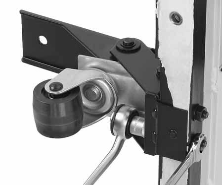
3 Model W1741/W1741S (Mfd. Since 4/14) Motor Installation Follow the instructions below before performing any steps in the Assembly section, starting on Page 14 of the W1741 Owner's Manual. To install the motor, do these steps: 1. With the help of another person, tip the stand shipping box upside down, then open the bottom of the box to expose the top of the stand. 2. Place a piece of cardboard on the floor, tip the cabinet shipping box over so that the cabinet top is on the protective cardboard, then remove the shipping box and plastic from the cabinet. 3. Reach inside the cabinet, remove the accessories box, ribbed V-belt, dust port, and place the control panel pedestal off to the side. Note: Keep the cap screws and flat washers that secure the control panel pedestal to the inside of the cabinet so they can be used to install the pedestal in a future step. 4. Use a 12mm wrench to remove the two hex nuts and flat washers that secure the motor to the cabinet top. Note: Retain the two carriage bolts, hex nuts, and flat washers so that they can be used to install the motor in Step Using cardboard to protect the stand and another person to hold the motor, place the stand on its left side so that the dust chute faces the floor. 6. Remove the rear stand panel. 7. Place the motor on the two motor mount brackets with the pulley facing the rear of the cabinet, as shown in Figure 1. Motor Mount Brackets 8. Attach the motor to the motor mount brackets with (4) M x 25 carriage bolts, 8mm flat washers, and M hex nuts (two sets from inventory and two sets that were removed in Step 4), as shown in Figure Refer to Page 14 of the Owner's Manual and follow the assembly instructions, starting at Step 2. x 4 Figure 1. Motor attached to the motor mounts. -2-
4 Model W1741/W1741S (Mfd. Since 4/14) SAFETY For Your Own Safety, Read Manual Before Operating Machine The purpose of safety symbols is to attract your attention to possible hazardous conditions. This manual uses a series of symbols and signal words intended to convey the level of importance of the safety messages. The progression of symbols is described below. Remember that safety messages by themselves do not eliminate danger and are not a substitute for proper accident prevention measures this responsibility is ultimately up to the operator! Indicates an imminently hazardous situation which, if not avoided, WILL result in death or serious injury. Indicates a potentially hazardous situation which, if not avoided, COULD result in death or serious injury. Indicates a potentially hazardous situation which, if not avoided, MAY result in minor or moderate injury. NOTICE This symbol is used to alert the user to useful information about proper operation of the equipment or a situation that may cause damage to the machinery. Standard Machinery Safety Instructions OWNER S MANUAL. Read and understand this owner s manual BEFORE using machine. TRAINED OPERATORS ONLY. Untrained operators have a higher risk of being hurt or killed. Only allow trained/supervised people to use this machine. When machine is not being used, disconnect power, remove switch keys, or lock-out machine to prevent unauthorized use especially around children. Make workshop kid proof! DANGEROUS ENVIRONMENTS. Do not use machinery in areas that are wet, cluttered, or have poor lighting. Operating machinery in these areas greatly increases the risk of accidents and injury. MENTAL ALERTNESS REQUIRED. Full mental alertness is required for safe operation of machinery. Never operate under the influence of drugs or alcohol, when tired, or when distracted. ELECTRICAL EQUIPMENT INJURY RISKS. You can be shocked, burned, or killed by touching live electrical components or improperly grounded machinery. To reduce this risk, only allow an electrician or qualified service personnel to do electrical installation or repair work, and always disconnect power before accessing or exposing electrical equipment. DISCONNECT POWER FIRST. Always disconnect machine from power supply BEFORE making adjustments, changing tooling, or servicing machine. This eliminates the risk of injury from unintended startup or contact with live electrical components. EYE PROTECTION. Always wear ANSI-approved safety glasses or a face shield when operating or observing machinery to reduce the risk of eye injury or blindness from flying particles. Everyday eyeglasses are not approved safety glasses. -3-
5 Model W1741/W1741S (Mfd. Since 4/14) WEARING PROPER APPAREL. Do not wear clothing, apparel, or jewelry that can become entangled in moving parts. Always tie back or cover long hair. Wear non-slip footwear to avoid accidental slips, which could cause loss of workpiece control. HAZARDOUS DUST. Dust created while using machinery may cause cancer, birth defects, or long-term respiratory damage. Be aware of dust hazards associated with each workpiece material, and always wear a NIOSH-approved respirator to reduce your risk. HEARING PROTECTION. Always wear hearing protection when operating or observing loud machinery. Extended exposure to this noise without hearing protection can cause permanent hearing loss. REMOVE ADJUSTING TOOLS. Tools left on machinery can become dangerous projectiles upon startup. Never leave chuck keys, wrenches, or any other tools on machine. Always verify removal before starting! INTENDED USAGE. Only use machine for its intended purpose never make modifications without prior approval from Woodstock International. Modifying machine or using it differently than intended will void the warranty and may result in malfunction or mechanical failure that leads to serious personal injury or death! AWKWARD POSITIONS. Keep proper footing and balance at all times when operating machine. Do not overreach! Avoid awkward hand positions that make workpiece control difficult or increase the risk of accidental injury. CHILDREN & BYSTANDERS. Keep children and bystanders at a safe distance from the work area. Stop using machine if they become a distraction. GUARDS & COVERS. Guards and covers reduce accidental contact with moving parts or flying debris make sure they are properly installed, undamaged, and working correctly. FORCING MACHINERY. Do not force machine. It will do the job safer and better at the rate for which it was designed. NEVER STAND ON MACHINE. Serious injury may occur if machine is tipped or if the cutting tool is unintentionally contacted. STABLE MACHINE. Unexpected movement during operation greatly increases risk of injury or loss of control. Before starting, verify machine is stable and mobile base (if used) is locked. USE RECOMMENDED ACCESSORIES. Consult this owner s manual or the manufacturer for recommended accessories. Using improper accessories will increase risk of serious injury. UNATTENDED OPERATION. To reduce the risk of accidental injury, turn machine OFF and ensure all moving parts completely stop before walking away. Never leave machine running while unattended. MAINTAIN WITH CARE. Follow all maintenance instructions and lubrication schedules to keep machine in good working condition. A machine that is improperly maintained could malfunction, leading to serious personal injury or death. CHECK DAMAGED PARTS. Regularly inspect machine for any condition that may affect safe operation. Immediately repair or replace damaged or mis-adjusted parts before operating machine. MAINTAIN POWER CORDS. When disconnecting cord-connected machines from power, grab and pull the plug NOT the cord. Pulling the cord may damage the wires inside, resulting in a short. Do not handle cord/plug with wet hands. Avoid cord damage by keeping it away from heated surfaces, high traffic areas, harsh chemicals, and wet/damp locations. EXPERIENCING DIFFICULTIES. If at any time you experience difficulties performing the intended operation, stop using the machine! Contact Technical Support at (360)
6 Model W1741/W1741S (Mfd. Since 4/14) Additional Safety for Jointers JOINTER INJURY RISKS. Familiarize yourself with the main injury risks associated with jointers always use common sense and good judgement to reduce your risk of injury. Main injury risks from jointers: amputation/lacerations from contact with the moving cutterhead, entanglement/crushing injuries from getting caught in moving parts, blindness or eye injury from flying wood chips, or impact injuries from workpiece kickback. KICKBACK. Know how to reduce the risk of kickback and kickback-related injuries. Kickback occurs during the operation when the workpiece is ejected from the machine at a high rate of speed. Kickback is commonly caused by poor workpiece selection, unsafe feeding techniques, or improper machine setup/maintenance. Kickback injuries typically occur as follows: (1) operator/bystanders are struck by the workpiece, resulting in impact injuries (i.e., blindness, broken bones, bruises, death); (2) operator s hands are pulled into blade, resulting in amputation or severe lacerations. GUARD REMOVAL. Except when rabbeting, never remove guards during operation or while connected to power. Always replace guard after rabbeting. You could be seriously injured if you accidentally touch the spinning cutterhead or get entangled in moving parts. Before removing sawdust, turn jointer OFF and disconnect power before clearing. Immediately replace guards. INSPECTING STOCK. To reduce the risk of kickback injuries or machine damage, thoroughly inspect and prepare the workpiece before cutting. Verify the workpiece is free of nails, staples, loose knots or other foreign material. Workpieces with minor warping should be surface planed first with the cupped side facing the infeed table. GRAIN DIRECTION. Jointing against the grain or end grain increases the required cutting force, which could produce chatter or excessive chip out, and lead to kickback. CUTTING LIMITATIONS. To reduce the risk of accidental cutterhead contact or kickback, never perform jointing, planing, or rabbeting cuts on pieces smaller than 8" long, 3 4 " wide, or 1 4 " thick. MAXIMUM CUTTING DEPTH. To reduce the risk of kickback, never cut deeper than 1 8 " per pass. PUSH BLOCKS. To reduce the risk of accidental cutterhead contact, always use push blocks when planing materials less than 3" high or wide. Never pass your hands directly over the cutterhead without a push block. WORKPIECE SUPPORT. To reduce accidental cutterhead contact and kickback, support workpiece continuously during operation. Position and guide workpiece with fence; support long or wide stock with auxiliary stands. DULL/DAMAGED KNIVES/INSERTS. Only use sharp, undamaged knives/inserts. Dull, damaged or rusted knives/inserts increase risk of kickback. OUTFEED TABLE ALIGNMENT. To reduce the risk of kickback and personal injuries, keep the outfeed table even with the knives/ inserts at top dead center (the highest point during rotation). If the outfeed table is set too low, the workpiece may rock against the cutterhead. If the table is set too high, the workpiece may hit the outfeed table and get stuck over the cutterhead. FEED WORKPIECE PROPERLY. To reduce the risk of kickback, never start jointer with workpiece touching cutterhead. Allow cutterhead to reach full speed before feeding. Never back work toward the infeed table. SECURE KNIVES/INSERTS. Loose knives or improperly set inserts can become dangerous projectiles or cause machine damage. Always verify knives/inserts are secure and properly adjusted before operation. Straight knives should never project more than 1 8 " (0.125") from cutterhead body. -5-
7 ELECTRICAL Circuit Requirements This machine must be connected to the correct size and type of power supply circuit, or fire or electrical damage may occur. Read through this section to determine if an adequate power supply circuit is available. If a correct circuit is not available, a qualified electrician MUST install one before you can connect the machine to power. A power supply circuit includes all electrical equipment between the breaker box or fuse panel in the building and the machine. The power supply circuit used for this machine must be sized to safely handle the fullload current drawn from the machine for an extended period of time. (If this machine is connected to a circuit protected by fuses, use a time delay fuse marked D.) Model W1741/W1741S (Mfd. Since 4/14) The machine must be properly set up before it is safe to operate. DO NOT connect this machine to the power source until instructed to do so later in this manual. Full-Load Current Rating The full-load current rating is the amperage a machine draws at 100% of the rated output power. On machines with multiple motors, this is the amperage drawn by the largest motor or sum of all motors and electrical devices that might operate at one time during normal operations. Full-Load Current Rating at 240V Amps Circuit Requirements This machine is prewired to operate on a 240V power supply circuit that has a verified ground and meets the following requirements: Circuit Type V, 60 Hz, Single-Phase Circuit Size Amps Plug/Receptacle... NEMA 6-20 Incorrectly wiring or grounding this machine can cause electrocution, fire, or machine damage. To reduce this risk, only an electrician or qualified service personnel should do any required electrical work on this machine. NOTICE The circuit requirements listed in this manual apply to a dedicated circuit where only one machine will be running at a time. If this machine will be connected to a shared circuit where multiple machines will be running at the same time, consult with an electrician to ensure that the circuit is properly sized for safe operation. -6-
8 Model W1741/W1741S (Mfd. Since 4/14) Grounding Requirements This machine MUST be grounded. In the event of certain types of malfunctions or breakdowns, grounding provides a path of least resistance for electric current to travel in order to reduce the risk of electric shock. Improper connection of the equipment-grounding wire will increase the risk of electric shock. The wire with green insulation (with/without yellow stripes) is the equipmentgrounding wire. If repair or replacement of the power cord or plug is necessary, do not connect the equipmentgrounding wire to a live (current carrying) terminal. Check with a qualified electrician or service personnel if you do not understand these grounding requirements, or if you are in doubt about whether the tool is properly grounded. If you ever notice that a cord or plug is damaged or worn, disconnect it from power, and immediately replace it with a new one. For 240V Connection This machine is equipped with a power cord that has an equipment-grounding wire and NEMA 6-20 grounding plug. The plug must only be inserted into a matching receptacle (see Figure 2) that is properly installed and grounded in accordance with local codes and ordinances. Extension Cords We do not recommend using an extension cord with this machine. Extension cords cause voltage drop, which may damage electrical components and shorten motor life. Voltage drop increases with longer extension cords and smaller gauge sizes (higher gauge numbers indicate smaller sizes). The machine must be properly set up before it is safe to operate. DO NOT connect this machine to the power source until instructed to do so later in this manual. Current Carrying Prongs 6-20 PLUG GROUNDED 6-20 RECEPTACLE Grounding Prong Figure 2. NEMA 6-20 plug & receptacle. No adapter should be used with the required plug. If the plug does not fit the available receptacle or the machine must be reconnected to a different type of circuit, the reconnection must be made by an electrician or qualified service personnel and it must comply with all local codes and ordinances. Any extension cord used with this machine must contain a ground wire, match the required plug and receptacle, and meet the following requirements: Minimum Gauge Size at 240V AWG Maximum Length (Shorter is Better)...50 ft. -7-
9 Wiring Diagram Model W1741/W1741S (Mfd. Since 4/14) Ground Hot G 240 VAC 240 VAC Hot 6-20 PLUG Bl A1 1L1 3L2 5L3 Contactor 2T1 4T2 6T3 13no A2 14no Ground CONTROL PANEL (from behind) 3 1 GND Thermal Overload Hot STOP/Reset Switch Top ON Switch Hot Ground MAGNETIC SWITCH ASSEMBLY 240V MOTOR Ground Start Capacitor 200MFD 250VAC Run Capacitor 30MFD 450VAC -8-
10 Model W1741S 8" Parallelogram Jointer with Spiral Cutterhead Manual Insert Phone #: (360) Online Tech Support: Web: The Model W1741S is the same as the Model W1741, except it has a spiral cutterhead. Besides the data sheet and parts in this insert, the content in the Model W1741 owner's manual is the same for both machines. Before operating your new machine, you MUST read and understand this insert and the entire Model W1741 manual to reduce the risk of injury from improper use or setup. If you have any further questions about this manual insert or the differences between the Model W1741S and the Model W1741, contact our Technical Support at (360) or tech-support@shopfox.biz. #10740TR COPYRIGHT MAY, 2008 BY WOODSTOCK INTERNATIONAL, INC. WARNING: NO PORTION OF THIS MANUAL MAY BE REPRODUCED IN ANY SHAPE OR FORM WITHOUT THE WRITTEN APPROVAL OF WOODSTOCK INTERNATIONAL, INC. Printed in China
11 W1741S 8" Parallelogram Jointer with Spiral Cutterhead Phone #: (360) Online Tech Support: Web: Type...TEFC Capacitor Start Induction Horsepower... 3 HP Voltage V Prewired V Phase... Single Amps... 15A Speed RPM Cycle Hz Number Of Speeds... 1 Power Transfer... V-Belt Drive Bearings... Sealed and Lubricated Cutterhead Type...Spiral with German-Made Indexable Carbide Inserts Cutterhead Diameter " Cutterhead Speed RPM Number of Cutter Spirals... 4 Number of Indexable Inserts Cutter Insert Type... Indexable Carbide with 4 Cutting Edges Cutter Dimensions x 14 x 2 MM Maximum Width of Cut... 8" Maximum Depth of Cut (per pass) " Maximum Rabbeting Depth " Bevel Jointing...Left & Right 45 Number of Cuts per Minute...21,400 Table Size "L x 8"W x 1 1 2"T Floor to Table Height " Table Adjustment Type... Lever Action Table Movement Type... Parallelogram Fence Length... 36" Fence Height... 5" Fence Thickness " Fence Stops and 90 Weight lbs. Length " Width " Height Foot Print (Length/Width) " x " -2-
12 W1741S 8" Parallelogram Jointer with Spiral Cutterhead Body...Cast Iron Cabinet...Steel Fence... Precision Ground Cast Iron Guard... Die Cast Metal Table... Precision Ground Cast Iron Paint... Powder Coated Type... Wood Crate Content...Machine Weight Lbs. Length/Width/Height... 81" x 25" x 13" Type... Cardboard Content... Stand Weight Lbs. Length/Width/Height... 38" x 18" x 28" Switch... Magnetic Switch with Thermal Overload Protection Switch Voltage...220V Cord Length... 6 ft. Cord Gauge...12 gauge Recommended Breaker Size...20 amp Included Plug...No Recommended Plug Number of Dust Ports... 1 Dust Port Size... 4" Mobile Base...Built-In Customer Assembly Time... Approximately 2 Hours Warranty... 2 Year Country of Origin... China Spiral Cutterhead with German-Made Indexable Carbide Inserts Built-In Mobile Base 3 HP Motor Easy-to-Reach Pedestal Mounted Control Panel Parallelogram Table Design Allows for Full Adjustability and Calibration 5" Tall Fence Sturdy Cabinet Stand -3-
13 W1741S 8" Parallelogram Jointer with Spiral Cutterhead Stand Breakdown -4-
14 W1741S 8" Parallelogram Jointer with Spiral Cutterhead Stand Parts List REF PART # DESCRIPTION REF PART # DESCRIPTION 1 XPW02M FLAT WASHER 5MM 30 XPLW04M LOCK WASHER 8MM 2 X PANEL 32 XPN06M HEX NUT M XPFS02M FLANGE SCREW M6-1 X XPW02M FLAT WASHER 5MM 4 X BELT GUARD 34 XPS06M PHLP HD SCR M5-.8 X 20 5 X CABINET STAND 35 X MAGNETIC SWITCH ASSY 6 XPW03M FLAT WASHER 6MM 35-1 X SWITCH BACK COVER 7 XPN01M HEX NUT M X CONTACTOR 8 XPS40M PHLP HD SCR M5-.8 X X THERMAL OVERLOAD RELAY 9 XPW02M FLAT WASHER 5MM 35-4 X SWITCH FRONT COVER 10 X DUST PORT 36 X STRAIN RELIEF 11 XPN03M HEX NUT M XPSB04M CAP SCREW M6-1 X XPW01M FLAT WASHER 8MM 38 XPW03M FLAT WASHER 6MM 13 X SLEEVE 39 X SWITCH PLATE 14 X WHEEL 42 XPR16M EXT RETAINING RING 9MM 15 XPB86M HEX BOLT M X XPW06M FLAT WASHER 12MM 16 X MOTOR BRACKET 44 X SHAFT 17 X MOTOR BRACKET NUT 45 XPB22M HEX BOLT M X X MOTOR BRACKET SCREW 46 XPW01M FLAT WASHER 8MM 19 X MOTOR CARRIAGE SCREW 47 XPN03M HEX NUT M X MOTOR CARRIAGE WASHER 48 XPN02M HEX NUT M X MOTOR CARRIAGE NUT 49 XPW04M FLAT WASHER 10MM 22 X ADJUSTING SCREW 50 XPB45M HEX BOLT M X XPN08 HEX NUT 3/ XPW01M FLAT WASHER 8MM 24 XPVA45 V-BELT A-45 4L X SPECIAL BOLT 25 X MOTOR PULLEY 53 XPR21M INT RETAINING RING 35MM 26 XPSS02M SET SCREW M6-1 X 6 54 XP6202 BALL BEARING 6202Z 27 XPK12M KEY 5 X 5 X X TROLLEY WHEEL 28 X HP MOTOR 56 X SLEEVE 28-1 X MOTOR FAN COVER 57 X TROLLEY BRACKET 28-2 X MOTOR FAN 58 XPW04M FLAT WASHER 10MM 28-3 X CAPACITOR COVER 59 XPN02M HEX NUT M XPC300S S CAPACITOR 300M 125V 60 XPB144M HEX BOLT M X X CAPACITOR COVER 61 X PEDAL BRACKET 28-6 X R CAPACITOR 40M 250V 62 X PEDAL 28-7 X JUNCTION BOX 63 XPS40M PHLP HD SCR M5-.8 X XPSB31M CAP SCREW M X 25-5-
15 -6- W1741S 8" Parallelogram Jointer with Spiral Cutterhead Jointer Breakdown
16 W1741S 8" Parallelogram Jointer with Spiral Cutterhead Jointer Parts List REF PART # DESCRIPTION REF PART # DESCRIPTION 101 X KNOB M XPSB148M CAP SCREW M X X STUD 157 XPLW04M LOCK WASHER 8MM 103 X BUSHING 158 X BEARING BLOCK LH 104 X ECCENTRIC SHAFT 159 XP60042RS BALL BEARING RS 105 XPSS11M SET SCREW M6-1 X X1741S162 SPIRAL CUTTERHEAD 106 XPSS14M SET SCREW M X XPK74M KEY 6 X 6 X X FENCE CARRIAGE 164 X1741S164 INDEXABLE INSERT 14 X 14 X XPN01M HEX NUT M X1741S166 FLAT HD TORX SCR T20 M6-1 X XPB10M HEX BOLT M6-1 X XPR25M INT RETAINING RING 47MM 112 X COLLAR 168 XP60052RS BALL BEARING RS 113 X SUPPORT 169 X BEARING BLOCK RH 114 XPW06M FLAT WASHER 12MM 170 X CUTTERHEAD PULLEY 115 XPN09M HEX NUT M XPW01M FLAT WASHER 8MM 116 XPSB72M CAP SCREW M X XPSB31M CAP SCREW M X XPW04M FLAT WASHER 10MM 173 XPSB148M CAP SCREW M X XPSB24M CAP SCREW M5-.8 X X GUARD CLAMP 119 X GIB 175 X CUTTERHEAD GUARD 120 X ECCENTRIC STUD 176 X GUARD WARNING LABEL 121 XPW01M FLAT WASHER 8MM 177 X TORSION SPRING 122 XPN03M HEX NUT M XPRP02M ROLL PIN 3 X X SHAFT 179 X SUPPORT 124 XPSB13M CAP SCREW M X X TABLE LIP 125 XPW03M FLAT WASHER 6MM 181 XPW03M FLAT WASHER 6MM 126 X POINTER 182 XPSB02M CAP SCREW M6-1 X XPW03M FLAT WASHER 6MM 183 X OUTFEED TABLE 128 XPS11M BUTTON HD CAP SCREW M6-1 X X SPRING PIN 129 X LOCK LEVER M X X BUMPER 130 X INDEX PIN ASSEMBLY 186 XPLW03M LOCK WASHER 6MM 131 XPRP42M ROLL PIN 3 X XPSB06M CAP SCREW M6-1 X X COMPRESSION SPRING 188 X BASE 133 XPB10M HEX BOLT M6-1 X X RIVET 134 XPN01M HEX NUT M X SCALE 135 X SWIVEL 191 X SHORT ADJUSTING SCREW 136 X COLLAR 192 XPN02M HEX NUT M XPSS14M SET SCREW M X XPSS01M SET SCREW M6-1 X X LOCK 194 XPSS01M SET SCREW M6-1 X XPSS14M SET SCREW M X X LONG ADJUSTING SCREW 140 X CLAMP 196 X EXTENSION SPRING 141 X THREAD CLAMP 197 X SPRING PIN 142 X TILT SCALE 198 X CHIP BREAKER 143 XPS68M PHLP HD SCR M6-1 X XPW03M FLAT WASHER 6MM 144 XPW03M FLAT WASHER 6MM 200 XPB02M HEX BOLT M6-1 X X BALL KNOB M XPW01M FLAT WASHER 8MM 146 X STUD 202 X TABLE LOCK LEVER M X X FENCE 203 X ECCENTRIC BUSHING 148 X SCALE 204 X TABLE SHAFT 149 X RIVET 205 XPSS06M SET SCREW M X X INFEED TABLE 206 X TABLE SHAFT 151 X TABLE SHAFT 207 X POINTER 152 X TABLE EXTENSION 208 XPRP44M ROLL PIN 3 X XPSB02M CAP SCREW M6-1 X XPFH19M FLAT HD SCR M4-.7 X X CHIP DEFLECTOR 210 X PIVOT BRACKET 155 XPSB26M CAP SCREW M6-1 X 12-7-
17 W1741S 8" Parallelogram Jointer with Spiral Cutterhead Jointer Parts List, cont. REF PART # DESCRIPTION REF PART # DESCRIPTION 211 X ADJUSTING BLOCK 225 XPAW08M HEX KEY 8MM 212 XPN09M HEX NUT M X1741S227 DRIVER BIT TORX T X LEVER 228 X1741S228 L-WRENCH TORX T X HANDLE KNOB M X CONTROL BOX 215 XPSB12M CAP SCREW M X X START BUTTON 216 X CLAMP PLATE 231 X STOP BUTTON 217 X MEDIUM ADJUSTING SCREW 232 X CONTROL PANEL FACE 218 X PUSH BLOCK 233 XPHTEK4M TAP SCREW M4 X XPWR810 OPEN END WRENCH 8-10MM 234 X SWITCH PEDESTAL ARM 220 XPWR1214 OPEN END WRENCH 12-14MM 235 XPFS14M FLANGE SCREW M6-1 X XPAW02.5M HEX KEY 2.5MM 236 XPSB64M CAP SCREW M X XPAW04M HEX KEY 4MM 237 XPLW06M LOCK WASHER 10MM 223 XPAW05M HEX KEY 5MM 238 XPW04M FLAT WASHER 10MM 224 XPAW06M HEX KEY 6MM 239 X BALL STRAIN RELIEF Label/Cosmetic Parts REF PART # DESCRIPTION REF PART # DESCRIPTION 301 X FENCE/CUTTERHEAD LABEL 309 X ONE LINE STRIPING 302 X CUTTERHEAD GUARD LABEL 310 X TWO LINE STRIPING 303 XLABEL-04 ELECTRICITY LABEL 311 X UNPLUG 220V POWER LABEL 304 X CONTROL PANEL FACE 312 X1741S312 MACHINE ID LABEL 305 XLABEL-11 SAFETY GLASSES LABEL 313 X1741S313 W1741S MODEL # LABEL 306 XLABEL-15 HEARING PROTECTION LABEL 314 X BLACK TOUCH UP PAINT 307 X READ MANUAL LABEL 315 X SF WHITE TOUCH UP PAINT 308 XPLOGO1 SHOP FOX LOGO PLATE -8-
 734-3482 or by email at tech_support@shopfox.biz.")

18 Model W1741 LIGHTED CONTROLS MANUAL UPDATE Improvements to this machine were made since the manual was originally printed, and this update covers those changes. Keep this update with your owner's manual in case you ever need to refer to it. If you have questions, contact Tech Support at (360) or by at Lighted Controls We added lights in the control panel buttons to indicate when there is power to the machine. The addition of these lights changes the wiring diagram and two of the electrical components pictures on Page 40 of the owner's manual. Control Panel Magnetic Switch #8283TR COPYRIGHT MAY, 2006 BY WOODSTOCK INTERNATIONAL, INC. WARNING: NO PORTION OF THIS MANUAL MAY BE REPRODUCED IN ANY SHAPE OR FORM WITHOUT THE WRITTEN APPROVAL OF WOODSTOCK INTERNATIONAL, INC. Printed in China


19 W1741 Wiring Diagram February, 2007
20 Woodstock International, Inc. P.O. Box 2309 Bellingham, WA Phone: (800) FAX: (360) Dear Valued Customer, Your new Shop Fox Model W1741 8" Jointer may or may not have switch buttons with light bulbs inside. If your machine does have these type of switch buttons, the light bulb inside is not intended to be functional with your machine and is not wired as such, or displayed in the wiring diagram in your owner's manual. The buttons with bulbs start and stop the machine as intended, and they will not hinder the performance of your machine in any way. Sincerely, The Woodstock International Quality Control Team Woodstock International, Inc. P.O. Box 2309 Bellingham, WA Phone: (800) FAX: (360) Dear Valued Customer, Your new Shop Fox Model W1741 8" Jointer may or may not have switch buttons with light bulbs inside. If your machine does have these type of switch buttons, the light bulb inside is not intended to be functional with your machine and is not wired as such, or displayed in the wiring diagram in your owner's manual. The buttons with bulbs start and stop the machine as intended, and they will not hinder the performance of your machine in any way. Sincerely, The Woodstock International Quality Control Team


21 Model W1741 8" Jointer Manual Update Why the Update? The motor is now securely bolted to the inside of the stand for shipping purposes. This update covers the setup needed to install the motor in the stand. Use these instructions first, then proceed with the setup as described in the owner's manual. Motor Installation Before mounting the jointer on the stand, the motor must be removed from its shipping position (Figure 1) and installed on the motor mounts (Figure 2). To install the motor, do these steps: 1. Turn the stand upside down and unbolt the motor from the stand. Figure 1. Motor as shipped. 2. Use the fasteners that attach the motor to the stand to attach it to the motor mounts, as shown in Figure 2. Figure 2. Motor attached to the motor mounts. #8165TR COPYRIGHT APRIL, 2006 BY WOODSTOCK INTERNATIONAL, INC. WARNING: NO PORTION OF THIS MANUAL MAY BE REPRODUCED IN ANY SHAPE OR FORM WITHOUT THE WRITTEN APPROVAL OF WOODSTOCK INTERNATIONAL, INC. Printed in China

22
23
24
25
26
27

28
29
30
31


32

33
34


35
36


37

38


39


40
41
42
43


44
45
46

47

48

49
50
51
52
53

54
55
56

57
58


59


60
61

62


63
64
65
66
67
68
69
70
71
72
73
74
75
76
77
Model W1742S 15" Planer with Spiral Cutterhead Manual Insert
 Model W1742S 15" Planer with Spiral Cutterhead Manual Insert Phone #: (360) 734-3482 Online Tech Support: tech-support@shopfox.biz Web: www.shopfox.biz The Model W1742S is the same as the Model W1742,
BUY PARTS ONLINE AT GRIZZLY.COM!
 SECTION 9: PARTS Tables, Fence & Cutterhead 28 29 26 27 25 23 23 22 24 22 35 37 36 38 16 15 17 18 39 11 14 19 20 21 13 12 6 7 8 9 10 1 2 5 49 3 4 3 31 30 6 7 94 93 95 40 96 43 42 44 45 46 47 48 55 55-4
SECTION 9: PARTS Table
 SECTION 9: PARTS Table 26 27 25 24 23 28 33 31 22 30 21 29 34 32 20 35 19 36 18 15 16 17 37 35 36 39 30 13 8 14 11 12 38 10 40 34 29 9 54 53 56 52 41 51 42 50 43 49 17 3 46 48 44 2 7 4 6 5 46 45 47 4 1
READ THIS FIRST. Phone #: (360) Tech Support: Web:
 Tech Support: Web:") READ THIS FIRST Model W1742/W1742S ***IMPORTANT UPDATE*** Applies to Models Mfd. Since 09/17 and Owner's Manuals Printed 01/06 Phone #: (360) 734-3482 Tech Support: techsupport@woodstockint.com Web: www.woodstockint.com
READ THIS FIRST Model W1742/W1742S ***IMPORTANT UPDATE*** Applies to Models Mfd. Since 09/17 and Owner's Manuals Printed 01/06 Phone #: (360) 734-3482 Tech Support: techsupport@woodstockint.com Web: www.woodstockint.com
SECTION 9: PARTS Fence & Cutterhead
 (G0855 Only) (G0856 Only) SECTION 9: PARTS Fence & Cutterhead 1 2 3 4 65 6 5 23 111 111 7 27 130 131 132 133 136 134 135 117 12 40 8 9 13 10 9 14 15 8 11 18 25 29 63 19 20 21 17 22 28 26 26 24 40-3 40-2
PARTS. Base Cabinet & Motor PARTS. Model W1745W (For Machines Mfd. Since 9/16) V2 22V2-3 22V2-4 22V2-1 22V2-2
 V2 22V2-3 22V2-4 22V2-1 22V2-2") Model W1745W (For Machines Mfd. Since 9/16) Base Cabinet & Motor 22V2-1 22V2-2 22V2-5 22V2-9 22V2-8 22V2-7 22V2-6 22V2-3 22V2-4 22V2 23 24 26 25 46 47 48 49 44 45 15 14 16 17 50 18 13 12 11 7 20 9 8 9
Model W1745W (For Machines Mfd. Since 9/16) Base Cabinet & Motor 22V2-1 22V2-2 22V2-5 22V2-9 22V2-8 22V2-7 22V2-6 22V2-3 22V2-4 22V2 23 24 26 25 46 47 48 49 44 45 15 14 16 17 50 18 13 12 11 7 20 9 8 9
PARTS Stand Breakdown
 PARTS Stand Breakdown 35-5 35-2 35-4 63 1 2 3 4 5 35-1 35-3 36 37 38 39 35 34 33 32 30 28 6 7 8 21 29 23 22 27 26 25 24 42 43 44 45 46 47 9 10 62 61 60 51 11 59 19 18 12 12 13 58 14 57 15 56 55 54 53 52
ST1007/ST1012 PARTS ST1007
 ST1007/ST1012 PARTS ST1007 Main Breakdown 30-7 30-8 30-10 30-9 30-1 30-3 30-6 30-2 30-4 30-5 82 83 84 77 78 79 80 30 60 59 58 62 64 61 46 44 63 66 65 55 56 26 45 27 45 27 25 43 37 41 50 42 72 73 51 53
MODEL W " Jointer PARTS LIST
 MODEL W1684 8" Jointer PARTS LIST Phone: 1-360-734-3482 On-Line Technical Support: tech-support@woodstockint.com COPYRIGHT SEPTEMBER, 2002 BY WOODSTOCK INTERNATIONAL, INC. WARNING: NO PORTION OF THIS MANUAL
SECTION 9: PARTS Jointer Breakdown
 Model G0490/G0490X (Mfd. Since 8/12) -49-1 3 8 7 9 12 14 15 16 18 21 23 24 24 28 29 32 33 37 38 38 44 45 49 50 51 53 55 56 57 58 59 61 60 64 65 66 68 72 75 80 81 82 83 84 85 86 87 88 90 91 92 94 93 96
MODELS W1723 and W " PLANERS PARTS LIST
 MODELS W1723 and W1724 15" PLANERS PARTS LIST Phone: 1-360-734-3482 On-Line Technical Support: tech-support@shopfox.biz COPYRIGHT DECEMBER, 2003 BY WOODSTOCK INTERNATIONAL, INC. WARNING: NO PORTION OF
MODEL W " PLANER PARTS LIST. Phone: On-Line Technical Support:
 MODEL W1692 15" PLANER PARTS LIST Phone: 1-360-734-3482 On-Line Technical Support: tech-support@shopfox.biz COPYRIGHT AUGUST, 2003 BY WOODSTOCK INTERNATIONAL, INC. WARNING: NO PORTION OF THIS MANUAL MAY
Model W1837 (For Machines Mfd. Since 8/18) PARTS. Main PARTS -83-
 PARTS. Main PARTS -83-") -83- Main 29 30 31 34 35 36 37 38 39 40 41 42 43 44 45 46 47 48 49 50 51 52 53 54 55 56 57 58 61 62 63 64 65 66 67 68 69 70 71 72 73 74 75 113 96 90 91 92 93 95 96 97 98 100 101 102 103 104 105 106 109
-83- Main 29 30 31 34 35 36 37 38 39 40 41 42 43 44 45 46 47 48 49 50 51 52 53 54 55 56 57 58 61 62 63 64 65 66 67 68 69 70 71 72 73 74 75 113 96 90 91 92 93 95 96 97 98 100 101 102 103 104 105 106 109
READ THIS FIRST. The following changes were recently made to these machines since the owner's manual was printed:
 READ THIS FIRST Model G0609/G0609X ***IMPORTANT UPDATE*** For Machines Mfg. Since August, 2012 and Owner's Manual Revised February, 2008 The following changes were recently made to these machines since
Model W1854 (For Machines Mfd. Since 02/18) PARTS. Main Breakdown 42-1 PARTS -46-
 PARTS. Main Breakdown 42-1 PARTS -46-") 3 144 1 143 119 1 4-1 14 140 13 4 1 1 4 14 11 7 108 134 131 13 14 100 1 8 16 9 80 93 40 14 146 39 Main Breakdown 133 117 130 10 3 19 3 11 10 9 38 9 7 6 4 13 7 134 16 138 141 Model W184 (For Machines Mfd.
3 144 1 143 119 1 4-1 14 140 13 4 1 1 4 14 11 7 108 134 131 13 14 100 1 8 16 9 80 93 40 14 146 39 Main Breakdown 133 117 130 10 3 19 3 11 10 9 38 9 7 6 4 13 7 134 16 138 141 Model W184 (For Machines Mfd.
MODEL G0604X 6" EXTREME SERIES PARALLELOGRAM JOINTER MANUAL INSERT
 MODEL G0604X 6" EXTREME SERIES PARALLELOGRAM JOINTER MANUAL INSERT The Model G0604X is the same as the Model G0604, except it has a 1 1 2 HP 110/220V motor. Besides the data sheet, parts, and wiring diagram
Model W1729 ***IMPORTANT UPDATE*** Applies to Models Mfg. Since 01/12 and Owner's Manual Revised Nov., 2004
 Model W1729 ***IMPORTANT UPDATE*** Applies to Models Mfg. Since 01/12 and Owner's Manual Revised Nov., 2004 Phone #: (360) 734-3482 Tech Support: tech-support@shopfox.biz Web: www.shopfox.biz We recently
SECTION 9: PARTS. G7947 Stand & Table Breakdown 4V2
 SECTION 9: PARTS G7947 Stand & Table Breakdown 19 15 21 18 16 17 112 5 113 3 14 8 7 6 6-1 13 4V2 12 116 11 9 10 2 114 115 1 We do our best to stock replacement parts when possible, but we cannot guarantee
PARTS. W1669 & W1670 Parts PARTS. Model W1669/W1670 (For Machines Mfd. Since 04/18) 66V A A A 28A
 66V A A A 28A") W1669 & W1670 Parts 23 66V2 22 21 25 26 53A 62 63 89 64 9 65 24 20 15 16A 54 93 10 16A-1 81 77 94 53 79 102 103 28 36 8 30 19 31 32 32-1 109 28A 28 27 34 33 56 49 76 76 19-3 19-1 19-2 38-1 89 35 60 59
W1669 & W1670 Parts 23 66V2 22 21 25 26 53A 62 63 89 64 9 65 24 20 15 16A 54 93 10 16A-1 81 77 94 53 79 102 103 28 36 8 30 19 31 32 32-1 109 28A 28 27 34 33 56 49 76 76 19-3 19-1 19-2 38-1 89 35 60 59
READ THIS FIRST. The following changes were recently made to these machines since the owner's manual was printed:
 READ THIS FIRST Model G0656/P/PX/X ***IMPORTANT UPDATE*** For Machines Mfg. Since April, 2014 & Owner's Manual Printed September, 2009 The following changes were recently made to these machines since the
Main Breakdown. ST " Bandsaw -41-
 Main Breakdown ST1000 14" Bandsaw -41- Main Breakdown Parts List REF PART # DESCRIPTION REF PART # DESCRIPTION 1 XST1000001 MOTOR 3/4HP 110/220V 48 XPHTEK4M TAP SCREW M4 X 8 1-1 XST1000001-1 FAN COVER
SECTION 10: PARTS. Main Model G0771Z (Mfd. Since 09/16)
") SECTION 10: PARTS Main 96 103 105 119 104 120 102 101 124 29-1 29-4 29-2 29-5 29-3 29-6 29-7 29-8 29-9 29-10 97 98 99 121 100 106 97 98 99 100 121 96 29 27 28 125 24 25 26 30 53 41 40 39 31 34 114 115
SECTION 10: PARTS Main 96 103 105 119 104 120 102 101 124 29-1 29-4 29-2 29-5 29-3 29-6 29-7 29-8 29-9 29-10 97 98 99 121 100 106 97 98 99 100 121 96 29 27 28 125 24 25 26 30 53 41 40 39 31 34 114 115
SECTION 9: PARTS. Main Breakdown -43- Model G0458Z (Mfd. Since 12/17)
") SECTION 9: PARTS Please Note: We do our best to stock replacement parts whenever possible, but we cannot guarantee that all parts shown here are available for purchase. Call (800) 53-4777 or visit our
SECTION 9: PARTS Please Note: We do our best to stock replacement parts whenever possible, but we cannot guarantee that all parts shown here are available for purchase. Call (800) 53-4777 or visit our
SECTION 10: PARTS G1023RL
 SECTION 10: PARTS 131 132 133 G1023RL (All) Main 121 118 119 128 126 125 124 123 124 122 120 119 128 116 6V2 5 4V2 4-1 129 127 128 117 26V3 26-3V2 26-1 6-2 (G1023RLWX) 26-2 26-4V3 7 6-1 1 (G1023RL) 19-1
Jointer Quick Start Guide
 Jointer Quick Start Guide This jointer runs on 220V (208V really because, 3 phase power). Don t joint anything that might have metal in it, like nails or screws. Any metal that hits the blades ruins them.
SECTION 9: PARTS Main
 63 58 62 61A 66 65 67 66 67 58 58 59 64 SECTION 9: PARTS 162 161 Main 160 45 152 21 20 17 153 166 33 30A 31 32 135 144 133 136 34 35-2 35-3 131 16 130 134 139 15 35-1 137 14V2 151 140 38 143 150 18 142
PARTS. Model W1701W (For Machines Mfd. Since 1/16) -47- REF PART # DESCRIPTION REF PART # DESCRIPTION
 -47- REF PART # DESCRIPTION REF PART # DESCRIPTION") Base Breakdown 29 25 2 3 31 8 9 32 28 27 26 23 22 19 18 17 33 36 21 1 6 3 35 37 38 390 33 3 16 3-3-2 15 3-3 3-1 3-6 3-5 12 3-7 1 11 5 7 2 7 10 9 3 6 6 2 1 2 3 5-6- Base Parts List 1 X1701W001 STAND SIDE
Base Breakdown 29 25 2 3 31 8 9 32 28 27 26 23 22 19 18 17 33 36 21 1 6 3 35 37 38 390 33 3 16 3-3-2 15 3-3 3-1 3-6 3-5 12 3-7 1 11 5 7 2 7 10 9 3 6 6 2 1 2 3 5-6- Base Parts List 1 X1701W001 STAND SIDE
G0513X2 Main. G0513 Series Bandsaws (Mfd. Since 07/18) A V2
 A V2") G0513X2 Main 55 17 48 7 16 55A 14 15 49 13 47 50 12 10 71 70 72 73 59 69 74 46 11 9 8 76 5 75 4 68 81 80 67 66 48 50 39 78 79 23 17-3 17-2 17-1 17-4 17-2 21 22 24 17-5 32 33 34 35 28 2 45 3 38 44 39 43
G0513X2 Main 55 17 48 7 16 55A 14 15 49 13 47 50 12 10 71 70 72 73 59 69 74 46 11 9 8 76 5 75 4 68 81 80 67 66 48 50 39 78 79 23 17-3 17-2 17-1 17-4 17-2 21 22 24 17-5 32 33 34 35 28 2 45 3 38 44 39 43
ST1014 PARTS ST1014 Headstock Breakdown
 ST1014 PARTS ST1014 Headstock Breakdown 112 114 23 104 105 108 102 106 20 19 21 22 101 100 103 111 38 14 15 37 46 44 47 45 107 93 39 41 40 67 110 109 74 75 76 11 12 13 9 8 6 10 31-2 31-3 3 2 7 26 24 31-1
SECTION 9: PARTS. Table. Spiral Cutterhead For Model G0452Z Cutterhead For Models G0452/P Model G0452/P/Z (Mfg.
 SECTION 9: PARTS Table 17 18 19 87 86 21 262-3 262-1 262-2 27 28 29 30 22 23 24 35 36 37 38 262 25 26 2 13 Cutterhead For Models G0452/P 10 45 12 13 7 8 9 50A 6 11 31 14 15 16 12 13 81 82 83 84 32 85 33
W /2" Dovetail Machine PARTS. Table PARTS -36-
 Table -36- Table Parts List 101 X1805101 FENCE 117 X1805117 INDICATOR TEMPLATE 1" & 2" 102 X1805102 SLIDING ROD 118 X1805118 INDICATOR TEMPLATE 1-1/2" & 2-1/2" 103 XPSB31M CAP SCREW M8-1.25 X 25 119 XPSB04M
G0604 6" X 56" Jointer -43- Jointer Parts Breakdown
 G0604 6" X 56" Jointer -43- Jointer Parts Breakdown Jointer Parts List 1 P0604001 HANDLE 43 PS68M PHLP HD SCR M6-1 X 10 2 P0604002 STUD 44 PW03M FLAT WASHER 6MM 3 P0604003 BUSHING 45 P0604045 BALL HANDLE
Lower Cabinet and Sanding Motor
 Lower Cabinet and Sanding Motor -40- Parts List 1 X1751001 MACHINE BASE 38 X1751038 BRAKE PIN 2 X1751002 QUILL BASE 39 XPR47M EXT RETAINING RING 13MM 3 XPB32M HEX BOLT M10-1.5 X 25 40 XPLW06M LOCK WASHER
SECTION 9: PARTS G7945/G7946
 SECTION 9: PARTS G7945/G7946 Main Parts 22 53 25 26 31 139 32 32-1 60 38 59 38-1 119 35 37 31 38-3 124 125 45A-2 45A-4 45A-1 31 60 45A-3V2 120 121 62 28 28-1 28 27 34 50 51 39 41 126 137 36 46 40 63 33
W1812 Owner's Manual (Mfd. Since 02/11) PARTS. Headstock 11V2 30V2 95V V2 8 25V2 41V2 25V2 23V2 27V2 PARTS -45-
 PARTS. Headstock 11V2 30V2 95V V2 8 25V2 41V2 25V2 23V2 27V2 PARTS -45-") -45- Headstock 20 21 23V2 8 25V2 23V2 25V2 26 28 87 88 57 56 40 47 39 39 37 46 33 34 42 63 13 2 93 93 71 70 69 17 41V2 92 30V2 31 32 7 38 35 33 34 37 40 43 16 11V2 1 4 5 9 61 62 61 62 18 10 3 8 19 14 95V2
-45- Headstock 20 21 23V2 8 25V2 23V2 25V2 26 28 87 88 57 56 40 47 39 39 37 46 33 34 42 63 13 2 93 93 71 70 69 17 41V2 92 30V2 31 32 7 38 35 33 34 37 40 43 16 11V2 1 4 5 9 61 62 61 62 18 10 3 8 19 14 95V2
SECTION 9: PARTS. Table Breakdown REF PART # DESCRIPTION REF PART # DESCRIPTION
 SECTION 9: PARTS Table Breakdown 1 2 3 4 5 6 7 8 9 10 11 12 13 14 15 16 17 18 19 20 21 22 23 24 23 25 17 26 27 8 1 P0675001 CAP SCREW M8-1.25 X 30 15 P0675015 SUPPORT BLOCK 2 P0675002 TABLE SUPPORT BLOCK
MODEL H8178 POWER FEED OWNER'S MANUAL
 MODEL H8178 POWER FEED OWNER'S MANUAL WARNING: NO PORTION OF THIS MANUAL MAY BE REPRODUCED IN ANY SHAPE OR FORM WITHOUT THE WRITTEN APPROVAL OF GRIZZLY INDUSTRIAL, INC. This manual provides critical safety
Model W1755S 6" Parallelogram Jointer with Spiral Cutterhead Manual Insert
 Model W1755S 6" Parallelogram Jointer with Spiral Cutterhead Manual Insert Phone #: (360) 734-3482 Online Tech Support: tech-support@shopfox.biz Web: www.shopfox.biz The Model W1755S is the same as the
Model W1739 Variable Speed Planer Moulder Manual Insert
 Model W1739 Variable Speed Planer Moulder Manual Insert READ and understand this W1739 manual insert and the W1693 instruction manual before using this machine. Ignoring this warning may lead to serious
READ THIS FIRST. For questions or help with this product contact Tech Support at (570) or
 or") READ THIS FIRST Models G0453, G0453Z, G0454, G0454Z ***IMPORTANT UPDATE*** For Machines Mfd. Since 09/17 and Owner's Manuals Revised 11/12 For questions or help with this product contact Tech Support at
READ THIS FIRST Models G0453, G0453Z, G0454, G0454Z ***IMPORTANT UPDATE*** For Machines Mfd. Since 09/17 and Owner's Manuals Revised 11/12 For questions or help with this product contact Tech Support at
D('00 D]^ ('&'. G8IKJ
![D('00 D]^ ('&'. G8IKJ](/thumbs/90/103707123.jpg "D('00 D]^ ('&'. G8IKJ") 1 2 5 6 7 8 11 12 10 13 14 15 27 28 16 26 29 30 25 17 19 20 22 21 32 23 24 31 42 43 33 34 40 41 35 49 36 37 51 52 53 44 45 46 47 38 39 48 18-40- 1 XM1099001 CONTROL PANEL FACE 29 XPCAP50M CAP SCREW M5-.8
1 2 5 6 7 8 11 12 10 13 14 15 27 28 16 26 29 30 25 17 19 20 22 21 32 23 24 31 42 43 33 34 40 41 35 49 36 37 51 52 53 44 45 46 47 38 39 48 18-40- 1 XM1099001 CONTROL PANEL FACE 29 XPCAP50M CAP SCREW M5-.8
M1110 Mill with Dovetail Column. Headstock PARTS -33-
 -33- M1110 Mill with Dovetail Column 1012 1082 1083 1001 1084 1002 1003 1005 1006 1007 1008 1009 1010 1011 1097 1096 1095 1019 1017 1094 1073 1015 1081 1016 1013 1014 1018 1020 1021 1022 1023 1024 1025
SECTION 9: PARTS. Headstock
 SECTION 9: PARTS We do our best to stock replacement parts when possible, but we cannot guarantee that all parts shown are available for purchase. Call (800) 52-4777 or visit www.grizzly.com/parts to check
SECTION 9: PARTS Table
 SECTION 9: PARTS Table 33 We do our best to stock replacement parts when possible, but we cannot guarantee that all parts shown are available for purchase. Call (800) 523-4777 or visit www.grizzly.com/
SECTION 9: PARTS G0453Z
 parts breakdown SECTION 9: PARTS G0453Z Headstock Breakdown 4 3 2 20 26 104 21 19 23 22 24 99 97 98 25 94 95 93 14 15 39 40 107 86 41 42 45 62 30 66 61 60 13 9 10 12 11 27 31 33 34 35 73 77-1 77 36 3738
15" PLANER MODEL G1021Z PARTS LIST
 15" PLANER MODEL G1021Z PARTS LIST COPYRIGHT 2000 BY GRIZZLY INDUSTRIAL, INC. WARNING: NO PORTION OF THIS MANUAL MAY BE REPRODUCED IN ANY SHAPE OR FORM WITHOUT THE WRITTEN APPROVAL OF GRIZZLY INDUSTRIAL,
MODEL W " WIDE BELT SANDER PARTS LIST. Phone: On-Line Technical Support:
 MODEL W1710 24" WIDE BELT SANDER PARTS LIST Phone: 1-360-734-3482 On-Line Technical Support: tech-support@shopfox.biz COPYRIGHT SEPTEMBER, 2003 BY WOODSTOCK INTERNATIONAL, INC. WARNING: NO PORTION OF THIS
INSTRUCTION MANUAL 6 & 8 JOINTERS WITH SPIRAL CUTTERHEAD. MODEL: KC-75FX (6 Jointer) MODEL: KC-85FX (8 Jointer)
 MODEL: KC-85FX (8 Jointer)") 6 & 8 JOINTERS WITH SPIRAL CUTTERHEAD MODEL: KC-75FX (6 Jointer) MODEL: KC-85FX (8 Jointer) INSTRUCTION MANUAL COPYRIGHT 2007 ALL RIGHTS RESERVED BY KING CANADA TOOLS INC. WARRANTY INFORMATION 2-YEAR LIMITED
6 & 8 JOINTERS WITH SPIRAL CUTTERHEAD MODEL: KC-75FX (6 Jointer) MODEL: KC-85FX (8 Jointer) INSTRUCTION MANUAL COPYRIGHT 2007 ALL RIGHTS RESERVED BY KING CANADA TOOLS INC. WARRANTY INFORMATION 2-YEAR LIMITED
OPERATORS MANUAL. JOINTER by INVICTA. Model DI-42. (877) East (800) West
 East (800) West") OPERATORS MANUAL JOINTER by INVICTA Model DI-42 INVICTA USA (877) 308-6423 - East (800) 499-4682 - West English Version Model DI-42 General Instructions As with all equipment, safety is to be a priority.
OPERATORS MANUAL JOINTER by INVICTA Model DI-42 INVICTA USA (877) 308-6423 - East (800) 499-4682 - West English Version Model DI-42 General Instructions As with all equipment, safety is to be a priority.
SECTION 9: PARTS Main Breakdown
 SECTION 9: PARTS Main Breakdown 2 115 75 113 112 8 9 7 8 11 4 5 3 3 85 81 79 78 90 84 68 69 69 68 87 86 86 91 95 98-2 98-1 98-3 98-4 98 98-8 98-9 98-5 98-6 99 97 98-7 100 92 114 108 107 110 109 111 104
Model W1819/W1820 (Mfg. Since 09/11) PARTS. Body V V PARTS -79-
 PARTS. Body V V PARTS -79-") -79- Model W1819/W1820 (Mfg. Since 09/11) 155V2 155-1 155-2 155-3V2 155-6 155-5 108 109 109 156 110 110 168 169 170 171 101 102 103 104 105 106 107 108 109 114 115 118 119 120 121 122 123 124 125 126 127
-79- Model W1819/W1820 (Mfg. Since 09/11) 155V2 155-1 155-2 155-3V2 155-6 155-5 108 109 109 156 110 110 168 169 170 171 101 102 103 104 105 106 107 108 109 114 115 118 119 120 121 122 123 124 125 126 127
Main Parts. -6- Model G0555LA35 (Mfd. Since 10/17) 30A V
 30A V") 60 49 50 76 41 65 66 44 46 43 42 47 51 63 58 64 59 48 62 16 61V2 50 51 55 56 57 70 49 69 64 55 56 43 57 167 154 41 40 8 22 30A 44 45 3 4 Main Parts 14 15 16 7 168 155 30 195 34 194 186 6 68 24 115 116
60 49 50 76 41 65 66 44 46 43 42 47 51 63 58 64 59 48 62 16 61V2 50 51 55 56 57 70 49 69 64 55 56 43 57 167 154 41 40 8 22 30A 44 45 3 4 Main Parts 14 15 16 7 168 155 30 195 34 194 186 6 68 24 115 116
MODEL T " HELICAL CUTTERHEAD INSTALLATION INSTRUCTIONS
 MODEL T27696 12" HELICAL CUTTERHEAD INSTALLATION INSTRUCTIONS For questions or help with this product contact Tech Support at (570) 546-9663 or techsupport@grizzly.com Introduction The Model T27696 indexable
Model D4500/D4501 6" & 8" Indexable Insert Spiral Cutterheads Instruction Sheet
 Model D4500/D4501 6" & 8" Indexable Insert Spiral Cutterheads Instruction Sheet Phone #: (360) 734-3482 Online Tech Support: tech-support@shopfox.biz Web: www.shopfox.biz Introduction These indexable-insert
G5959Z 12" Left-Tilting Table Saw -37-
 Date Serial Number GROUND. 329 401 403 411 ALWAYS USE GUARDS AND ANTI-KICKBACK DEVICES 401 107 106 152 406 404 405 408 138 412 410 409 402 151 101A 139 144 143 140 142 141 114 101B 137 108 102 103 128A
MODEL G " FOOT SHEAR OWNER'S MANUAL
 MODEL G5772 52" FOOT SHEAR OWNER'S MANUAL WARNING: NO PORTION OF THIS MANUAL MAY BE REPRODUCED IN ANY SHAPE OR FORM WITHOUT THE WRITTEN APPROVAL OF GRIZZLY INDUSTRIAL, INC. Table of Contents INTRODUCTION...
SECTION 9: PARTS Main
 SECTION 9: PARTS Main 58 63 67 66 65 67 66 59 58 49 58 48 49 61A 61 64 62 55 50 35-3 34 35-1 57 56 41 42 151 51 50 33A 35-2 30A 30A-1 35 38 39 31 32 18 40 43 44 68 51 41 45 46 57 56 55 47 152 153 20 21
SECTION 10: PARTS. Body. 440V Conversion Kit
 SECTION 10: PARTS We do our best to stock replacement parts when possible, but we cannot guarantee that all parts shown are available for purchase. Call (800) 523-4777 or visit www.grizzly.com/parts to
Inventory (Figure 2)
") MODEL T10127 12" SPIRAL CUTTERHEAD INSTRUCTIONS The Model T10127 indexable insert spiral cutterhead is designed to replace the straightknife cutterhead from the Grizzly jointer Model G0609. The total procedure
MODEL T10127 12" SPIRAL CUTTERHEAD INSTRUCTIONS The Model T10127 indexable insert spiral cutterhead is designed to replace the straightknife cutterhead from the Grizzly jointer Model G0609. The total procedure
MODEL T " SPIRAL CUTTERHEAD INSTALLATION INSTRUCTIONS
 MODEL T27449 8" SPIRAL CUTTERHEAD INSTALLATION INSTRUCTIONS The Model T27449 indexable insert spiral cutterhead is designed to replace the straightknife cutterhead on the Grizzly jointer Model G0490W/G0490XW
G0513X2 Main -87- G0513 Series Bandsaws 82V V2 82-6V2 95A V2 82-5V2 82-1V2 82-4V V A
 G0513X2 Main 23 55 22 48 17 17-1 17-2 21 7 17-3 17-2 17-4 24 17-5 18-5 22 24 21 55A 50 8 9 49 11 12 13 14 15 47 16 10 46 45 3 44 43 39 38 37 39 40 32 33 36 42 34 35 2 25 28 18-4 18-2 18-3 31 30 29 18-1
MODEL NO.: MI OPERATING MANUAL
 MODEL NO.: MI-81200 OPERATING MANUAL RULES for SAFE OPERATION Before you operate this machine, take a moment to read this manual. Learn how to use this jointer safely, and understand this machine s applications,
W1756/W " Wide-Belt Sander PARTS. Electrical & Controls PARTS -57-
 Electrical & Controls -57- Electrical & Controls Parts List REF PART # DESCRIPTION REF PART # DESCRIPTION 1 X1756001 ELECTRICAL CONTROL BOX 18 XPS51M PHLP HD SCR M4-.7 X 30 2 X1756002 HINGE 19 X1756019
READ THIS FIRST. For questions or help with this product contact Tech Support at (570) or
 or") READ THIS FIRST Model G5912Z/G7214Z/G8621 ***IMPORTANT UPDATE*** For Machines Mfd. Since 1/17 and Owner's Manual Printed 2001 For questions or help with this product contact Tech Support at (570) 546-9663
READ THIS FIRST Model G5912Z/G7214Z/G8621 ***IMPORTANT UPDATE*** For Machines Mfd. Since 1/17 and Owner's Manual Printed 2001 For questions or help with this product contact Tech Support at (570) 546-9663
ET-110 EXTREMA MACHINERY COMPANY, INC. P.O. BOX 1450, ALBANY, LOUISIANA (877) FAX (225)
 FAX (225)") ET-0 EXTREMA MACHINERY COMPANY, INC. P.O. BOX 450, ALBANY, LOUISIANA 707 (877) 398-7362 FAX (225) 567-2966 PREFACE The XT-0 is precision built and manufactured to satisfy the highest standards. For maximum
ET-0 EXTREMA MACHINERY COMPANY, INC. P.O. BOX 450, ALBANY, LOUISIANA 707 (877) 398-7362 FAX (225) 567-2966 PREFACE The XT-0 is precision built and manufactured to satisfy the highest standards. For maximum
MI MI OPERATING MANUAL
 MODEL NO.: MI-76100 MI-76150 OPERATING MANUAL RULES for SAFE OPERATION MAGNUM INDUSTRIAL MI-76100 and MI 76150 DRILL PRESSES To help ensure safe operation, please take a moment to learn the how to operate
INSTRUCTION MANUAL TAPER ATTACHMENT MODEL M1022. Phone: (360) On-Line Technical Support: FOR USE WITH MODEL M1019
 On-Line Technical Support: FOR USE WITH MODEL M1019") MODEL M1022 TAPER ATTACHMENT FOR USE WITH MODEL M1019 INSTRUCTION MANUAL Phone: (360) 734-3482 On-Line Technical Support: tech-support@shopfox.biz #6809BL COPYRIGHT DECEMBER, 2004 BY WOODSTOCK INTERNATIONAL,
MODEL M1022 TAPER ATTACHMENT FOR USE WITH MODEL M1019 INSTRUCTION MANUAL Phone: (360) 734-3482 On-Line Technical Support: tech-support@shopfox.biz #6809BL COPYRIGHT DECEMBER, 2004 BY WOODSTOCK INTERNATIONAL,
MODEL H " BYRD SHELIX CUTTERHEAD INSTRUCTIONS
 MODEL H9291 12" BYRD SHELIX CUTTERHEAD INSTRUCTIONS The Model H9291 12" Byrd Shelix cutterhead is designed to replace the straight-knife cutterhead on the Grizzly jointer Model G0609. The total procedure
VARIABLE SPEED BECH LATHE
 VARIABLE SPEED BECH LATHE Instruction Manual Please read this instruction manual thoroughly and follow all directions carefully. 1 Important Safety Instructions READ ALL INSTRUCTIONS AND WATNINGS BEFORE
MODEL T27697 & T " & 8" HELICAL CUTTERHEADS INSTALLATION INSTRUCTIONS
 MODEL T27697 & T27699 6" & 8" HELICAL CUTTERHEADS INSTALLATION INSTRUCTIONS For questions or help with this product contact Tech Support at (570) 546-9663 or techsupport@grizzly.com These indexable insert
Main Breakdown. Model G0531B/G0566B V2 (G0531B) 80V2-2
 80V2-2") Main Breakdown 53 85-1 54 59 54 56 54 52 55 57 175 53 56 85 29 119-2 114 89 22 119-2 119 107 119-5 119-3 119-6 119-1 29 22 119-4 114 112 96 113 114 100 116 117 105 120 102 103 108 115 99 98 92 91 90 73
Main Breakdown 53 85-1 54 59 54 56 54 52 55 57 175 53 56 85 29 119-2 114 89 22 119-2 119 107 119-5 119-3 119-6 119-1 29 22 119-4 114 112 96 113 114 100 116 117 105 120 102 103 108 115 99 98 92 91 90 73
REF PART # DESCRIPTION REF PART # DESCRIPTION
 MODEL G0453P POLAR BEAR SERIES 15" PLANER Manual Insert Congratulations on your purchase of a Model G0453P Planer! The Model G0453P is the same machine as the Model G0453Z but with a "cool" new look and
Inventory (Figure 2)
") MODEL T10130/T10126 6" & 8" SPIRAL CUTTERHEAD INSTRUCTIONS The Model T10126/T10130 indexable insert spiral cutterheads are designed to replace straightknife cutterheads from the Grizzly jointer Models
MODEL T10130/T10126 6" & 8" SPIRAL CUTTERHEAD INSTRUCTIONS The Model T10126/T10130 indexable insert spiral cutterheads are designed to replace straightknife cutterheads from the Grizzly jointer Models
MODEL G0632Z 16" X 42" VARIABLE- SPEED WOOD LATHE MANUAL INSERT
 MODEL G0632Z 16" X 42" VARIABLE- SPEED WOOD LATHE MANUAL INSERT The Model G0632Z is the same machine as the Model G0632 except it has a higher full-load current rating, a different inverter and inverter
Electrical Parts. Replaces Page 42. Model W1737/W1738 (Mfd. Since 1/14) (W1737 Only) 2V2 3V3 3-1V2 (W V.
 (W1737 Only) 2V2 3V3 3-1V2 (W V.") Model W1737/W1738 (Mfd. Since 1/14) Replaces Page 42 Electrical Parts 7 6 8 17 15 15 35 16 10 20 26 18 23 12 38 (W1737 Only) 1 31 34 37 21 24 9 2V2 3V3 3-1V2 (W1738 440V Conversion Only) 39 25 14V2 12-1
Model W1737/W1738 (Mfd. Since 1/14) Replaces Page 42 Electrical Parts 7 6 8 17 15 15 35 16 10 20 26 18 23 12 38 (W1737 Only) 1 31 34 37 21 24 9 2V2 3V3 3-1V2 (W1738 440V Conversion Only) 39 25 14V2 12-1
HOLE CUTTER SHARPENER ASSEMBLY & SERVICE MANUAL
 HOLE CUTTER SHARPENER ASSEMBLY & SERVICE MANUAL WARNING You must thoroughly read and understand this manual before operating the equipment, paying particular attention to the Warning & Safety instructions.
READ THIS FIRST Models G0544/G5850Z/ G5851Z/G7213Z
 READ THIS FIRST Models // G5851Z/G7213Z ***IMPORTANT UPDATE*** For Machines Mfd. Since 12/16 and Owner's Manual Revised 03/06 For questions or help with this product contact Tech Support at (570) 546-9663
10" Wet Tile Cutting Saw
 8035735 10" Wet Tile Cutting Saw Owner s Manual Read and understand all instructions before operation. Keep this manual for future reference pg. 2 SPECIFICATIONS ITEM DESCRIPTION Overall Dimensions (saw
SECTION 10: PARTS Body
 -76- Model G0690/G0691 (Mfd. 6/15+) SECTION 10: PARTS 55V2 55-1 55-2 55-3V2 55-5 55-6 8 9 9 56 10 10 68 69 70 71 55-4 1 2 3 4 5 6 7 8 9 14 15 18 19 20 21 22 23 24 25 26 27 27 28 29 30 31 32 32 33 33 34
MODEL G0490/G0490X 8" X 76" JOINTER w/parallelogram BEDS
 MODEL G0490/G0490X 8" X 76" JOINTER w/parallelogram BEDS OWNER'S MANUAL (For models manufactured since 8/12) COPYRIGHT DECEMBER, 2005 BY GRIZZLY INDUSTRIAL, INC., REVISED DECEMBER, 2017 (HE) WARNING: NO
Home Workshop System WARNING. MARK V Model 500. Summary Manual. Designed and Built in Dayton, Ohio.
 Shopsmith Mark V Home Workshop System MARK V Model 500 Summary Manual Designed and Built in Dayton, Ohio. WARNING Read the SAFETY information in the Introduction section and complete the ASSEMBLY AND ALIGNMENT
C a r r i a g e A s s e m b l y R e p l a c e m e n t
 E1 TF-CR C a r r i a g e A s s e m b l y R e p l a c e m e n t October 2007 Software Version 5.0 and higher IMPORTANT! TigerStop must be enabled with a code that must be obtained from TigerStop Customer
READ THIS FIRST. For questions or help with this product contact Tech Support at (570) or
 or") READ THIS FIRST Model G0728-31 ***IMPORTANT UPDATE*** For Machines Mfd. Since 01/17 and Owner's Manual Revised 09/14 For questions or help with this product contact Tech Support at (570) 546-9663 or techsupport@grizzly.com
READ THIS FIRST Model G0728-31 ***IMPORTANT UPDATE*** For Machines Mfd. Since 01/17 and Owner's Manual Revised 09/14 For questions or help with this product contact Tech Support at (570) 546-9663 or techsupport@grizzly.com
J-3-D PART NO DATE:
 37-380 & 37-877 8 PROFESSIONAL JOINTER J-3-D PART NO. 909563 DATE: 05-12-04 Page1/ J-3-D /DEB REPLACEMENT PARTS * 1345487 CUTTERHEAD ASSY, INCL: 1 1340196 KNIFE SCREW 2 1345488 BAR 3 37-355 KNIVES (SET
Record the serial number and date of purchase on your parts list for future reference.
 Jointer Model: 0-0 Parts List Record the serial number and date of purchase on your parts list for future reference. Serial number: Date of purchase: Part # 0-0PL For more information: www.rikontools.com
MODEL W1745W 6" JOINTER W/MOBILE BASE OWNER'S MANUAL (FOR MODELS MANUFACTURED SINCE 9/16)
") MODEL W1745W 6" JOINTER W/MOBILE BASE OWNER'S MANUAL (FOR MODELS MANUFACTURED SINCE 9/16) Phone: (360) 734-3482 Online Technical Support: techsupport@woodstockint.com COPYRIGHT FEBRUARY, 2016 BY WOODSTOCK
MODEL W1745W 6" JOINTER W/MOBILE BASE OWNER'S MANUAL (FOR MODELS MANUFACTURED SINCE 9/16) Phone: (360) 734-3482 Online Technical Support: techsupport@woodstockint.com COPYRIGHT FEBRUARY, 2016 BY WOODSTOCK
ALL RIGHTS RESERVED BY KING CANADA TOOLS INC.
 INDUSTRIAL RIP FENCE SYSTEM MODELS KRF-10/30L12-30 CONTRACTOR SAWS KRF-10/52L12-52 CONTRACTOR SAWS KRF-100/T50L12-50 CABINET SAWS INSTRUCTION MANUAL COPYRIGHT C 2000 ALL RIGHTS RESERVED BY KING CANADA
The following change was recently made since the owner's manual was printed:
 READ THIS FIRST Model G0531B/G0566B/ G0568/G0569 ***IMPORTANT UPDATE*** For Machines Mfd. Since 08/04 and Owner's Manual Revised 05/15 For questions or help with this product contact Tech Support at (570)
READ THIS FIRST. Phone #: (360) Tech Support: Web:
 Tech Support: Web:") READ THIS FIRST Model W1763 ***IMPORTANT UPDATE*** Applies to Models Mfg. Since 7/12 and Owner's Manual April, 2010 Phone #: (360) 734-3482 Tech Support: tech-support@shopfox.biz Web: www.shopfox.biz The
READ THIS FIRST Model W1763 ***IMPORTANT UPDATE*** Applies to Models Mfg. Since 7/12 and Owner's Manual April, 2010 Phone #: (360) 734-3482 Tech Support: tech-support@shopfox.biz Web: www.shopfox.biz The
SECTION 9: PARTS. G9860/G9860ZX Cabinet Breakdown & Parts List
 MIN SECTION 9: PARTS G9860/G9860ZX Cabinet Breakdown & Parts List 9 33 34 5 11 237V4 236V2 10 23 32 17 12 13 16 POWER STOP 5000 15 14 17 31 27 35 30 17 26 3 1 33 34 1 P9860001 BASE 17 PS68M PHLP HD SCR
TB & SB Series Drill Presses
 TB & SB Series Drill Presses OWNERS MANUAL BENCH AND FLOOR DRILL PRESS TB-16 Series & SB-16-25-32-Series FOR YOUR OWN SAFETY AND OPTIMUM OPERATION READ INSTRUCTION MANUAL BEFORE OPERATING DRILL PRESS RETAIN
Model W1741 LIGHTED CONTROLS MANUAL UPDATE. Lighted Controls. Control Panel. Magnetic Switch
 Model W1741 LIGHTED CONTROLS MANUAL UPDATE Improvements to this machine were made since the manual was originally printed, and this update covers those changes. Keep this update with your owner's manual
MODEL T " HELICAL CUTTERHEAD INSTALLATION INSTRUCTIONS
 MODEL T27698 6" HELICAL CUTTERHEAD INSTALLATION INSTRUCTIONS For questions or help with this product contact Tech Support at (570) 546-9663 or techsupport@grizzly.com The Model T27698 indexable insert
READ THIS FIRST. For questions or help with this product contact Tech Support at (570) or
 or") READ THIS FIRST Model G0811 ***IMPORTANT UPDATE*** For Machines Mfd. Since 02/16 and Owner's Manual Printed 11/16 For questions or help with this product contact Tech Support at (570) 546-9663 or techsupport@grizzly.com
READ THIS FIRST Model G0811 ***IMPORTANT UPDATE*** For Machines Mfd. Since 02/16 and Owner's Manual Printed 11/16 For questions or help with this product contact Tech Support at (570) 546-9663 or techsupport@grizzly.com
Item# " VARIABLE SPEED BENCH GRINDER USER'S MANUAL
 Power Tools Item# 33309 3" VARIABLE SPEED BENCH GRINDER USER'S MANUAL Read carefully and understand RULES FOR SAFE OPERATION and instructions before operating. Failure to follow the safety rules and other
Model D1700/D1701 Moulding Head Instruction Sheet
 Model D1700/D1701 Moulding Head Instruction Sheet Phone #: (360) 734-3482 Online Tech Support: tech-support@shopfox.biz Web: www.shopfox.biz To reduce risk of serious personal injury when using moulding
SECTION 9: PARTS G0513/G0513P/G0513ANV
 SECTION 9: PARTS G0513/G0513P/G0513ANV Main 21 22 23 82-6 82-5 48 22 19 20 24 18 17 24 17 26 21 55 17 16 14 15 32 33 34 20 18 27 25 50 13 47 18 82-1 175 35 55A 49 9 11-1 10 46 45 11 12 44 176 39 38 37
MODEL M1023 QUICK CHANGE COLLET ATTACHMENT INSTRUCTION MANUAL. Phone: On-Line Technical Support:
 MODEL M1023 QUICK CHANGE COLLET ATTACHMENT INSTRUCTION MANUAL Phone: 1-360-734-3482 On-Line Technical Support: tech-support@shopfox.biz #6727BL COPYRIGHT JANUARY, 2005 BY WOODSTOCK INTERNATIONAL, INC.
MODEL G0821 6" BENCHTOP JOINTER w/spiral CUTTERHEAD
 MODEL G0821 6" BENCHTOP JOINTER w/spiral CUTTERHEAD OWNER'S MANUAL (For models manufactured since 03/18) 3092372 COPYRIGHT FEBRUARY, 2017 BY GRIZZLY INDUSTRIAL, INC., REVISED FEBRUARY, 2018 (HE) WARNING:
VARIABLE SPEED WOOD LATHE
 MODEL MC1100B VARIABLE SPEED WOOD LATHE INSTRUCTION MANUAL Please read and fully understand the instructions in this manual before operation. Keep this manual safe for future reference. Version: 2015.02.02