JointCAM Reference Guide. JointCAM. Reference Guide. Version 1.05 Copyright G-Force CNC, LLC, All Rights Reserved.
|
|
|
- Sarah Matthews
- 5 years ago
- Views:
Transcription
1 JointCAM Reference Guide JointCAM Reference Guide Version 1.05 Copyright G-Force CNC, LLC, All Rights Reserved. 1 of 50
2 JointCAM Reference Guide Disclaimer All CNC machines are potentially dangerous. Because G-Force CNC, LLC cannot control how the software described in this manual will be used, G-Force CNC, LLC can not be responsible for any loss or damage to workpiece, machine or individual caused by misuse of the software or CNC machine. The output from the software should be thoroughly checked before using it with a CNC machine. The information in this manual may be subject to change without notice. The software described in this manual is supplied under the terms and conditions of the End User License Agreement and may only be used in accordance with this agreement. 2 of 50
3 JointCAM Reference Guide Table of Contents Introduction...7 Requirements...8 CNC Machine Requirements...8 PC Requirements...9 Supported Operating Systems:...9 Installation...10 Updating...10 Configuration...11 G-Code Options...11 G-Code or Shopbot.sbp...11 Export Roughing Toolpaths Only...11 File Extension...11 Decimal Places...11 Use Line Numbers G-Code Only...11 Inch(G20) & mm(g21) G-Code Only...11 Use Mach3 G91.1 G-Code Only...11 Include Tool and Material Comments...11 M7 Yes/No G-Code Only...11 M8 Yes/No G-Code Only...12 Startup Codes Shopbot Enable Tool Change Commands...12 Initial Tool Change/ Spindle Start...12 G43 Length Offset Yes/No G-Code Only...12 Tool Change...13 Ending Codes M2 Yes/No (Shopbot Add END commnad)...13 M30 Yes/No G-Code Only...13 Final End Code G-Code Only...13 Go to Park Position at End of Cycle...13 Include File Name in G-Code File...13 General Settings...14 Show/Hide Tooltips...14 Disable Rabbeted Dovetail Warning Messages...14 Machine Setup...14 Clearance Plane...14 First Rapid Height...14 X Axis Origin Y Axis Origin...14 Machine Width...14 Dovetail/Box Joint Axis...14 Machine Width = Stock Width...15 Use Positive End of Machine (Rotate Origin 180 )...15 File Paths...16 Specify and Use Default G-Code folder...16 Specify and Use Default Project Folder...16 Plunge Rate Percentage...17 Scale Feedrate Yes/No...17 Scale Factor...17 Unit Conversion...17 Inches to mm's...17 mm's to Inches of 50
4 JointCAM Reference Guide Convert Feedrate...17 ShopBot Spindle Control...17 Shopbot Control Spindle with SO, #,# Commands...17 Shopbot Use Multiple Heads...17 Spindle #1 Output #...18 Spindle #1 Axis...18 Spindle #2 Output #...18 Spindle #2 Axis...18 Head #2 X Offset...18 Head #2 Y Offset...18 Dovetails...19 The Half Blind Interface(s)...20 Dovetail Parameters...20 Width of Stock...21 Thickness of Stock...21 Depth of Cut...21 Start Distance...21 Dovetail Type...21 One Pass or Multi-Pass...21 Tail Width...21 Pin Width...21 Pins = Tails...21 Full Tails Only...22 # of Tails...22 Pin/Tail Offset =...22 Scoring Pass...22 Scoring Depth...23 Clearance...23 Use Roughing Tool...23 Roughing Allowance...23 Roughing Depth Allowance...24 Roughing Stepover %...24 Tail Socket Overcut...24 Calculate / Preview...25 Tail/Pin Data (Half Blind Custom only)...25 #1 Tail Width through #11 Tail Width...25 #1 Pin Width through #10 Pin Width...25 Use Minimum Pin Width...25 Symmetrical...25 Center Last Tail...25 Center Pin Width (read only)...25 Clear All...25 Tool Parameters...27 Tool #...27 Diameter...27 Length...27 Angle (Dovetail tools only)...27 Depth/Pass (straight tools only)...27 Feedrate...27 RPM...28 Head #...28 Select Tool Button of 50
5 JointCAM Reference Guide Machining Options...28 Pin & Tail Boards...28 Pin Boards Only...28 Tail Boards Only...28 Left & Right Joints...28 Left Joints Only...29 Right Joints Only...29 Load Project...29 Save Project...29 Write G-Code File...29 Save Settings...29 Exit...29 Creating a half blind dovetail joint...30 Stock and Machine Setup...30 Pins and Tails...31 Tail Boards Only...32 Pin Boards Only...33 The Through Dovetail Interface(s)...34 Dovetail Parameters...34 Width of Stock...34 Thickness of Stock...34 Tail Height...34 Tail Width...34 Pin Width...34 Pin/Tail Extension...34 Pins /Tails = Tool...35 Pins = Tails...35 Start Distance...35 Configuration (Pin First or Tail first)...35 Roughing Options...35 Clearance...35 Calculate / Preview...35 Tail/Pin Data (Through Custom only)...36 #1 Tail Width through #11 Tail Width...36 #1 Pin Width through #10 Pin Width...36 Use Minimum Pin Width...36 Symmetrical...36 Center Last Tail...36 Center Pin Width (read only)...36 Clear All...36 Tool Parameters...39 Machining Options...39 Pin Boards Only...39 Tail Boards Only...39 Left & Right Joints...39 Left Joints Only...39 Right Joints Only...39 Multiple Tails...39 Load Project...40 Save Project...40 Write G-Code File...40 Save Settings of 50
6 JointCAM Reference Guide Exit...40 Creating a through dovetail joint...41 Pin Boards...41 Tail Boards...42 Standard Box Joints...43 The Standard Box Joint Interface...44 Box Joint Parameters...44 Width of Stock...44 Thickness of Stock...44 Finger #1 Width & Finger #2 Width...44 Finger Extension...45 Start Distance...45 Layout Type...45 Finger Width Data...45 Finger and Socket width entry boxes...45 Sockets = Fingers...46 Sockets = Tool Diameter...46 Symmetrical...46 Center Finger/Socket Width...46 Tool Parameters...46 Tool #...46 Diameter...46 Length...46 Depth/Pass (straight tools only)...46 Feedrate...46 RPM...46 Select Tool Button...47 Machining Options...47 Finger Board A...47 Finger Board B...47 A and B Boards...47 Multiple Boards...47 Left & Right Joints...47 Left Joints Only...47 Right Joints Only...47 Load Project...48 Save Project...48 Write G-Code File...48 Save Settings...48 Exit...48 The JointCAM Tool Table...49 Adding Tools to the tool table...49 Editing Tools in the tool table...49 Deleting Tools from the tool table...49 Selecting a tool for use...50 Exit of 50
7 JointCAM Reference Guide Introduction JointCAM is a program for the layout of woodworking joints and for producing NC code that allows CNC machines to be able to cut those joints. In the past, cutting woodworking joints on a CNC router required time consuming and often very complex CAD and CAM work to design and tool path them. JointCAM can do in minutes what would take hours to do with traditional CAD/CAM software. JointCAM offers considerable flexibility, to allow the user to create joints for a wide variety of projects. Introduction 7 of 50


8 JointCAM Reference Guide Requirements CNC Machine Requirements Most woodworking joints require the workpiece to be clamped in a vertical orientation, in order to machine the end. JointCAM is no exception. The user's CNC machine must have a jig or clamping fixture to mount a vertical workpieces. A vertical fence is ideal to quickly position the workpiece for clamping. The spindle needs to be able to reach at least 1x the tool diameter past the vertically mounted workpiece. JointCAM provides the ability to cut pairs of joints, so a fixture with two vertical fences to cut pairs of joints together is preferred. A horizontal fence for each vertical fence should also be incorporated into the jig/fixture, and should be aligned with the vertical fence(s). JointCAM uses the edge of the fence as either X or Y zero, depending on the orientation of the user's machine. See the individual joint sections of this manual for more information on program origin locations. Some tool paths created by JointCAM will start behind the vertical fence. To prevent cutting into the horizontal fence, it should be located at least 2x the diameter of the largest used tool behind the vertical fence. Illustration 1 depicts a typical gantry style router, with fences mounted for use with JointCAM. Requirements 8 of 50
9 JointCAM Reference Guide Dovetails and other woodworking joints require a very high degree of precision in order to achieve good results. High precision is dependent on a few different factors. 1) Accuracy of stock. It's important that the stock (workpiece) used is accurately sized, with the ends cut square, and flat. If the stock is not accurate, the fit of the joints will be adversely affected. 2) Z axis zero location. Z zero is set to the top surface of the stock. The fit of the dovetail joint is controlled by the depth of cut. Deeper cuts result in a tighter fit, while shallower cuts will result in a looser fit. Because of this, the Z zero position is critical in achieving consistent, tight fitting dovetail joints. An Auto Zero Setting device is highly recommended when using JointCAM. 3) Machine rigidity. Cutting dovetails can create high forces on the tool and machine, often causing deflection, resulting in poor fitting joints. The reason is that dovetails must be cut at full depth, and the full width of the bit. Many DIY and small hobby machines may run into rigidity issues when cutting dovetails. With very hard woods, and/or large dovetail bits, the issue may be even worse. On less rigid machines, JointCAM has the ability to remove the majority of material using multiple roughing passes with a straight tool, prior to cutting the actual dovetails. This can greatly reduce the cutting forces, and give much better results if rigidity is an issue on your machine. Using roughing passes will, however, result in much longer cut times. Using slower feed rates can also help with rigidity issues. But again, longer cut times will result, along with possibly shorter tool life. PC Requirements JointCAM has very minimal PC requirements. The following are the minimum supported system requirements: 1.5Ghz or faster Intel or AMD processor 512Mb RAM 1Gb free storage space Supported Operating Systems: Note: JointCAM currently does not support Windows font size settings other than Normal or 96dpi. If larger font sizes are used, slipping or overlapping of text labels may occur. JointCAM is a 32 bit application, and will run on the following operating systems: Windows XP SP3 with.net 4.0 Windows 7 with.net 4.0 Windows 8 (x86 and x64) Windows 8.1 (x86 and x64) Windows 10 (x86 and x64).net 4.0 can be installed from Requirements 9 of 50
10 JointCAM Reference Guide Installation Double Click (or Right Click and choose Install ) the JointCAM_Setup.exe file to begin the installation. During the installation, you will be asked to choose either inch or metric default settings. This will install default settings files with the appropriate units. JointCAM is installed in the appropriate Program Files folder for the version of Windows being used. Settings files are stored in the application data folder for the version of Windows being used. The Settings Files button on the Configuration tab will open the location in Explorer. Updating During the installation of updates, the saved user settings will not be overwritten unless the update contains a change to the format of the settings files. Installation 10 of 50
11 JointCAM Reference Guide Configuration The Configuration tab contains settings for general program operation and configuring the g-code output. G-Code Options G-Code or Shopbot.sbp Select G-Code for standard g-code output (Mach3, LinuxCNC, WinCNC) or Shopbot.sbp to output native Shopbot format code. Export Roughing Toolpaths Only When Use Roughing Tool is selected for the current joint type, select this option to export roughing toolpath code only. When not checked, both roughing and finishing toolpaths will be in a single file, with a toolchange command between them. To export finish toolpaths only, disable roughing passes in the settings for the individual joint type. File Extension Select preferred g-code file extension from drop down list, or type in additional extension. Decimal Places Number of decimal places to be used for coordinates in g-code file. Typical values are 4 for imperial (inches), and 2 for metric (mm). Use Line Numbers G-Code Only Check box to enable line numbers in g-code file. Select line number increment from drop down list, or enter user defined increment. (Integer values only, not available when exporting.sbp files for Shopbots) Inch(G20) & mm(g21) G-Code Only Select Inch (G20) for inch mode or mm(g21) for metric mode. Note: This option adds a G20 or G21 to the g-code. It DOES NOT convert from inches to mm's or mm's to inches. All units used in JointCAM should match the setting chosen here. (These can also be left unchecked if the user does not require a G20 or G21 in their g-code.) Use Mach3 G91.1 G-Code Only Selecting this option will add a G91.1 to the g-code, forcing Incremental IJ mode in Mach3/Mach4. This will ensure that Mach3 will follow the arcs in the toolpaths correctly. Include Tool and Material Comments Select this option to have tool and workpiece information added to the g-code as comments. M7 Yes/No G-Code Only Select this option to add an M7 (mist coolant on) to the g-code. An M9 will be added to the end of the file to turn off the mist coolant. Configuration 11 of 50
12 M8 Yes/No G-Code Only JointCAM Reference Guide Select this option to add an M8 (flood coolant on) to the g-code. An M9 will be added to the end of the file to turn off the flood coolant. Startup Codes 1-3 Up to three lines of user defined g-code are available. Lines will be added prior to the toolpath code, before the spindle and coolant commands. Text will be added to the g-code file exactly as entered in the three input boxes. If adding comments, add the appropriate comment characters for your specific control. Shopbot Enable Tool Change Commands Selecting this option enables the user to enter tool change commands for a Shopbot with an automatic tool changer. This option is not available when using multiple heads. See Initial Tool Change and Tool Change sections below. Initial Tool Change/ Spindle Start This section offers up to seven (7) user defined lines of g-code to execute a tool change, start the spindle, specify spindle speed, add comments, or any other use prior to any machine movement. All entered text will be placed in the g-code file exactly as typed, with two special exceptions explained below. If adding comments, add the appropriate comment characters for your specific control. For Tool Change commands, tool number and spindle speed can be passed to the g-code by entering [T] for tool number, and [S] for spindle speed. Entering the following two lines of code: T[T] M6 S[S] M3 will result in the following two lines of g-code, if the current tool is tool number 3, with an rpm of 12500: T3 M6 S12500 M3 Similarly, for a Shopbot ATC, the following lines of code: &Tool =[T] C9 C6 will result in: &Tool =3 C9 C6 Any input lines left blank will be ignored. G43 Length Offset Yes/No G-Code Only Select this option to include tool length offset command in G-code. Format will be G43 Hxx where xx is the tool number. G49 will be added to turn off length offset at the end of the file. Configuration 12 of 50
13 Tool Change JointCAM Reference Guide This section offers up to seven (7) user defined lines of g-code to execute when a tool change is required. These lines are inserted in the g-code when a change of tools is required. Be sure to add the appropriate command to turn off the spindle prior to any tool change commands, if required by the control. (See Initial Tool Change/ Spindle Start section above for more information) Ending Codes 1-3 Up to three lines of user defined g-code are available. Lines will be added after the toolpaths and coolant are turned off. Text will be added to the g-code file exactly as entered in the three input boxes. If starting the spindle in the Toolchange sections, use one of these lines to turn it off. If adding comments, add the appropriate comment characters for your specific control. M2 Yes/No (Shopbot Add END commnad) Selecting this option will add an M2 (file end) command to g-code or and END command to shopbot files. M30 Yes/No G-Code Only Selecting this option will add an M30 (file end and rewind) to the end of the g-code file. Not available with Shopbot output) Final End Code G-Code Only Add a user defined end code at the end of the file. A % is typically used as with most machine controls, but may or may not be required. Go to Park Position at End of Cycle Selecting this option will send the machine (at rapid rate) to a user defined park position. The Z axis will move first, followed by a coordinated XY move. The Park position is specified in work coordinates. Note: If the Use Positive End of Machine option is selected, the Park Position X and Y values should be less than the Origin values. Include File Name in G-Code File Selecting this option will add the full file name (with path) at the beginning of the g-code file as a comment. Note: This line will not have a line number, even if line numbers are enabled. Configuration 13 of 50
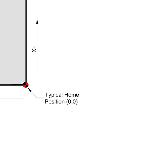
14 JointCAM Reference Guide General Settings Show/Hide Tooltips Select this option to show tooltips in JointCAM. JointCAM must be closed and restarted for this option to take effect. Disable Rabbeted Dovetail Warning Messages When cutting through dovetails, the length of the tails must be at least as long as the stock thickness. JointCAM can optionally cut a rabbet in the pin board, resulting in tails shorter than the stock thickness. If the user specifies a tail length less than the stock thickness, JointCAM will display a warning message. This gives the user 3 options: 1) Cut a rabbeted joint with the current settings 2) Increase the tail height for a full joint (If the tool is long enough) 3) Cancel the calculation to allow the settings to be changed This warning message is displayed whenever the Calculate/Preview button is pressed, as well as when the g- code is written. Selecting this option disables the warning message, and automatically defaults to a rabbeted joint. Machine Setup Clearance Plane Z height of rapid moves above workpiece during joint cutting. Note: Some rapid moves are at cut level, retracing previously cut areas to reduce cycle times. First Rapid Height Z height of first move prior to cutting. Set to a value higher than any clamps or other objects between the starting position and the work piece(s). First Rapid Height is also used after all tool changes, to protect against crashing into any clamps or holding devices after a tool change. (Also commonly referred to as Safe Z) X Axis Origin Y Axis Origin Allow the user to specify the coordinates of the Origin (Shown as 0,0 in Illustrations 2 & 3) Machine Width Width of machinable area between left and right vertical fences when cutting dovetails and box joints. See Illustrations 2 and 3. Dovetail/Box Joint Axis Select axis along which the work piece is mounted for dovetails and/or box joints. See Illustrations 2 and 3. Configuration 14 of 50

 While operating a CNC router, the user will typically stand at the front or side of the machine, on the side or end where the")
 end of the specified axis.")
 Illustration 4 displays a machine with fixtures mounted along the Y axis on the positive end (or back) of the machine.")
15 JointCAM Reference Guide Machine Width = Stock Width Selecting this option allows cutting both left and right joints using a single fence located at the origin. This is useful for machines that are not wide enough for two vertical boards, or where only one fence is available. When this option is selected, pins and tails must be cut separately when cutting half blind dovetails. Use Positive End of Machine (Rotate Origin 180 ) While operating a CNC router, the user will typically stand at the front or side of the machine, on the side or end where the Origin is located. Many machine configurations do not allow the mounting of a vertical clamping fixture on these sides of the machine. Selecting this option allows you to mount your fixture and machine joints at the positive (opposite) end of the specified axis. This effectively rotates the origin 180 from what is shown in Illustrations 2 & 3. (Moving the origin diagonally across the table) Illustration 4 displays a machine with fixtures mounted along the Y axis on the positive end (or back) of the machine. Notice that the coordinate system does not change, so moves away from the fixture origin are now negative moves rather than positive. When using the opposite end of your machine with JointCAM, be very careful if you are using the Park Position option, as the Park Position coordinates are referenced from your fixture origin coordinates. Configuration 15 of 50


 Configuration 16 of")
16 JointCAM Reference Guide File Paths Specify and Use Default G-Code folder Select this option to select a default output folder for g-code files. Use the Browse button to select the folder. If not selected, the file location should default to the last folder used (Windows default) Specify and Use Default Project Folder Select this option to select a default output folder for project files. Use the Browse button to select the folder. If not selected, the file location should default to the last folder used (Windows default) Configuration 16 of 50
17 Plunge Rate Percentage JointCAM Reference Guide Feedrate for plunge moves. Enter a percentage of the full feedrate. This applies to straight tools only. JointCAM does not plunge into the workpiece itself. For dovetail and box joints, all plunge moves outside of the workpiece are done at rapid rate. Plunge moves behind the workpiece (over the machine table) are done at the plunge rate. The user will often want to use a backer board to prevent tearout on the backside of the workpiece. The only places the tool will actually be plunging into material would be into a backer board. Plunge rate will also be used as a ramp feedrate in future releases of JointCAM, mainly when cutting mortises. Scale Feedrate Yes/No This option allows you to scale the feedrate in the exported g-code. Primarily for ShopBot users, this allows you to specify the feedrate in JointCAM in units/minute, and have the feedrate written as units/second in the g-code or.sbp code. To use, check the box, and set an appropriate scale factor. Scale Factor Feedrate scale factor. For shopbot users wanting to specify feedrate in units/minute, and export using units/second, use (1/60). Unit Conversion These options allow you to use one unit in JointCAM, and output g-code in different units. For example, some machines will only accept metric g-code, but the user may prefer to use imperial units in JointCAM. Inches to mm's Scales values by 25.4 to convert inches to mm's. mm's to Inches Scales values by 1/25.4 to convert mm's to inches. Convert Feedrate When selected, feedrates will be scaled along with selected unit conversion. To convert units only, but keep feedrates as entered, leave unchecked. ShopBot Spindle Control Shopbot Control Spindle with SO, #,# Commands When this option is selected, an SO, x, 1 followed by a Pause 3 will be added for spindle start, and SO x, 0 will be added for spindle stop. (x = output number, which is set in the Shopbot Spindle Control Section) Shopbot Use Multiple Heads Select this option if you have a Shopbot with two independent heads. This enables additional settings for the 2 nd head. Configuration 17 of 50
18 Spindle #1 Output # JointCAM Reference Guide Enter the output # for the SO command to turn the first spindle on/off. (This is typically set to 1 for a single head machine) Spindle #1 Axis Select the Axis letter for the first spindle. (Available options are Z and A) Spindle #2 Output # Enter the output # for the SO command to turn the second spindle on/off. (This is typically set to 2 for a two head machine) Spindle #2 Axis Select the Axis letter for the second spindle. (Available options are Z and A) Head #2 X Offset Enter the command for the Head 2 X axis offset, as found in your my_variables.sbc file. You must also include a + or - in front of it, to either add or subtract the offset. This would typically be -&my_xinhead2offset (if using inches) or -&my_xmmhead2offset (if using mm's). Head #2 Y Offset Enter the command for the Head 2 Y axis offset, as found in your my_variables.sbc file. You must also include a + or - in front of it, to either add or subtract the offset. This would typically be -&my_yinhead2offset (if using inches) or -&my_ymmhead2offset (if using mm's). Configuration 18 of 50

 Half Blind EQ Half Blind dovetail joints")

 Half Blind Custom Half Blind dovetail joints where pins and tails can be different sizes, with different")


19 JointCAM Reference Guide Dovetails Dovetails are one of the most common types of woodworking joints. They are commonly found on all types of furniture and cabinetry, from mass produced drawers and other types of boxes, to carcass construction on fine furniture. JointCAM offers four different options for creating dovetails: 1) Half Blind EQ Half Blind dovetail joints where pins and tails are equally spaced, similar to dovetails cut with a standard dovetail jig. With equal sized pins and tails, both pin and tail boards can be cut simultaneously, which makes for a very fast joint to machine. 2) Half Blind Custom Half Blind dovetail joints where pins and tails can be different sizes, with different spacing between them. A virtually unlimited number of joint styles can be created by specifying the sizes of each pin and tail in the joint. 3) Through EQ - Through dovetail joints where both pins and tails are equally spaced. Most hand cut dovetails are through dovetails. Through dovetails are visible on both faces of the joint. 4) Through Custom Through dovetail joints where pins and tails can be different sizes, with different spacing between them. A virtually unlimited number of joint styles can be created by specifying the sizes of each pin and tail in the joint. For a typical drawer box, the pin boards are the front and back of the drawer, with the tail boards being the drawer box sides. Illustration 5 below shows a half blind dovetail box with the locations of left and right hand joints as JointCAM refers to them. Dovetails 19 of 50


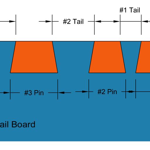
20 JointCAM Reference Guide Illustration 6 below shows a through dovetail box with the locations of left and right hand joints as JointCAM refers to them. The Half Blind Interface(s) The following descriptions cover both the Half Blind Equal and Half Blind Custom tabs in JointCAM. Some options are not available on both tabs. Dovetail Parameters Dovetails 20 of 50
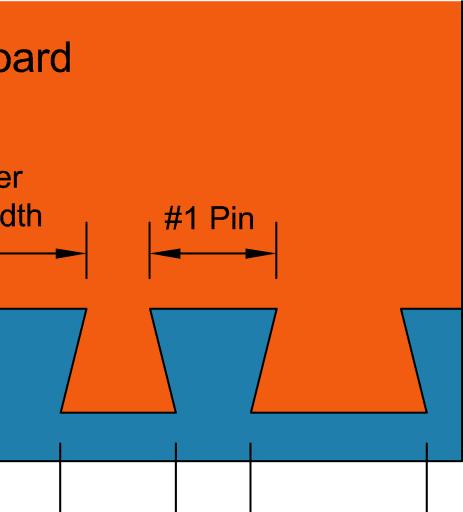
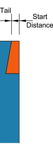
21 Width of Stock The width of the material being used. For a drawer, this is typically the drawer height. Thickness of Stock JointCAM Reference Guide The thickness of the material being used for the tail boards (mounted vertically). Note: The pin board can be any thickness greater than the depth of cut. If depth of cut is greater than the pin board thickness, JointCAM will be unaware of this situation, and will not give an error. Depth of Cut The depth of cut setting is the depth of cut into the pin board, and the height of the dovetails. Start Distance The Start Distance is the distance from the top edge of the stock to the edge of the first cut. Three options are available: ½ Tail Width Start distance will be equal to ½ the width of the tails. At their widest point.. Centered Dovetails will be centered on the stock. Start distance will be equal at the top and bottom of the stock. As many tails as possible will be used. Use this option for a symmetrical joint, where both left hand and right hand joints will be exactly the same. (Not available for Half Blind Custom dovetails, as the Symmetrical option duplicates this functionality.) Custom Enter a user defined Start Distance. An error message will be displayed if the value is less than the minimum required amount. Dovetail Type One Pass or Multi-Pass One pass dovetails use the diameter of the dovetail bit as the width of the dovetails. These are the fastest dovetail joints to cut. Both pin and tail boards can be cut simultaneously. Multi-Pass dovetails have either pins or tails that are wider than the dovetail bit, requiring multiple passes to cut. If pins and tails are different widths, pin boards and tail boards must be cut in separate operations. (Not available for Half Blind Custom dovetails.) Tail Width Width of Tails for Multi-Pass dovetails See Illustration 7 above. (Not available for Half Blind Custom dovetails.) Pin Width Width of Pins for Multi-Pass dovetails See Illustration 7 above. (Not available for Half Blind Custom dovetails.) Pins = Tails When this option is selected, pin width will automatically be set to the tail width. (Multi-Pass only) (Not available for Half Blind Custom dovetails.) Dovetails 21 of 50


 # of Tails # of tails in the")
")


22 Full Tails Only JointCAM Reference Guide When this option is selected, JointCAM will not allow a partial tail at the bottom edge of the stock. (Not available for Half Blind Custom dovetails.) # of Tails # of tails in the current layout (read only, updated with calculation) Pin/Tail Offset = When simultaneously cutting both pin boards and tail boards, the pin boards must be offset away from X zero or Y zero. A spacer of the correct width is the typical method used. Pin/Tail Offset varies with pin width and depth of cut. See Illustration 8. Scoring Pass Select this option to make a scoring cut prior to cutting the dovetails. The scoring pass should eliminate Dovetails 22 of 50

23 JointCAM Reference Guide Scoring Depth Depth of the scoring pass from face of tailboard. Clearance The Clearance value is used to adjust the fit of the dovetail joint. The Clearance is the actual space on each side of the tails, so the actual clearance space will be double the Clearance value. Positive values will increase the clearance, giving a looser fit. Negative values will decrease the clearance, giving a tighter fit. Very small clearance values can have a large effect on the fit. Start with small values if more clearance is needed ( inches, or mm's) For half blind dovetails, JointCAM adjusts the clearance by varying the cut depth. When a Clearance value is used, the actual depth of cut will vary from the entered Depth of Cut. Use Roughing Tool Selecting this option will have JointCAM create roughing passes with a straight bit. Roughing passes can result in better fitting joints on machines where flex is an issue, as roughing will result in lower cutting forces when cutting with the dovetail bit. Roughing Allowance Amount of material left to remove after roughing passes. Note: Roughing Allowance is not used for Single Pass dovetails. With Single Pass dovetails, the roughing toolpaths are single pass as well. JointCAM will give a warning if the selected straight roughing tool is too large. See Illustration 11. Dovetails 23 of 50

 JointCAM's half blind toolpaths cut into the pin board, then reverse direction 180 degrees to move out of the pin board.")
24 Roughing Depth Allowance Amount of material left at the bottom of the tail and tail socket roughing cuts. JointCAM Reference Guide Roughing Stepover % Percentage of straight tool diameter for roughing pass stepover. Roughing passes are equally spaced, with the value entered being a maximum value. Note: The first roughing pass between tails will always be a full width pass. Tail Socket Overcut The Overcut setting serves two purposes. 1) JointCAM's half blind toolpaths cut into the pin board, then reverse direction 180 degrees to move out of the pin board. On some machine controls, constant velocity settings can sometimes result in the tool reversing direction before reaching the full depth of cut. Adding a small overcut value can let the user adjust the socket depth to achieve the desired fit. 2) With dovetails, it's often desirable to cut the joints slightly deeper, then sand or trim the protruding edges of the pin boards flush to the tail board surface. Note: Actual amount of overcut may be different from the entered value. Test cuts may be required to find the correct value to achieve the desired results. Be sure to add 2 times the actual overcut to the length of the pin boards to finish with accurately sized boxes. See Illustrations 12 and 13. Dovetails 24 of 50
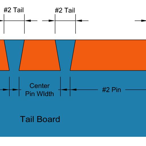
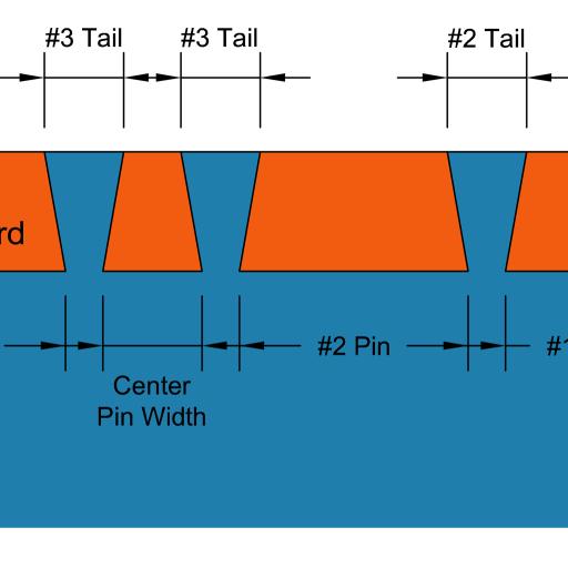
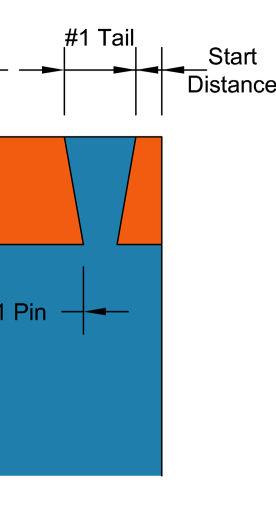
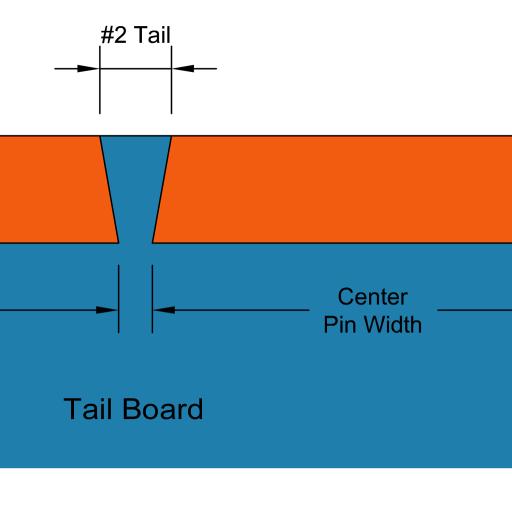
25 Calculate / Preview JointCAM Reference Guide This button calculates the joint layout and displays a preview of the joint. The preview is a view of the edge of the pin board for a left joint. Joints must be Calculated/Previewed before g-code can be exported. Note: Changes to any parameters after a preview is created WILL be reflected in the exported g-code, but the preview will NOT be updated to reflect these changes, unless the Calculate/Preview button is clicked again. Tail/Pin Data (Half Blind Custom only) See Illustrations on next page for examples. #1 Tail Width through #11 Tail Width Width of each tail. To create a tail, enter a value greater than or equal to the dovetail tool diameter. Tails must be entered in order. For example, if a value is entered for Tail #1, #2, and #4, but tail #3 is left at zero, an error will occur. #1 Pin Width through #10 Pin Width Width of each pin. A pin width must be entered for each tail width entered, except the last tail. If a value is entered for Tail #1, #2, and #3, then pin width values must be entered for Pin #1 and #2. Use Minimum Pin Width When checked, all pin widths will be equal to the dovetail tool diameter. All pin width values can be left at 0. Any entered pin width values will be ignored. Symmetrical When checked, for each tail created, a duplicate, mirrored tail will be created at the opposite side of the board. This allows for custom joints with up to 22 tails. Center Last Tail When checked, the last tail will be centered in the stock. Total # of tails will be (Tails x 2) -1. If values are entered for 3 tails, a total of 5 tails will be created. ( (3x2)-1=5 ) Center Pin Width (read only) Displays the width of the center pin for Symmetrical dovetails. When Center Last Tail is selected, the Center Pin Width will be the width of the two pins on each side of the center tail. Clear All Sets the value of all Tails and Pins to zero. Dovetails 25 of 50


26 JointCAM Reference Guide Dovetails 26 of 50

 diameter is used.")

 Flute angle of the dovetail bit.")
 Maximum depth of cut per pass for straight tools used in roughing")

27 Tool Parameters JointCAM Reference Guide The Tool Parameter section provides access to JointCAM's tool table, and also allows direct entry of tool parameters. Tool # Each tool should have a unique tool number. The tool number is only used with tool change commands. Diameter Tool diameter at cutting edges. For dovetail bits, the large (bottom) diameter is used. The dovetail diameter is critical for accurate joints. In some cases, metric dovetail bits are actually imperial sized bits, and the stated values are rounded. Be sure to enter an accurate diameter. Length Flute (cutting) length of tool. Angle (Dovetail tools only) Flute angle of the dovetail bit. Commonly available bits range between 6 and 18 degrees. Depth/Pass (straight tools only) Maximum depth of cut per pass for straight tools used in roughing operations. Actual depth of cut may be less than the entered value, as all passes are made at equal depths. Feedrate Cutting feedrate for selected tool. Note: Plunge moves for dovetail bits are done at rapid rate, outside of the workpiece. Plunge moves for straight bits outside of the workpiece are done at rapid rate. Plunge rates behind the workpiece (into possible backer boards) are done at a percentage of the feedrate specified on the Configuration page. Dovetails 27 of 50
28 JointCAM Reference Guide RPM RPM for the selected tool. Head # Only available when using ShopBot machines with multiple heads (spindles). Select the appropriate head from the drop down list. (Heads are configured on the Configuration Tab) Select Tool Button Select Tool opens the Tool table, allowing you to add/edit tools to JointCAM, and select them for use. See the Tool Table section later in this manual for more information. Machining Options JointCAM has several options available for cutting half blind dovetails. Individual boards, complete joints, or pairs of joints can all be output into a single g-code file. Pin & Tail Boards Select this option to export g-code for complete joints (both pin and tail boards together). When mounting the pin board to the machine, it must be offset away from the fence. The offset distance is the Pin/Tail Offset, displayed in the Dovetail Type section after Calculation. A wood spacer should be used to insure that the pin boards are accurately located relative to the tailboard and fence. If Include Tool and Material Comments is selected in Configuration, the Pin/Tail Offset will be included in the g-code as a comment. Note: This option is not available if pin and tail widths are not equal. For unequal pins and tail, pin and tail boards must be machined separately. Pin Boards Only Select this option to export g-code for pin boards only. When cutting pin boards only, no Pin/Tail Offset spacer is required. The pin board should mount directly against the horizontal fence, at the X or Y zero position. Tail Boards Only Select this option to export g-code for tail boards only. Left & Right Joints Select this option to export g-code for both left and right joints in one file. Half blind dovetails are cut with the inside of the joint facing out when mounted on the machine for machining. Because of this, left joints are actually machined on the right side of the machine, and right joints are machined on the left. Refer to Illustration 4 for reference. The machining options graphic displays the stock orientation as it will be mounted on the machine, based on the selected machining options. Dovetails 28 of 50
29 JointCAM Reference Guide Left Joints Only Select this option to export g-code for Left Joints only. Right Joints Only Select this option to export g-code for right joints only. Load Project Load a previously saved Project (.jnt file). JointCAM allows the users to save the current parameters for all joint types into a JointCAM Project file. See Save Project below for more information. If the Project file contains a joint type other than the currently selected joint, JointCAM will switch to the appropriate joint type and load the data for that joint. Save Project Save all options for the current joint type to a JointCAM Project file (.jnt file). This allows you to design a particular joint, and recall the joint at a later time to create g-code. The.jnt file is a simple text file. Do not attempt to edit.jnt files outside of JointCAM. Write G-Code File Click this button to export a g-code file with the selected parameters. The Write G-Code File button is disabled until a Calculation/Preview is performed. If an error is encountered during the calculation, the Write G-Code File button will remain disabled. Note: Changes to any parameters after a preview is created WILL be reflected in the exported g-code, but the preview will NOT be updated to reflect these changes, unless the Calculate/Preview button is clicked again. Save Settings Saves all available parameters for the current joint type as default settings that will be loaded each time that JointCAM is run. Note: Tool parameters will be stored as shown, and may differ from parameters stored for the tool in the tool table. To restore default tool parameters from the tool table, use the Select Tool button and re-select the tool from the tool table. Exit The Exit button will close JointCAM, with no opportunity to save any current work. Dovetails 29 of 50
30 Creating a half blind dovetail joint Creating half blind dovetails in JointCAM is a quick and easy process. JointCAM Reference Guide 1) Enter the width and thickness of the stock you'll be using. 2) Enter tool information, or select tool(s) from tool table. 3) Select the desired options. 4) Click the Calculate / Preview button to preview the joint. Adjust parameters if needed until desired joint is achieved. Calculate Preview to see the result of any changes. 5) Select Machining Options. 6) Save Project (Optional). 7) Write G-Code file. 8) Mount stock on machine. 9) Set X, Y, and Z zero positions. 10) Machine a test joint to verify fit of joint. Adjust Clearance and/or Tail Socket Overcut if needed. 11) Start Machining dovetails. On machines that have rigidity issues resulting in flex at the tool, using a straight bit to remove the bulk of material (roughing passes) prior to using the dovetail bit can result in much better joints, as the cutting forces with the dovetail bit will be much lower. An alternative to using roughing passes would be to reduce the feedrate. However, lowering the feedrate may result in reduced tool life due to excessive heat. Stock and Machine Setup Prior to machining dovetails, all stock should be prepared to a uniform thickness, and must be straight, flat and square to achieve best results. If the machine fences or jig/fixture to be used can be located in a repeatable location, then the user may find it desirable to set up a work offset to use exclusively when cutting joints with JointCAM. The user can simply add the work coordinate offset (typically G54-G59) as one of the Startup Codes on the Configuration page of JointCAM. This can greatly reduce setup time, by possibly eliminating the task of setting X and Y zero each time you machine joints with JointCAM. It's strongly recommended to make as many test cuts as needed to be sure that the machine is cutting accurate joints. Dovetails 30 of 50


 The X zero position is the rear face of the tail board,")

31 Pins and Tails JointCAM Reference Guide When machining both pins and tails, both the pin boards and tailboards must be mounted to the machine very precisely. The top end of the tailboard must be flush to the top surface of the pin board, and the end of the pin board must be tight to the rear face of the tailboard. Illustration 17 depicts a typical left joint setup on a machine setup to cut dovetails along the Y axis. The tail board mounts with the top edge against the vertical fence, which is the Y zero position. The pin board is offset away from the horizontal fence by the Pin/Tail Offset amount. A spacer block is shown. (See Illustration 7 for more information) The X zero position is the rear face of the tail board, which is also the location where the pin and tail boards meet. In JointCAM, the tailboard is located in negative X coordinates, while the pin board is located in positive X coordinates. The Z zero position is located at the top face of the pin board, which is in the same plane as the end of the tail board. Right joints are mounted against the opposite fence, in a mirror image orientation from that shown in Illustration 18. Dovetails 31 of 50
.")
 is not critical, it must be higher than the table top by a distance at least equal to the depth of cut, to prevent cutting")

32 Tail Boards Only JointCAM Reference Guide When machining tail boards only, the boards are mounted in the same locations as when machining both pins and tails. The top edge of the tail board is mounted against the vertical fence (Y zero in the illustration). Illustration 18 depicts a tail board setup for a typical left joint on a machine setup to cut dovetails along the Y axis. While the location of the end of the board (mounting height) is not critical, it must be higher than the table top by a distance at least equal to the depth of cut, to prevent cutting into the table. Using a scrap backer board equal in thickness to the pin board, will help both to reduce tearout on the backside of the tail board, and also provide a reference height for mounting the tail board. Z zero is set to the top end of the tail board. Right joints are mounted against the opposite fence, in a mirror image orientation from that shown in Illustration 19. Note: To cut both left and right joints using a single fence located at the origin, Select Machine Width = Stock Width in the JointCAM Configuration page. Dovetails 32 of 50

.")


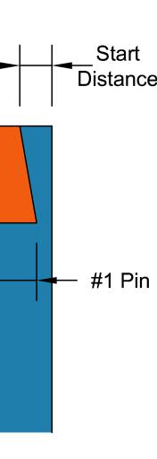
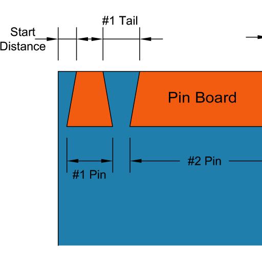
33 Pin Boards Only JointCAM Reference Guide When machining pin boards only, the edge of the pin board is mounted against the edge of the horizontal fence (Y zero in the illustration). The Pin/Tail Offset is not used, and no spacer is required. The end of the pin board is located at the edge of the vertical mounting surface (X zero in the illustration). Illustration 19 depicts a pin board setup for a typical left joint on a machine setup to cut dovetails along the Y axis. Z zero is set to the top face of the pin board. Right joints are mounted against the opposite fence, in a mirror image orientation from that shown in Illustration 20. Note: To cut both left and right joints using a single fence located at the origin, Select Machine Width = Stock Width in the JointCAM Configuration page. Dovetails 33 of 50

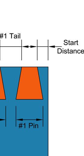
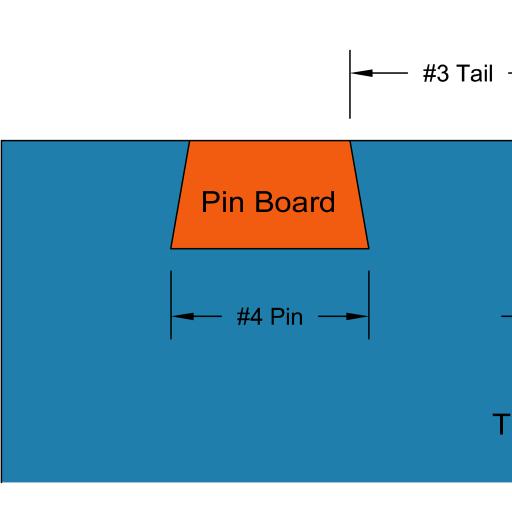
34 The Through Dovetail Interface(s) JointCAM Reference Guide The following descriptions cover both the Through Equal and Through Custom tabs in JointCAM. Some options are not available on both tabs. Dovetail Parameters Width of Stock The width of the material being used. For a drawer, this is typically the drawer height. Thickness of Stock The thickness of the material being used for both the pin and tail boards. Currently both pin and tail boards must be the same thickness. Tail Height With through dovetails, the tail height is normally equal to the stock thickness. However, JointCAM offers an alternate through dovetail with a tail height less than the stock thickness. This is accomplished by cutting a rabbet on the inside of the pin board, which reduces the tail height. This allows you to cut a through dovetail when available tools are shorter than the stock thickness, or to achieve a specific look. Tail Width Width of Tails. (Not available for Through Custom dovetails.) Pin Width Width of Pins. (Not available for Through Custom dovetails.) Pin/Tail Extension Distance that both pins and tails will extend past the corner of the assembled joint. Cutting the pins and tails slightly long allows the extra material to be trimmed away after assembly, giving more consistent quality joints. Dovetails 34 of 50
35 Pins /Tails = Tool JointCAM Reference Guide When this option is selected, both tail and pin widths will automatically be set to diameter of the currently selected tool. Note: Changing the tool after selecting this option will not update the pin and tail widths. (Not available for Through Custom dovetails.) Pins = Tails When this option is selected, pin width will automatically be set to the tail width. (Not available for Through Custom dovetails.) Start Distance The Start Distance for through dovetails is either the distance from the top edge of the stock to the edge of the first tail (when Tails First is selected) or the width of the first pin (when Pins First is selected). (See Configuration option below) Three Start Distance options are available: ½ Tail Width Start distance will be equal to ½ the width of the tails at their widest point (top). Centered Dovetails will be centered on the stock. Start distance will be equal at the top and bottom of the stock. As many tails as possible will be used. Use this option for a symmetrical joint, where both left hand and right hand joints will be exactly the same. (Not available for Through Custom dovetails, as the Symmetrical option duplicates this functionality.) Custom Enter a user defined Start Distance. When Tails First is selected, an error message will be displayed if the value is less than the minimum required amount. Configuration (Pin First or Tail first) Unlike half blind dovetails, which always start with a pin, through dovetails give you the option to start with either a pin or tail. Roughing Options The roughing options for through dovetails are the same as for half blind dovetails. Please see the half blind section for more information. Clearance See the half blind Clearance section for more information. For through dovetails, JointCAM adjusts the clearance by varying the width of the pins. Tail size and spacing remains as specified. Calculate / Preview This button calculates the joint layout and displays a preview of the joint. The preview for through dovetails displays a side view of the end of the tail board for a right joint. Joints must be Calculated/Previewed before g-code can be exported. Note: Changes to any parameters after a preview is created WILL be reflected in the exported g-code, but the preview will NOT be updated to reflect these changes, unless the Calculate/Preview button is clicked again. Dovetails 35 of 50
36 JointCAM Reference Guide Tail/Pin Data (Through Custom only) See Illustrations for examples. #1 Tail Width through #11 Tail Width Width of each tail. To create a tail, enter a value greater than or equal to the dovetail tool diameter. Tails must be entered in order. For example, if a value is entered for Tail #1, #2, and #4, but tail #3 is left at zero, an error will occur. #1 Pin Width through #10 Pin Width Width of each pin. A pin width must be entered for each tail width entered, except the last tail. If a value is entered for Tail #1, #2, and #3, then pin width values must be entered for Pin #1 and #2. Note: The location of the Pin and Tail width input boxes (text boxes) will change to reflect the setting of the Pin First / Tail First Configuration. Use Minimum Pin Width When checked, all pin widths will be equal to the dovetail tool diameter. All pin width values can be left at 0. Any entered pin width values will be ignored. Symmetrical When checked, for each tail created, a duplicate, mirrored tail will be created at the opposite side of the board. This allows for custom joints with up to 22 tails. Center Last Tail When checked, the last tail will be centered in the stock. Total # of tails will be (Tails x 2) -1. If values are entered for 3 tails, a total of 5 tails will be created. ( (3x2)-1=5 ) Note: When Tails First is selected, 2 additional partial tails will be added to the quantities mentioned above. Center Pin Width (read only) Displays the width of the center pin for Symmetrical dovetails. When Center Last Tail is selected, the Center Pin Width will be the width of the two pins on each side of the center tail. Clear All Sets the value of all Tails and Pins to zero. Dovetails 36 of 50


37 JointCAM Reference Guide Dovetails 37 of 50


38 JointCAM Reference Guide Dovetails 38 of 50
39 Tool Parameters JointCAM Reference Guide The tool parameters for through dovetails are the same as explained in the half blind dovetail section. However, when machining through dovetails, the pin boards are cut with a straight bit only. With through dovetails, the minimum tail width is limited by the diameter of the selected dovetail bit, while the minimum tail width is limited by the diameter of the selected straight bit. Machining Options JointCAM has several options available for machining through dovetails. Individual boards, or pairs of joints can be output into a single g-code file. Both boards are machined vertically, and must be machined in separate operations. Pin Boards Only Select this option to export g-code for pin boards only. Tail Boards Only Select this option to export g-code for tail boards only. Left & Right Joints Select this option to export g-code for both left and right joints in one file. The mounting orientations for through dovetails are different than for half blind dovetails. Pin boards are machined with the inside of the joint facing out when mounted on the machine. Tail boards are machined with the outside face facing out. Right joints are machined on the right side of the machine, and left joints are machined on the left. Refer to Illustration 4 for reference. The machining options graphic displays the stock orientation as it will be mounted on the machine, based on the selected machining options. Left Joints Only Select this option to export g-code for Left Joints only. Right Joints Only Select this option to export g-code for right joints only. Multiple Tails Selecting this option allows you to cut multiple tail boards in one operation. Enter the quantity of boards to be cut simultaneously. The toolpath length is calculated by multiplying the stock thickness x quantity entered. This option can also be used if a backer board is to be mounted outside of the stock, to have the toolpath move straight through the backer board. Dovetails 39 of 50
40 Load Project JointCAM Reference Guide Load a previously saved Project (.jnt file). JointCAM allows the users to save the current parameters for all joint types into a JointCAM Project file. See Save Project below for more information. If the Project file contains a joint type other than the currently selected joint, JointCAM will switch to the appropriate joint type and load the data for that joint. Save Project Save all options for the current joint type to a JointCAM Project file (.jnt file). This allows you to design a particular joint, and recall the joint at a later time to create g-code. The.jnt file is a simple text file. Do not attempt to edit.jnt files outside of JointCAM. Write G-Code File Click this button to export a g-code file with the selected parameters. The Write G-Code File button is disabled until a Calculation/Preview is performed. If an error is encountered during the calculation, the Write G-Code File button will remain disabled. Note: Changes to any parameters after a preview is created WILL be reflected in the exported g-code, but the preview will NOT be updated to reflect these changes, unless the Calculate/Preview button is clicked again. Save Settings Saves all available parameters for the current joint type as default settings that will be loaded each time that JointCAM is run. Note: Tool parameters will be stored as shown, and may differ from parameters stored for the tool in the tool table. To restore default tool parameters from the tool table, use the Select Tool button and re-select the tool from the tool table. Exit The Exit button will close JointCAM, with no opportunity to save any current work. Dovetails 40 of 50


41 Creating a through dovetail joint JointCAM Reference Guide Creating through dovetails in JointCAM is very similar to creating half blind dovetails. The main difference is that pins and tails must be cut separately, and both boards are mounted vertically. On machines that have rigidity issues resulting in flex at the tool, using a straight bit to remove the bulk of material (roughing passes) prior to using the dovetail bit can result in much better joints, as the cutting forces with the dovetail bit will be much lower. An alternative to using roughing passes would be to reduce the feedrate. However, lowering the feedrate may result in reduced tool life due to excessive heat. Pin Boards When machining pin boards, the TOP edge of the pin board is mounted against the edge of the vertical fence (Y zero in the illustration). Z zero is set to the top face of the pin board. Right joints are mounted against the right side fence, as shown in Illustration 28. Left joints are mounted against the left side fence, in a mirror image orientation from that shown in Illustration 28. Note: To cut both left and right joints using a single fence located at the origin, Select Machine Width = Stock Width in the JointCAM Configuration page. Dovetails 41 of 50


42 Tail Boards JointCAM Reference Guide When machining tail boards, the TOP edge of the tail board is mounted against the edge of the vertical fence (Y zero in the illustration). Z zero is set to the top face of the pin board. Right joints are mounted against the right side fence, with the outside face facing out, as shown in Illustration 29. Left joints are mounted against the left side fence, in a mirror image orientation from that shown in Illustration 29. Note: To cut both left and right joints using a single fence located at the origin, Select Machine Width = Stock Width in the JointCAM Configuration page. Only one side can be cut at a time. Dovetails 42 of 50


 Rounded box joints Similar to standard box joints, with fingers rounded on the back edge.")
 Double Round box joints A half blind box joint where the fingers are rounded at their ends as")

43 JointCAM Reference Guide Standard Box Joints Box joints (also known as finger joints) are a simpler alternative to dovetail joints. They are very strong, due to the large glue surface area, and very simple to cut on a CNC router. Box joints have traditionally been cut with table saw or router table jigs. JointCAM can create tool paths and g-code for 3 types of box joint: 1) Standard box joints Box joints with standard rectangular shaped interlocking fingers. JointCAM gives you several layout options, allowing you to create an unlimited variety of joint designs. 2) Rounded box joints Similar to standard box joints, with fingers rounded on the back edge. One board is cut in the horizontal position to accept a rounded socket. 3) Double Round box joints A half blind box joint where the fingers are rounded at their ends as well as in between them. Illustration 30 below depicts a typical box using standard box joints, with the joints and boards labeled as JointCAM refers to them. Note that board A always starts with a finger at the top of the joint. Both left and right joints can be cut in each others machine location, by keeping the top edge against the vertical fence. Standard Box Joints 43 of 50


 finger of the A board.")
 in size being uniform for each finger in the joint. The smaller of the two values will be the actual size entered.")
44 The Standard Box Joint Interface JointCAM Reference Guide The following descriptions cover both the Half Blind Equal and Half Blind Custom tabs in JointCAM. Some options are not available on both tabs. Box Joint Parameters Width of Stock The width of the material being used. For a drawer, this is typically the drawer height. Thickness of Stock The thickness of the material being used for the box joints. The thickness is also the depth of cut. Finger #1 Width & Finger #2 Width How these values are used depends on the Layout Type chosen by the user. Three different Layout Types use these values: 1) For an Equal layout, the Finger #1 Width is the width of all fingers in both A and B boards. Finger #2 Width is not used with Equal Layouts. (See Start Distance below for changing the top finger width of the A board. 2) For a Graduated Layout, the Finger #1 Width is the width of the first (top) finger of the A board. Finger #2 Width is the width of the last (bottom) finger of the A board. JointCAM will gradually increase or decrease the width of the fingers from the first finger (#1) to the last finger (#2), with the increase (or decrease) in size being uniform for each finger in the joint. The smaller of the two values will be the actual size entered. The larger of the two values will most often be an approximate value, and may be slightly larger or smaller than the specified value, in order to provide a uniform increase in finger widths. Standard Box Joints 44 of 50
45 JointCAM Reference Guide 3) For a Graduated-Mirrored Layout, the Finger #1 width is the width of both the first (top) and last (bottom) fingers of the joint. The Finger #2 Width is the width of the center finger in the joint. JointCAM will gradually increase or decrease the width of the fingers from the first finger (#1), to the center finger (#2) and back to the last finger (#1 again), with the increase in size being uniform for each finger in the joint. As with the Graduated Layout, the smaller of the two values will be the actual size entered. The larger of the two values will most often be an approximate value, and may be slightly larger or smaller than the specified value, in order to provide a uniform increase in finger widths. Finger Extension An allowance to the depth of cut, to allow for trimming the assembled joint flush. Start Distance The Start Distance sets the width of the first finger at top edge of the A board. Start Distance is only used for Equal Layouts. Three options are available: Full Finger First finger will be the same size as all other fingers, as specified in Finger #1 Width setting. Centered First and last fingers will be equal, with all other fingers being equal to Finger #1 Width. The first and last finger widths will be less than or equal to the Finger #1 width. Custom Enter a user defined width for the first finger. All other fingers will be equal to the Finger #1 width. Layout Type JointCAM has four options for laying out your box joints: Equal All fingers will be equal in width, as specified in Finger #1 Width setting. There are two exceptions. The first finger width can be modified with the Start Distance settings, and the last finger width is dictated by the stock width. Graduated Fingers will gradually increase or decrease in width across the joint. Graduated-Mirrored Fingers will gradually increase or decrease in width across the joint from the edge to the center, and then again to the opposite edge in a mirrored pattern. Custom Allows the user to enter a user defined width for each finger. The space between the fingers are labeled as Sockets, and are the widths of the fingers of the B board. See Finger #1 Width & Finger #2 Width settings above for more information on the Graduated and Graduated- Mirrored Layout Types. Finger Width Data Parameters for Custom Layout Type box joints. Finger and Socket width entry boxes Each Finger and socket ( B finger) width can be entered for a truly custom appearance. Standard Box Joints 45 of 50
46 Sockets = Fingers JointCAM Reference Guide When this option is selected, each socket ( B finger) width will be equal to the preceding finger width. This also doubles the available number of finger width entry boxes. Sockets = Tool Diameter When this option is selected, each socket ( B finger) width will be equal to the tool diameter. This also doubles the available number of finger width entry boxes. Symmetrical When this option is selected, each finger and socket will be mirrored at the opposite edge of the board. Center Finger/Socket Width A read-only display of the width of the center finger or socket in a Symmetrical joint. Useful for fine tuning finger widths. Tool Parameters The Tool Parameter section provides access to JointCAM's tool table, and also allows direct entry of tool parameters. Box joints only require a single straight tool. The available parameters are described below. Tool # Each tool should have a unique tool number. The tool number is only used with tool change commands. Diameter Tool diameter at cutting edges. For dovetail bits, the large (bottom) diameter is used. The dovetail diameter is critical for accurate joints. In some cases, metric dovetail bits are actually imperial sized bits, and the stated values are rounded. Be sure to enter an accurate diameter. Length Flute (cutting) length of tool. Depth/Pass (straight tools only) Maximum depth of cut per pass for straight tools used in roughing operations. Actual depth of cut may be less than the entered value, as all passes are made at equal depths. Feedrate Cutting feedrate for selected tool. Plunge moves for straight bits outside of the workpiece are done at rapid rate. Plunge rates behind the workpiece (into possible backer boards) are done at a percentage of the feedrate specified on the Configuration page. RPM RPM for the selected tool. Standard Box Joints 46 of 50
47 Select Tool Button JointCAM Reference Guide Select Tool opens the Tool table, allowing you to add/edit tools to JointCAM, and select them for use. See the Tool Table section later in this manual for more information. Machining Options JointCAM has several options available for cutting box joints. Individual boards, complete joints, or pairs of joints can all be output into a single g-code file. Box joints are cut with both boards in the vertical position. Finger Board A Select this option to export g-code for A boards only. The board should be mounted directly against the vertical fence, at the X or Y zero position (or the opposite side fence). The exterior face of the A board should be facing out when mounted. Finger Board B Select this option to export g-code for B boards only. The board should be mounted directly against the vertical fence, at the X or Y zero position (or the opposite side fence). The interior face of the B board should be facing out when mounted. A and B Boards Select this option to export g-code for complete joints (both A and B boards together). The A board is positioned against the vertical mounting surface, with the edge against the vertical fence. The B board is placed in front of the A board, offset from the vertical fence by the width of the first finger. Note: This option is only available for Equal layouts, with the first finger set to full finger. For all other layout types, both A and B boards must be machined separately. Multiple Boards When this option is selected, multiple identical A or B boards can be cut simultaneously. Enter the number of boards to be cut, and JointCAM will create a tool path to accommodate the chosen number of boards. Be sure the machine has the capability to reach over the multiple boards. Left & Right Joints Select this option to export g-code for both left and right joints in one file. Left Joints Only Select this option to export g-code for Left Joints only. Right Joints Only Select this option to export g-code for right joints only. Standard Box Joints 47 of 50
48 Load Project JointCAM Reference Guide Load a previously saved Project (.jnt file). JointCAM allows the users to save the current parameters for all joint types into a JointCAM Project file. See Save Project below for more information. If the Project file contains a joint type other than the currently selected joint, JointCAM will switch to the appropriate joint type and load the data for that joint. Save Project Save all options for the current joint type to a JointCAM Project file (.jnt file). This allows you to design a particular joint, and recall the joint at a later time to create g-code. The.jnt file is a simple text file. Do not attempt to edit.jnt files outside of JointCAM. Write G-Code File Click this button to export a g-code file with the selected parameters. The Write G-Code File button is disabled until a Calculation/Preview is performed. If an error is encountered during the calculation, the Write G-Code File button will remain disabled. Note: Changes to any parameters after a preview is created WILL be reflected in the exported g-code, but the preview will NOT be updated to reflect these changes, unless the Calculate/Preview button is clicked again. Save Settings Saves all available parameters for the current joint type as default settings that will be loaded each time that JointCAM is run. Note: Tool parameters will be stored as shown, and may differ from parameters stored for the tool in the tool table. To restore default tool parameters from the tool table, use the Select Tool button and re-select the tool from the tool table. Exit The Exit button will close JointCAM, with no opportunity to save any current work. Standard Box Joints 48 of 50


49 The JointCAM Tool Table JointCAM Reference Guide JointCAM has a tool table where the user can store and edit tool information, and quickly import the tool parameters into a project. Adding Tools to the tool table To add tools to the tool table, enter the tool information in the Add/Edit tool section, and click the Save Tool button. Editing Tools in the tool table To edit tool information, select a tool in the table by clicking on it to highlight the row that it's on. Once highlighted, click the Edit Tool button to load the tool into the Add Edit tool area. Note: This will remove the tool from the tool table during editing. Once any changes are made, click Save Tool to save the tool back to the tool table. If the Save Tool button is not clicked, the tool will not be restored to the table. Note: After any changes have been made to the tool table, the Save Tool Table button must be clicked to save the changes. If the Save Tool Table button is not clicked, all changes will be lost. A message will warn the user if the table has not been saved. Deleting Tools from the tool table To delete a tool from the tool table, select it by clicking on the tool to highlight the row that it's on, and click the Delete Tool button. The JointCAM Tool Table 49 of 50
JointCAM Reference Guide. JointCAM. Reference Guide. Version 1.02 Copyright G-Force CNC, LLC, All Rights Reserved. 1 of 40
 JointCAM Reference Guide JointCAM Reference Guide Version 1.02 Copyright G-Force CNC, LLC, 2014. All Rights Reserved. 1 of 40 JointCAM Reference Guide Disclaimer All CNC machines are potentially dangerous.
86N80.10 Economy Dovetail Jig
 86N80.10 Economy Dovetail Jig IMPORTANT: Before using your dovetail jig, it should be securely fastened to a workbench. For a temporary setup, attach the jig to a piece of ¾ thick plywood or MDF long and
Figure 1: NC EDM menu
 Click To See: How to Use Online Documents SURFCAM Online Documents 685)&$0Ã5HIHUHQFHÃ0DQXDO 6 :,5(('0 6.1 INTRODUCTION SURFCAM s Wire EDM mode is used to produce toolpaths for 2 Axis and 4 Axis EDM machines.
Single Pass Half-Blind Dovetails
 9 DR Pro - CHAPTER Single Pass Half-Blind Dovetails Why rout single pass dovetails on a variable spaced Leigh jig? Well, you just may need to reproduce or restore a late 9th or early 0th century drawer
Complete Dovetail Jig Instructions
 Complete Dovetail Jig Instructions 15 18 4 3 1 12 13 8 19 17 16 6 14 5 9 11 10 2 9 PARTS LIST - Complete Dovetail Jig Introduction Your new dovetail jig will cut Full Through Dovetails and three varieties
CHAPTER 10. Half-Blind Dovetail Procedures
 CHAPTER 0 Half-Blind Dovetail Procedures 6 Chapter 0 D User Guide HALF-BLIND DOVETAIL PROCEDURES Chapter Foreword In these instructions for using the Leigh Dovetail Jig, we have recommended using certain
Conversational CAM Manual
 Legacy Woodworking Machinery CNC Turning & Milling Machines Conversational CAM Manual Legacy Woodworking Machinery 435 W. 1000 N. Springville, UT 84663 2 Content Conversational CAM Conversational CAM overview...
MAXYM Dovetailer Operating Manual
 MAXYM Dovetailer Operating Manual 1 2 Visual Tour Front View Touch Screen Blow Off Control Power Switch Air Pressure Control Air Clamp Controls Stop Button Start Cycle Button Top Table Air Clamp Controls
Copyright 2007 MLCS 1
 Copyright 2007 MLCS 1 REFERENCE GUIDE and SPECIFICATIONS: Edge Guides: This 12 Dovetail Template comes complete with 2 Edge Guide Sets one set for Half Blind and one set for Rabbeted Half Blind Dovetails.
Performance. CNC Turning & Milling Machine. Conversational CAM 3.11 Instruction Manual
 Performance CNC Turning & Milling Machine Conversational CAM 3.11 Instruction Manual Legacy Woodworking Machinery 435 W. 1000 N. Springville, UT 84663 Performance Axis CNC Machine 2 Content Warranty and
Fusion 360 Part Setup. Tutorial
 Fusion 360 Part Setup Tutorial Table of Contents MODEL SETUP CAM SETUP TOOL PATHS MODEL SETUP The purpose of this tutorial is to demonstrate start to finish, importing a machineable part to generating
CNC Applications. Programming Machining Centers
 CNC Applications Programming Machining Centers Planning and Programming Just as with the turning center, you must follow a series of steps to create a successful program: 1. Examine the part drawing thoroughly
Digital Media Tutorial Written By John Eberhart
 MadCAM MadCAM 5.0: Large 4.1: Large & Medium CNC Tool CNC Path Tool Path Generator Generator Digital Media Tutorial Written By John Eberhart MadCAM is a tool path generator that works inside Rhino. It
CAMWorks How To Create CNC G-Code for CO2 Dragsters
 Creating the Left Side Smooth Finish Tool Path. This chapter will focus on the steps for creating the left side smooth finish tool path. The objective of this chapter is to create to an accurate and highly
End-On-End Dovetails D4R - CHAPTER 12
 D4R - CHAPTER End-On-End Dovetails 4 While you have the router set up for half-blind dovetails, it is a good time to try end-on-end dovetails. If you have not yet routed half-blind dovetails or read through
ENGI 7962 Mastercam Lab Mill 1
 ENGI 7962 Mastercam Lab Mill 1 Starting a Mastercam file: Once the SolidWorks models is complete (all sketches are Fully Defined), start up Mastercam and select File, Open, Files of Type, SolidWorks Files,
Extendable Large Dovetail Jig
 Extendable Large Dovetail Jig Instruction Manual Part # 3458 CAUTION: Please read, understand, and follow all manufacturers instructions, guidelines and owners manuals that come with your power tools.
Care and Maintenance of Milling Cutters
 The Milling Machine Care and Maintenance of Milling Cutters The life of a milling cutter can be greatly prolonged by intelligent use and proper storage. Take care to operate the machine at the proper speed
When the machine makes a movement based on the Absolute Coordinates or Machine Coordinates, instead of movements based on work offsets.
 Absolute Coordinates: Also known as Machine Coordinates. The coordinates of the spindle on the machine based on the home position of the static object (machine). See Machine Coordinates Absolute Move:
MAXYM Mortiser Operating Manual
 MAXYM Mortiser Operating Manual Rev 2.112/16/02 Copyright MAXYM Technologies Inc. Table of Contents Visual Tour 1-2 Operating the Maxym Mortiser 3 Starting the Mortiser 3 Touch Screen Description 3 Mortise
CAD/CAM/CAE Computer Aided Design/Computer Aided Manufacturing/Computer Aided Manufacturing. Part-10 CNC Milling Programming
 CAD/CAM/CAE Computer Aided Design/Computer Aided Manufacturing/Computer Aided Manufacturing Part-10 CNC Milling Programming To maximize the power of modern CNC milling machines, a programmer has to master
PRAZI USA. Model PR-3900 Owners Manual. Please read this manual in its entirety before using the PRAZI ChestMate.
 PRAZI USA Model PR-3900 Owners Manual Please read this manual in its entirety before using the PRAZI ChestMate. PRAZI USA 214 Rear South Meadow Rd (800)-262-0211 Plymouth MA, 02360 www.praziusa.com ChestMate
Figure 1: NC Lathe menu
 Click To See: How to Use Online Documents SURFCAM Online Documents 685)&$0Ã5HIHUHQFHÃ0DQXDO 5 /$7+( 5.1 INTRODUCTION The lathe mode is used to perform operations on 2D geometry, turned on two axis lathes.
Touch Probe Cycles itnc 530
 Touch Probe Cycles itnc 530 NC Software 340 420-xx 340 421-xx User s Manual English (en) 4/2002 TNC Models, Software and Features This manual describes functions and features provided by the TNCs as of
MadCAM 2.0: Drill Pattern Toolpath
 MadCAM 2.0: Drill Pattern Toolpath Digital Media Tutorial 2005-2006 MadCAM 2.0 can create a toolpath to drill holes directly into your material. The bit plunges in and out of the material without moving
Woodline USA Woodline Spacer Fence System
 Woodline USA Woodline Spacer Fence System MADE IN THE USA Includes: (1) ¼ Spacer Fence (1) 3/8 Spacer Fence (1) ½ Spacer Fence (1) Hardware Package (1) 3 Piece Brass bar set (2) Setup Blocks Visit Us Online
Touch Probe Cycles TNC 426 TNC 430
 Touch Probe Cycles TNC 426 TNC 430 NC Software 280 472-xx 280 473-xx 280 474-xx 280 475-xx 280 476-xx 280 477-xx User s Manual English (en) 6/2003 TNC Model, Software and Features This manual describes
Ladybird Project - Vacuum Mould
 - Vacuum Mould Prerequisite Mould drawn and saved as an STL file in SolidWorks Focus of the Lesson On completion of this exercise you will have: Opened an STL file Set Machining Constraints Set up Tools
Half-Blind Isoloc Joint Procedures
 ISOLOC - CHAPTER 6 Half-Blind Isoloc Joint Procedures 6- Always use scrap boards to practice and test for fit. Rip the boards to width to suit the chosen template. The pin boards should not be less than
Copyright MLCS 1
 Copyright 2007. MLCS 1 WORKING WITH BOX JOINTS Box joints (AKA "Finger Joints") provide a simple, yet equally effective, alternative to dovetail joinery. In particular, they serve well for applications
Mill OPERATING MANUAL
 Mill OPERATING MANUAL 2 P a g e 7/1/14 G0107 This manual covers the operation of the Mill Control using Mach 3. Formatting Overview: Menus, options, icons, fields, and text boxes on the screen will be
CNC Router Part 2 Training Tutorial
 CNC Router Part 2 Training Tutorial Prepared by Steve Pilon - Version 1.1 September 2017 A Index B - Intro A- Index B- Intro C- Objective D- Required Items E- Opening CamBam and Loading a DXF F- Preparing
CNC Machines Assembly Guide
 CNC Machines Assembly Guide Contents Warnings 3 General Safety 3 Emergency Stop Restart Procedure 3 Before you start 4 Matrix Micro CNC Kits & Machines Modules 4 Assembly Notes 5 Small and Large Retaining
527F CNC Control. User Manual Calmotion LLC, All rights reserved
 527F CNC Control User Manual 2006-2016 Calmotion LLC, All rights reserved Calmotion LLC 21720 Marilla St. Chatsworth, CA 91311 Phone: (818) 357-5826 www.calmotion.com NC Word Summary NC Word Summary A
for Solidworks TRAINING GUIDE LESSON-9-CAD
 for Solidworks TRAINING GUIDE LESSON-9-CAD Mastercam for SolidWorks Training Guide Objectives You will create the geometry for SolidWorks-Lesson-9 using SolidWorks 3D CAD software. You will be working
Computation & Construction Lab. Stinger CNC 3D Milling Workflow
 Computation & Construction Lab Stinger CNC 3D Milling Workflow 3D Single Sided Milling Guidelines - The following steps will guide the user on how to transfer digital work from a design software to setting
Flip for User Guide. Inches. When Reliability Matters
 Flip for User Guide Inches by When Reliability Matters Mastercam HSM Performance Pack Tutorial 1 Mastercam HSM Performance Pack Tutorial Tutorial I... 2 Getting started... 2 Tools used... 2 Roughing...
Prasanth. Lathe Machining
 Lathe Machining Overview Conventions What's New? Getting Started Open the Part to Machine Create a Rough Turning Operation Replay the Toolpath Create a Groove Turning Operation Create Profile Finish Turning
Standard. CNC Turning & Milling Machine Rev 1.0. OM5 Control Software Instruction Manual
 Standard CNC Turning & Milling Machine Rev 1.0 OM5 Control Software Instruction Manual Legacy Woodworking Machinery 435 W. 1000 N. Springville, UT 84663 Standard CNC Machine 2 Content Warranty and Repair
VisualCAM 2018 TURN Quick Start MecSoft Corporation
 2 Table of Contents About this Guide 4 1 About... the TURN Module 4 2 Using this... Guide 4 3 Useful... Tips 5 Getting Ready 7 1 Running... VisualCAM 2018 7 2 About... the VisualCAD Display 7 3 Launch...
Block Delete techniques (also called optional block skip)
") Block Delete techniques (also called optional block skip) Many basic courses do at least acquaint novice programmers with the block delete function As you probably know, when the control sees a slash code
Block Delete techniques (also called optional block skip) Many basic courses do at least acquaint novice programmers with the block delete function As you probably know, when the control sees a slash code
LinuxCNC Help for the Sherline Machine CNC System
 WEAR YOUR SAFETY GLASSES FORESIGHT IS BETTER THAN NO SIGHT READ INSTRUCTIONS BEFORE OPERATING LinuxCNC Help for the Sherline Machine CNC System LinuxCNC Help for Programming and Running 1. Here is a link
Advantages, Function and Characteristics of the DMwriter MX.
 DMwriter MX All-in One Overview Advantages, Function and Characteristics of the DMwriter MX. The DMwriter MX Marking Head was designed as an easy to use, economical, spindle actuated permanent marking
Flip for User Guide. Metric. When Reliability Matters
 Flip for User Guide Metric by When Reliability Matters Mastercam HSM Performance Pack Tutorial 1 Mastercam HSM Performance Pack Tutorial Tutorial I... 2 Getting started... 2 Tools used... 2 Roughing...
15 Dovetail Jig. Instruction Manual. Part # 3452
 15 Dovetail Jig Instruction Manual Part # 3452 CAUTION: Please read, understand, and follow all manufacturers instructions, guidelines and owners manuals that come with your power tools. Peachtree Woodworking
CNC Turning Training CNC MILLING / ROUTING TRAINING GUIDE. Page 1
 CNC Turning Training www.denford.co.uk Page 1 Table of contents Introduction... 3 Start the VR Turning Software... 3 Configure the software for the machine... 4 Load your CNC file... 5 Configure the tooling...
BSketchList 3D. BSoftware for the Design and Planning of Cabinetry and Furniture RTD AA. SketchList Inc.
 1 BSketchList 3D 1 BSoftware for the Design and Planning of Cabinetry and Furniture 2 RTD10000651AA 2 Overview of SketchList 3D SketchList 3D is a software program that aids woodworkers in the design and
NZX NLX
 NZX2500 4000 6000 NLX1500 2000 2500 Table of contents: 1. Introduction...1 2. Required add-ins...1 2.1. How to load an add-in ESPRIT...1 2.2. AutoSubStock (optional) (for NLX configuration only)...3 2.3.
Standards for g-codesource.com Woodworking Programs g-codesource.com
 Standards for g-codesource.com Woodworking Programs 2012 g-codesource.com 1/28/2012 This document is for developers of g-codesource.com g-code programs; defining standard practices in program structure,
CNC PROGRAMMING WORKBOOK. Sample not for. Distribution MILL & LATHE. By Matthew Manton and Duane Weidinger
 CNC PROGRAMMING WORKBOOK MILL & LATHE By Matthew Manton and Duane Weidinger CNC Programming Workbook Mill & Lathe Published by: CamInstructor Incorporated 330 Chandos Crt. Kitchener, Ontario N2A 3C2 www.caminstructor.com
Essential BOX JOINT JIG
 Essential BOX JOINT JIG Home in on precise finger joints with this table saw sled. By Ken Burton The box (or finger) joint is a remarkably strong, interlocking corner joint that can be quickly made on
Table of Contents. Table of Contents. Preface 11 Prerequisites... 12
 Table of Contents Preface 11 Prerequisites... 12 Basic machining practice experience... 12 Controls covered... 12 Limitations... 13 The need for hands -on practice... 13 Instruction method... 13 Scope...
Revit Structure 2012 Basics:
 SUPPLEMENTAL FILES ON CD Revit Structure 2012 Basics: Framing and Documentation Elise Moss autodesk authorized publisher SDC PUBLICATIONS www.sdcpublications.com Schroff Development Corporation Structural
Operations Manual for Machines Equipped with a Rotary Axis Supplement to the WinCNC Operations Manual. 6/1/2015 Laguna Tools
 Operations Manual for Machines Equipped with a Rotary Axis Supplement to the WinCNC Operations Manual 6/1/2015 Laguna Tools TABLE OF CONTENTS Overview... 3 Safety Warning... 3 Preliminary Checks... 4 Verify
CHAPTER 8. Through Dovetail Procedures
 CHAPTER Through Dovetail Procedures 52 Chapter D4 User Guide THROUGH DOVETAIL PROCEDURES Chapter Foreword In these instructions for using the Leigh Dovetail Jig, we have recommended using certain cutters
Carcase Construction. Choosing and making the right joints. by Tage Frid
 Carcase Construction Choosing and making the right joints by Tage Frid Furniture construction is broken down into two main categories: frame and carcase. In frame construction, relatively narrow boards
WARNING: Read these instructions before using the machine DOVETAIL JIG MODEL NO: CDTJ12 / CDTJ24 PART NO: ,
 WARNING: Read these instructions before using the machine DOVETAIL JIG MODEL NO: CDTJ12 / CDTJ24 PART NO: 6462170, 6462175 OPERATION & MAINTENANCE INSTRUCTIONS LS0111 INTRODUCTION Thank you for purchasing
Ten Essential. These bits will conquer the majority of woodworking tasks. b y G a r y R o g o w s k i. Operating: handheld vs.
 Ten Essential Router Bits These bits will conquer the majority of woodworking tasks b y G a r y R o g o w s k i You ve bought a new router, unpacked it, and even found the switch on it. But that s only
The ShopBot Indexer. Contents
 ShopBot Indexer Page -1- The ShopBot Indexer The ShopBot Indexer is basically a lathe with an extra level of precision built in you can precisely control the rotation of the headstock and also link it
Using Siemens NX 11 Software. The connecting rod
 Using Siemens NX 11 Software The connecting rod Based on a Catia tutorial written by Loïc Stefanski. At the end of this manual, you should obtain the following part: 1 Introduction. Start NX 11 and open
Revit Structure 2013 Basics
 Revit Structure 2013 Basics Framing and Documentation Elise Moss Supplemental Files SDC P U B L I C AT I O N S Schroff Development Corporation Better Textbooks. Lower Prices. www.sdcpublications.com Tutorial
CNC Router Tutorial Jeremy Krause
 CNC Router Tutorial Jeremy Krause Jeremy.Krause@utsa.edu Usage prerequisites: Any user must have completed the machine shop portion of the Mechanical Engineering Manufacturing course (undergraduate, sophomore
Congratulations on your purchase of the Divided Light Door Set. This set will help you create beautiful cabinet doors with true divided light panels.
 Divided Light Door Set User Instructions Congratulations on your purchase of the Divided Light Door Set. This set will help you create beautiful cabinet doors with true divided light panels. Following
Table of Contents. Preface 9 Prerequisites 9. Key Concept 1: Know Your Machine From A Programmer s Viewpoint 13. Table of Contents
 Preface 9 Prerequisites 9 Basic machining practice experience 9 Controls covered 10 Limitations 10 Programming method 10 The need for hands -on practice 10 Instruction method 11 Scope 11 Key Concepts approach
Chapter 6 Title Blocks
 Chapter 6 Title Blocks In previous exercises, every drawing started by creating a number of layers. This is time consuming and unnecessary. In this exercise, we will start a drawing by defining layers
PROGRAMMING January 2005
 PROGRAMMING January 2005 CANNED CYCLES FOR DRILLING TAPPING AND BORING A canned cycle is used to simplify programming of a part. Canned cycles are defined for the most common Z-axis repetitive operation
PASS Sample Size Software. These options specify the characteristics of the lines, labels, and tick marks along the X and Y axes.
 Chapter 940 Introduction This section describes the options that are available for the appearance of a scatter plot. A set of all these options can be stored as a template file which can be retrieved later.
ShopBot Shop Stools for the Family
 ShopBot Tools Project of the Month ShopBot Shop Stools for the Family Everyone needs an extra stool for the shop or house. When made with ¾ plywood, these stools are sturdy and stable. You can also make
CNC PART 2 : STARTING 3D GSAPP FABRICATION LAB 2016
 CNC PART 2 : STARTING 3D GSAPP FABRICATION LAB 2016 this is a the second part of a student guide for skill-building and proficiency in the use of the CNC machines in the Fabrication Lab at Columbia GSAPP...upon
What s new in IGEMS R9
 General changes and CAD-commands What s new in IGEMS R9 Page 1 General changes and CAD-commands What s new in IGEMS R9 This document is not a complete manual. It describes only the differences between
MasterCAM for Sculpted Bench
 MasterCAM for Sculpted Bench Check to make sure the nethasp is working/turned on to network. Go to ALL APPs/Mastercam x8/nethasp After the computer reads the nethasp, these programs should show up. If
Optika ISview. Image acquisition and processing software. Instruction Manual
 Optika ISview Image acquisition and processing software Instruction Manual Key to the Instruction Manual IS is shortened name used for OptikaISview Square brackets are used to indicate items such as menu
Pro/NC. Prerequisites. Stats
 Pro/NC Pro/NC tutorials have been developed with great emphasis on the practical application of the software to solve real world problems. The self-study course starts from the very basic concepts and
Hinge Mortising Jig. One of the make it or break it parts of building a. 6 ShopNotes No. 74
 Hinge Mortising Jig A Mortise for a Hinge. Quick, clean, and accurate that s the only way to describe the mortise you get with a trim router and this hinge mortising jig. One of the make it or break it
Revit Structure 2014 Basics
 Revit Structure 2014 Basics Framing and Documentation Elise Moss Authorized Author SDC P U B L I C AT I O N S Better Textbooks. Lower Prices. www.sdcpublications.com Powered by TCPDF (www.tcpdf.org) Visit
CHAPTER 10 3/8" Box Joints
 43 RTJ400 OPERTION HPTER 10 ox Joints ox Joints Half-lind ox Joints IMPORTNT SFETY NOTE efore using your Leigh RTJ400 you must have completed the preparatory steps listed in the previous pages, including
ShopBot Quilt Rack Project
 ShopBot Quilt Rack Project DISCLAIMER All CNC machines are potentially dangerous and because ShopBot Tools, Inc. has no control over how the project described in this manual might be used. ShopBot Tools,
Stitching MetroPro Application
 OMP-0375F Stitching MetroPro Application Stitch.app This booklet is a quick reference; it assumes that you are familiar with MetroPro and the instrument. Information on MetroPro is provided in Getting
GXCapture 8.1 Instruction Manual
 GT Vision image acquisition, managing and processing software GXCapture 8.1 Instruction Manual Contents of the Instruction Manual GXC is the shortened name used for GXCapture Square brackets are used to
User Manual. Laser DirectPrint MAC AI Plug-in. Introduction to the. Copyright 2009 GCC,Inc. All Right Reserved.
 User Manual Introduction to the Laser DirectPrint MAC AI Plug-in Copyright 2009 GCC,Inc. All Right Reserved. Table of Contents Chapter 1. Recommended Computer Configuration... 1 1.1 Hardware Compatibility...
Getting Started. with Easy Blue Print
 Getting Started with Easy Blue Print User Interface Overview Easy Blue Print is a simple drawing program that will allow you to create professional-looking 2D floor plan drawings. This guide covers the
MODEL SETUP & OPERATION MANUAL DOVETAIL JIG FEATURES SPECIFICATIONS
 SETUP & OPERATION MANUAL FEATURES Male and female dovetail joints are cut simultaneously, to ensure perfectly matched dovetail joints. Side stops provided, allow repeated precise dovetail joint cutting
CAD/CAM Software & High Speed Machining
 What is CAD/CAM Software? Computer Aided Design. In reference to software, it is the means of designing and creating geometry and models that can be used in the process of product manufacturing. Computer
Mach4 CNC Controller Lathe Programming Guide Version 1.0
 Mach4 CNC Controller Lathe Programming Guide Version 1.0 1 Copyright 2014 Newfangled Solutions, Artsoft USA, All Rights Reserved The following are registered trademarks of Microsoft Corporation: Microsoft,
CAMWorks How To Create CNC G-Code for CO2 Dragsters. III.1. Save the rough tool path for the bottom of the CO2 Dragster as Dragster bottom 001 rough.
 In this chapter we will create the smooth G-Code tool path for the bottom of our CO2 Dragster. The smooth tool path is necessary to create a finish that requires minimal work to for the designer to later
PRAZI USA. Model PR-3900 Owners Manual. Please read this manual in its entirety before using the PRAZI ChestMate.
 PRAZI USA Model PR-3900 Owners Manual Please read this manual in its entirety before using the PRAZI ChestMate. PRAZI USA 214 Rear South Meadow Rd (800)-262-0211 Plymouth MA, 02360 www.praziusa.com ChestMate
Half-Blind Dovetails in Half the Time
 Half-Blind Dovetails in Half the Time Get the hand-cut look with the speed and consistency of machines B Y S T E P H E N H A M M E R Bandsawn tails Zip, zip. A simple jig delivers accurate and uniform
FoamWorks Introduction. David Mrozinski 848 W. Borton Road Essexville, Michigan 48732
 FoamWorks 4.0 Introduction Quick Start Registration Registration Menus Files Save a Cut Profile Load a Cut Profile Close Profile/G-code Restore Default Cut Profile Exit Setup Setup Parameters Generate
Alternatively, the solid section can be made with open line sketch and adding thickness by Thicken Sketch.
 Sketcher All feature creation begins with two-dimensional drawing in the sketcher and then adding the third dimension in some way. The sketcher has many menus to help create various types of sketches.
The WoodWorker s Edge
 The WoodWorker s Edge Draw-leaf Game Table 1. 2. Layout the area for the tenons. The tenons are 3/8 thick x 4-1/2 long x 1-1/4 deep and offset to the inside. Create the tenons using the step method to
ARTS AND CRAFTS CHAIR
 ARTS AND CRAFTS CHAIR 491 MATERIALS LIST--DINING CHAIR Key No. Size and description (use) A 2 1-3/4 x 1-3/4 x 16-1/4'' oak (front leg) B 2 1-3/4 x 3-3/4 x 40-1/2'' oak (rear leg) C 1 1-3/4 x 3-3/16 x 15''
OPERATION MANUAL MIMAKI ENGINEERING CO., LTD.
 OPERATION MANUAL MIMAKI ENGINEERING CO., LTD. http://www.mimaki.co.jp/ E-mail:traiding@mimaki.co.jp D200674 About FineCut for CorelDRAW Thank you very much for purchasing a product of Mimaki. FineCut,
This is a solid wood cabinet. The only plywood used is for the back and drawer bottoms.
 Sideboard Sideboard Overview: This project requires basic woodworking skills and access to woodworking machines. Woodworking machines have sharp cutting edges and are NOT forgiving. You should be properly
MACH3 TURN ARC MOTION 6/27/2009 REV:0
 MACH3 TURN - ARC MOTION PREFACE This is a tutorial about using the G2 and G3 g-codes relative to Mach3 Turn. There is no simple answer to a lot of the arc questions posted on the site relative to the lathe.
CHAPTER1: QUICK START...3 CAMERA INSTALLATION... 3 SOFTWARE AND DRIVER INSTALLATION... 3 START TCAPTURE...4 TCAPTURE PARAMETER SETTINGS... 5 CHAPTER2:
 Image acquisition, managing and processing software TCapture Instruction Manual Key to the Instruction Manual TC is shortened name used for TCapture. Help Refer to [Help] >> [About TCapture] menu for software
Please read this owner s manual before use and keep it at hand for reference.
 From the makers of INCRA JIG! Split fence design Micro adjustable Universal dust collection port Adjustable fence gap Compatible with all INCRA joint-making accessories CONTENTS CONTENTS Assembly........................
Projects. 5 For each component, produce a drawing showing the intersection BO.O. C'BORE 18 DIA x 5 DEEP FROM SECTION ON A - A
 Projects ~ Figure Pl Project 1 If you have worked systematically through the assignments in this workbook, you should now be able to tackle the following milling and turning projects. It is suggested that
User Guide V10 SP1 Addendum
 Alibre Design User Guide V10 SP1 Addendum Copyrights Information in this document is subject to change without notice. The software described in this document is furnished under a license agreement or
HAAS LATHE PANEL TUTORIAL
 HAAS LATHE PANEL TUTORIAL Safety First Never wear loose clothing or long hair while operating lathe Ensure that tools and workpiece are clamped securely Don't touch a rotating workpiece If something isn't
3D Cutting Simulator Mach4 Hobby Plugin
 3D Cutting Simulator Mach4 Hobby Plugin This Plugin was created by ModuleWorks for Mach4 Hobby. The Plugin adds a new display to Mach4 that allows the virtual cutting of parts. Inputs such as the tool