MAXYM Dovetailer Operating Manual
|
|
|
- Della Booth
- 5 years ago
- Views:
Transcription

1 MAXYM Dovetailer Operating Manual 1
2 2

 Air Inlet")
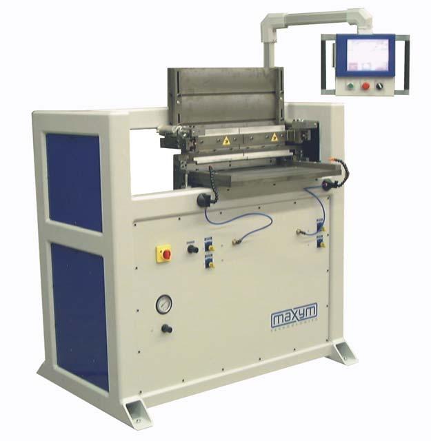
3 Visual Tour Front View Touch Screen Blow Off Control Power Switch Air Pressure Control Air Clamp Controls Stop Button Start Cycle Button Top Table Air Clamp Controls Bottom Table Air Clamp Controls Rear View 5 hp Tool Change Spindle Pneumatic Controls (located behind panel) Air Inlet Electrical Cabinet 3

4 Cutter, Backstop Fence and Tool Release Button Backstop Fence Tool Release Button Cutter 4
5 Introduction The Maxym Dovetailer can create both blind and thru dovetails. Both the blind and thru dovetails are comprised of two parts, the pins and the tails. The pin is the male portion and the tail is the female. (see below) In the blind dovetail, the pins do not cut all the way through the stock, leaving the joint visible from only one side. Hence the term Blind Dovetail or sometime referred to as a Half Blind Dovetail. With the Maxym Dovertailer, the operator inputs the position and size of the pins and the dovetailer can cut both the pins and the tails. In the case of the blind joint, both halves are cut with the same cutter and can be placed in the machine for cutting in one cycle. Blind Dovetails Thru Dovetails Pins Tails Pins Tails 5

6 Operating the Maxym Dovetailer Starting the Dovetailer Once power is applied, the dovetailer spindle moves to the start position on the righthand side of the machine with the cutter below the horizontal table and the fence will move up to the ready position. CAUTION! The air clamps may extend briefly when power is applied. Using Your Touch Screen Touch Screen Start Button Stop Button Air Clamp Controls The touch screen is combined with a computer screen to create artificial buttons. This allows the computer to create a variety of functions in one location. To operate it, simply touch the item you would like to select or change. The touch screen is made of a flexible membrane over a glass. When you touch the screen, you bend the membrane to make contact with the glass. The computer can then read the location of your touch. It is best to use your finger to touch the screen. You should never use a sharp or hard object! This will puncher or dimple the flexible membrane. There are three types of entries you can make on the touch screen; Buttons Numbers Text Buttons can take a verity of shapes and might not look like a raised buttons. The buttons that look raised have an active and inactive shape. Inactive, Raised and darkened Active, Sunken and lightened 6


7 Numbers that are drawn with dimension line can be changed by touching the number. When you touch the number a keypad will appear. Type in your new dimension by touching the numbers on the keypad. If you make a mistake the < key is a Backspace to delete the last entry. The numbers you type will appear in a box on the number you touched. Once you have finished typing touch ENTER. You can cancel the touch pad completely by touching ESC. Dimension Line Touched Dimension Decimal Point Keypad ESC Key When text entry is required an alphanumeric keypad will appear. Type the text by touching the letters and symbols on the keypad. Like the numeric keypad the < is used to backspace any errors. Touch ENTER to finish and ESC to cancel except for NOTES. When entering notes the ENTER key will start a new line and the ESC will finish. ENTER Key BACKSPACE Key ESC Key 7

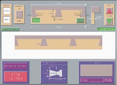
8 The dovetail screen is broken in to three sections. The top third of the screen is where you enter your dovetail joint specifications. The center of the screen displays what your dovetail joint will look like. The lower third are control functions such as machine settings and file access for saving and loading dovetail joint setups. The center dovetail display will change every time you change a dimension on the dovetail specifications. The dovetail specification section will not change shape. Dovetail Joint Specification Dovetail Joint Display Machine and File Controls 8


9 Preparing your dovetail Tools Before entering dimension on the touch screen, you will need to collect measurements from your dovetailed parts. Before you setup your dovetail dimensions, your Maxym dovetailer will need to know the type of cutters you will be using. You can enter up to ten different cutters in the tool table. Once the tool table is complete, you should select the tool you will be using before you setup your dovetail joint. By doing so, this will insure that your proper limitation on your pin sizing and also, your joint will be displayed properly. To select a tool touch anywhere on the tool diagram at the bottom of the touch screen. Then select a tool from the tool table. If the tool you need is not on the table, see the Dovetailer Installation and Maintenance Manual for details on entering a new tool. Tool Table Cutter Diagram Once you have selected a tool, you will be warned to insert the tool into the Dovetailer. Be sure to change the cutter because operating the machine with the wrong cutter selection will damage the machine and/or cutter! 9

10 Changing the Cutter To change the cutter you hold on to the tool and then press on the Tool Release Button as shown below. Tool Release Button Cutter 10
11 Setting Your Dovetail Dimensions Once you setup your tool table you can now describe your dovetail joint. This is done by changing the dimensions on the dovetail specification screen. On the Maxym Dovetailer you will be entering dimensions for the pins. The tails always match the pins. Here are the dimensions you will need to describe your joint. Stock Width Stock Thickness Pin Offset (fence Side) Pin Offset Pin Height Pin Width Number of Pins Stock Width The stock width is for the pinned panel. The Pin Offset on the fence side will be accurate but the Pin Offset on the opposite side will depend on the accuracy of the stock width. Stock Width Stock Width Stock Thickness Stock Thickness Stock Thickness The stock thickness determines the depth of the pin and tail on a blind joint, so the stock thickness does not have to be the actual thickness. With a thru joint, the stock thickness is the length of the pin and if the pin is to match the stock they must be the same. Stock Thickness Stock Thickness Blind Joint Thru Joint. 11
12 Pin Height The pin height is measured from opposite sides for the blind and thru pins. With the blind pin the reference surface is the inside of the pinned panel and the pin height represents how far the pin will protrude in the panel s thickness. The excess thickness makes up the blind front. Blind Pin Excess Stock Pin Height Reference Edge With thru pins, the reference edge is the back or outside of the panel. This insures that the back or outside of the pin is flush. The excess stock is inside behind the tail and is not visible. Pin Height Reference Edge Excess Stock The maximum pin height will be restricted to the length of the tool currently selected. 12
13 Number of Pins and Pin Offset The Maxym Dovetailer will automatically enter the number of pins when you enter the stock width, you can then use the Number of Pins Button to change it if needed. You must have a minimum of two pins. These pins are measured from the edge of the stock to the inside edge of the pins. With blind dovetails traditionally the first pins on the edge of the stock are partial or half pins. The half pins are counted as full pins when setting the Number of Pins. Pin Offset Pin Offset Half Pin 4 Pins 4 Pins The remaining distance between the inside of the first two pins is divided evenly for any remaining pins Pin Width The pin width can be greater than the diameter of the cutter. The Maxym dovetailer will automatically make extra passes to widen the tail opening. If the first two pins are half pins, the width of the half pin will not exceed the Pin Offset for it s respective side. The pin cannot be smaller than the tool diameter. Unused Half Pin Pin Width 13
14 Fit & Spoil on/off A dovetail tool will cut a different size hole in different stock, such as hard wood verses softwood or variations in moister content. The result is that with the same machine settings you can get a different fit or tightness of the joint. The Fit allows you to vary the size of the pin without changing the resulting tail. The amount of fit is relative to the Pin Width. This will have the affect of tightening or loosening the joint. If you save the setting for a particular joint, the fit is saved with it. That way, you can have different files for different types of stock. The Spoil on/off button is used to tell the dovetailer if you have a spoil board under your part on the lower table. The spoil board setting is on the Machine Setup menu. See page 21 for an explanation of the spoil board setting. Preparing To Cut Your Stock The Maxym Dovetailer has four cutting locations and each location has three reference edges. These reference edges are the table, the side fence and the insert fence. Side Fence HI LEFT Upper Table HI RIGHT LO LEFT Lower Table LO RIGHT Side Fence Insert Fence As mentioned earlier in Setting Your Dovetail Dimension, your joint also has reference edges. To ensure that the exposed parts of the joint are a good fit, the reference edges should be placed against a fence or table. For example, we will cut a draw box with a blind joint on the front and thru joint on the rear. We will assume that the bottom of the box wants to have smooth fit on all the joints. We will call the bottom our reference edge. For this example, three of the sides will be cut using a dovetail tool and the rear will use a straight cutter for the thru pins. 14
15 Left Front Left Rear Front Right Front Right Rear Thru Joint Blind Joint Reference Edge Cutting the Blind Joint First we will cut the front or blind joint first. The Upper Table is only used for blind pins, which is our front panel. The Lower Table is used for all the tails and the thru pins. Since the front and sides are cut with the same tool and the blind pins (our front) uses the upper table, we can cut both pieces at the same time. The sides (blind tails) will be placed on the lower table with the outside facing down and the front (blind pins) will be placed on the upper table with the inside facing the table. Previously cut Right Side Joint Draw Front with outside Out Joint Left Side with inside Up Joint Draw Front with ouside Out Joint Right Side with inside Up Joint To tell the Maxym Dovetailer to cut a blind joint, touch the Blind joint type button. You also use the Panel buttons Pins, Tails to select which half of the joint you will be cutting. With a blind joint both the Pins and Tail buttons can be on at the same time. Panel Buttons Joint Type Buttons 15


16 To tell the Maxym Dovetailer which position the part will be placed in we will use the Left Side, Right Side buttons. These buttons are for the lower table only. The upper table is only used for blind pins and it s position is always opposite of the lower table. Position Buttons Always check the to the tool description at the bottom of the touch screen with the actual tool in the dovetailer before proceeding! Clamping the Stock Once the stock is in it proper location, close the appropriate clamps. The upper clamps can only be operated manually and are not affected by the HAND/AUTO selector. Upper Left Clamp Upper Right Clamp Lower Left Clamp Lower Right Clamp Upper Left Clamp Control Upper Right Clamp Control Blow Off Control Lower Left Clamp Control Lower Right Clamp Control HAND/AUTO Selector The lower clamps can be set to operate when the START button is pushed by placing the HAND/AUTO selector in the AUTO position and placing the Lower Clamp Controls in the CLOSE position. Once everything is in place and clamped, just push the green START button below the touch screen. 16
17 Cutting the Thru Joint Now we will cut the thru joints at the back of the draw. First you will touch the Thru button then selecting the proper cutter from the tool table. Next, set the proper dimensions for your thru joint. Since, the pins for the thru joint will require a tool change, we will cut the tails first. This is done by, touching TAILS at the panel selection buttons. These parts will be cut on the bottom table. With a thru tail the cutter moves completely thru the stock so either side can be placed down against the table. The cutter will move thru from top to bottom so the upper surface will have the cleanest edge if you are not using a spoil board. If you want the best side out then the right side will be cut on the right fence. Place the stock at the proper location and select the side being used with the position buttons. Clamp the stock and START the cycle. Again, make sure the proper tool in the dovertailer! Previously cut blind joint Left Side with outside Up Joint Right Side with outside Up Joint Previously cut blind tail To cut pins touch the Pins buttons on the Panel Selection buttons. Next, you will need to select a straight cutter from the tool table (See Preparing your Dovetailer Tools). The Maxym dovetailer stores a separate cutter for the pins and tails. So make sure you have the proper half of the joint selected before choosing a tool. This will also insure the any joint you save will have a tool for both parts. (See Save Current Settings) 17
18 The thru pin is cut with the narrow part of the pin (the outside of the panel) on the table. This insures that the pin is flush to the end of the side panel. If the reference edge is on the bottom of the draw this places the back right corner against the right fence. Left Front Left Rear Front Right Front Right Rear Reference Edge Back Panel, Outside Down Left Joint Back Panel, Outside Down Right Joint You know the drill! Clamp it and Cut it! 18

19 Dovetail Setup Notes The notes window allows you to type in notes to explain your setup. You might want to describe the stock you are cutting using the current settings. Or you can explain some of your manual settings. To enter notes, touch the window below the word 'NOTES'. You will be asked to clear the note window. If you want to add to your existing notes, touch 'NO'. If you want to start new notes, touch 'YES'. A keyboard will appear over the dovetail display window and a cursor will appear in the note window. You can type in letters using the keyboard. If you make a mistake, use the back space ('<') to delete it. When you are finished typing, touch the escape key ('ESC') to end note entry. 19

20 File Menu The settings you have entered for your dovetail will stay in the touch screen until you change it, even if the dovetailer is powered off. When the dovetailer is turned on it will have the last setting and will update the cutter computer automatically. If you change the dimensions but would like to return to some previous settings, you can save your current settings and load previous settings from the 'File Menu'. Touch the word 'FILE' at the lower right corner of the screen to open the File Menu. The File Menu is comprised of two main windows, the File Name Window and the Directory Name Window. The File Name Window shows the name of the currently saved dovetail setup. Below this window is the Directory Selection Button. The name of the directory that the files are in appears on this button. A directory is like a folder used to group like files together. If there is only a '\' on the Directory Selection Button, you are in the Main or Root directory. Below the Directory Selection Button is the Directory Name Window. This is a list of other directories or folders that are on the dovetailer. To open a directory, touch the directory name in the window and then touch the Directory Selection Button. The File Name Window then shows only the file(s) in that directory. The Directory Name Window will also change to only the directory in this directory. Like having a file folder in a file folder. To go back to a the previous directory, touch the Directory Selection Button before touching a directory name and it will jump back to the previous directory. If you would like to make a directory to save setups in, touch the Make Directory button and type in a name for your directory. You can only use eight letters for directory or file names. 20

21 The file names can be sorted alphabetically (NAME) or by date (TIME) with the most recent file at the top. This is done by pressing the Sort Name button at the top left of the File Name Window. The File Name Type button at the top right of the File Name Window allows you to select the two types of files that show on the File Name Window. DOVETAIL files are the dovetails setups. This is the type you will be using the most. You can also list PATTERN files. These files are created with our Advanced Programming Option, Pattern files can only be loaded. Save Current Settings To save your current settings, touch the 'SAVE' button on the file menu. A box will appear with the words 'Save As =' in it. Also, a keyboard will appear to allow you to type in a name for your settings. As you type, the name will appear in the 'Save As' box. You are limited to eight letters for your name. If you want to change the name in the box, touch the '<' key, to delete the letters. Once you have typed in the name, touch the 'ENTER' button and the setting will be saved. The setting name will appear in the window above the dovetail display. All of the dovetail dimensions are saved with the settings. The tool table and calibration setting are not saved with the dovetail settings. Those setting are machine related and are stored separately. 21
22 Load Saved Settings To load a saved setting, simply touch the name in the File Name Window, then touch the Load button. If the name does not appear, touch the file navigation buttons until the name appears in the window. Selecting a file name can serve other purposes. If you would like to save your settings over a previous file, select the file name before touching 'SAVE'. This will bring the name to the 'Save As' box. Then touch 'ENTER' to replace the old file. You will have to verify the file replacement. Also, if you are not sure which file you would like to load; selecting the file name will display the notes for that file in the notes windows. You can make a more informed selection with the extra information in the notes. Deleting Files and Directories To delete a file, you need to select the file in the File Name Window and then press the Delete Button. A prompt will appear showing the file and a Yes/No selection. If you would like to delete it hit Yes (if not, hit No). To delete a directory you must only select the directory name and not open it. Also, before you delete the directory, you must delete all files in that directory. 22

23 Machine Setup The machine setup window is opened by touching the machine setup button on the main screen. Cutting Speed Calibrations Tool Table Spoil Board Units Blind Pin Cut Cutter Diagram Calibrations The Maxym Dovetailer is calibrated at the factory prior to shipping. These settings are saved in a permanent file on the Dovetailer. It is recommended that you cut and measure a test dovetail to ensure that the machine is calibrated. See the Maxym Dovetailer Installation and Maintenance Manual on how to calibrate the machine. Cutting Speed Cutting speed is the speed at which the cutter moves through the wood. Faster cutting speeds allow higher production rates, but may chip the wood or overload the cutter. The cutting speed is control by sliding the white cutter speed bar. The maximum speed is 400 inches per minute (ipm). The cutter travels at the maximum speed when moving between cuts. The cutting speed is saved with the dovetail files. The tool table and calibration settings are machine dependent and are automatically saved in a separate machine setup file. Spoil Board When the dovetail cutter exits the bottom of the stock the advancing cutter can cause chipping. Placing a spoil board under your stock can prevent this. The spoil board raises the stock above the table, so the spoil board setting is used to tell the Maxym Dovetailer how thick your board is. Touch the dimension on the Spoil Board button to enter your new thickness. 23
24 Blind Pin Cut This button is used to select how aggressively the cutter will enter the end of the upper stock when doing blind pins. You can ether select Cutter Diameter or Cutter Radius. With Cutter Diameter the cutter will cut the full diameter until the correct depth is reached. If the Stock Thickness is set less than or equal to the cutter diameter, it will cut it in one pass. If the Stock Thickness is set greater than the cutter diameter, the dovetailer will repeat the cut until the correct depth is reached. With the setting on Cutter Radius, each pass will take only half of the cutter diameter. Again, the number of passes will depend on the Stock Thickness setting. Units This button is used to select the units for data entry. English units are inches and can be entered to three decimal places. The metric units are millimeters and are two decimal places. When using metric units, there can be a rounding down of the second decimal place because of the English screws. Tool Table The Maxym Dovetailer can save up to ten tools to be used to create your dovetail joints. See Preparing your Dovetail Tools in the Installation & Maintenance Manual. 24

25 25
MAXYM Mortiser Operating Manual
 MAXYM Mortiser Operating Manual Rev 2.112/16/02 Copyright MAXYM Technologies Inc. Table of Contents Visual Tour 1-2 Operating the Maxym Mortiser 3 Starting the Mortiser 3 Touch Screen Description 3 Mortise
86N80.10 Economy Dovetail Jig
 86N80.10 Economy Dovetail Jig IMPORTANT: Before using your dovetail jig, it should be securely fastened to a workbench. For a temporary setup, attach the jig to a piece of ¾ thick plywood or MDF long and
Woodline USA Woodline Spacer Fence System
 Woodline USA Woodline Spacer Fence System MADE IN THE USA Includes: (1) ¼ Spacer Fence (1) 3/8 Spacer Fence (1) ½ Spacer Fence (1) Hardware Package (1) 3 Piece Brass bar set (2) Setup Blocks Visit Us Online
Complete Dovetail Jig Instructions
 Complete Dovetail Jig Instructions 15 18 4 3 1 12 13 8 19 17 16 6 14 5 9 11 10 2 9 PARTS LIST - Complete Dovetail Jig Introduction Your new dovetail jig will cut Full Through Dovetails and three varieties
Finding Offsets for Multiple Spindles/Air Drills
 888-680-4466 ShopBotTools.com Finding Offsets for Multiple Spindles/Air Drills Copyright 2016 ShopBot Tools, Inc. page 1 Copyright 2016 ShopBot Tools, Inc. page 2 Introduction This document explains how
Table of Contents. Table of Contents. Preface 11 Prerequisites... 12
 Table of Contents Preface 11 Prerequisites... 12 Basic machining practice experience... 12 Controls covered... 12 Limitations... 13 The need for hands -on practice... 13 Instruction method... 13 Scope...
Copyright 2007 MLCS 1
 Copyright 2007 MLCS 1 REFERENCE GUIDE and SPECIFICATIONS: Edge Guides: This 12 Dovetail Template comes complete with 2 Edge Guide Sets one set for Half Blind and one set for Rabbeted Half Blind Dovetails.
MODEL SETUP & OPERATION MANUAL DOVETAIL JIG FEATURES SPECIFICATIONS
 SETUP & OPERATION MANUAL FEATURES Male and female dovetail joints are cut simultaneously, to ensure perfectly matched dovetail joints. Side stops provided, allow repeated precise dovetail joint cutting
Dozuki. Written By: Dozuki System. Guide to calibrating the Haas wireless intuitive probing system. How to Calibrate WIPS
 Dozuki How to Calibrate WIPS Guide to calibrating the Haas wireless intuitive probing system. Written By: Dozuki System 2017 www.dozuki.com Page 1 of 22 INTRODUCTION Getting Started On initial setup or
Pro-Doweling Kit USER S MANUAL #840. Visit us at
 Pro-Doweling Kit USER S MANUAL #840 99 Washington Street Melrose, MA 02176 Phone 781-665-1400 Toll Free 1-800-517-8431 Visit us at www.testequipmentdepot.com Please read this manual carefully and thoroughly
DISCO DICING SAW SOP. April 2014 INTRODUCTION
 DISCO DICING SAW SOP April 2014 INTRODUCTION The DISCO Dicing saw is an essential piece of equipment that allows cleanroom users to divide up their processed wafers into individual chips. The dicing saw
How to Calibrate a CNC Machine's Positioning System
 How to Calibrate a CNC Machine's Positioning System Guide to calibrating the Haas wireless intuitive probing system. Written By: Kim Payne 2018 gunnerautomotive.dozuki.com/ Page 1 of 20 INTRODUCTION Attention:
Z-Truck Up-and-Down Motion. Y-Truck Side-to-Side Motion. Head. Squaring Plate. Sliding Plate FIGURE 1: THE CARVEWRIGHT MACHINE
 Setup and use of CarveWright CO2 Powered Dragster Jig The CO 2 powered Dragster Jig will arrive from the factory fully assembled, calibrated, and squared. In order to get the best results, your CarveWright
Figure 1: NC EDM menu
 Click To See: How to Use Online Documents SURFCAM Online Documents 685)&$0Ã5HIHUHQFHÃ0DQXDO 6 :,5(('0 6.1 INTRODUCTION SURFCAM s Wire EDM mode is used to produce toolpaths for 2 Axis and 4 Axis EDM machines.
Index. Page (s) 1 4. Features
 1 4. Features") Instruction Manual Index Features Page (s) 1 4 LCD Monitor Load Design USB & USB Disk Drive Design Rotation/Scaling Thread Break Detect Work Sequence Frame protection Auto Origin Return Idle (Float) Mode
Instruction Manual Index Features Page (s) 1 4 LCD Monitor Load Design USB & USB Disk Drive Design Rotation/Scaling Thread Break Detect Work Sequence Frame protection Auto Origin Return Idle (Float) Mode
WARNING: Read these instructions before using the machine DOVETAIL JIG MODEL NO: CDTJ12 / CDTJ24 PART NO: ,
 WARNING: Read these instructions before using the machine DOVETAIL JIG MODEL NO: CDTJ12 / CDTJ24 PART NO: 6462170, 6462175 OPERATION & MAINTENANCE INSTRUCTIONS LS0111 INTRODUCTION Thank you for purchasing
Mount to the Wall INSTALLATION MANUAL
 Mount to the Wall 15 Locate the Wooden Studs This step applies to wooden stud wall installation only. Determine and mark the exact locations of two stud centers on the wall. Wooden studs should be spaced
MEASUREMENT CAMERA USER GUIDE
 How to use your Aven camera s imaging and measurement tools Part 1 of this guide identifies software icons for on-screen functions, camera settings and measurement tools. Part 2 provides step-by-step operating
Extendable Large Dovetail Jig
 Extendable Large Dovetail Jig Instruction Manual Part # 3458 CAUTION: Please read, understand, and follow all manufacturers instructions, guidelines and owners manuals that come with your power tools.
Band-Master ATS Nano Pneumatic Banding Tool Operating Instructions
 Band-Master ATS 601-118 Nano Pneumatic Banding Tool CONTENTS 601-118 Overview... 3 Safety.... 5 Initial Tool Set-up... 5 Regulator assembly mounting... 5 Attach tool head to regulator.... 6 Operating instructions...
15 Dovetail Jig. Instruction Manual. Part # 3452
 15 Dovetail Jig Instruction Manual Part # 3452 CAUTION: Please read, understand, and follow all manufacturers instructions, guidelines and owners manuals that come with your power tools. Peachtree Woodworking
ClearSpan PolyMax Windbreak Wall
 ClearSpan PolyMax Windbreak Wall Photo may show a different but similar model. 2007 ClearSpan All Rights Reserved. Reproduction is prohibited without permission. Revision date: February 2007ldg STK# DIMENSIONS
SHUR-LOK CORPORATION TECHNICAL SALES BULLETIN
 Page 1 of 11 1.0 INTRODUCTION: 1.1 This Technical Sales Bulletin describes installation procedure of SL850 Blind-Threaded and SL854 Thru-Threaded Pull-up type inserts. These procedures use the SLPGA850
Setting Part Zero and Setting Cutting Tool for Wheel Lathe
 There are three sections in this document: A: Setting Tool #1 and Tool #2 on center line height to the spindle which are explained in steps 1 thru 3 B: Setting Part 0 for X & Z and setting X & Z reference
Nancy s Knit Knacks LLC 4 Yard Option Upgrade Kit Assembly Instructions and User Manual
 Nancy s Knit Knacks LLC 4 Yard Option Upgrade Kit Assembly Instructions and User Manual Thank you for purchasing our 4 Yard Option (4YO) Upgrade Kit. To install this upgrade you are simply going to assemble
FINGER JOINT TEMPLATES LEIGH DEDICATED CUSTOMER SUPPORT Using the F3, F18 and F24 Finger Joint Templates on Leigh D-Series & SuperJigs
 LEIGH FINGER JOINT TEMPLATES Using the F, F and F Finger Joint Templates on Leigh D-Series & SuperJigs DEDICATED CUSTOMER SUPPORT -00-- ii Introduction F, F & F FINGER JOINT TEMPLATES USERGUIDE FOREWORD
Operating, Servicing, and Safety Manual Model # & 72 Ultimate Box & Pan Brake
 Operating, Servicing, and Safety Manual Model # 2800 48 & 72 Ultimate Box & Pan Brake CAUTION: Read and Understand These Operating, Servicing, and Safety Instructions, Before Using This Machine. 1-800-467-2464
VACUSEAL MODEL 200. HOT TUB PRODUCTS 233 Carrington Road Bethany CT
 VACUSEAL MODEL 200 J G F G H L HOT TUB PRODUCTS 233 Carrington Road Bethany CT 06524 860-469-2580 www.vacusealcoverlift.com www.hottubproducts.com Made in USA H K E D C I A P B 10 9 8 7 6 5 4 3 2 1 0 SPAS
Precision Steel Car s 100 T Steel Coil Car
 Precision Steel Car s 100 T Steel Coil Car Precision Steel Car www.precisionsteelcar.com info@precisionsteelcar.com Paul Vernon: (513) 571-5739 Revised 4/30/2009 Contents of Kit Main Tube Side Frame 2
Print Head Installation Guide
 Print Head Installation Guide MCS Raptor 6 (MCS Eagle AMS Software) is copyright of MCS Incorporated. 2015 MCS Incorporated. 1 Contents Tools... 4 Warnings... 4 Introduction... 4 Section One - Pillar Installation...
Gared Pro-S Portable Backstop
 Models: 9616 & 9618 Installation, Operation and Maintenance Instructions Please read all instructions before attempting installation or operation of these units SAVE THESE INSTRUCTIONS FOR FUTURE USE PUBLICATION
Problem/Procedure Description. Requirements. Problem/Procedure Solution. How-To Document. Updated on: 11/13/2008 By:Christopher Ware
 Problem/Procedure Description Performing maintenance on 95s, 95sII and H100 Requirements Ball Bearing Grease (LPKF P/N 106976) Tri-Flow Teflon lubricant aerosol. 3-in-1 Multi-purpose Oil Electronic Component
Fig2: The Sliding Glue Block from the back.
 Ornament Stand Introduction It was one of those forehead smacking moments. I was taking the #2 jaws off my Stronghold chuck, to put on my homemade wooden two jaw chuck set-up. For some reason instead of
Model D1700/D1701 Moulding Head Instruction Sheet
 Model D1700/D1701 Moulding Head Instruction Sheet Phone #: (360) 734-3482 Online Tech Support: tech-support@shopfox.biz Web: www.shopfox.biz To reduce risk of serious personal injury when using moulding
OPERATOR'S MANUAL RULES FOR SAFE OPERATION
 OPERATOR'S MANUAL #4950300 ROUTER AND JIG SAW MOUNTING KIT (FOR USE WITH THE BT3000 TABLE SAW) CONGRATULATIONS AND THANK YOU FOR BUYING THIS RYOBI ROUTER AND JIG SAW MOUNTING KIT. Your new #4950300 Router
CNC Chucker Lathe P/N 6600, 6610, and 6620
 WEAR YOUR SAFETY GLASSES FORESIGHT IS BETTER THAN NO SIGHT READ INSTRUCTIONS BEFORE OPERATING PRODUCT DESCRIPTION 6600 CNC Chucker w/3c headstock, ball screws, high-torque stepper motors & PC w/4-axis
CS 4095 Ultra. Technical and User Manual
 CS 4095 Ultra Technical and User Manual V4 02/2002 MANUAL MODE Your CS4095 can work on 3 different manual modes: MINIMUM (manual) : the foot pedal pushed, the complete joining cy,cle is carried out by
PORTABLE ADJUSTABLE BASKETBALL SYSTEM
 Instruction Manual PORTABLE ADJUSTABLE BASKETBALL SYSTEM P A R T S L I S T 5 1/2 and 8 safe play clearance Item Qty Description Item Qty Description A 1 Portable Base Assembly M 4 1/2 Lock Nut B 2 Front
Conversational CAM Manual
 Legacy Woodworking Machinery CNC Turning & Milling Machines Conversational CAM Manual Legacy Woodworking Machinery 435 W. 1000 N. Springville, UT 84663 2 Content Conversational CAM Conversational CAM overview...
JointCAM Reference Guide. JointCAM. Reference Guide. Version 1.05 Copyright G-Force CNC, LLC, All Rights Reserved.
 JointCAM Reference Guide JointCAM Reference Guide Version 1.05 Copyright G-Force CNC, LLC, 2014-2018. All Rights Reserved. 1 of 50 JointCAM Reference Guide Disclaimer All CNC machines are potentially dangerous.
Single Pass Half-Blind Dovetails
 9 DR Pro - CHAPTER Single Pass Half-Blind Dovetails Why rout single pass dovetails on a variable spaced Leigh jig? Well, you just may need to reproduce or restore a late 9th or early 0th century drawer
S A F T E Y W A R N I N G
 BINDING CUTTING BASE This tool is designed to fit on a Porter Cable Model 310 and 3701 trim router, this combination will provide you with an easy way to accurately cut a binding rabbet on you instrument.
INSTRUCTION MANUAL. Force Transducer Output Tube Repair Kit
 INSTRUCTION MANUAL Model 400-TR Force Transducer Output Tube Repair Kit June 4, 2004, Revision 5 Copyright 2004 Aurora Scientific Inc. Aurora Scientific Inc. 360 Industrial Pkwy. S., Unit 4 Aurora, Ontario,
# in 1 Metal Worker Auxiliary Operating Instructions
 340 Snyder Avenue, Berkeley Heights, NJ 07922 www.micromark.com MMTechService@micromark.com Tech Support: 908-464-1094, weekdays, 1pm to 5 pm ET #86556 3 in 1 Metal Worker Auxiliary Operating Instructions
790XL Dado Jig Owners Manual Please Read Carefully!
 790XL Dado Jig Owners Manual Please Read Carefully! 790XL Dado Jig Hardware List: Identify and verify that you have all of the hardware shown below prior to assembly. Tools needed for assembly: #2 & 3
CHAPTER 10. Half-Blind Dovetail Procedures
 CHAPTER 0 Half-Blind Dovetail Procedures 6 Chapter 0 D User Guide HALF-BLIND DOVETAIL PROCEDURES Chapter Foreword In these instructions for using the Leigh Dovetail Jig, we have recommended using certain
MODEL SETUP & OPERATION MANUAL DOVETAIL JIG FEATURES
 SETUP & OPERATION MANUAL FEATURES New clamping system for greater accuracy. Lockable template height for a stable platform for the router. Cuts precision matching dovetails with the same accuracy found
Dovetail Saw Guides. Figure 1: Dovetail saw guide, exploded view. Guide Block. UHMW Friction Pad. Sliding Clamp. Rare-Earth Magnet
 Dovetail Saw Guides U.S. Pat. No. 6,607,016 Dovetail joints have traditionally been the hallmark of a cabinetmaker who had acquired an expert level of skill. They are also a mark of quality and attention
V4 Premium Kit. Prusa i3 Build Guide
 V4 Premium Kit Prusa i3 Build Guide Hi! Congratulations on your purchase of the DIYElectronics.co.za Prusa I3 kit, the best South African 3D Printer Kit! Hopefully this should serve as complete guide to
Butterfly Leaf Dining Table Plans
 Butterfly Leaf Dining Table Plans Part 1 An attractive dining table with a secret: the leaf folds and stores inside the table. Season 1, Episode 7 P a g e 2 I first saw a butterfly leaf table in a back
Printing for Professionals
 Océ cm550 Printing for Professionals User s Guide Enlarge Display Operations Introduction Introduction Thank you for choosing this machine. The cm550 User s Guide [Enlarge Display Operations] contains
Innov-ís 2500D PREMIUM PACKAGE
 Innov-ís 2500D PREMIUM PACKAGE Version 2 Upgrade Kit Operation Manual Before using this upgrade kit, be sure to read this Operation Manual for information on its correct use. CONTENTS Before You Start...
788XL Dado Jig Owners Manual Please Read Carefully!
 788XL Dado Jig Owners Manual Please Read Carefully! 788XL Dado Jig Hardware List: Identify and verify that you have all of the hardware shown below prior to assembly. Tools needed for assembly: #2 & 3
GROUND BALANCE & PINPOINT BUTTON MODIFICATION By Sven Stau October 2008
 TESORO CIBOLA GROUND BALANCE & PINPOINT BUTTON MODIFICATION By Sven Stau October 2008 Get some added performance by replacing the internal factory fixed GB with an external user friendly, fully adjustable
How to install backchecks
 How to install backchecks Note: All pictures can be enlarged for better clarification. Revision 7 8/2009 Backchecks wear out in a piano much like brake pads in an automobile. While wear is a valid reason
INSTALLATION INSTRUCTIONS
 INSTALLATION INSTRUCTIONS TM X-10 Type 1F HIGH SECURITY ELECTRONIC LOCK Table of Contents Introduction... 1 Basic Tools and Materials Needed... 1 Lock Parts for Installation... 1 Installation Kit Contents...
Wixey ELECTRONIC DIGITAL READOUT
 Wixey ELECTRONIC DIGITAL READOUT Model WR500 INSTRUCTIONS Step 1- Mounting the readout assembly to your planer 1 Tighten any of the side cover mounting screws (1) and if necessary use a small amount of
PRAZI USA. Model PR-3900 Owners Manual. Please read this manual in its entirety before using the PRAZI ChestMate.
 PRAZI USA Model PR-3900 Owners Manual Please read this manual in its entirety before using the PRAZI ChestMate. PRAZI USA 214 Rear South Meadow Rd (800)-262-0211 Plymouth MA, 02360 www.praziusa.com ChestMate
INSTRUCTIONS FOR ASSEMBLING YOUR CLEARMOUNT MITER SAW SCALE
 INSTRUCTIONS FOR ASSEMBLING YOUR CLEARMOUNT MITER SAW SCALE Pictures shown are our SW7 but these instructions apply to all of our scales. Special information for other models is noted. ** Read & Follow
Operating, Servicing, and Safety Manual Model # 100 Standard Hydraulic Tubing Notcher Model #100-U Heavy Duty Hydraulic Tubing Notcher
 Operating, Servicing, and Safety Manual Model # 100 Standard Hydraulic Tubing Notcher Model #100-U Heavy Duty Hydraulic Tubing Notcher Model # 100 Standard Model #100-U Heavy Duty CAUTION: Read and Understand
Installing a 3 Indexer: Desktop Tools
 888-680-4466 ShopBotTools.com Installing a 3 Indexer: Desktop Tools built after October, 2012 Copyright 2016 ShopBot Tools, Inc. page 1 Copyright 2016 ShopBot Tools, Inc. page 2 Table of Contents Overview...5
Agricultural Mechanics and Technology Power Tool Safety Rules
 Agricultural Mechanics and Technology Power Tool Safety Rules Name: BAND SAW Use: Cutting curves, circles and irregular shapes. 1. Use clean SHARP blades. 2. The teeth should always point DOWN. 3. Adjust
400A 40113V, 401A 40120V, & 401AL 40120VL ALUMINUM VERTICAL 4000 LB LIFT INCLUDES SCREW LEG ASSEMBLY INSTRUCTIONS
 12/11/07 PAGE 1 OF 12 400A 40113V, 401A 40120V, & 401AL 40120VL ALUMINUM VERTICAL 4000 LB LIFT INCLUDES SCREW LEG ASSEMBLY INSTRUCTIONS Thank you for purchasing our product! *Please read these instructions
CHAPTER 8. Through Dovetail Procedures
 CHAPTER Through Dovetail Procedures 52 Chapter D4 User Guide THROUGH DOVETAIL PROCEDURES Chapter Foreword In these instructions for using the Leigh Dovetail Jig, we have recommended using certain cutters
U.S. Rack, Inc Falcon Drive, Madera, CA APR17 INSTALLATION AND USE INSTRUCTIONS for SIDE-MOUNT LADDER RACK
 U.S. Rack, Inc. 2850 Falcon Drive, Madera, CA 93637 15APR17 INSTALLATION AND USE INSTRUCTIONS for SIDE-MOUNT LADDER RACK WARNING: Do NOT attempt to install or use this rack without following all instructions.
a.k.a. casegoods instructions
 a.k.a. casegoods instructions a a.k.a. workwall installation IMPORTANT NOTES Failure to install product according to installation instruction will result in loss of warranty. Tools required for assembly
Charles Neil Dovetail Jig Instructions
 Charles Neil Dovetail Jig Instructions Thank you for purchasing the Charles Neil (CN) Dovetail Jig. This is an easy to use and flexible jig for cutting through dovetails. These instructions complement
General Wood Shop Notes
 General Wood Shop Notes Restricted Materials No METAL or BONE of any kind on any machine or in the room o See additional restrictions individual machine All reclaimed and other than new lumber must be
CHAPTER 11 3/4" Box (Finger) Joints
 Joints") 53 RTJ400 OPERTION CHPTER 11 3/4" ox (Finger) Joints IMPORTNT SFETY NOTE efore using your Leigh RTJ400 you must have completed the preparatory steps listed in the previous pages, including reading the
53 RTJ400 OPERTION CHPTER 11 3/4" ox (Finger) Joints IMPORTNT SFETY NOTE efore using your Leigh RTJ400 you must have completed the preparatory steps listed in the previous pages, including reading the
6000 Horizontal Router Table Owners Manual Please Read Carefully!
 6 Horizontal Router Table Owners Manual Please Read Carefully! Parts List Please identify and verify that you have all of the hardware & parts shown prior to assembly. The parts described in this box are
IFU Page 1 Worktop Jig 700 & 900 Instructions Leaflet
 IFU 049.2 Page 1 Worktop Jig 700 & 900 Instructions Leaflet WORKTOP JIG 700 FOR RIGHT AND LEFT STANDARD 90 AND 45 JOINTS FOR RECESSES FOR WORKTOP CONNECTING BOLT CUTS WORKTOPS FROM 400MM TO 700MM WIDE
End-On-End Dovetails D4R - CHAPTER 12
 D4R - CHAPTER End-On-End Dovetails 4 While you have the router set up for half-blind dovetails, it is a good time to try end-on-end dovetails. If you have not yet routed half-blind dovetails or read through
1. Turn off or disconnect power to unit (machine). 2. Push IN the release bar on the quick change base plate. Locking latch will pivot downward.
. 2. Push IN the release bar on the quick change base plate. Locking latch will pivot downward.") Figure 1 Miniature Quick Change Applicators, of the end feed type, are designed to crimp end feed strip terminals to prestripped wires. Each applicator is set up to accept the strip form of certain specific
Figure 1 Miniature Quick Change Applicators, of the end feed type, are designed to crimp end feed strip terminals to prestripped wires. Each applicator is set up to accept the strip form of certain specific
Half-Blind Isoloc Joint Procedures
 ISOLOC - CHAPTER 6 Half-Blind Isoloc Joint Procedures 6- Always use scrap boards to practice and test for fit. Rip the boards to width to suit the chosen template. The pin boards should not be less than
JointCAM Reference Guide. JointCAM. Reference Guide. Version 1.02 Copyright G-Force CNC, LLC, All Rights Reserved. 1 of 40
 JointCAM Reference Guide JointCAM Reference Guide Version 1.02 Copyright G-Force CNC, LLC, 2014. All Rights Reserved. 1 of 40 JointCAM Reference Guide Disclaimer All CNC machines are potentially dangerous.
DRILL GRINDING ATTACHMENT
 DRILL GRINDING ATTACHMENT To suit TM6025Q TOOL AND CUTTER GRINDER OPERATION S MANUAL 1 0º 270º 90º 180º INTRODUCTION Before grinding any cutters, you must set up the attachment to suit the type of cutter
LEG CURL IP-S1315 INSTALLATION INSTRUCTIONS
 LEG CURL IP-S35 INSTALLATION INSTRUCTIONS Copyright 2009. Star Trac by Unisen, Inc. All rights reserved, including those to reproduce this book or parts thereof in any form without first obtaining written
GATE INSTALLATION INSTRUCTIONS
 GATE INSTALLATION INSTRUCTIONS 1) Ensure posts for gate are fully installed. Posts need to be securely fastened to decking or concrete such that they will not sag with weight of the gate. For a single
ASSEMBLY INSTRUCTIONS FOR HAULER II SERVICE BODY A RACK
 ASSEMBLY INSTRUCTIONS FOR HAULER II SERVICE BODY A RACK T12USBA-1 shown above Package Contents: HARDWARE KIT PARTS (4) 3/8-16 x 3 CARRAIGE BOLTS (1) RAIL DRIVER S SIDE ASSEMBLY (20) 3/8-16 x 2 CARRAIGE
ROTARY DIE SLITTER MODEL RDS-100 OPERATING INSTRUCTIONS CHEMINSTRUMENTS 510 COMMERCIAL DRIVE FAIRFIELD, OHIO (513)
") ROTARY DIE SLITTER MODEL RDS-100 OPERATING INSTRUCTIONS CHEMINSTRUMENTS 510 COMMERCIAL DRIVE FAIRFIELD, OHIO 45014 (513) 860-1598 www.cheminstruments.com Revision 1.1 August 4, 2017 TABLE OF CONTENTS PRODUCT
ROTARY DIE SLITTER MODEL RDS-100 OPERATING INSTRUCTIONS CHEMINSTRUMENTS 510 COMMERCIAL DRIVE FAIRFIELD, OHIO 45014 (513) 860-1598 www.cheminstruments.com Revision 1.1 August 4, 2017 TABLE OF CONTENTS PRODUCT
LocoGear. Technical Bulletin - 14 November 28, 2003 Copyright 2003 by LocoGear LIVE STEAM CASTINGS. Tech Bulletin - 14
 LIVE STEAM CASTINGS LocoGear Tech Bulletin - 14 John D.L. Johnson 3879 Woods Walk Blvd Lake Worth, FL 33467-2359 jjohnson@locogear.com www.locogear.com Technical Bulletin - 14 November 28, 2003 Copyright
Grizzly Drill Press SOP
 Grizzly Drill Press SOP Drill Press is wired to run on 0V. Drill Press has a built in light with a ON/OFF switch. Never hold a workpiece by hand while drilling. Clamp it down or hold it in a vice. Never
Hydraulic Clamp Carrier. Installation & Operation Manual
 Hydraulic Clamp Carrier Installation & Operation Manual Hydraulic Clamp Carrier Installation & Operation Manual Quick Machinery Company 8272 Peninsula Drive Kelseyville, CA 95451 phone: (707) 272-6719
Tables it will work with
 What does it do? The Self Centering Vise is used to clamp and hold items that are normally to difficult to hold with a standard table clamp or double-sided engraving tape. It can be used to hold notary
Semi-concealed dovetail joints
 No. 100 Semi-concealed dovetail joints A Description The semi-concealed dovetail joint is a classic solid wood corner joint. It is suitable for joining wider slats, boards and solid wood panels. Semi-concealed
Getting Started. Terminology. CNC 1 Training
 CNC 1 Training Getting Started What You Need for This Training Program This manual 6 x 4 x 3 HDPE 8 3/8, two flute, bottom cutting end mill, 1 Length of Cut (LOC). #3 Center Drill 1/4 drill bit and drill
Copyright MLCS 1
 Copyright 2007. MLCS 1 WORKING WITH BOX JOINTS Box joints (AKA "Finger Joints") provide a simple, yet equally effective, alternative to dovetail joinery. In particular, they serve well for applications
MINI-LATHE QUICK CHANGE TOOL POST
 MINI-LATHE QUICK CHANGE TOOL POST Cutting and assembly details Machinists should familiarize themselves with the contents of this section before jumping in to the drawings. Many details are described here
DEUTSCH Instructional Manual for HDP-400 Power Crimper (TE CONNECTIVITY PN )
") ORIGINAL INSTRUCTIONS DEUTSCH Instructional Manual for HDP-400 Power Crimper (TE CONNECTIVITY PN 1606312-1) Instruction Sheet 0425-034-0000 15 JAN 18 Rev H NOTE All numerical values are in metric units
ORIGINAL INSTRUCTIONS DEUTSCH Instructional Manual for HDP-400 Power Crimper (TE CONNECTIVITY PN 1606312-1) Instruction Sheet 0425-034-0000 15 JAN 18 Rev H NOTE All numerical values are in metric units
GXCapture 8.1 Instruction Manual
 GT Vision image acquisition, managing and processing software GXCapture 8.1 Instruction Manual Contents of the Instruction Manual GXC is the shortened name used for GXCapture Square brackets are used to
SECTION side windows round corners
 03-701.00/ 1 SECTION 03-701.00 2011SE08 GENERAL DESCRIPTION The windows installed on Nova vehicles may be a onepiece fixed type, or may consist of an upper and lower section, separated by a transom. The
3400 to 3440 Scarfing Sled Owners Manual Please Read Carefully!
 3400 to 3440 Scarfing Sled Owners Manual Please Read Carefully! Parts List: Please identify and verify that you have all of the hardware shown. Please refer to photos in the instructions for the parts
Quick Start Guide. Contents
 1 Quick Start Guide Contents Powering on the Machine Login/Password Entry Jaw Set Up High Security Cut by Code High Security Jaw Set Up Edge Cut Cut by Code Edge Cut Cut by Decode Cutter Replacement Tracer
7 X 10 X 6 SHELTER 7 X 16 X 6 SHELTER 12 X 10 X 6 SHELTER 12 X 16 X 6 SHELTER
 ASSEMBLY INSTRUCTIONS FOR 7 X 10 X 6 AND 7 X 16 X 6 ATV SPORT SHELTER ACTUAL FRAME SIZES: 7 X 9-1 1/2 X 6 AND 7 X 13-7 1/2 X 6 AND 12 X 10 X 6 AND 12 X 16 X 6 ATV SPORT SHELTER ACTUAL FRAME SIZES: 12 X
Automatic Tool Changer (ATC) for the prolight A Supplement to the prolight 1000 User s Guide
 for the prolight A Supplement to the prolight 1000 User s Guide") Automatic Tool Changer (ATC) for the prolight 1000 A Supplement to the prolight 1000 User s Guide 1 1995 Light Machines Corporation All rights reserved. The information contained in this supplement (34-7221-0000)
Automatic Tool Changer (ATC) for the prolight 1000 A Supplement to the prolight 1000 User s Guide 1 1995 Light Machines Corporation All rights reserved. The information contained in this supplement (34-7221-0000)
Hinge-Boring Jig 05J07.01
 Hinge-Boring Jig 05J07.01 This versatile jig contains a built-in carbide cutter and is designed to be powered by your own electric drill. It will locate cup and screw holes for 35mm cup hinges. With this
PT 335SCC Multi Operator Manual
 PT 335SCC Multi Operator Manual 755 Griffith Court, Burlington, Ontario, Canada L7L 5R9 Tel:+(905) 633-7663 Fax:+(905) 637-4419 www.graphicwhizard.com 1 TABLE OF CONTENTS Important Information General
Sketch-Up Guide for Woodworkers
 W Enjoy this selection from Sketch-Up Guide for Woodworkers In just seconds, you can enjoy this ebook of Sketch-Up Guide for Woodworkers. SketchUp Guide for BUY NOW! Google See how our magazine makes you
ASSEMBLY INSTRUCTIONS FOR SERVICE BODY A MOUNT RACKS
 ASSEMBLY INSTRUCTIONS FOR SERVICE BODY A MOUNT RACKS T12 Service Body A shown with optional middle crossbar Package Contents: HARDWARE KIT PARTS (8) 3/8-16 x 3 CARRAIGE BOLTS (1) RAIL DRIVER S SIDE ASSEMBLIES
Flex Fence Instruction Manual
 The Safer Stronger Smarter Choice Flex Fence Instruction Manual Table of contents 2 3 4 4 5 5 6 7 8 10 10 11 11 12 13 13 15 18 18 19 20 22 Table of contents Supplies, tools and equipment Introduction Laying