Hinge-Boring Jig 05J07.01
|
|
|
- Alexina Turner
- 6 years ago
- Views:
Transcription

1 Hinge-Boring Jig 05J07.01
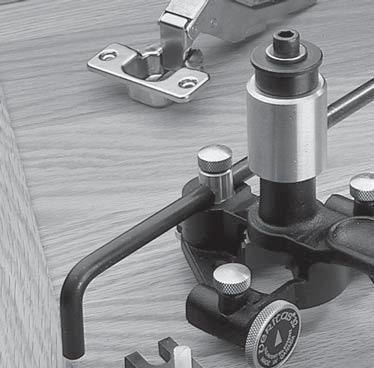
2 This versatile jig contains a built-in carbide cutter and is designed to be powered by your own electric drill. It will locate cup and screw holes for 35mm cup hinges. With this handy tool you can avoid an expensive production-line machine tool or a specially jigged drill press and, of course, it fits into your toolbox for outside work. 35mm Cup Hinge Hole Hinge Base Plate Base Plate Screw Mounting Holes Hinge Screw Mounting Holes 35mm Cup Hinge 32mm 37mm Figure 1: Jig locates cup and screw holes for 35mm cup hinges. Just set the depth and lateral adjustments explained in the following instructions and this jig will give you accurately placed, squarely driven cup and screw holes in the door. Also, if the inside wall partition does not have a row of 32mm spaced holes to receive the base plate that anchors the other end of the hinge, this jig will easily locate a pair of these for you. As an added feature, the jig can be set up to install compact flap hinges or double cup hinges in which the cup holes actually break through the edge of the door and through the edge of the corresponding side member of the cabinet. The following information explains the construction in detail and provides step-by-step instructions on operation and maintenance. 2
3 Three-Step Summary Instructions Detailed instructions are contained here, but for those who just want a summary, the following 3-step guide is provided. 1. Set Cutter Depth: with the collar set screw loosened and your thumb holding the cutter up, depress the collar until the bottom of the spring cage is in line with the required depth gauge mark. Relock the collar. 2. Set the Micrometer Fences For Backset: with the micrometer fences screwed in all the way, the 35mm cup hole will just break through the edge of the door (zero backset). With both fence locking thumbscrews loosened, unscrew the micrometer fences one turn for each required millimetre of backset (the screws have a 1mm pitch thread). Tighten the fence locking thumbscrews. 3. Set the Hook Gauge: with the hook gauge in the central hole at the rear of the jig, loosen the thumbscrew, hook the bent rod over the door end, slide the gauge until it is the required distance from the end, and tighten the thumbscrew. All adjustments for basic 35mm cup holes have now been made, and you are ready to drill. Simply chuck the hex driver in your drill, hold the jig with the micrometer fences and hook gauge against the edges of the door and drill. 3
4 1/4" Hex Driver 1/4"-28 1 /2" Socket Head Capscrew Collar Set Screw Collar Spring Cage Depth Gauge Hook Gauge Thumbscrew Fence Locking Thumbscrews 5/32" Nylon Balls Centerline Marker Screw Holes for Base Plate Backset Drilling Distance Micrometer Fences Hook Gauge 32 mm Screw Holes for Cup Figure 2: Hinge-boring jig components. Detailed Instructions Step 1: Setting the Depth of the Cup Holes Scrap of Wood Figure 3: Preventing the cutter from marking your workpiece. Place the jig on a small scrap of wood that has a small hole ( 1 /8" to 1 /4") in the center, locating the drill center-point over the hole. This will keep the bit up, preventing the cutter center-point from marking your workpiece. Now, loosen the collar set screw and push the collar down until the bottom of the spring cage lines up with the required cup hinge depth reading on the depth gauge. Relock the collar securely. As you proceed to drill with 4
5 this setting, you will note that the cutter stops its downward travel as the bottom of the spring cage engages the ledge on the jig body. The total downward travel is actually more than the depth called for on the depth gauge. This is because free travel is built into the system to ensure that the retracted cutter point will not project below the foot of the jig where it could scratch the workpiece. Step 2: Setting Distance of Cup from Edge of Door (Backset Drilling Distance) The distance of the cup from the door edge is determined by the position of the micrometer fences that project below the jig base and bear against the edge of the door. If these micrometer fences are screwed in tight, the cup drilling distance will have zero backset (i.e., the edge of the cutter will just break through the edge of the door). The threads of the micrometer fences have a 1mm pitch, thus the backset will increase by 1mm with each "back off" turn. Therefore, check the backset requirement of your hinges, zero the fences, and back off one turn for each millimetre called for. Tighten the fence locking thumbscrews. Note that the locking mechanism for the micrometer fences has 5 /32" nylon balls inserted between the ends of the locking thumbscrews and the threads of the adjustment screws. They protect the threads from damage. If you dismantle the fence mechanism, be careful not to lose them. Step 3: Setting Distance Between Hinge and Top or Bottom of Door This distance is set by extending the hook gauge to the desired distance, tightening the thumbscrew, and hooking the gauge over the end of the door. With the hook gauge fixed by the thumbscrew so it cannot slide, it can still be lifted slightly and turned through 180, allowing the jig to be repositioned at the same distance from the opposite end of the door. If the door will be mounted to a cabinet that has a row of 32mm spaced system holes on the inside cabinet wall, set the hook gauge so that the 35mm cup hole will line up centered between a pair of these holes (or in line with one of these holes if you are using the in-line type base plate). 5
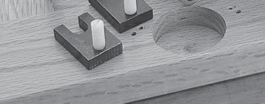
6 Step 4: Holding the Jig and Operating the Electric Drill We recommend that you use a 1 /4" quick-change chuck on your electric drill to engage the hex driver or drill pilot holes. This speeds up the work and provides some flexibility in the drive. Make sure that the micrometer fences and hook gauge are secure and held firmly against their respective work faces. Also, make sure that the foot of the gauge remains flat against the workpiece and does not tilt as drilling progresses. As with any power tool accessory, always wear safety glasses. Please see Care and Maintenance section at the end. Adjusting the Jig to Drill Cups for Compact Flap Hinges These compact hinges, attractive for smaller cabinets, usually have cups on either end (double cup). The compact features require that the cup holes break through the edge of the door and the edge of its adjoining member. To achieve this breakout, one spacer can be clamped under each micrometer fence, as shown in Figure 4. This spacer extends down to hold a second micrometer screw operating parallel to the first. This second screw is made of nylon and is self locking in the threads. It also advances at the rate of 1mm per turn. Hence, set the nylon screw flush with the spacer s inside face and advance it one turn for each millimetre of required breakout. Micrometer Fence Workpiece Micrometer Screw Spacer Flap Hinge Holes Figure 4: Clamping spacer under micrometer fence. 6
7 Retrofitting Existing Cabinets To retrofit new doors onto old cabinets (which do not have a row of 32mm spaced system holes to accommodate the hinge base plates), align the door with the cabinet and mark off hinge center heights at the junction line. These marks can then be extended with a square. With the micrometer fences screwed all the way in, hold the jig over this centerline using the centerline marker located at the front of the jig, and proceed to drill the required pair of 32mm spaced holes (see Figure 1). It is always best to use the hook gauge to firmly position the jig before you start to drill. The resultant holes will be 32mm apart, backset 37mm from the front edge of your cabinet, both the required distances for most hinge base plates. See "A-A" in table on next page. Using the Jig as a Template for Screw Holes X A C B E D Y+ Y- 37 mm Figure 5: Using jig as a template. You will find that the jig base plate comes equipped with five pairs of dimples, which match the more common cup hinge screw patterns. These dimples are designed to be drilled through as required to locate screw pilot holes (either drilled or pricked with an awl). These dimples were not drilled through at the factory because size and type of holes may vary, 7
8 depending on application. For instance, you may want to use only one style of hinge and hence only one pair of dimples should be drilled out to avoid confusion. Plus, for use with 32mm spaced system holes, you may not want the two top holes drilled out. Measure the hinge itself to determine the required spacing and distance of screw holes from the cup centerline. With this information, use the table below to determine which pair of dimples you will need to drill out to provide this template. Instructions below provide more information on procedures for drilling out dimples. Please read this before you proceed. Pair X Y A - A* 32mm 19.5mm B - B 45mm 9.5(+)mm C - C 52mm 5.5(+)mm D - D 48mm 2.5(-)mm E - E 48mm 7.5(-)mm * Used for drilling cabinet system holes only. If you intend to drill out dimples with an ordinary drill, ensure that the bit is well sharpened and has a sharp point to prevent wandering. Note: If you are using a hinge that has screw mounting holes that do not match the provided dimples, you can drill the cup holes fi rst, press the hinges into place and align them with a scrap piece of stock (or other straight edge). Then use the hinge holes themselves as a drilling guide. Scrap Stock Door Hinges Figure 6: Using hinge holes as drilling guide. 8
9 Care and Maintenance There are several rubbing faces in the jig, all of which are lubricated. These faces include the cutter spindle, the cutter thrust face on top of the cutter head, and the thrust face between the collar and the spring cage. The unit should be disassembled periodically for inspection. To do this, block rotation of the cutter by inserting an elongated piece of wood between the cutter spokes and the body framework, then unscrew the hex drive. Further disassembly is evident in Figure 2. Depending on the inspection (i.e., evidence of existing or impending metal-to-metal contact), the grease films should be swabbed and replaced by smearing on fresh grease using a small wooden rod, preferably flattened like a small spade. The annular cavity under the collar should be repacked with fresh grease, as should the adjoining thrust faces of the cutter. Avoid excessive grease build-up, especially at the top of the cutter head, as this may flow out and cause undesirable stains on the workpiece. Use a light viscosity straight mineral grease. Do not use synthetic or additive greases as some of these may attack alloy metals. Always make sure that the jig is firmly held and that thrust to the electric drill is applied straight downwards. As with any power tool accessory, watch for signs of binding or overheating. Stop and correct the cause before resuming operation. Wear safety glasses while drilling. 9
10 Accessories 05J07.02 Replacement 35mm Carbide Cutter 05J06.10 Gauge Head This gauge has an integral rule and stop, allowing the jig to be repeatedly and accurately repositioned. The rule has both metric and Imperial graduations to 6" (15cm). 174 Veritas Tools Inc Proctor Avenue 1090 Morrison Drive Ogdensburg, New York Ottawa, Ontario USA K2H 1C2 Canada INS-039 Rev. B Printed in Canada.
Surface Vise 05G10.50
 Surface Vise 05G10.50 Patent Pending Introduction The Veritas Surface Vise can be used anywhere you can drill two 3 /4" diameter holes, approximately 6" to 10" apart. The front guide supports the unthreaded
Router Table Floor Stand
 Router Table Floor Stand Owner s Manual 05J20.40 Introduction The Veritas Router Table Floor Stand has been designed as a free-standing router table workstation to work with the existing Veritas Router
Quick-Release Front Vise 05G34.01
 Quick-Release Front Vise 05G34.01 Patent Pending Introduction A front vise is the most generally useful vise on a typical workbench. It can be used for clamping parts on edge within the jaws, for clamping
Quick-Release Sliding Tail Vise 05G30.01
 Quick-Release Sliding Tail Vise 05G30.01 U.S. Des. Pat. No. D671,812 U.S. Pat. No. 9,050,710 Introduction The Veritas Quick-Release Sliding Tail Vise is a reworked version of the well-known tail vise that
Front Vise 70G G08.02
 Front Vise 70G08.01 70G08.02 The following instructions guide you through the installation of either the Regular Front Vise (70G08.01) or the Large Front Vise (70G08.02). The first step is to determine
Custom Bench Plane. Honing and Polishing the Blade. Blade Carrier
 Custom Bench Plane U.S. Pat. No. 7,603,783 Your Veritas bench plane has been assembled with the component options you selected when you placed your order. Caution: Be aware that the blade is sharp; careless
Router Plane 05P38.01
 Router Plane 05P38.01 Patent Pending The Veritas Router Plane is an invaluable tool for work on stop or through dadoes, grooves, or any work that requires an area cut to a precise depth. This is the perfect
Skew Block Plane. U.S. Pat. No. 7,603,783 and U.S. Des. Pat. No. D644,904
 Skew Block Plane U.S. Pat. No. 7,603,783 and U.S. Des. Pat. No. D644,904 The Veritas Skew Block Plane combines the best features of a low-angle block plane with those of a skew rabbet plane, making it
Router Plane 05P38.01
 Router Plane 05P38.01 U.S. Pat. No. 7,950,157 The Veritas Router Plane is an invaluable tool for work on stop or through dadoes, grooves, or any work that requires an area cut to a precise depth. This
Ball-Joint Scrapers Steel Blade Carbide Blade 05K K21.04
 Ball-Joint Scrapers Steel Blade Carbide Blade 05K21.01 05K21.04 The Veritas Ball-Joint Scraper is based on a tool originally made by L.S. Starrett Tool Company but out of production for many years. Originally
Right-Angle Sled. Owner s Manual 05J U.S. Patent No. 5,890,524
 Right-Angle Sled Owner s Manual 05J24.01 U.S. Patent No. 5,890,524 Introduction The Veritas Right-Angle Sled straddles the Veritas Router Fence, giving rock solid support to the right-angle arm. As with
Due to possible damage in shipping, the vertical stop assembly has been removed from this machine.
 Due to possible damage in shipping, the vertical stop assembly has been removed from this machine. To assemble, insert the threaded rod through the shroud opening in the top of the machine. Start the four
Beading Tool 05P04.50
 Beading Tool 05P04.50 U.S. Des. Pat. D591,580 The Veritas Beading Tool allows you to quickly and easily add fine details to furniture by hand, without the substantial set-up and jigging that a router would
Fig. 2 DORMA-Glas Stand/Issue 02/03 Seite/Page 1/7
 FSW Installation instructions Track rail 75 x 72 mm 1. Ceiling substructure and installation of the track rail (Fig. 1): The track rail must be bolted over its entire length (including the stacking track
Tools: Sharpie, Square, Vise, Hack saw, Ruler, Punch, Hammer, File. 2. Cut the stock Place stock in vise and cut with hack saw
 Purpose: MAKE CATAPULT ARM Step 1 Tools: Sharpie, Square, Vise, Hack saw, Ruler, Punch, Hammer, File Materials: Flat aluminum ½ inch stock (see picture below) Gloves required 1. Pick up the aluminum ½
Wooden Plane. Hardware Kit. 05P Blade packaged separately.
 Wooden Plane Hardware Kit Veritas Tools Inc. Ottawa ON K2H 1C2 Canada Ogdensburg NY 13669-2205 United States www.veritastools.com 05P40.45 W22356p@AEBHe Blade packaged separately. Introduction The following
Page 1. SureMotion Quick-Start Guide: LARSACC_QS 1st Edition - Revision A 03/15/16. Standard Steel Bolt/Screw Torque Specifications
 R K C T I Repair Kit Product Compatibility Repair Kit # Linear Actuator Assembly # LARSACC-013 LARSACC-014 LARSD2-08T12BP2C (12-in travel) LARSD2-08T24BP2C (24-in travel) C P I R K 1 ea Ball Screw with
Small Plow Plane. U.S. Des. Pat. No. D591,579
 Small Plow Plane U.S. Des. Pat. No. D591,579 The Veritas Small Plow Plane is a joinery plane, perfect for cutting grooves, such as used for drawer and box bottoms, cabinet backs, and frame-and-panel construction.
Handle Hardware Kit for Router Plane 05P38.10
 Handle Hardware Kit for Router Plane 05P38.10 Introduction With this kit, you can make a set of replacement handles for the Veritas Router Plane. The following instructions describe how to make one handle
MODEL H " BYRD SHELIX CUTTERHEAD INSTRUCTIONS
 MODEL H9291 12" BYRD SHELIX CUTTERHEAD INSTRUCTIONS The Model H9291 12" Byrd Shelix cutterhead is designed to replace the straight-knife cutterhead on the Grizzly jointer Model G0609. The total procedure
ED1300/1300F SERIES CONCEALED VERTICAL ROD DEVICE INSTALLATION INSTRUCTIONS
 ED1300/1300F SERIES CONCEALED VERTICAL ROD DEVICE INSTALLATION INSTRUCTIONS Ver.2 1300 SERIES CONCEALED VERTICAL ROD DEVICE Top Strike Latch Screws Strike Screws Release Plunger Top Latch Plunger Screws
w w w. h d o n l i n e s h o p. d e TIMKEN BEARING CONVERSION TOOL GENERAL INSTALLATION -J04672 REV Kit Number Models
 -J067 REV. 008-07- GENERAL Kit Number 8-08 Models TIMKEN BEARING CONVERSION TOOL For model fitment information, see the P&A Retail Catalog or the Parts and Accessories section of www.harley-davidson.com
Hinge Mortise Plane 05P38.70
 Hinge Mortise Plane 05P38.70 U.S. Pat. No. 7,950,157 The Veritas Hinge Mortise Plane is specifically designed for quickly and accurately cutting shallow mortises, such as those required for butt hinges,
INSTRUCTIONS FOR HIT LOCK MORTISER
 1825 VIA BURTON ANAHEIM CA 92806 714-772-5202 / FAX 714-772-2302 EMAIL: MAIL@MAJORMFG.COM WEB: WWW.MAJORMFG.COM INSTRUCTIONS FOR HIT-66-200 LOCK MORTISER WHEN USING POWER TOOLS ALWAYS WEAR EYE AND EAR
M4 Foot Operated Underpinner Instruction Manual
 M4 Foot Operated Underpinner Instruction Manual M4 Walker Rd, Bardon Hill, Coalville, Leicestershire LE67 1TU, England Tel. +44 (0)130 1692, Fax +44 (0)130 16929 e mail sales@framerscorner.co.uk M4 Underpinner
Inventory (Figure 2)
") MODEL T10127 12" SPIRAL CUTTERHEAD INSTRUCTIONS The Model T10127 indexable insert spiral cutterhead is designed to replace the straightknife cutterhead from the Grizzly jointer Model G0609. The total procedure
MODEL T10127 12" SPIRAL CUTTERHEAD INSTRUCTIONS The Model T10127 indexable insert spiral cutterhead is designed to replace the straightknife cutterhead from the Grizzly jointer Model G0609. The total procedure
15 Dovetail Jig. Instruction Manual. Part # 3452
 15 Dovetail Jig Instruction Manual Part # 3452 CAUTION: Please read, understand, and follow all manufacturers instructions, guidelines and owners manuals that come with your power tools. Peachtree Woodworking
Model: SCD430 SCD640. Installation & Operation Guide P/N SCD640-95
 Model: SCD430 SCD640 Installation & Operation Guide P/N SCD640-95 Model SCD430 and SCD640 Kurt has two Self-Centering vises, a four-inch jaw width (SCD430) and a six-inch jaw width (SCD640). Jaw opening
Bevel-Up Jack Rabbet Plane
 Bevel-Up Jack Rabbet Plane U.S. Pat. Nos. 7,603,783 & 7,117,602 The Veritas Bevel-Up Jack Rabbet Plane is predominantly used for large-scale rabbets, as well as raised panel work anywhere you need to make
Model D1700/D1701 Moulding Head Instruction Sheet
 Model D1700/D1701 Moulding Head Instruction Sheet Phone #: (360) 734-3482 Online Tech Support: tech-support@shopfox.biz Web: www.shopfox.biz To reduce risk of serious personal injury when using moulding
Bullnose Plane 05P42.01
 Bullnose Plane 05P42.01 Patent Pending The Veritas Bullnose Plane, perfect for cleaning up machine-cut joints, will be one of the most useful hand joinery tools you ll ever own. Designed for maximum versatility,
GlideRite Retractable Cover System For Hot Spot Spas (SE & SLX only)
") List of Contents Quantity Description 12 #10 x 1 ½ Flat Head Phillips Screw (see pg. 2) 2 #10 x ½ Pan Head Phillips Screw (see pg. 2) 8 ¼ x 2 ½ Lag Bolt (see pg. 2) 7 ¼ 20 x 5 / 8 Hex Head Bolt (see pg.
List of Contents Quantity Description 12 #10 x 1 ½ Flat Head Phillips Screw (see pg. 2) 2 #10 x ½ Pan Head Phillips Screw (see pg. 2) 8 ¼ x 2 ½ Lag Bolt (see pg. 2) 7 ¼ 20 x 5 / 8 Hex Head Bolt (see pg.
Small Scraping Plane 05P29.50
 Small Scraping Plane 05P29.50 U.S. Des. Pat. D609,548 The Veritas Small Scraping Plane is used for the final smoothing of small, flat surfaces, even if they are highly figured, or small areas of difficult
MORTISE LOCK INSTALLATION INSTRUCTIONS
 MORTISE LOCK INSTALLATION INSTRUCTIONS INSPIRE TM ROSELESS DESIGNER TRIM FM 340 Rev. 10/18 TABLE OF CONTENTS: DOOR PREPARATION 1 ML2000 LOCK HANDING 2 FULL WORKING TRIM (STD) 3 HALF WORKING TRIM (M30)
MODEL T " HELICAL CUTTERHEAD INSTALLATION INSTRUCTIONS
 MODEL T27696 12" HELICAL CUTTERHEAD INSTALLATION INSTRUCTIONS For questions or help with this product contact Tech Support at (570) 546-9663 or techsupport@grizzly.com Introduction The Model T27696 indexable
Safety glasses Measuring tape Level Pencil Power drill Center punch Phillips screw driver Saw horse
 EX76 Concealed Vertical Rod Exit Device Preparation Guide and Installation Instructions Box Contents EX76 Concealed Vertical Rod Exit Device Back Bar Active Push Bar Filler Plate Door Kit with Templates
Spokeshaves. U.S. Des. Pat. D499,770
 Spokeshaves U.S. Des. Pat. D499,770 Introduction The Veritas spokeshaves have been designed for smooth, effective shaping of chair spindles, tool handles, panel edges, paddle shafts, etc. The large spokeshave
GlideRite Retractable Cover System For HotSpring & Tiger River Spas (except Classic & pre-2000 Landmark Spas)
") List of Contents Quantity Description 12 #10 x 1 ½ Flat Head Phillips Screw (see pg. 2) 2 #10 x ½ Pan Head Phillips Screw (see pg. 2) 8 ¼ x 2 ½ Lag Bolt (see pg. 2) 7 ¼ 20 x 5 / 8 Hex Head Bolt (see pg.
List of Contents Quantity Description 12 #10 x 1 ½ Flat Head Phillips Screw (see pg. 2) 2 #10 x ½ Pan Head Phillips Screw (see pg. 2) 8 ¼ x 2 ½ Lag Bolt (see pg. 2) 7 ¼ 20 x 5 / 8 Hex Head Bolt (see pg.
Additional Information
 NUMBER: 1 34 13 S.M. REF.: Listed in Table ENGINE: EPA04/07 Series 60 DATE: January 2013 SUBJECT: CHECKING CYLINDER LINER PROTRUSION ADDITIONS, REVISIONS, OR UPDATES Publication Number Platform Section
Hinge Mortising Jig. One of the make it or break it parts of building a. 6 ShopNotes No. 74
 Hinge Mortising Jig A Mortise for a Hinge. Quick, clean, and accurate that s the only way to describe the mortise you get with a trim router and this hinge mortising jig. One of the make it or break it
Installation for Full Size Polaris Ranger Crew Doors
 Installation for Full Size Polaris Ranger Crew Doors Order of Installation: Heater Doors Wiper on to Windshield Windshield Top & Back Panel Note: Most of the steps in these instructions need to be repeated
1. TOOLS + MATERIALS REQUIRED
 R INSTALLATION INSTRUCTIONS PRODUCT: BALDUR + ODEN CONFIGURATION: BI-PARTING DOOR MOUNT: TOP MOUNT Product is covered by U.S. patents. For more information visit www.krownlab.com. TOOLS + MATERIALS REQUIRED
DX60 Block Plane 05P70.01
 DX60 Block Plane 05P70.01 U.S. Des. Pat. D612,701 The body of this block plane by Veritas is ductile cast iron, a material much more durable as well as more stable than gray iron, having been fully stress
INSTALLATION & OWNER S MANUAL
 Rev. O p. 1 of 16 INSTALLATION & OWNER S MANUAL V4213 BALL CAGE KIT INSTALLATION & OWNER S MANUAL The contents of this envelope are the property of the owner. Be sure to leave with the owner when installation
HDL(M)6 Nut/Screw Assembly
6 Nut/Screw Assembly") HDL(M)6 Nut/Screw Assembly Remove, repair, and reassemble the nut and screw assembly in your HDL series double lock vise. In these instructions when we refer to the front of the vise or nut/screw assembly,
HDL(M)6 Nut/Screw Assembly Remove, repair, and reassemble the nut and screw assembly in your HDL series double lock vise. In these instructions when we refer to the front of the vise or nut/screw assembly,
1) Place the reactor stand on a sturdy bench with the bottom plate facing toward the front.
 Place the reactor stand on a sturdy bench with the bottom plate facing toward the front.") Assembly Instructions for ChemRxnHub Reactor Systems 1) Place the reactor stand on a sturdy bench with the bottom plate facing toward the front. Loosen knobs on the right and left using 2 hands of the
Assembly Instructions for ChemRxnHub Reactor Systems 1) Place the reactor stand on a sturdy bench with the bottom plate facing toward the front. Loosen knobs on the right and left using 2 hands of the
TABLE OF CONTENTS REQUIRED TOOLS
 TABLE OF CONTENTS SECTION SECTION TITLE PAGE NO. 1 2 3 4 5 Assembling Mounting Structure Installing Bicycle Supports Mounting Rack to Wall Adding Sections Customizing Rack Configuration REQUIRED TOOLS
Lapping Plate 05M20.20
 Lapping Plate 05M20.20 U.S. Des. Pat. D593,140 Lapping is the process of rubbing two surfaces together with an abrasive and a lubricant to improve the quality of at least one of the surfaces. Although
1904, 1904Pg, 1904PgSB, and 1906SB High Capacity Ratchet Knockout Drivers
 INSTRUCTION MANUAL 1904, 1904Pg, 1904PgSB, and 1906SB High Capacity Ratchet Knockout Drivers Read and understand all of the instructions and safety information in this manual before operating or servicing
Joiner Kit For Models N388, C450, E402B, E411T, E415H, E440T, E442B, E521T and E522B
 Joiner Kit For Models N388, C450, E402B, E411T, E415H, E440T, E442B, E521T and E522B KIT COMPONENTS Part Illustration Description Rear Bracket Front Lower Bracket Front Upper Bracket KIT APPLICATION This
PAN AND BOX BRAKE INSTRUCTIONS. Item #20649
 PAN AND BOX BRAKE INSTRUCTIONS Item #20649 The EASTWOOD 12 & 24 PAN AND BOX BRAKES are precision engineered metal working tools designed to produce accurate, variable length bends in angles up to 135 in
Spokeshaves. U.S. Des. Pat. D499,770 U.S. Des. Pat. D594,728
 Spokeshaves U.S. Des. Pat. D499,770 U.S. Des. Pat. D594,728 The Veritas spokeshaves have been designed for smooth, effective shaping of chair spindles, tool handles, panel edges, paddle shafts, etc. The
Side Winder R o u t e r L i f t.
 Woodpeckers PRECISION WOODWORKING TOOLS Side Winder R o u t e r L i f t. INSTALLATION INSTRUCTIONS The wrench handle must be pointing left in order to fully insert or remove it. Lift Wrench Once fully
Installing Your Electronic Deadbolt
 Ultra Security Plus Electronic Deadbolt Installation Instructions http://www.hberger.com/video-gallery/electronic-deadbolt New Installation Lock Location Preparation (Skip this section if you door has
BEAST THE. Tube and Pipe Notcher Operating Instructions. Notches In Bends Straight Notches. Angled Notches. Offset Notches
 Copyright (c) 2007 J D SQUARED INC. www.jd2.com THE BEAST Tube and Pipe Notcher Operating Instructions Notches In Bends Straight Notches Angled Notches PATENT PENDING Offset Notches Assembly After unpacking
Copyright 2007 MLCS 1
 Copyright 2007 MLCS 1 REFERENCE GUIDE and SPECIFICATIONS: Edge Guides: This 12 Dovetail Template comes complete with 2 Edge Guide Sets one set for Half Blind and one set for Rabbeted Half Blind Dovetails.
ALWAYS disconnect the power source before using the Betterley UNA-GAUGE with any power tool or machine!
 Betterley UNA-GAUGE Thank you for purchasing the Betterley UNA-GAUGE. You will find the UNA-GAUGE provides quick adjustments and alignment of most tools and machinery with extreme accuracy. The versatile
VARIABLE SPEED WOOD LATHE
 MODEL MC1100B VARIABLE SPEED WOOD LATHE INSTRUCTION MANUAL Please read and fully understand the instructions in this manual before operation. Keep this manual safe for future reference. Version: 2015.02.02
The Portable Open Source 3D Printer
 http://web.archive.org/web/201502142011/http://www.tantillus.org/build_3.html Page 1 of 12 captures 12 Oct 12 - Feb 15 The Portable Open Source 3D Printer Home Start Case X/Y Axis Extruder Z Axis Electronics
Inventory (Figure 2)
") MODEL T10130/T10126 6" & 8" SPIRAL CUTTERHEAD INSTRUCTIONS The Model T10126/T10130 indexable insert spiral cutterheads are designed to replace straightknife cutterheads from the Grizzly jointer Models
MODEL T10130/T10126 6" & 8" SPIRAL CUTTERHEAD INSTRUCTIONS The Model T10126/T10130 indexable insert spiral cutterheads are designed to replace straightknife cutterheads from the Grizzly jointer Models
NUMBER: S.M. REF.: Listed in Table ENGINE: Series 50/50G DATE: October 2013 SUBJECT: MACHINING CYLINDER BLOCK COUNTERBORES
 NUMBER: 10 25 13 S.M. REF.: Listed in Table ENGINE: Series 50/50G DATE: October 2013 SUBJECT: MACHINING CYLINDER BLOCK COUNTERBORES ADDITIONS, REVISIONS, OR UPDATES Publication Number Platform Section
Premium Power Tool Accessories Proudly Made in the USA
 Premium Power Tool Accessories Proudly Made Table of Contents Make it Snappy Tools Premium Power Tool Accessories Proudly Made About Us Founded in a basement machine shop in Minnesota in 1962, we are a
REPAIR INSTRUCTIONS. Cat. No Cat. No MILWAUKEE ELECTRIC TOOL CORPORATION. SDS Max Demolition Hammer. SDS Max Rotary Hammer
 Cat. No. 9-0 SDS Max Demolition Hammer Cat. No. -0 SDS Max Rotary Hammer MILWAUKEE ELECTRIC TOOL CORPORATION W. LISBON ROAD BROOKFIELD, WISCONSIN 00-0 8-9-0 d 000 8-9-0 d Special Tools Require Forcing
BHJ Products, Inc. Parts List & Instructions
 Product Name: Lifter-Tru Kit for Ford Windsor & SVO Small Block V8 Page 1 of 5 Kit Contents: 2x End Plates 2x 5/8 Threaded Adjustment Sleeves 1x Front Angle Bracket 2x 5/8 Adjustment Sleeve Spacers * 1x
OWNER S MANUAL. Safety. Please read this owner s manual before use and keep it at hand for reference. Warranty
 Please read this owner s manual before use and keep it at hand for reference. OWNER S MANUAL Safety Important safety instructions for using the INCRA Miter5000 Before using the INCRA Miter5000, read and
Gared Pro-S Portable Backstop
 Models: 9616 & 9618 Installation, Operation and Maintenance Instructions Please read all instructions before attempting installation or operation of these units SAVE THESE INSTRUCTIONS FOR FUTURE USE PUBLICATION
compile system INSTALLATION GUIDE Updated January 2019
 INSTALLATION GUIDE Updated January 09 compile system Table of Contents Panels 0 Quick Connect Clips 0 Lock Clips 0 Panel Trims 0 Privacy Glass 0 Post Base Covers 04 Electrical 04 Power Distribution Harness
Extendable Large Dovetail Jig
 Extendable Large Dovetail Jig Instruction Manual Part # 3458 CAUTION: Please read, understand, and follow all manufacturers instructions, guidelines and owners manuals that come with your power tools.
Hardware and Components:
 Hardware and Components: (A) 4X 5/16 x 1 Carriage Bolt (B) 2X 5/16 x 2-1/4 Carriage Bolt (C) 2X 5/16 x 3-1/4 Hex Bolt (D) 2X 5/16 x 3/4 Hex Bolt (E) 2X 5/16 x 1-1/4 Hex Bolt (F) 5/16 x 2-1/4 Hex Bolt (G)
PRODUCT: LOKI INSTALLATION INSTRUCTIONS. Product is covered by U.S. patents. For more information visit
 R INSTALLATION INSTRUCTIONS PRODUCT: LOKI CONFIGURATION: SINGLE DOOR MOUNT: GLASS MOUNT Product is covered by U.S. patents. For more information visit www.krownlab.com . TOOLS + MATERIALS REQUIRED TOOLS
MODEL T " SPIRAL CUTTERHEAD INSTALLATION INSTRUCTIONS
 MODEL T27449 8" SPIRAL CUTTERHEAD INSTALLATION INSTRUCTIONS The Model T27449 indexable insert spiral cutterhead is designed to replace the straightknife cutterhead on the Grizzly jointer Model G0490W/G0490XW
Section 1 Cubicles. Section 2 IPS Duct Panel Systems. Section 3 - Vanity Units Components & Assembly 12. Section 4 Basic Maintenance.
 Contents Section 1 Cubicles Cubicle Components 3 Cubicle Installation 4-5 Cubicle Fittings Brackets 6 Hinges 7 Partition Support Leg 8 Indicator Bolt 9 Section 2 IPS Duct Panel Systems Frame, Flash & Panel
Tectus TE 680 3D FD TECTUS TE 680 3D FD. The concealed hinge system for timber entrance doors
 Tectus TE 680 3D FD TECTUS TE 680 3D FD The concealed hinge system for timber entrance doors 2 Tectus TE 680 3D FD Index TECTUS TE 680 3D FD The concealed hinge system for timber entrance doors 4 Sealing
Hardware and Components:
 Hardware and Components: (A) 5/16 x 2 Hex Bolt (B) 5/16 x 2-1/4 Hex Bolt (C) 5/16 x 2-1/2 Hex Bolt (D) 4X 5/16 x 3/4 Hex Bolt (E) 4X 5/16 x 1-1/4 Hex Bolt (F) 11X 5/16 Flat Washer (G) 12X 5/16 Nylock Nut
MODEL 36 Di-Acro Hand Shear
 OPERATOR S MANUAL & INSTRUCTIONS MODEL 36 Di-Acro Hand Shear Di-Acro, Incorporated PO Box 9700 Canton, Ohio 44711 3713 Progress Street N.E. Canton, Ohio 44705 330-455-1942 330-455-0220 (fax) Revised 01/02
Agricultural Mechanics and Technology Power Tool Safety Rules
 Agricultural Mechanics and Technology Power Tool Safety Rules Name: BAND SAW Use: Cutting curves, circles and irregular shapes. 1. Use clean SHARP blades. 2. The teeth should always point DOWN. 3. Adjust
ATTACH WALL PLATE TO WALL
 DANGER! The Elite ar m contains high p r e s s u r e g a s s p r i n g s. T h e following cautions MUST be observed to avoid serious injury. 1. Do not attempt to adjust your Elite arm until everything
Flat Panel Dual Swing Arm Wall Mount (FWD-110) MSP-SA
 MSP-SA") INSTALLATION INSTRUCTIONS Flat Panel Dual Swing Arm Wall Mount (FWD-110) The dual arm wall mount was designed to support flat panel displays with 10 to 30 diagonal screens and weighing a maximum of 40
INSTALLATION INSTRUCTIONS Flat Panel Dual Swing Arm Wall Mount (FWD-110) The dual arm wall mount was designed to support flat panel displays with 10 to 30 diagonal screens and weighing a maximum of 40
INSTALLATION INSTRUCTIONS Small Flat Panel Height-Adjustable, Extended Pitch Swing Arm Wall Mount Model KWE-110
 INSTALLATION INSTRUCTIONS Small Flat Panel Height-Adjustable, Extended Pitch Swing Arm Wall Mount Model KWE-110 The KWE dual swing arm wall mount is designed to provide a broad range of viewing for Small
(6) Plastic Retainers. Passenger/Right. Passenger/Right Support Brackets
 Plastic Retainers. Passenger/Right. Passenger/Right Support Brackets") PART#R102580 PARTS LIST: 1 Driver/Left HD Running Board 4 8mm Bolt/Nut Plates 1 Passenger/Right HD Running Board 4 8mm Plastic Retainers 2 Driver/Left & Center Mount Bracket 14 8mm-1.25 x 30mm Hex Bolts
PART#R102580 PARTS LIST: 1 Driver/Left HD Running Board 4 8mm Bolt/Nut Plates 1 Passenger/Right HD Running Board 4 8mm Plastic Retainers 2 Driver/Left & Center Mount Bracket 14 8mm-1.25 x 30mm Hex Bolts
Scraping Plane 05P29.01
 Scraping Plane 05P29.01 U.S. Pat. No. 7,444,750 The Veritas Scraping Plane is used for the final levelling and smoothing of large, flat surfaces, even if they are highly figured, prior to applying a finish.
Dovetail Saw Guides. Figure 1: Dovetail saw guide, exploded view. Guide Block. UHMW Friction Pad. Sliding Clamp. Rare-Earth Magnet
 Dovetail Saw Guides U.S. Pat. No. 6,607,016 Dovetail joints have traditionally been the hallmark of a cabinetmaker who had acquired an expert level of skill. They are also a mark of quality and attention
Quick Set Dovetail Jig
 Quick Set Dovetail Jig FOR HELP OR ADVISE ON THIS PRODUCT PLEASE CALL OUR CUSTOMER SERVICE HELP LINE : 01509 500359 THE MANUFACTURER RESERVES THE RIGHT TO ALTER THE DESIGN OR SPECIFICATION TO THIS PRODUCT
Tools Required. * When installing on a fire door, please see instructions below. *
 CL615 Tubular Mortice Latch with Code Free option CL615 Tubular Mortice Latch with Code Free option Number relating to picture Item 1 Front Plate and handle * 2 Back Plate and handle * 3 Neoprene seals
INSTALLATION INSTRUCTIONS
 INSTALLATION INSTRUCTIONS PARTS REQUIRED Single QuickStand Lite Parts A (1) Lower Arm A B C D B (1) Upper Arm C (1) Base D (1) Base Plate E (1) M8 Dynamic Arm Long F (1) Clamp Bracket G H (1) VESA Plate
FABA. Installation Instructions. Conductor Bar System. Publication #FABA-03 3/1/04 Part Number: Copyright 2004 Electromotive Systems
 FABA Conductor Bar System Installation Instructions Publication #FABA-03 3/1/04 Part Number: 005-1062 Copyright 2004 Electromotive Systems 1S 100 Z Installation Instructions Contents: Basic Diagram - -
MACHINE TOOL ACCESSORIES
 VERTICAL 5-C COLLET VISE SERIES 344: VERTICAL 3-C COLLET VISE SERIES 344: : 2-1/2 x 7-3/4 Height: 4 Small movement of lever opens or closes collet. 2030000 CAM OPERATED 5-C HORIZONTAL/VERTICAL COLLET FIXTURE
Back-Spotfacing. Flipcut For back-spotfacing and backor front-chamfering operations from one side, in one set-up. Back-Spotfacing. & Chamfering TOOLS
 COGSDILL TOOL PRODUCTS, INC. Flipcut For back-spotfacing and backor front-chamfering operations from one side, in one set-up. Back-Spotfacing & Chamfering TOOLS Back-Spotfacing Available from stock for
S A F T E Y W A R N I N G
 BINDING CUTTING BASE This tool is designed to fit on a Porter Cable Model 310 and 3701 trim router, this combination will provide you with an easy way to accurately cut a binding rabbet on you instrument.
Inventory (Figure 2)
") MODEL T24631 8" SPIRAL CUTTERHEAD Installation INSTRUCTIONS For questions or help with this product contact Tech Support at (570) 546-9663 or techsupport@grizzly.com Introduction The Model T24631 spiral
MODEL T24631 8" SPIRAL CUTTERHEAD Installation INSTRUCTIONS For questions or help with this product contact Tech Support at (570) 546-9663 or techsupport@grizzly.com Introduction The Model T24631 spiral
INSTALLATION INSTRUCTIONS
 TEL -866-XANATOS INSTALLATION INSTRUCTIONS PART#: 7D5000SS\7D500A GRILL GUARD FOR DODGE SPRINTER 07-09 PARTS LIST: 8 6 Grille Guard Driver/Left Frame Mounting Passenger/Right Frame Mounting Driver/Left
RangerWare Fiberglass Door System Installation Instructions P/N
 Page 1 of 9 RangerWare Fiberglass Door System Installation Instructions P/N 2878016 ORDER OF INSTALLATION Note: To assure proper order, read all Accessory Installation Instructions before beginning. 1.
INSTALLATION INSTRUCTIONS REPLACING EXISTING DEADBOLT ASSEMBLY
 INSTALLATION INSTRUCTIONS REPLACING EXISTING DEADBOLT ASSEMBLY A B C L M N D E F G O P Q H I J Tools provided in Amesbury installation kit: (A) door router fixture, (B) doorframe router fixture, (C) ½
Required Tools: Suggested Additional Tools: 1 Cordless Drill with Robertson Bits 1 Ratchet Wrench 1 7/16 or 11mm socket 1 7/16 or 11mm Gear Wrench
 Thank you for your recent purchase of a Cabinets by Hayley garage cabinet system. You are about to experience the best made cabinets that you can purchase. Cabinets by Hayley are designed for beauty and
8" BENCH SHEAR INSTRUCTIONS. Item #20198
 8" BENCH SHEAR INSTRUCTIONS Item #20198 Your EASTWOOD 8 BENCH SHEAR for metal cutting is designed for quickly and cleanly cutting mild steel, aluminum and other metals. Torque-amplifying, compound linkage
DOOR TECHNOLOGY ORDER CATALOG SECTION Tools & Accessories for Door Lock Installation
 DOOR TECHNOLOGY ORDER CATALOG SECTION 03.11 Tools & Accessories for Door Lock Installation Table of Contents 03.11 Tools & Accessories for Door Lock Installation Door Slab Jig...03.11.5 Router Bits for
8mm x 25mm "Z" Bolt Plates. (2) Tube Spacers. (2) 12mm Bolt Plates w/ Nut
 Tube Spacers. (2) 12mm Bolt Plates w/ Nut") PARTS LIST: 1 Grille Guard 10 12mm Lock Washers 1 Driver/Left Side Frame Mounting Bracket 8 12mm Hex Nuts 1 Passenger/Right Side Frame Mounting Bracket 2 10-1.50mm x 25mm Button Head Bolts 1 Driver/Left
PARTS LIST: 1 Grille Guard 10 12mm Lock Washers 1 Driver/Left Side Frame Mounting Bracket 8 12mm Hex Nuts 1 Passenger/Right Side Frame Mounting Bracket 2 10-1.50mm x 25mm Button Head Bolts 1 Driver/Left
Inventory MODEL H7937 TAPER ATTACHMENT FOR THE G0600 LATHE INSTRUCTIONS. Inventory (Figure 1) Needed Items
 Needed Items") MODEL H7937 TAPER ATTACHMENT FOR THE G0600 LATHE INSTRUCTIONS Inventory The Model H7937 taper attachment was carefully packed when it left our warehouse. If you discover it is damaged after you have signed
MODEL H7937 TAPER ATTACHMENT FOR THE G0600 LATHE INSTRUCTIONS Inventory The Model H7937 taper attachment was carefully packed when it left our warehouse. If you discover it is damaged after you have signed
ASSEMBLY INSTRUCTIONS FOR MAR-K BEDSIDES AND GM FLUSH TAILGATE WITH HANDLE
 ASSEMBLY INSTRUCTIONS FOR MAR-K BEDSIDES AND 41-53 GM FLUSH TAILGATE WITH HANDLE Build the box assembly according to the MAR-K assembly instructions. When installing the tailgate and latching mechanisms
PORTABLE ADJUSTABLE BASKETBALL SYSTEM
 Instruction Manual PORTABLE ADJUSTABLE BASKETBALL SYSTEM P A R T S L I S T 5 1/2 and 8 safe play clearance Item Qty Description Item Qty Description A 1 Portable Base Assembly M 4 1/2 Lock Nut B 2 Front