Prasanth. Lathe Machining
|
|
|
- Silas Hudson
- 5 years ago
- Views:
Transcription
1 Lathe Machining Overview Conventions What's New? Getting Started Open the Part to Machine Create a Rough Turning Operation Replay the Toolpath Create a Groove Turning Operation Create Profile Finish Turning Operation Generate NC Code User Tasks Turning Operations Longitudinal Rough Turning Face Rough Turning Parallel Contour Rough Turning Recess Turning Groove Turning Profile Finish Turning Groove Finish Turning Ramp Rough Turning Ramp Recess Turning Thread Turning Sequential Turning Local Information Update Input Stock - Manual Mode Update Input Stock - Automatic Mode Axial Machining Operations Auxiliary Operations Part Operations, Manufacturing Programs and Machining Processes Machining Process for Lathe Machining NC Manufacturing Entities Edit Lathe Tool on an Operation Edit Lathe Tool in Resource List Edit Lathe Tool Assembly in Resource List Edit Lathe Insert in Resource List Verification, Simulation and NC Output Workbench Description Menu Bar Toolbars Specification Tree Customizing General
2 Resources Operation Output Program Photo/Video Reference Information Rough Turning Operations Recess Turning Operations Groove Turning Operations Profile Finish Turning Operations Groove Finish Turning Operations Ramp Rough Turning Operations Ramp Recess Turning Operations Thread Turning Operations Sequential Turning Operations Lathe Tool Assembly Conventions Methodology Cutter Compensation and Finish Operations How to Change the Output Point How to Update Input Stock Glossary Index
3 Overview Welcome to the Lathe Machining User's Guide. This guide is intended for users who need to become quickly familiar with the Lathe Machining Version 5 product. This overview provides the following information: Lathe Machining in a Nutshell Before Reading this Guide Getting the Most Out of this Guide Accessing Sample Documents Conventions Used in this Guide. Lathe Machining in a Nutshell Lathe Machining easily defines NC programs dedicated to machining 3D cylindrical parts using 2-axis turning and drilling operations, for both horizontal and vertical spindle lathe machines. Quick tool path definition is ensured thanks to an intuitive user interface based on graphic dialog boxes. Tools can be easily created and integrated to tool catalogs. Tool path can be generated, simulated and analyzed. Whole manufacturing process is covered from tool path definition to NC data generation thanks to an integrated postprocessor execution engine. Shop floor documentation is automatically created in HTML format. Finally, associativity with Version 5 design products allows productive design change management. Suitable for all kinds of cylindrical machined parts, Lathe Machining fits the needs of Fabrication & Assembly industry, as well as all industries where lathe machining techniques are involved. It can be used in shop-floors as a stand-alone product for CAM-centric customers, who will particularly appreciate the product's ease-of-use and high level of manufacturing capabilities. Lathe Machining can be combined with DELMIA products for overall manufacturing process integration, simulation and optimization, particularly for bigger customers concerned by high quality and quick time-tomarket. Before Reading this Guide Before reading this guide, you should be familiar with basic Version 5 concepts such as document windows, standard and view toolbars. Therefore, we recommend that you read the Infrastructure User's Guide that describes generic capabilities common to all Version 5 products. It also describes the general layout of V5 and the interoperability between workbenches. You may also like to read the following complementary product guides, for which the appropriate license is required: NC Manufacturing Infrastructure User's Guide: explains how to use common Machining functionalities Prismatic Machining User's Guide: provides useful information about axial machining operations. Getting the Most Out of this Guide
4 To get the most out of this guide, we suggest that you start reading and performing the step-by-step Getting Started tutorial. This tutorial will show you how to produce an NC program for turning. Once you have finished, you should move on to the User Tasks section, which gives more complete information about the product's functionalities. The Reference section provides useful complementary information. The Workbench Description section, which describes the commands that are specific to Lathe Machining, and the Customizing section, which explains how to customize settings, and the Methodology section, which provides useful information about recommended work methods, will also certainly prove useful. Accessing Sample Documents To perform the scenarios, you will be using sample documents contained in the doc/online/lmgug_c2/samples or doc/online/lmgug_d2/samples folder. For more information about this, refer to Accessing Sample Documents in the Infrastructure User's Guide.
5 Conventions Certain conventions are used in CATIA, ENOVIA & DELMIA documentation to help you recognize and understand important concepts and specifications. Graphic Conventions The three categories of graphic conventions used are as follows: Graphic conventions structuring the tasks Graphic conventions indicating the configuration required Graphic conventions used in the table of contents Graphic Conventions Structuring the Tasks Graphic conventions structuring the tasks are denoted as follows: This icon... Identifies... estimated time to accomplish a task a target of a task the prerequisites the start of the scenario a tip a warning information basic concepts methodology reference information information regarding settings, customization, etc. the end of a task functionalities that are new or enhanced with this release allows you to switch back to the full-window viewing mode
6 Graphic Conventions Indicating the Configuration Required Graphic conventions indicating the configuration required are denoted as follows: This icon... Indicates functions that are... specific to the P1 configuration specific to the P2 configuration specific to the P3 configuration Graphic Conventions Used in the Table of Contents Graphic conventions used in the table of contents are denoted as follows: This icon... Gives access to... Site Map Split View mode What's New? Overview Getting Started Basic Tasks User Tasks or the Advanced Tasks Workbench Description Customizing Reference Methodology Glossary Index Text Conventions The following text conventions are used: The titles of CATIA, ENOVIA and DELMIA documents appear in this manner throughout the text. File -> New identifies the commands to be used.
7 Enhancements are identified by a blue-colored background on the text. How to Use the Mouse The use of the mouse differs according to the type of action you need to perform. Use this mouse button... Whenever you read... Select (menus, commands, geometry in graphics area,...) Click (icons, dialog box buttons, tabs, selection of a location in the document window,...) Double-click Shift-click Ctrl-click Check (check boxes) Drag Drag and drop (icons onto objects, objects onto objects) Drag Move Right-click (to select contextual menu)
8 Enhanced Functionalities What's New? Enhancements brought by the NC Manufacturing Infrastructure This product benefits from enhancements to the infrastructure's general functions (NC Program Review, NC Resources, Program Management, Geometry Management, Replay and Simulation, NC Data Output, and so on). Please refer to the NC Manufacturing Infrastructure User's Guide for more information.
9 Getting Started Before getting into the detailed instructions for using Lathe Machining, this tutorial is intended to give you a feel of what you can accomplish with the product. It provides the following step-by-step scenario that shows you how to use some of the key functionalities. Open the Part to Machine Create a Rough Turning Operation Replay the Toolpath Create a Groove Turning Operation Create Profile Finish Turning Operation Generate NC Code

10 Open the Part to Machine This first task shows you how to open a part, enter the Lathe Machining workbench and make basic modifications to the Part Operation. 1. Select File > Open then select the Lathe01.CATPart document. 2. Select Machining > Lathe Machining from the Start menu. The Lathe Machining workbench appears. The part is displayed in the Setup Editor window along with the manufacturing specification tree. 3. Double click Part Operation.1 in the tree to display the Part Operation dialog box. 4. Click the Machine icon. The Machine Editor dialog box appears. Select the Horizontal Lathe Machine icon. Set the spindle axis to Z and the radial axis to X. Click OK. Setting the spindle axis to Z defines the C-axis (that is, rotary motion about the Z-axis). This allows creation of indexed machine rotations for milling and drilling operations. 5. Set the tool change point in the Position tab page as shown below.

11 6. Click OK to confirm your modifications to the Part Operation. 7. Select Manufacturing Program.1 in the tree to make it the current entity. To insert program entities such as machining operations, tools and auxiliary commands you can either: make the program current before clicking the insert program entity command click the insert program entity command then make the program current.

12 Create a Rough Turning Operation This task shows you how to create a Longitudinal Rough Turning operation for machining part of the workpiece. This operation will use the tool proposed by the program, so you just need to specify the geometry to be machined and set some of the machining parameters. 1. Select the Rough Turning icon. A Rough Turning.1 entity along with a default tool is added to the program. The Rough Turning dialog box appears directly at the Geometry tab page. 2. Click the red Stock area in the icon, then select the stock profile as shown. Click OK in the Edge Selection toolbar to end your selection. 3. Click the red Part area in the icon, then select the part profile as shown. Click OK in the Edge Selection toolbar to end your selection.

13 4. Select the Strategy tab page and set the parameters as shown. 5. Click OK to create the operation.

14 Replay the Tool Path This task shows you how to replay the tool path of the Roughing operation. 1. Select the Roughing operation in the tree then select the Replay Tool Path icon. The Replay dialog box appears. 2. Choose the Continuous replay mode by means of the drop down icon. 3. Click the button to position the tool at the start point of the operation. 4. Click the button to start the replay. The tool moves along the computed trajectory. 5. Click OK to quit the replay mode.

15 Create a Groove Turning Operation This task shows you how to create a Groove Turning operation to machine part of the workpiece. You will specify the geometry to be machined, set some of the machining parameters and select a new tool. Make sure that the Rough Turning operation is the current entity in the program. 1. Select the Groove Turning icon. The Groove Turning dialog box appears directly at the Geometry page. 2. Click the red Stock area in the icon, then select the stock profile as shown. 3. Click the red Part area in the icon, then select the groove profile as shown. 4. Select the Strategy tab page and check machining parameters. Set the Gouging Safety 5. Angle to 10 degrees. Select the Tool tab in the Tooling tab page. Enter a name of the new tool (for example, Grooving Tool). Double click the l2 (shank length 2) parameter in the icon, then enter 60mm in the Edit Parameter dialog box. Set the Max cutting depth Technology parameter to 80mm.

16 6. Click Replay in the dialog box to visually check the operation's tool path. Click OK to exit the replay mode and return to the Groove Turning dialog box. 7. Click OK to create the operation.

17 Create a Profile Finish Turning Operation This task shows you how to insert a Profile Finish Turning operation in the program. 1. Select the Profile Finish Turning icon. The Profile Finish Turning dialog box appears directly at the Geometry page. 2. Select the red part in the sensitive icon then select the part profile. 3. Select the Strategy tab page and set the Leading Safety Angle to 0 degrees. 4. Click Replay to replay the operation as described previously. Click OK to exit the replay mode and return to the Profile Finish Turning dialog box. 5. Click OK to create the operation in the program.
18 Generate NC Code This task shows you how to generate NC code from the program. An APT source file will be generated in this example. Before doing this task, double click the Part Operation entity in the tree and, in the dialog box that appears, click the Machine icon to access the Machine Editor dialog box. Make sure that you have selected a Horizontal lathe machine and that the desired NC data format is set to Axis (X, Y, Z). 1. Use the right mouse key on the Manufacturing Program.1 entity in the tree to select Generate NC Code Interactively. The Generate NC Output Interactively dialog box appears.

19 2. Select APT as the desired NC data type. 3. Click the Output File button to select the folder where you want the file to be saved and specify the name of the file. 4. Click Execute to generate the APT source file. An extract from a typical APT source file is given below. $$ $$ Generated on Wednesday, April 07, :16:08 AM $$ CATIA APT VERSION 1.0 $$ $$ Manufacturing Program.1 $$ Part Operation.1 $$*CATIA0 $$ Manufacturing Program.1 $$ $$ $$ PARTNO Part Operation.1 $$ OPERATION NAME : Turning Tool Change.1 $$ Start generation of : Turning Tool Change.1 $$ TOOLCHANGEBEGINNING CUTTER/ TOOLNO/1,TURN,1,0,9, ,$ , , ,MMPR, ,RPM,$ CCLW,ON, ,NOTE TPRINT/T1 External Insert-Holder,T1 External Insert-Holder,Turning Tool$ Assembly.1 LOADTL/1,1,1 $$ TOOLCHANGEEND $$ End of generation of : Turning Tool Change.1 $$ OPERATION NAME : Rough Turning.1 $$ Start generation of : Rough Turning.1 SWITCH/9 FEDRAT/ ,MMPR SPINDL/ ,RPM,CCLW GOTO / , , GOTO / , , FEDRAT/ ,MMPR GOTO / , , $$ End of generation of : Rough Turning.1 $$ OPERATION NAME : Turning Tool Change.2 $$ Start generation of : Turning Tool Change.2 $$ TOOLCHANGEBEGINNING CUTTER/ TOOLNO/1,TURN,1,0,9, ,$ , , ,MMPR, ,RPM,$ CCLW,ON,,NOTE TPRINT/T3 External Groove Insert-Holder,T3 External Groove Insert-Holde$ r,turning Tool Assembly.1_1 LOADTL/1,1,1 $$ TOOLCHANGEEND $$ End of generation of : Turning Tool Change.2 $$ OPERATION NAME : Groove Turning.1 $$ Start generation of : Groove Turning.1 SWITCH/9 FEDRAT/ ,MMPR SPINDL/ ,RPM,CCLW GOTO / , ,
20 GOTO / , , RAPID GOTO / , , $$ End of generation of : Groove Turning.1 $$ OPERATION NAME : Turning Tool Change.3 $$ Start generation of : Turning Tool Change.3 $$ TOOLCHANGEBEGINNING CUTTER/ TOOLNO/1,TURN,1,0,9, ,$ , , ,MMPR, ,RPM,$ CCLW,ON, ,NOTE TPRINT/T1 External Insert-Holder,T1 External Insert-Holder,Turning Tool$ Assembly.1 LOADTL/1,1,1 $$ TOOLCHANGEEND $$ End of generation of : Turning Tool Change.3 $$ OPERATION NAME : Profile Finish Turning.1 $$ Start generation of : Profile Finish Turning.1 SWITCH/9 FEDRAT/ ,MMPR SPINDL/ ,RPM,CCLW GOTO / , , GOTO / , , GOTO / , , FEDRAT/ ,MMPR GOTO / , , $$ End of generation of : Profile Finish Turning.1 FINI
21 User Tasks The user tasks you will perform with Lathe Machining involve creating, editing and managing machining operations and other Machining entities. Turning Operations Axial Machining Operations Auxiliary Operations Part Operations, Manufacturing Programs and Machining Processes NC Manufacturing Entities Verification, Simulation and NC Output
22 Turning Operations The tasks in this section show you how to create turning operations in your manufacturing program. Create a Rough Turning operation: Select the Rough Turning icon and choose the desired roughing mode. You can then select the part and stock geometry and specify the tool to be used. Specify machining parameters, feeds and speeds, and NC macros as needed. Basic tasks illustrate the following roughing modes: Longitudinal Face Parallel Contours. Create a Recess Turning operation: Select the Recess Turning icon and choose the desired recessing mode. You can then select the part and stock geometry and specify the tool to be used. Specify machining parameters, feeds and speeds, and NC macros as needed. Create a Groove Turning operation: Select the Groove Turning icon then select the part and stock geometry and specify the tool to be used. Specify machining parameters, feeds and speeds, and NC macros as needed. Create a Profile Finish Turning operation: Select the Profile Finish Turning icon then select the part profile and specify the tool to be used. Specify machining parameters, feeds and speeds, and NC macros as needed. Create a Groove Finish Turning operation: Select the Groove Finish Turning icon then select the part geometry and specify the tool to be used. Specify machining parameters, feeds and speeds, and NC macros as needed. Create a Ramp Rough Turning operation. Select the Ramp Rough Turning icon then select the part and stock geometry and specify the tool to be used. Specify machining parameters, feeds and speeds, and NC macros as needed. Create a Ramp Recess Turning operation. Select the Ramp Recess Turning icon then select the part and stock geometry and specify the tool to be used. Specify machining parameters, feeds and speeds, and NC macros as needed. Create a Thread Turning operation: Select the Thread Turning icon and choose the desired thread type. You can then select the part geometry and specify the tool to be used. Specify machining parameters, feeds and speeds, and NC macros as needed. Create a Sequential Turning operation: Create and manage a sequence of basic Go Standard, Go-Go, Go InDirv, Go Delta, and Follow tool motions in a single operation. Manage Local Information: Assign local feedrates and local offsets to Lathe Profile Finishing and Groove Finishing operations. Update Input Stock: choose to either update the stock automatically by setting an option on the Part Operation or update the stock manually for each lathe operation or axial machining operation along the spindle axis.
.")
23 Create a Longitudinal Rough Turning Operation This task illustrates how to create a Longitudinal Rough Turning operation in the program. To create the operation you must define: the geometry to be machined the tool that will be used the parameters of the machining strategy the feedrates and spindle speeds the macros (transition paths). Open the Lathe01.CATPart document, then select Machining > Lathe Machining from the Start menu. Make the Manufacturing Program current in the specification tree. 1. Select the Rough Turning icon. A Rough Turning entity along with a default tool is added to the program. The Rough Turning dialog box appears directly at the Geometry tab page. This tab page includes a sensitive icon to help you specify the geometry to be machined. The part and stock of the icon are colored red indicating that this geometry is required. All other geometry is optional. 2. Click the red part in the icon then select the desired part profile in the 3D window. The Edge Selection toolbar appears to help you with contour selection. The Automatic Linking option allows you to select a first element then the element to navigate to in order to complete the profile selection. The Axial/Radial and Radial/Axial Linking options are also useful for profile selection. The part of the icon is now colored green indicating that this geometry is now defined.

24 3. Click the red stock in the icon then select the desired stock profile in the 3D window. 4. Set Part Offset to 5mm. 5. Select the Strategy tab page to specify the main machining strategy parameters: Roughing mode: Longitudinal Orientation: External Location: Front. 6. Double click Max depth of cut in the icon. Set this value to 15mm in the Edit Parameter dialog box and click OK. Other optional parameters can be set in the Options tab (lead-in and so on). A tool is proposed by default when you want to create a machining operation. If the proposed tool is not suitable, just select the Tool tab page to specify the tool you want to use. Please refer to Edit the Tool of a Lathe Operation. 7. Select the Feeds and Speeds tab page to specify the feedrates and spindle speeds for the operation. See Feeds and Speeds for Rough Turning for more information. 8. Select the Macros tab page to specify the operation's transition paths (approach and retract motion, for example). Approach linking and retract linking motions are interruptable for this type of operation. See Define Macros on a Lathe Operation for more information.

25 Before accepting the operation, you should check its validity by replaying the tool path. 9. Click OK to create the operation.
26 Create a Face Rough Turning Operation This task shows how to insert a Face Rough Turning operation in the program. To create the operation you must define: the geometry to be machined the tool that will be used the parameters of the machining strategy the feedrates and spindle speeds the macros (transition paths). Open the Lathe01.CATPart document, then select Machining > Lathe Machining from the Start menu. Make the Manufacturing Program current in the specification tree. 1. Select the Rough Turning icon. The Rough Turning dialog box appears directly at the Geometry tab page. This page includes a sensitive icon to help you specify the geometry to be machined. The part and stock in the icon are colored red indicating that this geometry is required for defining the operation. 2. Click the red part in the icon then select the desired part profile in the 3D window. The part of the icon is now colored green indicating that this geometry is now defined. 3. Click the red stock in the icon then select the desired stock profile in the 3D window. 4. Set Part Offset to 5mm.

27 5. Select the Strategy tab page to specify the main machining strategy parameters: Roughing mode: Face Orientation: External Location: Front. 6. Double click Max depth of cut in the icon. Set this value to 10mm in the Edit Parameter dialog box and click OK. 7. In the Options tab, set the lift-off distance to 1.5mm. A tool is proposed by default when you want to create a machining operation. If the proposed tool is not suitable, just select the Tool tab page to specify the tool you want to use. This is described in Edit the Tool of a Lathe Operation. 8. Select the Feeds and Speeds tab page to specify the feedrates and spindle speeds for the operation. See Feeds and Speeds for Rough Turning for more information. If you want to specify approach and retract motion for the operation, select the Macros tab page to specify the desired transition paths. Approach linking and retract linking motions are interruptable for this type of operation. See Define Macros on a Lathe Operation for more information.

28 9. Check the validity of the operation by replaying the tool path. 10. Click OK to create the operation.
29 Create a Parallel Contour Rough Turning Operation This task shows how to insert a Parallel Contour Rough Turning operation in the program. To create the operation you must define: the geometry to be machined the tool that will be used the parameters of the machining strategy the feedrates and spindle speeds the macros (transition paths). Open the Lathe01.CATPart way. document, then select Machining > Lathe Machining from the Start menu. Make the Manufacturing Program current in the specification tree. 1. Select the Rough Turning icon. A Rough Turning entity along with a default tool is added to the program. The Rough Turning dialog box appears directly at the Geometry tab page. This tab page includes a sensitive icon to help you specify the geometry to be machined. The part and stock of the icon are colored red indicating that this geometry is required. 2. Click the red part in the icon, then select the desired part profile in the 3D window. Select the stock in the same

30 3. Select the Strategy tab page to specify the main machining strategy parameters: Roughing mode: Parallel Contour Orientation: External Location: Front Machining direction: To head stock. 4. Double click Axial depth of cut in the icon. Set this value to 3mm in the Edit Parameter dialog box and click OK. Set Radial depth of cut to 3mm in the same way. Other optional parameters can be set in the Options tab (lead-in and so on). When recess machining is active in Parallel Contour Rough Turning, Axial and Radial Depth of Cut must have suitable values to ensure a collision free toolpath. See Recommendations for more information. 5. A tool is proposed by default when you want to create a machining operation. If the proposed tool is not suitable, just select the Tool tab page to specify the tool you want to use. This is described in Edit the Tool of a Lathe Operation. 6. Select the Feeds and Speeds tab page to specify the feedrates and spindle speeds for the operation. See Feeds and Speeds for Rough Turning for more information. 7. If you want to specify approach and retract motion for the operation, select the Macros tab page to specify the desired transition paths. Approach linking and retract linking motions are interruptible for this type of operation. See Define Macros on a Lathe Operation for more information.

31 8. Check the validity of the operation by replaying the tool path. 9. Click OK to create the operation.
.")
32 Create a Recess Turning Operation This task shows how to insert a Recess Turning operation in the program. To create the operation you must define: the geometry to be machined the tool that will be used the parameters of the machining strategy the feedrates and spindle speeds the macros (transition paths). Open the Lathe01.CATPart document, then select Machining > Lathe Machining from the Start menu. Make the Manufacturing Program current in the specification tree. 1. Select the Recess Turning icon. A Recess Turning entity along with a default tool is added to the program. The Recess Turning dialog box appears directly at the Geometry tab page. This tab page includes a sensitive icon to help you specify the geometry to be machined. The part and stock in the icon are colored red indicating that this geometry is required. 2. Click the red part in the icon then select the desired part profile in the 3D window. Select the stock in the same way.
.")
33 3. Select the Strategy tab page to specify the main machining strategy parameters: Recessing mode: Zig zag Orientation: External Machining direction: To head stock. 4. Double click Max depth of cut in the icon. Set this value to 10mm in the Edit Parameter dialog box and click OK. Other optional parameters can be set in the Options tab (lead-in and so on). A tool is proposed by default when you want to create a machining operation. If the proposed tool is not suitable, just select the Tool tab page to specify the tool you want to use. This is described in Edit the Tool of a Lathe Operation. 5. Select the Feeds and Speeds tab page to specify the feedrates and spindle speeds for the operation. See Feeds and Speeds for Recess Turning for more information. 6. If you want to specify approach and retract motion for the operation, select the Macros tab page to specify the desired transition paths. Approach linking and retract linking motions are interruptable for this type of operation. See Define Macros on a Lathe Operation for more information. Before accepting the operation, you should check its validity by replaying the tool path. 7. Click OK to create the operation.
.")
34 Create a Groove Turning Operation This task shows how to insert a Groove Turning operation in the program. To create the operation you must define: the geometry to be machined the tool that will be used the parameters of the machining strategy the feedrates and spindle speeds the macros (transition paths). Open the Lathe01.CATPart document, then select Machining > Lathe Machining from the Start menu. Make the Manufacturing Program current in the specification tree. 1. Select the Groove Turning icon. The Groove Turning dialog box appears directly at the Geometry tab page. This page includes a sensitive icon to help you specify the geometry to be machined. The part and stock in the icon are colored red indicating that this geometry is required for defining the operation. 2. Click the red part in the icon, then select the desired part profile in the 3D window. Select the stock in the same way. The part and stock of the icon are now colored green indicating that this geometry is now defined.
.")
35 3. Select the Strategy tab page to specify the main machining strategy parameters: Orientation: External First plunge position: Center Next plunges position: To head stock. 4. Double click Max depth of cut in the icon. Set this value to 10mm in the Edit Parameter dialog box and click OK. Other optional parameters can be set in the Options tab (lead-in and so on). A tool is proposed by default when you want to create a machining operation. If the proposed tool is not suitable, just select the Tool tab page to specify the tool you want to use. This is described in Edit the Tool of a Lathe Operation. 5. Select the Feeds and Speeds tab page to specify the feedrates and spindle speeds for the operation. See Feeds and Speeds for Groove Turning for more information. You can add approach and retract motions to the operation in the Macros tab page. Approach linking and retract linking motions are interruptable for this type of operation. See Define Macros on a Lathe Operation for more information. 6. Check the validity of the operation by replaying the tool path. 7. Click OK to create the operation.
36
37 Create a Profile Finish Turning Operation This task shows how to insert a Profile Finish Turning operation in the program. To create the operation you must define: the geometry to be machined the tool that will be used the parameters of the machining strategy the feedrates and spindle speeds the macros (transition paths). Open the Lathe01.CATPart document, then select Machining > Lathe Machining from the Start menu. Make the Manufacturing Program current in the specification tree. 1. Select the Profile Finish Turning icon. The Profile Finish Turning dialog box appears directly at the Geometry tab page. This page includes a sensitive icon to help you specify the geometry to be machined. The part in the icon is colored red indicating that this geometry is required for defining the operation. 2. Click the red part in the icon, then select the desired part profile in the 3D window. In addition to the global offsets that you can assign to the selected profile, you can also add local values. Right click the geometry to be assigned the local value, and select the Add Local Information contextual command. A dialog box appears allowing you to assign the desired local values. Other contextual commands are available for analyzing and resetting local information. Please refer to Local Information for more details. The part of the icon is now colored green indicating that this geometry is now defined.

38 4. Select the Strategy tab page to specify the general machining strategy parameters: Orientation: External Location: Center Select the Recess machining checkbox Machining direction is set automatically To spindle. Note that you can locally invert machining directions using Local Information facilities. Other optional parameters can be set in the Machining, Corner Processing, and Local Invert tabs. A tool is proposed by default when you want to create a machining operation. If the proposed tool is not suitable, just select the Tool tab page to specify the tool you want to use. This is described in Edit the Tool of a Lathe Operation. 5. Select the Feeds and Speeds tab page to specify the feedrates and spindle speeds for the operation. See Feeds and Speeds for Profile Finishing for more information. In addition to the global feedrates that you can assign for the operation, you can also add local feedrates to portions of the profile. Right click the geometry to be assigned the local value, and select the Add Local Information contextual command. A dialog box appears allowing you to assign the desired local values. Other contextual commands are available for analyzing and resetting local information. Please refer to Local Information for more details. You can add approach and retract motions to the operation in the Macros tab page Define Macros on a Lathe Operation for an example. 6. Check the validity of the operation by replaying the tool path. 7. Click OK to create the operation.. See
39
.")
40 Create a Groove Finish Turning Operation This task shows how to insert a Groove Finish Turning operation in the program. To create the operation you must define: the geometry to be machined the tool that will be used the parameters of the machining strategy the feedrates and spindle speeds the macros (transition paths). Open the Lathe01.CATPart document, then select Machining > Lathe Machining from the Start menu. Make the Manufacturing Program current in the specification tree. 1. Select the Lathe Groove Finish Turning icon. A Groove Finish Turning entity along with a default tool is added to the program. The Groove Finish Turning dialog box appears directly at the Geometry tab page. This tab page includes a sensitive icon to help you specify the geometry to be machined. The part in the icon is colored red indicating that this geometry is required. 2. Click the red part in the icon then select the desired part profile in the 3D window. In addition to the global offsets that you can assign to the selected profile, you can also add local values. Right click the geometry to be assigned the local value, and select the Add Local Information contextual command. A dialog box appears allowing you to assign the desired local values. Other contextual commands are available for analyzing and resetting local information. Please refer to Local Information for more details.

41 3. Select the Strategy tab page to specify the main machining strategy parameters: Orientation: External Machining direction: To head stock Contouring for outside corners: Circular. Other optional parameters can be set in the Machining and Corner Processing tabs. A tool is proposed by default when you want to create a machining operation. If the proposed tool is not suitable, just select the Tool tab page to specify the tool you want to use. This is described in Edit the Tool of a Lathe Operation. 4. Select the Feeds and Speeds tab page to specify the feedrates and spindle speeds for the operation. See Feeds and Speeds for Finish Grooving for more information. In addition to the global feedrates that you can assign for the operation, you can also add local feedrates to portions of the profile. Right click the geometry to be assigned the local value, and select the Add Local Information contextual command. A dialog box appears allowing you to assign the desired local values. Other contextual commands are available for analyzing and resetting local information. Please refer to Local Information for more details. 5. Select the Macros tab page to specify the operation's transition paths (approach and retract motion, for example). See Define Macros on a Lathe Operation for an example. Before accepting the operation, you should check its validity by replaying the tool path.
42 6. Click OK to create the operation.

43 Create a Ramp Rough Turning Operation This task illustrates how to create a Ramp Rough Turning operation in the program. This type of operation is suitable for machining hard materials using round ceramic inserts, thereby minimizing wear and cutting stress. To create the operation you must define: the geometry to be machined the tool that will be used the parameters of the machining strategy the feedrates and spindle speeds the macros (transition paths). Open the Lathe01.CATPart document, then select Machining > Lathe Machining from the Start menu. Make the Manufacturing Program current in the specification tree. 1. Select the Ramp Rough Turning icon. A Ramp Rough Turning entity along with a default tool is added to the program. The Ramp Rough Turning dialog box appears directly at the Geometry tab page. This tab page includes a sensitive icon to help you specify the geometry to be machined. The Part and Stock areas of the icon are colored red indicating that this geometry is required. All other geometry is optional. 2. Click the red Part area in the icon then select the desired part profile in the 3D window. The Edge Selection toolbar appears to help you with contour selection. 3. Click the red Stock in the icon then select the desired stock profile in the 3D window.

44 The Part and Stock areas of the icon is now colored green indicating that this geometry is now defined. 4. Set Part Offset to 5mm. 5. Select the Strategy tab page to specify the machining strategy parameters as shown below. 6. Double click Max depth of cut in the icon. Set this value to 15mm in the Edit Parameter dialog box and click OK. Other parameters can be set in the Options and Rework tabs. 7. A tool is proposed by default when you want to create a machining operation. If the proposed tool is not suitable, just select the Tool tab page to specify the tool you want to use. Please refer to Edit the Tool of a Lathe Operation. 8. Select the Feeds and Speeds tab page to specify the feedrates and spindle speeds for the operation. See Feeds and Speeds for Ramp Rough Turning for more information. 9. Select the Macros tab page to specify the operation's transition paths (approach and retract motion, for example). See Define Macros on a Lathe Operation for more information.

45 Before accepting the operation, you should check its validity by replaying the tool path. 10. Click OK to create the operation.

46 Create a Ramp Recess Turning Operation This task shows how to insert a Ramp Recess Turning operation in the program. This type of operation is suitable for machining hard materials using round ceramic inserts, thereby minimizing wear and cutting stress. To create the operation you must define: the geometry to be machined the tool that will be used the parameters of the machining strategy the feedrates and spindle speeds the macros (transition paths). Open the Lathe01.CATPart document, then select Machining > Lathe Machining from the Start menu. Make the Manufacturing Program current in the specification tree. 1. Select the Ramp Recess Turning icon. A Ramp Recess Turning entity along with a default tool is added to the program. The Ramp Recess Turning dialog box appears directly at the Geometry tab page. This tab page includes a sensitive icon to help you specify the geometry to be machined. The Part and Stock areas in the icon are colored red indicating that this geometry is required.

47 2. Click the red Part area in the icon then select the desired part profile in the 3D window. Select the stock in the same way. The Part and Stock areas in the icon are now colored green indicating that the required geometry is selected. 3. Select the Strategy tab page and specify the main machining strategy parameters as shown below. 4. Double click Max depth of cut in the icon. Set this value to 10mm in the Edit Parameter dialog box and click OK. Other parameters can be set in the Options and Rework tabs. A tool is proposed by default when you want to create a machining operation. If the proposed tool is not suitable, just select the Tool tab page to specify the tool you want to use. This is described in Edit the Tool of a Lathe Operation.

48 5. Select the Feeds and Speeds tab page to specify the feedrates and spindle speeds for the operation. See Feeds and Speeds for Ramp Recess Turning for more information. 6. If you want to specify approach and retract motion for the operation, select the Macros tab page to specify the desired transition paths. See Define Macros on a Lathe Operation for more information. Before accepting the operation, you should check its validity by replaying the tool path. 7. Click OK to create the operation.
.")
49 Create a Thread Turning Operation This task shows how to insert a Thread Turning operation in the program. To create the operation you must define: the geometry to be machined the tool that will be used the parameters of the machining strategy the feedrates and spindle speeds the macros (transition paths). Open the Lathe01.CATPart document, then select Machining > Lathe Machining from the Start menu. Make the Manufacturing Program current in the specification tree. 1. Select the Thread Turning icon. A Thread Turning entity along with a default tool is added to the program. The Thread Turning dialog box appears directly at the Geometry tab page. This tab page includes a sensitive icon to help you specify the geometry to be machined. The part in the icon is colored red indicating that this geometry is required. 2. Click the red part in the icon then select the desired part profile in the 3D window. 3. Specify the desired length of threading.

50 4. Select the Strategy tab page to specify the main machining parameters that are organized in three tabs: Thread, Strategy and Options. Set the following values in the Thread tab: Profile: Other Orientation: External Location: Front Thread unit: Pitch Number of threads: 1 Thread depth: 10mm Thread pitch: 10mm. Other optional parameters can be set in the Strategy and Options tabs. 5. If you want to generate CYCLE statements, you must select the Output CYCLE syntax checkbox in the Options tab and set the Syntax Used option to Yes in the NC Output generation dialog box. Otherwise, GOTO statements will be generated. You can display and edit CYCLE syntaxes by clicking the Edit Cycle command. 6. A tool is proposed by default when you want to create a machining operation. If the proposed tool is not suitable, just select the Tool tab page to specify the tool you want to use. This is described in Edit the Tool of a Lathe Operation. 7. Select the Feeds and Speeds tab page to specify the machining spindle speed for threading. Feedrates in units per minute are available for air cutting such as macro motions and path transitions. Note that RAPID feedrate can be replaced by Air Cutting feedrate in tool trajectories (except in macros) by selecting the corresponding checkbox. 8. Select the Macros tab page to specify the operation's transition paths (approach and retract motion, for example). See Define Macros on a Lathe Operation for an example.
51 9. Before accepting the operation, you should check its validity by replaying the tool path. 10. Click OK to create the operation. Example of output If your PP table is customized with the following statement for Thread Turning operations: CYCLE/THREAD,%MFG_THREAD_PITCH A typical NC data output is as follows: CYCLE/THREAD, The parameters available for PP word syntaxes for this type of operation are described in the NC_LATHE_THREADING section of the Manufacturing Infrastructure User's Guide.
52 Create a Sequential Turning Operation This task illustrates how to create a Sequential Turning operation in the program. To create the operation you must define: the list of motions making up the operation the tool that will be used the feedrates and spindle speeds F the macros (transition paths). Open the Lathe01.CATPart document, then select Machining > Lathe Machining from the Start menu. Make the Manufacturing Program current in the specification tree. 1. Select the Sequential Turning icon. A Sequential Turning entity along with a default tool is added to the program. The dialog box appears directly at the List of Motions tab page. The first motion must be a Go motion to a point or a Go motion with two check elements. 2. Select the Go icon. The dialog box for defining the first motion appears. In the Geometry tab: Successively select the two check elements in the dialog box then the desired check elements in the 3D view. Set the first and second check modes to To. Set a offset on the first check element to 2mm. Click OK to define the motionṗrasanth

53 3. Select the Go icon again to define the second motion. In the Geometry tab: Select a check element in the dialog box then the desired check element in the 3D view. Set the check mode to Past. Set a offset on the check element to 5mm. Click OK to define the motion. 4. Select the Go InDirv icon. In the Geometry tab: Select the drive direction in the dialog box then the desired linear element in the 3D view. Select a check element in the dialog box then the desired check element in the 3D view. Set the check mode to To. Click OK to define the motion.

54 5. Select the Follow icon. The check curve of the previous motion is used as drive curve. This drive element is highlighted in the 3D view. In the Geometry tab: Select a check element in the dialog box then the desired check element in the 3D view. Set the check mode to On. Click OK to define the motion.

55 6. 7. Select the PP word icon, then specify a PP word in the dialog box that appears (DELAY/5, for example). Select the Go Delta icon. In the Geometry tab: Set the check mode to Line and distance. Select the delta element in the dialog box then the desired linear element in the 3D view. Enter a distance. Click OK to define the motion.

56 Other optional parameters can be set in the Strategy tab page for each of the motions.

57 A tool is proposed by default when you want to create a machining operation. If the proposed tool is not suitable, just select the Tool tab page to specify the tool you want to use. Please refer to Edit the Tool of a Lathe Operation. 8. Select the Feeds and Speeds tab page to specify the feedrates and spindle speed for the operation. See Feeds and Speeds for Sequential Turning for more information. 9. Select the Macros tab page to specify the operation's transition paths (approach and retract motion, for example). See Define Macros on a Lathe Operation for an example.

58 Before accepting the operation, you should check its validity by replaying the tool path. 10. Click OK to create the operation.


59 Manage Local Information This task illustrates how to manage Local Information (local feedrates and offsets) on a Profile Finishing or Groove Finishing operation. To create Local Information, you must define the geometry to be machined. Create a Profile Finishing operation in the program. In the Profile Finishing dialog box that appears, select the Geometry tab page. Local Information can be added on lines, arcs and curves if they are part of a finished profile. Click the red part in the icon then select the desired finish profile in the 3D window.

60 To create or edit local information To add local information on an element, right click on it and select the Add Local Information contextual command. To edit Local Information from an element, right click on it and select the Edit Local Information contextual command. In both cases, set the information you want then click OK. To copy the local information of an element and paste it on another element of the finish profile, right click on it and select the Copy Local Information contextual command, then right click on the target element and select the Paste Local Information contextual command. In the Local Information Browser, you can edit local information by double clicking on the row of the list you are interested in. To copy local information from an element and paste it on another element of the finished profile, select an element in the list of the Local Information Browser and select the information you want to copy in the right-frame. Then click Paste on and select the target element. Local information is associated to the selected profile and is supported by that profile. If you delete the profile, the associated information is also deleted. To view local information To browse local information on a finished body, right click on an element of the finished body or on the representation of the Part Body in the Geometry tab, then select the Browse Local Information contextual command. In the Local Information Browser, you can see on the 3D view of the finished body defined local information by clicking on the column header. To remove local information To remove Local Information from an element, right click on it and select the Remove Local Information contextual command. In the Local Information Browser, click on the local information you want to delete and click Remove. Options for Inverted Element (for Profile Finishing only) The inversion of elements is possible for Profile Finishing operations. This is illustrated in the figure below: In the Strategy tab page, click on the Local Invert tab. To machine part with inverted elements, several strategies are available: None: the profile is machined with inverted ways of machining. Thickness: a given thickness is let on inverted element and the remaining material is removed when the inverted element is

61 machined again. Overlap: a given length of an element is machined twice when the profile is machined and then when inverted elements are machined. In this case, you can choose to machine inverted elements first or later. The lift-off can be linear or circular as specified in the Machining tab.

62 Update Input Stock - Manual Mode This task shows you how to update the input stock manually for the machining operations in a lathe manufacturing program. These machining operations can be lathe operations, and axial operations along the spindle axis. In Manual mode, the input stock takes into account all the previous operations. The lathe and axial operations must be completed. Please refer to How to Update Input Stock for more information about this capability. 1. Select File > Open then select the StartStockUpdateManualMode.CATProcess document 2. Select Machining > Lathe Machining from the Start menu. The Lathe Machining workbench appears. The part is displayed in the Setup Editor window along with the manufacturing specification tree.
63 3. Double click Part Operation.1 in the tree to display the Part Operation dialog box. Right-click the Stock field to make sure that Automatic Stock Selection for Turning Operations is not activated in the contextual menu. 4. Double click the second lathe operation in the program: External lathe recessing.

64 5. In the Geometry page, the status is red because there is no input stock defined for the operation. 6. Select the Update Input Stock command by either clicking the icon or right-clicking the Input stock status field in the sensitive icon. The stock is computed and the corresponding sketch profile is displayed in the viewer.

65 7. Select this profile as the input stock for the operation. The Geometry page is updated with this stock

66 You can use the Analyze contextual command (right-click the stock area in the sensitive icon) to check that an input stock has been selected. 8. Click the Replay icon to verify the operation. Click OK to accept the operation. 9. The status of the operation is as follows: 10. The input stock of the other Lathe operations in the program can be updated in the same way.
67 Updating Computed Stock Status For modifications to the Part Operation, previous operation in the program (edit) or previous sequence of the program (delete or copy/paste), the stock status becomes Stock to update. In this case you can right click the Program in the tree and select the Update Computed Stock Status contextual command. All necessary updates will be done. Please note that when you copy/paste an operation, the input stock is not copied. Removing Input Stock If you right-click the Input stock status field in the Geometry tab page, you can use the Remove Input Stock contextual command to remove the operation's input stock. The corresponding sketch profile will be deleted. The status of the previously selected geometry from the deleted sketch will be Not found, so new geometry must be selected in this case. You cannot use the operation's Cancel button to recover the deleted sketch.

68 Update Input Stock - Automatic Mode This task shows you how to update the input stock automatically for the machining operations in a lathe manufacturing program. These machining operations can be lathe operations, and axial operations along the spindle axis. In Automatic mode, the input stock takes into account all the previous operations. The axial operations must be completed and the lathe operations that use a stock must have either a manually selected stock or a saved input stock. Please refer to How to Update Input Stock for more information about this capability. 1. Select File > Open then select the StartStockUpdateAutoMode.CATProcess document 2. Select Machining > Lathe Machining from the Start menu. The Lathe Machining workbench appears. The part is displayed in the Setup Editor window along with the manufacturing specification tree. 3. Double click Part Operation.1 in the tree to display the Part Operation dialog box.
69 Right-click the Stock field to make sure that Automatic Stock Selection for Turning Operations is activated in the contextual menu.

70 4. Right click the drilling operation in the tree and select the Replay Tool Path icon the operation to replay Click OK in the Replay dialog box. The operation status in the tree is now Computed. 5. Double click the lathe recessing operation in the tree. Select the Strategy tab in the machining operation editor.
71 6. Note that: the color of the stock area indicates that stock selection is optional the Input stock status is Not computed and that the automatic Stock selection is activated (Auto. selection). Click the Tool Path Replay icon to replay the operation.

72 Click OK in the Replay dialog box. 7. In the Strategy tab the Input stock status is now Up to date.


73 Click OK in the machining operation editor. In the manufacturing specification tree, the operation status is Computed and Stock up to date.
74 Computing Stock and Tool Path For modifications to the Part Operation, previous operation in the program (edit) or previous sequence of the program (delete or copy/paste), the stock status becomes Stock to update. In this case you can right click the Manufacturing Program in the tree and select the Compute Stock and Tool Path contextual command. All input stocks and tool paths of the operations in the program are recomputed. Please note that when you copy/paste an operation, the input stock is not copied. Removing Input Stock If you right-click the Input stock status field in the Geometry tab page, you can use the Remove Input Stock contextual command to remove the operation's input stock. The corresponding sketch profile will be deleted. The status of the previously selected geometry from the deleted sketch will be Not found, so new geometry must be selected in this case. You cannot use the operation's Cancel button to recover the deleted sketch.
75 Axial Machining Operations The tasks for creating axial machining operations are documented in the Prismatic Machining User's Guide. Spot Drilling Operation Create a Spot Drilling Operation: Select the Spot Drilling icon then select the hole or hole pattern to be machined and specify the tool to be used. Specify machining strategy parameters, macros and feeds and speeds as needed. Drilling Operations Create a Drilling Operation: Select the Drilling icon then select the hole or hole pattern to be machined and specify the tool to be used. Specify machining strategy parameters, macros and feeds and speeds as needed. Create a Drilling Dwell Delay Operation: Select the Drilling Dwell Delay icon then select the hole or hole pattern to be machined and specify the tool to be used. Specify machining strategy parameters, macros and feeds and speeds as needed. Create a Drilling Deep Hole Operation: Select the Drilling Deep Hole icon then select the hole or hole pattern to be machined and specify the tool to be used. Specify machining strategy parameters, macros and feeds and speeds as needed. Create a Drilling Break Chips Operation: Select the Drilling Break Chips icon then select the hole or hole pattern to be machined and specify the tool to be used. Specify machining strategy parameters, macros and feeds and speeds as needed. Hole Finishing Operations Create a Reaming Operation: Select the Reaming icon then select the hole or hole pattern to be machined and specify the tool to be used. Specify machining strategy parameters, macros and feeds and speeds as needed. Create a Counterboring Operation: Select the Counterboring icon then select the hole or hole pattern to be machined and specify the tool to be used. Specify machining strategy parameters, macros and feeds and speeds as needed. Boring Operations Create a Boring Operation: Select the Boring icon then select the hole or hole pattern to be machined and specify the tool to be used. Specify machining strategy parameters, macros and feeds and speeds as needed. Create a Boring Spindle Stop Operation: Select the Boring Spindle Stop icon then select the hole or hole pattern to be machined and specify the tool to be used. Specify machining strategy parameters, macros and feeds and speeds as needed. Create a Boring and Chamfering Operation: Select the Boring and Chamfering icon then select the hole or hole pattern to be machined and specify the tool to be used. Specify machining strategy parameters, macros and feeds and speeds as needed. Create a Back Boring Operation: Select the Back Boring icon then select the hole or hole pattern to be machined and specify the tool to be used. Specify machining strategy parameters, macros and feeds and speeds as needed. Threading Operations Create a Tapping Operation: Select the Tapping icon then select the hole or hole pattern to be machined and specify the tool to be used. Specify machining strategy parameters, macros and feeds and speeds as needed.
76 Create a Reverse Threading Operation: Select the Reverse Threading icon then select the hole or hole pattern to be machined and specify the tool to be used. Specify machining strategy parameters, macros and feeds and speeds as needed. Create a Thread without Tap Head Operation: Select the Thread without Tap Head icon then select the hole or hole pattern to be machined and specify the tool to be used. Specify machining strategy parameters, macros and feeds and speeds as needed. Create a Thread Milling Operation: Select the Thread Milling icon then select the hole or hole pattern to be machined and specify the tool to be used. Specify machining strategy parameters, macros and feeds and speeds as needed. Countersinking and Chamfering Operations Create a Countersinking Operation: Select the Countersinking icon then select the hole or hole pattern to be machined and specify the tool to be used. Specify machining strategy parameters, macros and feeds and speeds as needed. Create a Chamfering Two Sides Operation: Select the Chamfering Two Sides icon then select the hole or hole pattern to be machined and specify the tool to be used. Specify machining strategy parameters, macros and feeds and speeds as needed. T-Slotting and Circular Milling Create a T-Slotting Operation: Select the T-Slotting icon then select the hole or hole pattern to be machined and specify the tool to be used. Specify machining strategy parameters, macros and feeds and speeds as needed. Create a Circular Milling Operation: Select the Circular Milling icon then select the hole or hole pattern to be machined and specify the tool to be used. Specify machining strategy parameters, macros, and feeds and speeds as needed.
77 Auxiliary Operations The tasks for inserting auxiliary operations in the manufacturing program are documented in the NC Manufacturing Infrastructure User's Guide. Insert Tool Change: Select the Tool Change icon then select the tool type to be referenced in the tool change. Insert Machine Rotation: Select the Machine Rotation icon then specify the tool rotation characteristics. Insert Machining Axis Change: Select the Machining Axis Change icon then specify the characteristics of the new machining axis system. Insert PP Instruction: Select the PP Instruction icon then enter the syntax of the PP instruction. Insert COPY Operator (P2 functionality): Select the COPY Operator icon then select the reference operation. You can then specify the number of copies and the characteristics of the transformation. Insert TRACUT Operator (P2 functionality): Select the TRACUT Operator icon then select the reference operation. You can then specify the characteristics of the transformation. Insert Copy Transformation Instruction (P2 functionality): Select the Copy Transformation icon then select the reference operation. You can then specify the number of copies and the characteristics of the transformation. Opposite Hand Machining: for machining symmetrical parts.
78 Part Operations, Manufacturing Programs and Machining Processes The tasks for creating and managing Part Operations, Manufacturing Programs and Machining Processes are documented in the NC Manufacturing Infrastructure User's Guide. Create and Edit a Part Operation: Select the Part Operation icon then specify the entities to be referenced by the part operation: machine tool, machining axis system, tool change point, part set up, and so on. Create and Edit a Manufacturing Program: Select the Manufacturing Program icon to add a program to the current part operation then insert all necessary program entities: machining operations, tool changes, PP instructions, and so on. Create a Machining Process (P2 Functionality): Select the Machining Process icon to create a machining process, which can then be stored in a catalog. Apply a Machining Process (P2 Functionality): Select the Open Catalog icon to access the machining process to be applied to selected geometry.

79 Create a Machining Process for Lathe Machining This task shows how to create a machining process for a lathe Threading operation. In this scenario you will specify a tooling query to find an appropriate tool and insert for the operation. Select an Machining workbench from the Start menu. No CATPart or CATProcess is needed at this stage. If the Machining Process toolbar is not already displayed, select it using View > Toolbars. Make sure that Start Edit mode is selected in the Operations tab page of Tools > Options > Machining. Initialize the Machining Process 1. Select the Machining Process View icon. The Machining Process View dialog box appears. 2. Select the Machining Process icon. The dialog box is updated with a new machining process as shown. 3. Select the Lathe Threading icon. The Lathe Threading dialog box appears. At this stage you can set certain parameters such as feeds and speeds and machining strategy. However, there is only limited access to geometry parameters and it is not possible to specify a tool. 4. Just click OK to add a reference Lathe Threading operation to the machining process. The reference operation has an associated Tooling Query. Define the Tooling Query

80 5. Double click the Tooling Query associated to the Lathe Threading operation. The Query Definition dialog box appears. Define a simple tooling query as shown below. It corresponds to the criteria: find a spot drill in the ToolsSampleMP tool repository whose name is Spot Drill D Click OK to assign the tooling query to the Lathe Threading operation. 7. Select File > Save As to save the machining process in a CATProcess document (called LatheThreadingProcess1.CATProcess, for example).
81 8. Right click the Machining Process in the Machining Process View and select the Save in Catalog contextual command. The Save in Catalog dialog box appears. Click the [...] button and specify a new catalog name (catalogaxialmp1.catalog, for example). Click OK to save the machining process as a component in the specified catalog. The following are initialized automatically: family name: Machining Process component name: name given to the machining process using File > Save As. However, you can change family or component in the Catalog Editor workbench. Click here to see how you can organize machining processes in a catalog using the Catalog Editor workbench. Then you can Apply the Machining Process to the geometry to be machined. The tooling query will be resolved at this stage. Click here to see how you can make use of Knowledgeware functionalities in Machining Processes.
82 Machining Entities Tasks involving manufacturing entities that are specific to the Lathe Machining product can be found in this section. Edit the Tool of a Lathe Machining Operations Edit a Lathe Tool in the Resource List Edit a Lathe Tool Assembly in the Resource List Edit a Lathe Insert in the Resource List The tasks for creating and managing specific entities of the Machining environment are documented in the NC Manufacturing Infrastructure User's Guide. Edit the Tool of a Milling or Drilling Operation: Double click the machining operation in the program and select the Tool tab page to edit the characteristics or search for a new tool. Edit a Mill or Drill Tool in the Resource List: Double click a tool referenced in the resource list and edit the characteristics in the Tool Definition dialog box. Edit a Mill or Drill Tool Assembly in the Resource List: Double click a tool assembly referenced in the resource list and edit the characteristics in the Tool Assembly Definition dialog box. Specify Tool Compensation Information: Double click a tool referenced in the program or resource list and specify the tool compensation information in the Compensation tab page of the Tool Definition dialog box. Create and Use Machining Patterns: Select Insert > Machining Feature > Machining Pattern then select a pattern of holes to be machined. Feature Based Programming: Select a feature using the Manufacturing view and create operations based on this feature. Define Macros on a Turning Operation: Select the Macros tab page when creating or editing a turning operation, then specify the transition paths of the macros to be used in the operation. Define Macros on an Axial Machining Operation: Select the Macros tab page when creating or editing an axial machining operation, then specify the transition paths of the macros to be used in the operation. Manage the Status of Manufacturing Entities: Use the status lights to know whether or not your operation is correctly defined.

83 Edit the Tool of a Turning Operation This task shows you how to edit the tool of a turning operation. A machining operation always has a tool assigned to it (default tool, for example). You can modify this tool in several ways: edit its characteristics, thereby creating a new tool replace it by selecting another tool that is already used in the document replace it by selecting another tool by means of a query. 1. Double click the operation in the program, then select the Tooling tab page. 2. To create a new tool: If you want to change tool type, select the icon corresponding to the desired tool type. In this case the corresponding tool representation appears in the 2D viewer. Double click the geometric parameter that you want to modify in the 2D viewer, then enter the desired value in the Edit Parameters dialog box that appears. Modify other parameters in the same way. The tool representation is updated to take the new values into account. Click More to expand the dialog box to access all the tool's parameters. Modify the values as desired. Enter a name for the new tool. 3. To select a tool that is already used in the document: Select the button opposite Name. Select the desired tool from the list of tools already used in your document. The tool representation is displayed in the 2D viewer. It can be edited as described above.
 or CATIA Version")
84 4. To select another tool by means of a query: Click the Select a tool with query icon opposite Name. The Search Tool dialog box appears. Use the Look in combo to specify where you want to search for the tool: in the current document, in a tool catalog in an external tool database such as the TDM (Tool Data Management) or CATIA Version 4 Manufacturing database Note that Cutting conditions (feeds and speeds) can be included in a tool catalog and in the TDM. Please refer Feeds and Speeds for more information. If you want to change tool type, select the icon corresponding to the desired tool. You can do a quick search in the Simple tab page by means of a character string on the tool name. The tools meeting the simple search criteria are listed. Select the desired tool from the list and click OK. The tool representation is displayed in the 2D viewer. It can be edited as described above. You can search a tool using finer constraints by selecting the Advanced tab page. The example below shows the result of a search for a right hand tool with shank width of 15mm or more in the catalog ToolsSampleLathe.

85 5. Click OK to confirm using this new tool in the operation.

86 Edit a Lathe Tool in the Resource List This task shows you how to edit a lathe tool that is already used in your document. 1. To edit a tool in the Resource List right click it and select the Edit NC Resource contextual command. The Tool Definition dialog box is displayed allowing you to edit the tool's geometric, technological, and compensation characteristics. 2. If needed, enter a new name and comment for the tool. 3. Click More to expand the dialog box to access the Geometry, Technology, and Compensation tab pages. Please refer to Lathe Tools for a description of the available attributes for this resource.


87 4. You can specify the tool geometry in two ways: double click a parameter in the large tool icon and enter the desired value in the Edit Parameter dialog box that appears or enter the desired values in the Geometry tab page. The icon representation of the tool is updated with these values. 5. Click the Technology tab and enter the desired values for the tool's technological parameters.

88 6. If tool compensation is required, click the Compensation tab. You can either edit an existing compensation site or add another site, if other sites are proposed. 7. Right click the desired line to either edit or add tool compensation data. The Compensation Definition dialog box appears. 8. Enter the desired values for the tool's compensation sites. See Specify Tool Compensation for more information. 9. Click OK to accept the modifications made to the tool. A CATPart or CATProduct representation can be assigned to the tool by means of the Add User Representation contextual command in the Resource List.

 for a description of the available attributes for this resource. 2. If needed, enter a new name and comment for the tool assembly. 3.")
89 Edit a Lathe Tool Assembly in the Resource List This task shows you how to edit a tool assembly that is already used in your document. 1. To edit a tool assembly in the Resource List right click it and select the Edit NC Resources contextual command. The Tool Assembly Definition dialog box is displayed allowing you to edit the tool assembly's geometric and technological characteristics. Please refer to MfgLatheToolAssembly (Lathe Assembly) for a description of the available attributes for this resource. 2. If needed, enter a new name and comment for the tool assembly. 3. If needed, use the spinner to change the Tool number. 4. Click More to expand the dialog box to access the Geometry and Technology tab pages. 5. You can specify the tool assembly geometry in two ways: double click a parameter in the large tool assembly icon and enter the desired value in the Edit Parameter dialog box that appears or enter the desired values in the Geometry tab page.

90 6. Click the Technology tab and enter the desired values for the tool assembly's technological parameters. 7. Click OK to accept the modifications made to the tool assembly. A CATPart or CATProduct representation can be assigned to the tool assembly by means of the Add User Representation contextual command in the Resource List. In this case, if a component (tool or insert, for example) of the assembly has a user representation, it will not be taken into account.

91 Edit a Lathe Insert in the Resource List This task shows you how to edit a lathe insert that is already used in your document. 1. To edit a lathe insert in the resource list right click it and select the Edit NC Resources contextual command. The Insert Definition dialog box is displayed allowing you to edit the lathe insert's characteristics. 2. If needed, enter a new name for the lathe insert. You can also assign a comment. 3. If needed, use the spinner to change the Tool number. 4. Click More to expand the dialog box to access the Geometry and Technology tab pages. Please refer to Lathe Inserts for a description of the available attributes for this resource.


92 5. You can specify the lathe insert geometry in two ways: double click a parameter in the large lathe insert icon and enter the desired value in the Edit Parameter dialog box that appears or enter the desired values in the Geometry tab page. 6. Click the Technology tab and enter the desired values for the lathe insert's technological parameters. 7. Click the Feeds and Speeds tab and enter the desired values for the lathe insert's feed and speed parameters. 8. Click OK to accept the modifications made to the lathe insert.
93 A CATPart or CATProduct representation can be assigned to the lathe insert by the Add User Representation contextual command in the Resource List.
94 Verification, Simulation and Program Output The tasks for using capabilities such as tool path verification, material removal simulation, and production of NC output data are documented in the NC Manufacturing Infrastructure User's Guide. Replay Tool Path: Select the Tool Path Replay icon then specify the display options for an animated tool path display of the manufacturing program of machining operation. Simulate Material Removal (P2 functionality): Select the Video icon in the Tool Path Replay dialog box to run a material removal simulation in Video mode. Generate APT Source Code in Batch Mode: Select the Generate NC Code in Batch Mode icon then select the manufacturing program to be processed and define the APT source processing options. Generate NC Code in Batch Mode: Select the Generate NC Code in Batch Mode icon then select the manufacturing program to be processed and define the NC code processing options. Generate Clfile Code in Batch Mode: Select the Generate NC Code in Batch Mode icon then select the manufacturing program to be processed and define the Clfile processing options. Generate a CGR File in Batch Mode (P2 functionality): Select the Generate NC Code in Batch Mode icon then select the manufacturing program to be processed and define the CGR file processing options. MfgBatch Utility that allows you to generate NC data files from a manufacturing program by means of an executable program under Windows or a shell under UNIX. Generate NC Code in Interactive Mode: Select the Generate NC Code Interactively then select the manufacturing program to be processed and define processing options. Batch Queue Management: Manage tool path computation outside the interactive CATIA session, with the possibility of scheduling the execution of several batch jobs. Generate Documentation: Select the Generate Documentation icon to produce shop floor documentation in HTML format. Import an APT Source into the Program: Select the APT Import contextual command to insert an existing APT source into the current manufacturing program.

95 Workbench Description This section contains the description of the menu commands and icon toolbars that are specific to the Lathe Machining workbench. Menu Bar Toolbars Specification Tree


96 Lathe Machining Menu Bar The menu commands that are specific to Lathe Machining are described below. Start File Edit View Insert Tools Windows Help Tasks corresponding to general menu commands are described in the CATIA Version 5 Infrastructure User's Guide. Tasks corresponding to menu commands that are common to all Machining products are described in the NC Manufacturing Infrastructure User's Guide. Insert Menu Machining Operations: Auxiliary Operations: Machining Features: Insert > Machining Operations Command... Rough Turning Groove Turning Recess Turning Description... Create a Longitudinal Rough Turning Operation Create a Parallel Contour Rough Turning Operation Create a Face Rough Turning Operation Create a Groove Turning Operation Create a Recess Turning Operation

97 Profile Finish Turning Groove Finish Turning Thread Turning Sequential Turning Ramp Rough Turning Ramp Recess Turning Axial Machining Operations Create a Profile Finish Turning Operation Create a Groove Finish Turning Operation Create a Thread Turning Operation Create a Sequential Turning Operation Create a Ramp Rough Turning Operation Create Ramp Recess Turning Operation Create Axial Machining Operations Insert > Auxiliary Operations > Turning Tool Change Description... Allows inserting turning tool changes in the program.
98 Lathe Machining Toolbars The Lathe Machining workbench includes a number of icon toolbars, some of which are common to all NC workbenches and some of which are specific to Lathe Machining. The common toolbars are described in the Toolbars section of the NC Manufacturing Infrastructure User's Guide. The following toolbar is specific to the Lathe Machining workbench. It contains commands to create and edit turning operations as follows. Create a Rough Turning operation. Basic tasks illustrate the following roughing modes: Longitudinal Face Parallel Contours. Create a Recess Turning operation. Create a Groove Turning operation. Create a Profile Finish Turning operation. Create a Groove Finish Turning operation. Create a Thread Turning operation. Create a Sequential Turning operation. Create a Ramp Rough Turning operation. Create a Ramp Recess Turning operation. Create Axial Machining Operations. The following specific toolbar is accessed from the drop-down icon in the Auxiliary Operations toolbar. It contains icons for creating and editing Turning Tool Change operations as follows. See External tool for more information about this resource See Internal tool for more information about this resource See External Groove tool for more information about this resource See Frontal Groove tool for more information about this resource
99 See Internal Groove tool for more information about this resource See External Thread tool for more information about this resource See Internal Thread tool for more information about this resource. Please note that the icon representing a Tool Change operation in the PPR tree looks like this:.
100 Specification Tree Here is an example of a Process Product Resources (PPR) specification tree for Machining products. Process List is a plan that gives all the activities and machining operations required to transform a part from a rough to a finished state. Part Operation defines the manufacturing resources and the reference data. Manufacturing Program is the list of all of the operations and tool changes performed. The example above shows that: Drilling.1 is complete and has not been computed Drilling.2 is complete but has been computed (by means of a replay) Drilling.3 does not have all of the necessary data (indicated by the exclamation mark symbol) Drilling.4 has been deactivated by the user (indicated by the brackets symbol) Drilling.5 has been modified and needs to be recomputed (indicated by the update symbol). Product List gives all of the parts to machine as well as CATPart documents containing complementary geometry. Resources List gives all of the resources such as machine or tools that can be used in the program.
101 Customizing This section describes how to customize settings for Machining. Before you start your first working session, you can customize the settings to suit your working habits. Your customized settings are stored in permanent setting files: they will not be lost at the end of your session. Other tasks for customizing your Machining environment are documented in the NC Manufacturing Infrastructure User's Guide: Build a Tools Catalog Access External Tools Catalogs Add User Attributes on Tool Types PP Word Syntaxes NC Documentation Workbenches and Tool Bars 1. Select Tools > Options from the menu bar: the Options dialog box appears. 2. Select the Machining category in the tree to the left. The options for Machining settings appear, organized in tab pages. 3. Select the tab corresponding to the parameters to be customized. Parameters in this tab... General Resources Operation Output Program Photo/Video Allow you to customize... general settings for all Machining products tooling, feeds&speeds and resource files machining operations PP files and NC data output manufacturing programs (sequencing, and so on) material removal simulation 4. Set these options according to your needs. 5. Click OK to save the settings and quit the Options dialog box.
102 General This document explains how to customize general settings for Machining products. Select the General tab, which is divided up into areas. Parameters in this area... Performance Tree Display Color and Highlight Tool Path Replay Complementary Geometry Design Changes Allow you to customize... settings for optimized performance display of the specification tree colors of displayed geometry and parameters tool display during tool path replay handling of geometry necessary for manufacturing use of the Smart NC mode and enhanced detection of design changes. Performance Click the Optimize button in order to automatically set a number of the Machining options for optimized performance. These options are listed in the Information dialog box that appears:

103 If you click Yes, these options will be set as described in the dialog box. Note that, if needed, you may locally reset any of these options. If you click No, the options will remain with their current settings. The Information box also lists some recommendations for manually setting other options that have an influence on performance. Tree Display Select the checkbox if you want the status of activities in the tree to be updated automatically. If this checkbox is not selected: you can update activity status manually in your workbench using the Update Status icon in the Auxiliary Commands toolbar. the status of the activity after a manual update is masked at the first action on the node (for example, edit, replay, collapse/expand of a parent node). To retrieve the status of the activity you must select the Update Status icon again.


104 If this checkbox is not selected, performance is improved. By default, the checkbox is not selected. Color and Highlight Select the colors to be used for identifying the various manufacturing entities by means of the combos. Note that for Geometry that is not found or not up to date, you can select the colors used to display the valuated parameters in the corresponding Operation or Feature dialog boxes. For certain entities, you can select the corresponding checkbox to use highlighting. Performance is improved when all the Highlight checkboxes are selected. Tool Path Replay Display tool near cursor position on tool path Select this checkbox if you want to display the tool near your cursor position on the trajectory during a tool path replay Display tool center instead of tool tip Select this checkbox if you want to display the tool center point instead of the tool tip during a tool path replay
105 Display circles Select this checkbox if you want to display each circular trajectory as a circular arc instead of a set of discretization points. The extremities of the circular arc are indicated by means of 'O' symbols. This allows better control of the Point by Point replay mode, where it is necessary to make several interactions to replay a circle (because of its representation by a set of points). With the graphic representation as a circle, only one interaction is necessary to perform the replay. By default, these checkboxes are not selected. Color of feedrates Select the colors to be used for identifying the various feedrate types by means of the combos. The selected colors will be displayed in the Different colors replay mode. Complementary Geometry Select the checkbox to create a CATPart dedicated to manufacturing-specific geometry in the Product List of the PPR tree. By default, the checkbox is not selected. Design Changes Smart NC mode Select this checkbox to activate the Smart NC mode. In this mode, an image of the geometry selected in machining operations is kept to allow analysis of design changes. Performance is improved when this checkbox is not selected. Optimized detection of design changes Select this check box to enable a geometrical comparison mode in order to more precisely determine the design change status of machining operations. By default, these checkboxes are not selected.
106 Resources This document explains how to customize resource settings for Machining products. Select the Resources tab, which is divided up into areas. Parameters in this area... Catalogs and Files Tool Selection Automatic Compute from Tool Feeds and Speeds Tool Query Mode in Machining Processes Instantiation Allow you to customize... the path name for resource files the selection of tools the update of feeds and speeds according to tooling data tool queries in machining processes Catalogs and Files Enter the path of the folder containing tool catalogs, PP tables, macros, and machining processes. You can choose a folder by clicking the [...] button. You can concatenate paths using: a semi colon (;) character for Windows NT platforms. a colon (:) character for UNIX platform. For example, if the concatenated folders E:\DownloadOfCXR12rel\intel_a\startup and e:\users\jmn\nc in the figure above contain PP tables, then those PP tables will be available for selection in the Part Operation's Machine Editor dialog box. Please note that: PP tables must be contained in folders named Manufacturing\PPTables tools must be contained in folders named Manufacturing\Tools. Tool Selection Automatic query after modification Select this checkbox if you want to to activate an automatic query after each modification of a tool parameter. Performance is improved when this checkbox is not selected. Tool preview after selection Select this checkbox if you want to preview the tool after selection. By default, these checkboxes are selected.
107 Automatic Compute from Tool Feeds and Speeds Feedrate attributes of the operation Select this checkbox if you want the Automatic Update of Feedrates option to be set by default in the Feeds and Speeds tab page of machining operations. This option allows feedrates of operations to be automatically updated whenever feedrate information on the tool is modified. Spindle attributes of the operation Select this checkbox if you want the Automatic Update of Speeds option to be set by default in the Feeds and Speeds tab page of machining operations. This option allows spindle speeds of operations to be automatically updated whenever speed information on the tool is modified. By default, these checkboxes are selected. Tool Query mode in Machining Processes Instantiation Select the type of Tool Query to be executed when a Machining Process is instantiated: automatically computed Tool Query interactively defined Tool Selection in case of multiple results interactively defined Tool Selection if no tool is found. Depending on the selected option, the Advanced tab page of the Search Tool dialog box shows the solved Tool Query for each operation in the Machining Process. By default, the Automatic Tool Query option is selected. In the example below, you can choose one of the tools found in the ToolsSampleMP, or use the Look in combo to select a tool from the current document or another tool catalog.
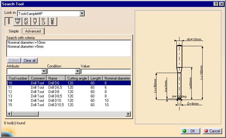
108
 Instantiation When Copying Display User Interface Allow you to customize.")
109 Operation This document explains how to customize machining operation settings for Machining products. Select the Operation tab, which is divided up into areas. Parameters in this area... Default Values After Creation or Machining Process (MP) Instantiation When Copying Display User Interface Allow you to customize... the use of default values what happens after creating machining operations or machining processes the duplication of geometry links tool path displays of operations dialog boxes of 3-axis surface machining operations. Default Values Select the checkbox if you want operations to be created with the values used in the current program. The values and units of attributes at the creation step of an operation are set to the values and units of the last edited and validated operation whatever its type (that is, exit the operation definition dialog box using OK). Otherwise the default settings delivered with the application are used. By default, this checkbox is selected. After Creation or Machining Process (MP) Instantiation Select the desired checkboxes to specify conditions to be applied when you create machining operations or machining processes. Sequence machining operation Machining operations are automatically sequenced in the current program after creation. Otherwise, sequencing can be managed in the feature view. Search compatible tool in previous operations When creating an operation, if a compatible tool exists in a previous operation of the current program, it will be set in the new operation. Otherwise, the operation will be incomplete.
110 Use a default tool When creating an operation, a search is done in the document to find a compatible tool. If no compatible tool exists, a default one is created in the document and set in the created operation. If checkbox is not selected, no tool will be defined on the operation. Start edit mode (not available for machining processes) When creating a machining operation, Edit mode is automatically started to allow modifying parameters of the created operation. Otherwise, the operation is added to the program but the machining operation editor is not started. By default, these checkboxes are selected. When Copying Select the checkbox if you want geometry links to be duplicated in a copied operation. Otherwise the geometry must be defined for the copied operation. Performance is improved when this checkbox is not selected. By default, this checkbox is selected. Display Select the checkbox if you want to display tool paths of operations in the current Part Operation. By default, this checkbox is not selected. User Interface Select the checkbox if you want to have the possibility of simplifying the dialog boxes of machining operations (that is, you can display the minimum number of parameters necessary for a correct tool path). This setting is available for 3-axis surface machining operations only. By default, this checkbox is not selected.
111 Output This document explains how to customize data output settings for Machining products. Select the Output tab, which is divided up into areas. Parameters in this area... Post Processor Tool Path Storage Tool Path Edition During Tool Path Computation Tool Output Point Tool Output Files... Location Allow you to customize... the type of PP files to be used for generating NC code output and the path where these files are located the tool path storage capability the tool path edition capability contact point storage type of tool output point default paths for NC output files storage. Post Processor Select the desired Processor option: None: no Post Processor is defined. NC code output is not possible in this case Cenit: you can choose from among the Post Processor parameter files proposed by Cenit to generate your NC code IMS: you can choose from among the Post Processor parameter files proposed by Intelligent Manufacturing Software (IMS) to generate your NC code ICAM: you can choose from among the Post Processor parameter files proposed by ICAM Technologies Corporation (ICAM) to generate your NC code. Enter the path of the folder containing Post processors. You can choose a folder by clicking the [...] button. File concatenation is possible. By default, the None option is selected. Tool Path Storage
112 Select the desired option to store tool path data either in the current document or in an external file (as a tpl file). For operations with large tool paths (more than points), tool path storage in an external file is recommended. By default, the Store tool path in the current document option is selected. Tool Path Edition Select the checkbox if you want to be able to edit tool paths even when the operation is locked. This capability is available only for activities with a tool path node in the specification tree. By default, this checkbox is selected. During Tool Path Computation Select the checkbox if you want to store contact points in the tool path. Performance is improved when this checkbox is not selected. By default, this checkbox is selected. Tool Output Point Select the desired option to select one of the following as output point: tool tip tool center point tool center point for ball end tools (that is, any tool with the Ball-end tool attribute selected or an end mill whose nominal diameter is equal to twice the corner radius). Performance is better when the Tool Tip option is selected. By default, the Tool Tip option is selected. Default File Locations

113 Specify default locations for storing Tool Path files, NC Documentation, and NC Code output. You can store tool paths files (tpl files) in the same folder as the CATProcess by selecting the checkbox. This allows you to store these files according to your CATProcess context. Otherwise, you can choose another location by clicking the [...] button. For NC Documentation, and NC Code output you can choose a folder easily by clicking the [...] button. You can customize the extension to be used for NC Code output (by default, the suffix used is CATNCCode). By default, the Tool path: Store at same location as the CATProcess checkbox is not selected.
 is accessible in Read/Write.")
114 Program This document explains how to customize manufacturing program settings for Machining products. Select the Program tab to customize program auto-sequencing rules and priorities. These settings are mainly intended for the administrator. Make sure that the document in the sequencing rules path (AllSequencingRules.CATProduct in the example below) is accessible in Read/Write. Auto Sequencing Access to sequencing rules settings Select the Access to sequencing rules settings checkbox to authorize user access to sequencing rules. You can then specify the path for the rules base You can choose a rules base easily by clicking the [...] button. By default, this checkbox is selected. Display sequencing rules and priorities Select the Display sequencing rules and priorities checkbox to authorize the display of sequencing rules and priorities in the user's view. In this case two more checkboxes can be selected in order to: allow the user to filter rules allow the user to modify rule priorities. By default, these checkboxes are selected.

115 Photo/Video This document explains how to customize material removal simulation settings for NC Manufacturing products. Select the Photo/Video tab, which is divided up into areas. Parameters in this area... Simulation at Video Photo Performance Color Positioning Move Allow you to customize... material removal simulation at program of Part Operation level Video material removal simulation options Photo material removal simulation options settings that influence performance color during material removal simulation allowed tool axis variation between two operations Simulation at Select the desired option to perform material removal simulation at either Program or Part Operation level. Depending on the selected level, simulation begins either from the start of the manufacturing program or from the start of the Part Operation. Best performance is obtained with Program level. By default, the Program level option is selected. Video Stop at tool change Select the Stop at tool change checkbox if you want the Video simulation to stop each time a tool change is encountered in the program. By default, this checkbox is not selected. Collision detection Select the desired Collisions detection option to: ignore collisions during the Video simulation
116 stop the Video simulation at the first collision continue the Video simulation even when collisions are detected. In this case, you can consult the list of collisions at any time during the simulation. Best performance is obtained when collisions are ignored. By default, the Ignore option is selected. Touch is collision Select the Touch is collision checkbox if you want touch (or contact) type of collision to be detected. By default, this checkbox is selected. Multiple Video result on program Select the Multiple Video result on program checkbox if you want to store video results on more than one operation in the program. By default, this checkbox is not selected. Photo Select the desired Fault box type for examining remaining material or gouges: Transparent: to display a transparent bounding box Wireframe: to display a wireframe bounding box None: if no bounding box is required. Best performance is obtained when no bounding box is required and the checkbox is not selected. By default, the Wireframe option is selected. Select the checkbox to compute all information at picked point. By default, this checkbox is not selected. Best performance is obtained when Fault box: None is selected and the checkbox is not selected. Performance
.")
117 Tool and faceting There are three methods of tool faceting used in Video simulation: Standard, Smaller and Larger. The number of facets for a tool representation is determined by the chord deviation that is set for the tool diameter (0.005% of the tool diameter). Smaller: The picture shows a rough approximation of a tool with six facets. Note that the chord deviation is always inside the actual circle, and that the points are always on the circle (accurate). This is the most accurate method for the Arc through Three Points command. Standard: The picture shows a rough approximation of a tool with six facets. Note that the chord deviation is partly inside and partly outside the actual circle, and that the points are not always on the circle. This is the best method for material removal simulation. However, this is not suitable for the Arc through Three Points command. Larger: The picture shows a rough approximation of a tool with six facets. Note that the chord deviation is outside the actual circle, and that the points are not on the circle.
118 This is not suitable for the Arc through Three Points command. However, it can be useful for gouge detection. By default, the Standard option is selected. Photo resolution Best performance is obtained when the Photo resolution is set to 0. In this case, a detailed simulation of a portion of the part can be obtained using the Closeup command. Increasing the resolution improves machining accuracy and gives a very detailed simulation. However, this requires increased memory and computation time. By default, this resolution is set to 0. Tool axis interpolation angle (5-axis only) Specify the maximum angle that the tool axis is allowed to vary between two consecutive points. Best performance is obtained for an angle of 10 degrees. Decreasing the angle improves the precision of the simulation. However, this requires increased memory and computation time. By default, this angle is set to 1degree. Optimized rendering for Video Set the Optimized rendering for Video checkbox to obtain an optimized rendering that improves Video simulation performance. Otherwise, more realistic colors are obtained with a slightly degraded performance. Milling, drilling, and turning operations are supported. By default, this checkbox is selected. Color

119 Set the tool (and associated machined area) color to be the same as or different from the last tool, or have different colors for all tools. Best performance is obtained with same colored tools. By default, the All different option is selected. Assign colors to the different tools using the associated color combo. Assign colors to tool holders, parts, and fixtures using the associated color combos. Positioning Move Set the Maximum tool axis variation that is to be allowed between the end point of an operation and the start point of the next operation. If the tool axis varies by an amount greater than the specified value, then the tool is positioned at the start of the following operation. By default, this angle is set to 1degree.
120 Reference Information Reference information that is specific to the Lathe Machining product can be found in this section. Rough Turning Operations Recess Turning Operations Groove Turning Operations Profile Finish Turning Operations Groove Finish Turning Operations Ramp Rough Turning Operations Ramp Recess Turning Operations Thread Turning Operations Sequential Turning Operations Lathe Tool Assembly Conventions Essential reference information on the following topics is provided in the NC Manufacturing Infrastructure User's Guide. NC Manufacturing Resources NC Macros PP Tables and PP Word Syntaxes Feeds and Speeds APT Formats CLfile Formats
121 Rough Turning Operations The information in this section will help you create and edit Rough Turning operations in your manufacturing program. The Rough Turning operation allows you to specify: Longitudinal, Face and Parallel Contour roughing modes external, internal or frontal machining according to the type of area to machine relimitation of the area to machine various approach and retract path types various lead-in and lift-off options with specific feedrates recess machining various contouring options with specific feedrates. The following topics are dealt with in the paragraphs below: Tools Geometry including Part and Stock Offsets Location and Limits Machining Strategy Parameters Feeds and Speeds Tool Compensation Macros. Tools for Rough Turning The following tools may be used: External and Internal tools with all insert types except groove and thread. External and Internal Groove tools with groove inserts. Geometry for Rough Turning Part and Stock profiles are required. They can be specified as follows: select edges either directly or after selecting the By Curve contextual command. In this case the Edge Selection toolbar appears to help you specify the guiding contour. select the Sectioning contextual command. Please refer to Sectioning for details of how to use this capability. Please note that the sectioning selection method is not associative. The End Limit option allows you to specify a point, line, curve or face to relimit or extrapolate the selected part profile. If a face is specified, the end element is the intersection of the face and the working plane. The position of the end of machining is defined with respect to this element by one of the following settings: None / In / On / Out. Relimiting the area to machine by means of limit elements If you specify a point, it is projected onto the part profile. A line through the projected point parallel to the radial axis delimits the area to machine. If you specify a line, its intersection with the part profile is calculated (if necessary, the line is extrapolated). A line through the intersection point parallel to the radial axis delimits the area to machine.
122 If you specify a curve, its intersection with the part profile is calculated (if necessary, the curve is extrapolated using the tangent at the curve extremity). A line through the intersection point parallel to the radial axis delimits the area to machine. Orientation for Rough Turning The following Orientations are proposed: Internal, External and Frontal (for Face and Parallel Contour Rough Turning only). The selected Orientation defines the type of geometric relimitation to be done between the stock and part geometry in order to determine the area to machine. Selected part and stock profiles do not need to be joined (see the following figures). External Rough Turning Internal Rough Turning Frontal Rough Turning
123 Frontal machining is proposed for face Rough Turning. In that case, the minimum and maximum diameters of the area to machine are determined by the stock profile dimensions. For example, in the following figure the area to machine is relimited by the spindle axis because the stock profile is also relimited by the spindle axis. Part and Stock Offsets for Rough Turning Stock offset: specifies a virtual displacement of the stock profile. Part offset: specifies a virtual displacement of the part profile. Axial part offset: specifies a virtual displacement of the part profile along the spindle axis direction.
124 Radial part offset: specifies a virtual displacement of the part profile in the radial axis direction. End limit offset: distance with respect to the end element (only if end element is a line or a curve, and when In or Out is set for end element positioning). Offsets can be positive or negative with any absolute value. The global offset applied to the part profile is the resulting value of the normal, axial and radial offsets. Location and Limits for Rough Turning The following machining Locations are proposed: Front, the part is machined toward the head stock Back, the part is machined from the head stock.
125 Orientation and Location settings determine the way the program closes the area to machine using radial, axial, axialradial or radial-axial relimitation. The following options allow you to restrict the area to machine that is pre-defined by the stock and part. You may want to restrict this area due to the physical characteristics of the tool and the type of machining to be done. Minimum Machining Radius Maximum Machining Radius (for internal machining)
126 Note that Max Boring Depth is defined on the tool. Axial Limit for Chuck Jaws (for external or frontal machining): Offset defined from the machining axis system. Machining Strategy Parameters for Rough Turning Path Definition for Rough Turning Machining tolerance Max Depth of Cut This option is used to specify the maximum distance between passes. It is replaced by Radial Depth of Cut and Axial Depth of Cut for Parallel Contour Rough Turning. Leading and Trailing Safety Angles The insert geometry is taken into account to avoid collision by reducing the maximum slope on which the tool can machine. The Leading Safety Angle and Trailing Safety Angle allow you to further reduce this slope. Note that Trailing Angle can be used only when Recess Machining is set. Leading and trailing angles can also be defined on the tool to define the maximum slope on which the tool can machine. In this case, the angles that reduce the slope the most will be taken into account. Part Contouring You can specify a contouring type for longitudinal and face Rough Turning in order to clear the part profile by means of the following settings: No: no contouring Each path: profile following at each roughing pass Last path only: profile following at last roughing pass only. Under Spindle Axis Machining For Face and Parallel Contour Rough Turning with Frontal machining, this option allows you to request machining under the spindle axis. Machining Direction (only for Parallel Contour and Face Rough Turning with Frontal machining) You can specify the machining direction with respect to the spindle axis by means of the To/From Spindle Axis choice. Recess Machining (if Contouring Type is Each Pass or Last Path Only) If you require recess machining, activate this checkbox. When recess machining is active in Parallel Contour Rough Turning, Axial and Radial Depth of Cut must have suitable values to ensure a collision free toolpath. See Recommendations below.
127 The following options are proposed for recess machining: Plunge Distance and Plunge Angle (for longitudinal and face Rough Turning) Define the plunge vector before each new pass with respect to the cutting direction. Example of Recess with External Longitudinal Rough Turning In the figure above the tool motion is as follows: approach in RAPID mode lead-in at the first recess pass and plunge approach for other passes plunge at plunge feedrate machine at machining feedrate contouring at contouring feedrate lift-off at last recess pass at lift-off feedrate. Note that Trailing angle is defined on the tool. Recommendations for Collision Free Recess Machining in Parallel Contour Rough Turning Machining in Parallel Contour Rough Turning is done by means of successive offsets of the toolpath: the offset depends on the axial and radial depth of cut values. The following recommendations describe how to set the axial and radial depth of cuts to ensure a collision free toolpath. Parallel contour principle: The parallel contours of the toolpath are obtained by first shifting the last pass then shifting each successive pass depending on the axial and radial depth of cut values.
128 Then the passes are relimited taking into account the stock definition. Correct combination of axial and radial depth of cuts Compared with the left and right angles on the insert, the axial and radial depth of cut values define a shift direction that must be compatible with the insert. The shift direction must be inside the limit angles defined on the tool insert otherwise a collision may occur. In collision cases, the collision is on the first pass, not on the last passes of the toolpath. Example of a correct combination
129 Example of an incorrect combination (right of tool) The parallel contour toolpath is in collision because the shift does not respect the tool insert angle on the right side. Lead-in, Lift-off and Attack for Rough Turning These options allow penetration into the workpiece at a reduced feedrate in order to prevent tool damage. Once the attack distance has been run through, the tool moves at machining feedrate. Lead-in Distance Defined with respect to the cutting direction and the stock profile with a stock clearance. The tool is in RAPID mode before this distance.
130 Lead-in Angle. If no lead-in angle is requested, lead-in path is parallel to the machining direction. For Longitudinal and Face Rough Turning the Lead-in Angle can be applied as follows: no angle applied to lead-in path lead-in angle applied to each path lead-in angle applied to last path only. Attack Distance Defined with respect to the cutting direction and the stock profile with a stock clearance. Lift-off Distance and Lift-off Angle Define the lift-off vector at the end of each new pass with respect to the cutting direction. For Longitudinal or Face Rough Turning, lift-off occurs: at the end of each pass when Contouring Type is set to None or Last Path Only. At the end of the last pass of the operation when the contouring type is set to Each Path. This prevents the tool from damaging the part when returning to the end point in RAPID mode.
131 at the end of each pass that ends on the stock profile. For Parallel Contour Rough Turning, lift-off occurs when the end of the pass has already been machined by a previous pass. Feeds and Speeds for Rough Turning Speed unit can be set to: Angular: spindle speed in revolutions per minute Linear: constant cutting speed in units per minute then you can give a Machining Speed value. Available feedrates in units per revolution are as follows: Machining Feedrate Lead-in Feedrate which is applied during the lead-in and attack distance Lift-off Feedrate Contouring Feedrate (if contouring type is Each Path or Last Path Only) Plunge Feedrate (for longitudinal and face Rough Turning). Feedrates in units per minute are also available for air cutting such as macro motions and path transitions. Note that RAPID feedrate can be replaced by Air Cutting feedrate in tool trajectories (except in macros) by selecting the checkbox in the Feed and Speeds tab page. Dwell setting indicates whether the tool dwell at the end of each path is to be set in seconds or a number of spindle revolutions. Please note that decimal values can be used for the number of revolutions. For example, when machining big parts that have a large volume, it can be useful to specify a dwell using a value of less than one revolution (0.25, for example). Tool Compensation for Rough Turning You can select a tool compensation number corresponding to the desired tool output point. Note that the usable compensation numbers are defined on the tool assembly linked to the machining operation. If you do not select a tool compensation number, the output point corresponding to type P9 will be used by default. Approach and Retract Macros for Rough Turning The following Approach and Retract macros are proposed: direct, axial-radial, radial-axial. The selected type (approach or retract) defines the tool motion before or after machining: the tool moves in RAPID mode during the approach or retract.
132 Linking macros, which comprise retract and approach motion can also be used on Rough Turning operations. Approach and retract linking motions are interruptible. It can be useful to interrupt an operation when the foreseeable lifetime of the insert is not long enough to complete the machining. See Define Macros on a Turning Operation for more information.
133 Recess Turning Operations The information in this section will help you create and edit Recess Turning operations in your manufacturing program. The Recess Turning operation allows you to machine a recess by means of a One Way, Zig Zag or Parallel Contour tool motion. You can specify: external, internal, frontal or inclined machining according to the type of area to machine various approach and retract path types various lead-in and lift-off options with specific feedrates part contouring tool output point change. The following topics are dealt with in the paragraphs below: Tools Geometry Machining Strategy Parameters Feeds and Speeds Tool Compensation
134 Macros. Tools for Recess Turning The following tools may be used: External and Internal tools with all insert types except groove and thread. Internal, External and Frontal Groove tools with groove inserts. Geometry for Recess Turning Part and Stock profiles are required. They can be specified as follows: select edges either directly or after selecting the By Curve contextual command. In this case the Edge Selection toolbar appears to help you specify the guiding contour. select the Sectioning contextual command. Please refer to Sectioning for details of how to use this capability. Please note that the sectioning selection method is not associative. Orientation for Recess Turning The following Orientations are proposed: internal, external, frontal and inclined. The selected Orientation defines the type of geometric relimitation to be done between the stock and part geometry in order to determine the area to machine. For an inclined orientation you must specify the Angle of Incline. Part and Stock Offsets for Recess Turning Stock offset, which is defined perpendicular to the stock profile Part offset, which is defined perpendicular to the part profile. Axial part offset Radial part offset. Offsets can be positive or negative with any absolute value. The global offset applied to the part profile is the resulting value of the normal, axial and radial offsets. Machining Strategy Parameters for Recess Turning Path Definition for Recess Turning Recess Turning Mode: One Way, Zig Zag or Parallel Contour Max Depth of Cut This option is used to specify the maximum distance between passes. Axial and Radial Depth of Cut These options are used to specify the maximum axial and radial distances between passes for Parallel
135 Contour mode. Machining Tolerance Machining Direction For Zig Zag tool motion, you must specify a first cutting direction as follows: To or From Head Stock for Internal and External machining To or From Spindle for Frontal machining To Right or Left of Recess for Inclined machining When a part profile has multiple recesses (that is, a non-convex profile along the cutting direction), only the first recess along the specified direction is machined. Leading and Trailing Safety Angles for One way and Parallel Contour modes The insert geometry is taken into account to avoid collision by reducing the maximum slope on which the tool can machine. The Leading and Trailing Safety Angles allow you to further reduce this slope. Note that leading and trailing angles can also be defined on the tool to define the maximum slope on which the tool can machine. In this case, the angles that reduce the slope the most will be taken into account. Gouging Safety Angle (for Zig Zag mode only) Angles of the insert are taken into account to avoid collision by reducing the maximum slope on which the tool can machine. The Gouging Safety Angle allows you to further reduce this slope. Note that a gouging angle can also be defined on the tool to define the maximum slope on which the tool can machine. In this case, the angle that reduces the slope the most will be taken into account. Under Spindle Axis Machining For Frontal or Inclined machining, this option allows you to request machining under the spindle axis. Part Contouring You can specify if contouring is required by means of the proposed checkbox. The part profile is followed at the end of Recess Turning. This is done by machining down the sides of the recess in order to clear the profile. Lead-in, Lift-off and Attack for Recess Turning
136 Lead-in Distance Defined with respect to the cutting direction and the stock profile with a stock clearance. The tool is in RAPID mode before this distance. Attack Distance Defined with respect to the cutting direction and the stock profile with a stock clearance. Angle and Distance before Plunge Define the plunge vector before each new pass with respect to the cutting direction. Lift-off Distance and Lift-off Angle Define the lift-off vector at the end of the last pass with respect to the cutting direction. Example of one-way Recess Turning. Note that Trailing angle is defined on the tool. In the figure above the tool motion is as follows: approach in RAPID mode lead-in at the first recess pass and plunge approach for other passes plunge at plunge feedrate machine at machining feedrate contouring at contouring feedrate lift-off at last recess pass at lift-off feedrate. Feeds and Speeds for Recess Turning
137 Speed unit can be set to: Angular: spindle speed in revolutions per minute Linear: constant cutting speed in units per minute then you can give a Machining Speed value. Available feedrates in units per revolution are as follows: Machining Feedrate Lead-in Feedrate, which is applied during the lead-in and attack distance. Lift-off Feedrate Contouring Feedrate Plunge Feedrate. Feedrates in units per minute are also available for air cutting such as macro motions and path transitions. Note that RAPID feedrate can be replaced by Air Cutting feedrate in tool trajectories (except in macros) by selecting the checkbox in the Feed and Speeds tab page. Dwell setting indicates whether the tool dwell at the end of each path is to be set in seconds or a number of spindle revolutions. Please note that decimal values can be used for the number of revolutions. For example, when machining big parts that have a large volume, it can be useful to specify a dwell using a value of less than one revolution (0.25, for example). Tool Compensation for Recess Turning You can select a tool compensation number corresponding to the desired tool output point. Note that the usable compensation numbers are defined on the tool assembly linked to the machining operation. If you do not select a tool compensation number, the output point corresponding to type P9 will be used by default. Note that the change of output point is managed automatically if you set the Change Output Point option. If the output point is consistent with the flank of the recess to be machined, the output point is changed when the other flank of the recess is machined. At the end of the operation, the output point is the same as it was at the start of the operation. See Changing the Output Point for more information. Approach and Retract Macros for Recess Turning The following Approach and Retract macros are proposed: direct, axial-radial, radial-axial. The selected type (approach or retract) defines the tool motion before or after machining: the tool moves in RAPID mode during the approach or retract.
138 Linking macros, which comprise retract and approach motion can also be used on roughing operations. Approach and retract linking motions are interruptible. It can be useful to interrupt an operation when the foreseeable lifetime of the insert is not long enough to complete the machining. See Define Macros on a Turning Operation for more information.
139 Groove Turning Operations The information in this section will help you create and edit Groove Turning operations in your manufacturing program. The Groove Turning operation allows you to machine a groove by a series of plunging cuts. You can specify: external, internal, frontal or inclined machining according to the type of area to machine various approach and retract path types various lead-in and lift-off options with specific feedrates various plunge locations tool output point change. The following topics are dealt with in the paragraphs below: Tools Geometry Machining Strategy Parameters Feeds and Speeds Tool Compensation Macros. Tools for Groove Turning The following tools may be used: Internal, External and Frontal Groove tools with groove inserts. External and Internal tools with round inserts. Geometry for Groove Turning Part and Stock profiles are required. They can be specified as follows: select edges either directly or after selecting the By Curve contextual command. In this case the Edge Selection toolbar appears to help you specify the guiding contour. select the Sectioning contextual command. Please refer to Sectioning for details of how to use this capability. Please note that the sectioning selection method is not associative. Orientation for Groove Turning The following Orientations are proposed: internal, external, frontal and inclined. The selected Orientation defines the type of geometric relimitation to be done between the stock and part geometry in order to
140 determine the area to machine. For an inclined orientation you must specify the Angle of Incline. Part and Stock Offsets for Groove Turning Stock offset, which is defined perpendicular to the stock profile Part offset, which is defined perpendicular to the part profile. Axial part offset Radial part offset. Offsets can be positive or negative with any absolute value. The global offset applied to the part profile is the resulting value of the normal, axial and radial offsets. Machining Strategy Parameters for Groove Turning Path Definition for Groove Turning Max Depth of Cut This option is used to specify the maximum distance between plunges. First Plunge You must specify a first plunge position according to the groove orientation by means of the following choice: Left/Down - Center - Right/Up - Automatic. Automatic is only available for frontal machining. In this case, the position of the first plunge is deduced from the tool's minimum and maximum cut diameters. The position is at a distance: (Minimum cut radius + Maximum cut radius)/2. Next Plunges (if First Plunge is set to Center). You can specify the position of the plunges that follow the first plunge with respect to: the spindle axis by means of the To or From Spindle for frontal machining the head stock by means of the To or From Head Stock for internal or external machining the groove by means of Left or Right of Groove for Inclined machining. Part Contouring You can specify if contouring is required by means of the proposed checkbox. The part profile is followed at the end of grooving. This is done by machining down the sides of the groove in order to clear the profile. Grooving by Level mode This option allows you to machine the groove in one or more level. Multiple-levels mode is particularly useful when the groove is too deep to machine in one level. In this case Maximum grooving depth defines the maximum depth of each level. If it is greater than the Maximum Depth of Cut defined on the tool, the value on the tool is taken into account. Under Spindle Axis Machining When Groove Turning in frontal mode, this option allows you to request machining under the spindle axis. Chip Break You can specify if chip clearing is to be done during machining by setting the check box. In this case you must specify Plunge, Retract and Clear distances. Gouging Safety Angle Angles of the grooving insert are taken into account to avoid collision by reducing the maximum slope on which the tool can machine. The Gouging Safety Angle allows you to further reduce this slope. Note that a gouging angle can also be defined on the tool to define the maximum slope on which the tool can machine. In this case, the angle that reduces the slope the most will be taken into account.
141 Machining Tolerance. Lead-in, Lift-off and Attack for Groove Turning Lead-in Distance Defined with respect to the cutting direction and the stock profile with a stock clearance. The tool is in RAPID mode before this distance. Attack Distance Defined with respect to the cutting direction and the stock profile with a stock clearance. These options allow penetration into the workpiece at a reduced feedrate in order to prevent tool damage. Once the attack distance has been run through, the tool moves at machining feedrate. When tool motion between two passes is in contact with the part profile, in order to avoid collisions the corresponding feed is the lift-off feedrate and not RAPID. Lift-off Distance and Lift-off Angle Define the lift-off vector at the end of each new pass with respect to the cutting direction. Feeds and Speeds for Groove Turning Speed unit can be set to: Angular: spindle speed in revolutions per minute Linear: constant cutting speed in units per minute then you can give a Machining Speed value. Available feedrates in units per revolution are as follows: Contouring Feedrate Lead-in Feedrate, which is applied during lead-in and attack distances Lift-off Feedrate First Plunge Feedrate and Next Plunges Feedrate. Different feedrates can be assigned to the first plunge and the following plunges. Feedrates in units per minute are also available for air cutting such as macro motions and path transitions. Note that RAPID feedrate can be replaced by Air Cutting feedrate in tool trajectories (except in macros) by selecting the checkbox in the Feed and Speeds tab page. Dwell setting indicates whether the tool dwell at the end of a path or a plunge is to be set in seconds or a number of spindle revolutions. Please note that decimal values can be used for the number of revolutions. For example, when machining big parts that have a large volume, it can be useful to specify a dwell using a value of less than one revolution (0.25, for example).
142 Tool Compensation for Groove Turning You can select a tool compensation number corresponding to the desired tool output point. Note that the usable compensation numbers are defined on the tool assembly linked to the machining operation. If you do not select a tool compensation number, the output point corresponding to type P9 will be used by default. Note that the change of output point is managed automatically if you set the Change Output Point option. If the output point is consistent with the flank of the groove to be machined, the output point is changed when the other flank of the groove is machined. At the end of the operation, the output point is the same as it was at the start of the operation. See Changing the Output Point for more information. Approach and Retract Macros for Groove Turning The following Approach and Retract macros are proposed: direct, axial-radial, radial-axial. The selected type (approach or retract) defines the tool motion before or after machining: the tool moves in RAPID mode during the approach or retract. Linking macros, which comprise retract and approach motion can also be used on roughing operations. Approach and retract linking motions are interruptible. It can be useful to interrupt an operation when the foreseeable lifetime of the insert is not long enough to complete the machining. See Define Macros on a Turning Operation for more information.
143 Profile Finish Turning Operations The information in this section will help you create and edit Profile Finish Turning operations in your manufacturing program. The Profile Finish Turning operation allows you to finish a part profile. You can specify: the type of machining according to the profile of the area to machine (external, internal or frontal) relimitation of the profile by start and end elements various approach and retract path types linear and circular lead-in and lift-off options with specific feedrates recess machining various corner processing options cutter compensation. The following topics are dealt with in the paragraphs below: Tools Geometry Machining Strategy Parameters Feeds and Speeds Tool Compensation Macros. Tools for Profile Finish Turning The following tools may be used: External and Internal tools with all insert types except groove and thread. External and Internal Groove tools with groove inserts. Geometry for Profile Finish Turning A Part profile is required. It can be specified as follows: select edges either directly or after selecting the By Curve contextual command. In this case the Edge Selection toolbar appears to help you specify the guiding contour. select the Sectioning contextual command. Please refer to Sectioning for details of how to use this capability. Please note that the sectioning selection method is not associative. Start Limit: None / In / On / Out This option allows you to specify a point, line, curve or face as the start element of the part profile. If a face is specified, the start element is the intersection of the face and the working plane. The position of the start of machining is also defined with respect to this element. In / On / Out: allows you to specify the Go-Go type positioning of the tool with respect to the start element.
144 The On option is always used for a point type start element. If needed, the profile may be extrapolated to the start element. End Limit: None / In / On / Out This option allows you to specify a point, line, curve or face as the end element of the part profile. If a face is specified, the end element is the intersection of the face and the working plane. The position of the end of machining is also defined with respect to this element. In / On / Out: allows you to specify the Go-Go type positioning of the tool with respect to the end element. The On option is always used for a point type end element. Relimiting the area to machine by means of limit elements If you specify a point, it is projected onto the part profile. A line through the projected point parallel to the radial axis delimits the area to machine. If you specify a line, its intersection with the part profile is calculated (if necessary, the line is extrapolated). A line through the intersection point parallel to the radial axis delimits the area to machine. If you specify a curve, its intersection with the part profile is calculated (if necessary, the curve is extrapolated using the tangent at the curve extremity). A line through the intersection point parallel to the radial axis delimits the area to machine. If needed, the profile may be extrapolated to the end element. The figure above illustrates the use of start and end elements for Profile Finish Turning. Profile is machined from start element. Profile is extrapolated up to end element. Direct approach and radial-axial retract. Orientation and Location for Profile Finish Turning Orientation: Internal / External / Frontal This option allows you to specify the type of machining according to the location of the area to machine on the part. Location: Front, the profile is machined toward the head stock Back, the profile is machined from the head stock.
145 Corner Processing for Profile Finish Turning The following options allow you to define how corners of the profile are to be machined: None: no corners are to be machined along the profile Chamfer: only 90 degree corners of the profile are chamfered Rounded: all corners of the profile are rounded. Corner processing options are also available to define how the entry and exit corners are to be machined. Entry and exit corners are defined by either a chamfer length, or a corner radius and corner angle. Part Offsets for Profile Finish Turning Part offset, which is defined perpendicular to the part profile. Axial part offset. Radial part offset. Start limit offset: distance with respect to the start element (only if start element is a line or a curve, and when In or Out is set for start element positioning).
146 End limit offset: distance with respect to the end element (only if end element is a line or a curve, and when In or Out is set for end element positioning). Offsets can be positive or negative with any absolute value. The global offset applied to the part profile is the resulting value of the normal, axial and radial offsets. In addition to these global values, local offsets can be applied to segments, curves and arcs of the part profile. Machining Strategy Parameters for Profile Finish Turning Path Definition for Profile Finish Turning Machining Direction: To or From Spindle This option is only available for frontal machining for specifying the machining direction with respect to the spindle axis. If start and end elements are defined that are in conflict with the machining direction, then these elements will be reversed automatically. Contouring for Outside Corners: Angular / Circular Allows you to define whether angular or circular contouring is to be applied to corners of the profile (only if corner processing is set to Rounded or Chamfer). Under Spindle Axis Machining When finishing in frontal mode, this option allows you to request machining under the spindle axis. Recess Machining When this option is set, a recess machining path is done after the profile finish path. The trailing safety angle option becomes available. Leading and Trailing Safety Angles The insert geometry is taken into account to avoid collision by reducing the maximum slope on which the tool can machine. The Leading Safety Angle and Trailing Safety Angle allow you to further reduce this slope. Note that leading and trailing angles can also be defined on the tool to define the maximum slope on which
147 the tool can machine. In this case, the angles that reduce the slope the most will be taken into account. Machining Tolerance for following the profile. Lead-in and Lift-off for Profile Finish Turning Lead-in type: Linear / Circular Defines the type of lead-in onto the profile at lead-in feedrate Linear: lead-in up to the point where profile machining starts is defined by means of the lead-in distance and lead-in angle options. Circular: lead-in is circular and tangent to the point where profile machining starts. It is defined by means of the lead-in radius and lead-in angle options. Linear lead-in and circular lift-off (Profile Finish Turning) Lift-off type: Linear / Circular. Defines the type of lift-off from the profile at lift-off feedrate Linear: lift-off from the point where profile machining ends is defined by means of the lift-off distance and lift-off angle options. Circular: lift-off is circular and tangent from the point where profile machining ends. It is defined by means of the lift-off radius and lift-off angle options. In the example below, the round tool is tangent In start element plus clearance at start of profiling. Round tool is tangent Out end element plus clearance at end of profiling.
148 Local Invert Invert strategy None: no Invert Strategy Overlap: defined by a clearance and a overlap parameter. Thickness: defined by a clearance and a thickness parameter. Machine inverted elements first: you machine inverted elements the first path, and then the other elements. Lead-in Angle and Distance or Radius for entry path. Lift-off Angle and Distance or Radius for exit path. Lift-off type allows to select the type of entry and exit motion between Linear and Circular. Linear motion is defined by a distance and an angle. Circular motion is defined by a radius and an angle. Feeds and Speeds for Profile Finish Turning Speed unit can be set to: Angular: spindle speed in revolutions per minute Linear: constant cutting speed in units per minute then you can give a Machining Speed value. Available feedrates in units per revolution are as follows: Machining Feedrate Chamfering Feedrate for machining chamfers or corners Lift-off Feedrate
149 Lead-in Feedrate. In addition to these global feedrates, local feedrates can be applied to segments, curves and arcs of the part profile. Feedrates in units per minute are also available for air cutting such as macro motions and path transitions. Note that RAPID feedrate can be replaced by Air Cutting feedrate in tool trajectories (except in macros) by selecting the checkbox in the Feed and Speeds tab page. Tool Compensation for Profile Finish Turning You can select a tool compensation number corresponding to the desired tool output point. Note that the usable compensation numbers are defined on the tool assembly linked to the machining operation. If you do not select a tool compensation number, the output point corresponding to type P9 will be used by default. CUTCOM (Cutter Compensation): None / On / Reverse. If this option is set to On or Reverse, the NC output will include CUTCOM instructions in approach and retract paths for cutter compensation. On: CUTCOM/RIGHT instruction generated if tool is to the right of the toolpath and CUTCOM/LEFT if tool is to the left of the toolpath. Reverse: CUTCOM/RIGHT instruction generated if tool is to the left of the toolpath and CUTCOM/LEFT if tool is to the right of the toolpath. See Cutter Compensation with Finish Operations for more information. Approach and Retract Macros for Profile Finish Turning The following Approach and Retract macros are proposed: direct, axial-radial, radial-axial. The selected type (approach or retract) defines the tool motion before or after machining: the tool moves in RAPID mode during the approach or retract.
150 Groove Finish Turning Operations The information in this section will help you create and edit Groove Finish Turning operations in your manufacturing program. The Groove Finish Turning operation allows you to finish a groove by means of downward profile following. You can specify: the type of machining according to the groove profile to be machined (external, internal, frontal or inclined) relimitation of the profile by start and end elements various approach and retract path types linear and circular lead-in and lift-off options with specific feedrates various corner processing options with specific feedrates local feedrates for individual elements of the machined profile tool output point change cutter compensation. The following topics are dealt with in the paragraphs below: Tools Geometry Machining Strategy Parameters Feeds and Speeds Tool Compensation Macros. Tools for Groove Finish Turning The following tools may be used: Internal, External and Frontal Groove tools with groove inserts. External and Internal tools with round inserts. Geometry The Part profile (that is, the groove finish profile) is required. It can be specified as follows: select edges either directly or after selecting the By Curve contextual command. In this case the Edge Selection toolbar appears to help you specify the guiding contour. select the Sectioning contextual command. Please refer to Sectioning for details of how to use this capability. Please note that the sectioning selection method is not associative. Start Limit: None / In / On / Out This option allows you to specify a point, line, curve or face as the start element of the groove finish profile. The position of the start of machining is also defined with respect to this element. If a face is specified, the start
151 element is the intersection of the face and the working plane. If needed, the profile may be extrapolated to the start element. In / On / Out allows you to specify the Go-Go type positioning of the tool with respect to the start element. The On option is always used for a point type start element. End Limit: None / In / On / Out This option allows you to specify a point, line, curve or face as the end element of the groove finish profile. If a face is specified, the end element is the intersection of the face and the working plane. The position of the end of machining is also defined with respect to this element. If needed, the profile may be extrapolated to the end element. In / On / Out allows you to specify the Go-Go type positioning of the tool with respect to the end element. The On option is always used for a point type start element. Relimiting the area to machine by means of limit elements If you specify a point, it is projected onto the part profile. A line through the projected point parallel to the radial axis delimits the area to machine. If you specify a line, its intersection with the part profile is calculated (if necessary, the line is extrapolated). A line through the intersection point parallel to the radial axis delimits the area to machine. If you specify a curve, its intersection with the part profile is calculated (if necessary, the curve is extrapolated using the tangent at the curve extremity). A line through the intersection point parallel to the radial axis delimits the area to machine. Orientation for Groove Finish Turning Orientation: Internal / External / Frontal / Inclined This option allows you to define the orientation of the groove to be machined. For an inclined orientation you must specify the Angle of Incline. Corner Processing for Groove Finish Turning The following options allow you to define how corners of the profile are to be machined: Follow profile: no corners are to be machined along the profile Chamfer: only 90 degree corners of the profile are chamfered Rounded: all corners of the profile are rounded. Corner processing is proposed for Entry, Exit and Other corners. Chamfer Length if Other corner processing mode is Chamfer. Corner Radius if Other corner processing mode is Rounded. Entry Corner Chamfer Length on first flank of groove when Entry corner processing mode is Chamfer Entry Corner Radius on first flank of groove when Entry corner processing mode is Corner Entry Corner Angle on first flank of groove when Entry corner processing mode is Corner Exit Corner Chamfer Length on last flank of groove when Exit corner processing mode is Chamfer Exit Corner Radius on last flank of groove when Exit corner processing mode is Corner Exit Corner Angle on last flank of groove when Exit corner processing mode is Corner.
152 Part Offsets for Groove Finish Turning Part offset, which is defined perpendicular to the part profile. Axial part offset. Radial part offset. Start limit offset: distance with respect to the start element (only if start element is a line or a curve, and when In or Out is set for start element positioning). End limit offset: distance with respect to the end element (only if end element is a line or a curve, and when In or Out is set for end element positioning). Offsets can be positive or negative with any absolute value. The global offset applied to the part profile is the resulting value of the normal, axial and radial offsets. In addition to these global offsets, local values can be applied to segments, curves and arcs of the part profile. Machining Strategy Parameters for Groove Finish Turning Path Definition for Groove Finish Turning Machining Direction You can specify the machining direction by means of: To or From Head for Internal and External machining To or From Spindle for Frontal machining To Right or Left of Groove for Inclined machining If start and end elements are defined that are in conflict with the machining direction, then these elements will be reversed automatically. Clearance: this value defines the clearance to be applied to the next flank after the first machined flank. The bottom of the groove will be machined up to the position defined by this clearance value. Tool Overlap Distance on Groove Bottom. Under Spindle Axis Machining When finishing in frontal mode, this option allows you to request machining under the spindle axis. Contouring for Outside Corners: Angular / Circular Allows you to define whether an angle or circle contouring mode is to be applied to corners of the groove profile (only if corner processing is set to None or Chamfer). Machining Tolerance for following the groove finish profile. Lead-in for Groove Finish Turning First Flank Lead-in: Linear / Circular Defines the type of lead-in at lead-in feedrate on the first flank of the groove. Linear: lead-in up to the point where first flank machining starts is defined by means of the first lead-in distance and first lead-in angle options. Circular: lead-in is circular and tangent to the point where first flank machining starts. It is defined
153 by means of the first lead-in radius and first lead-in angle options. The example below shows Linear lead-in and Circular lift-off for Groove Finish Turning. Last Flank Lead-in: Linear / Circular Defines the type of lead-in at lead-in feedrate on the last flank of the groove. Linear: lead-in up to the point where last flank machining starts is defined by means of the last lead-in distance and last lead-in angle options. Circular: lead-in is circular and tangent to the point where last flank machining starts. It is defined by means of the last lead-in radius and last lead-in angle options. Other Flank Lead-in: Linear / Circular For a groove that has multiple recesses, this option defines the type of lead-in required to machine flanks other than the first and last flanks. Other Lead-in Distance on other flanks of the groove when other flank lead-in type is Linear Other Lead-in Angle on other flanks of the groove when other flank lead-in type is Linear or Circular Other Lead-in Radius on other flanks of the groove when other flank lead-in type is Circular.
154 Lift-off for Groove Finish Turning Lift-off Type: Linear / Circular Defines the type of lift-off from the groove at lift-off feedrate. Lift-off Distance when lift-off type is Linear. Lift-off Angle when lift-off type is Linear or Circular. Lift-off Radius when lift-off type is Circular. Feeds and Speeds for Groove Finish Turning Speed unit can be set to: Angular: spindle speed in revolutions per minute Linear: constant cutting speed in units per minute then you can give a Machining Speed value. Available feedrates in units per revolution are as follows: Machining Feedrate Chamfering Feedrate for machining chamfers or corners Lift-off Feedrate Lead-in Feedrate. In addition to these global feedrates, local feedrates can be applied to segments, curves and arcs of the part profile. Feedrates in units per minute are also available for air cutting such as macro motions and path transitions. Note that RAPID feedrate can be replaced by Air Cutting feedrate in tool trajectories (except in macros) by selecting the checkbox in the Feed and Speeds tab page. Tool Compensation for Groove Finish Turning You can select a tool compensation number corresponding to the desired tool output point. Note that the usable compensation numbers are defined on the tool assembly linked to the machining operation. If you do not select a tool compensation number, the output point corresponding to type P9 will be used by default. CUTCOM (Cutter Compensation): None / On / Reverse If this option is set to On or Reverse, the NC output will include CUTCOM instructions in approach and retract paths for cutter compensation. On: CUTCOM/RIGHT instruction generated if tool is to the right of the toolpath and CUTCOM/LEFT if tool is to the left of the toolpath. Reverse: CUTCOM/RIGHT instruction generated if tool is to the left of the toolpath and CUTCOM/LEFT if tool is to the right of the toolpath.
155 See Cutter Compensation with Finish Operations for more information. Note that the change of output point is managed automatically if you have set the Change Output Point option. If the output point is consistent with the flank of the groove to be machined, the output point is changed when the other flank of the groove is machined. At the end of the operation, the output point is the same as it was at the start of the operation. See Changing the Output Point for more information. Approach and Retract Macros for Groove Finishing The following Approach and Retract macros are proposed: direct, axial-radial, radial-axial. The selected type (approach or retract) defines the tool motion before or after machining: the tool moves in RAPID mode during the approach or retract.
156 Ramp Rough Turning Operations The information in this section will help you create and edit Ramp Rough Turning operations in your manufacturing program. This type of operation is suitable for machining hard materials using round ceramic inserts, thereby minimizing wear and cutting stress. The Ramp Rough Turning operation allows you to specify: Longitudinal and Face roughing modes external, internal or frontal machining according to the type of area to machine relimitation of the area to machine various approach and retract path types various lead-in and lift-off options with specific feedrates rework machining. The following topics are dealt with in the paragraphs below: Tools Geometry including Part and Stock Offsets Location and Limits Machining Strategy Parameters Feeds and Speeds Tool Compensation Macros. Tools for Ramp Rough Turning The following tools may be used: External and Internal tools with round inserts. Geometry for Ramp Rough Turning Part and Stock profiles are required. They can be specified as follows: select edges either directly or after selecting the By Curve contextual command. In this case the Edge Selection toolbar appears to help you specify the guiding contour. select the Sectioning contextual command. Please refer to Sectioning for details of how to use this capability. Please note that the sectioning selection method is not associative. The End Limit option allows you to specify a point, line, curve or face to relimit or extrapolate the selected part profile. If a face is specified, the end element is the intersection of the face and the working plane. The position of the end of machining is defined with respect to this element by one of the following settings: None / In / On / Out. Relimiting the area to machine by means of limit elements If you specify a point, it is projected onto the part profile. A line through the projected point parallel to the radial axis delimits the area to machine. If you specify a line, its intersection with the part profile is calculated (if necessary, the line is extrapolated). A line through the intersection point parallel to the radial axis delimits the area to machine.
157 If you specify a curve, its intersection with the part profile is calculated (if necessary, the curve is extrapolated using the tangent at the curve extremity). A line through the intersection point parallel to the radial axis delimits the area to machine. Orientation for Ramp Rough Turning The following Orientations are proposed: Internal, External and Frontal (for Face Roughing only). The selected Orientation defines the type of geometric relimitation to be done between the stock and part geometry in order to determine the area to machine. Selected part and stock profiles do not need to be joined (see the following figures). External Ramp Rough Turning Internal Ramp Rough Turning Frontal Ramp Rough Turning Frontal machining is proposed for face Ramp Rough Turning. In that case, the minimum and maximum diameters of the

158 area to machine are determined by the stock profile dimensions. For example, in the following figure the area to machine is relimited by the spindle axis because the stock profile is also relimited by the spindle axis. Part and Stock Offsets for Ramp Rough Turning Stock offset: specifies a virtual displacement of the stock profile. Part offset: specifies a virtual displacement of the part profile. Axial part offset: specifies a virtual displacement of the part profile along the spindle axis direction.
.")
159 Radial part offset: specifies a virtual displacement of the part profile in the radial axis direction. End limit offset: distance with respect to the end element (only if end element is a line or a curve, and when In or Out is set for end element positioning). Offsets can be positive or negative with any absolute value. The global offset applied to the part profile is the resulting value of the normal, axial and radial offsets. Location and Limits for Ramp Rough Turning The following machining Locations are proposed: Front, the part is machined toward the head stock Back, the part is machined from the head stock.
160 Orientation and Location settings determine the way the program closes the area to machine. The following options allow you to restrict the area to machine that is pre-defined by the stock and part. You may want to restrict this area due to the physical characteristics of the tool and the type of machining to be done. Minimum Machining Radius Maximum Machining Radius (for internal machining)
161 Note that Max Boring Depth is defined on the tool. Axial Limit for Chuck Jaws (for external or frontal machining): Offset defined from the machining axis system. Machining Strategy Parameters for Ramp Rough Turning Path Definition for Ramp Rough Turning Machining tolerance Max Depth of Cut This option is used to specify the maximum distance between passes. Under Spindle Axis Machining For Face Ramp Rough Turning, this option allows you to request machining under the spindle axis. Machining Direction (only for Face Roughing with Frontal machining) You can specify the machining direction with respect to the spindle axis by means of the To/From Spindle Axis choice. Start pass mode is defined by one of the following settings: Chamfer, Rounded, None. If Rework mode is set, the following options are available: Distance before Rework Plunge Angle before Rework Plunge. Lead-in and Lift-off for Ramp Rough Turning These options allow penetration into the workpiece at a reduced feedrate in order to prevent tool damage. Lead-in Distance Defined with respect to the cutting direction and the stock profile with a stock clearance. The tool is in RAPID mode before this distance. Lift-off Distance and Lift-off Angle Define the lift-off vector at the end of each new pass with respect to the cutting direction.
162 Feeds and Speeds for Ramp Rough Turning Speed unit can be set to: Angular: spindle speed in revolutions per minute Linear: constant cutting speed in units per minute then you can give a Machining Speed value. Available feedrates in units per revolution are as follows: Machining Lead-in Lift-off Plunge Light loading Air cutting. Feedrates in units per minute are also available for air cutting (for example, during macro motions and path transitions). Note that RAPID feedrate can be replaced by Air Cutting feedrate in tool trajectories (except in macros) by selecting the checkbox in the Feed and Speeds tab page. Dwell setting indicates whether the tool dwell at the end of each path is to be set in seconds or a number of spindle revolutions. Please note that decimal values can be used for the number of revolutions. For example, when machining big parts that have a large volume, it can be useful to specify a dwell using a value of less than one revolution (0.25, for example). Tool Compensation for Ramp Rough Turning You can select a tool compensation number corresponding to the desired tool output point. Note that the usable compensation numbers are defined on the tool assembly linked to the machining operation. If you do not select a tool compensation number, the output point corresponding to type P9 will be used by default. Approach and Retract Macro Motions for Ramp Rough Turning The following predefined Approach and Retract motions are proposed: direct, axial-radial, radial-axial. The selected type
163 (approach or retract) defines the tool motion before or after machining. Linking macros, which comprise retract and approach motion can also be used on roughing operations. Approach and retract linking motions are interruptible. It can be useful to interrupt an operation when the foreseeable lifetime of the insert is not long enough to complete the machining. You can also build your own macros from elementary paths. See Define Macros on a Turning Operation for more information.
164 Ramp Recess Turning Operations The information in this section will help you create and edit Ramp Recess Turning operations in your manufacturing program. This type of operation is suitable for machining hard materials using round ceramic inserts, thereby minimizing wear and cutting stress. The Ramp Recess Turning operation allows you to machine a recess by means of a One Way or Zig Zag tool motion. You can specify: external, internal, frontal or inclined machining according to the type of area to machine various approach and retract path types various plunge and lift-off options with specific feedrates part contouring rework tool output point change. The following topics are dealt with in the paragraphs below: Tools Geometry Machining Strategy Parameters Feeds and Speeds Tool Compensation Macros. Tools for Ramp Recess Turning The following tools may be used: External and Internal tools with round inserts. Geometry for Ramp Recess Turning Part and Stock profiles are required. They can be specified as follows: select edges either directly or after selecting the By Curve contextual command. In this case the Edge Selection toolbar appears to help you specify the guiding contour. select the Sectioning contextual command. Please refer to Sectioning for details of how to use this capability. Please note that the sectioning selection method is not associative.

165 Orientation for Ramp Recess Turning The following Orientations are proposed: internal, external, frontal and inclined. The selected Orientation defines the type of geometric relimitation to be done between the stock and part geometry in order to determine the area to machine. For an inclined orientation you must specify the Angle of Incline. Part and Stock Offsets for Ramp Recess Turning Stock offset, which is defined perpendicular to the stock profile Part offset, which is defined perpendicular to the part profile. Axial part offset. Radial part offset. Offsets can be positive or negative with any absolute value. The global offset applied to the part profile is the resulting value of the normal, axial and radial offsets. Unsupported Geometry for Ramp Recess Turning In a case like the one shown in the figure below, if the depth of cut is not sufficient, it is not possible to reach the righthand flank. A warning message is issued recommending you to machine the profile in two operations. Other possibilities to work around the problem are: add an offset to the profile increase the depth of cut. Machining Strategy Parameters for Ramp Recess Turning Path Definition for Ramp Recess Turning Ramp Recess Turning Mode: One Way or Zig Zag Max Depth of Cut This option is used to specify the maximum distance between passes.
166 Machining Tolerance Machining Direction For Zig Zag tool motion, you must specify a first cutting direction as follows: To or From Head Stock for Internal and External machining To or From Spindle for Frontal machining To Right or Left of Recess for Inclined machining When a part profile has multiple recesses (that is, a non-convex profile along the cutting direction), only the first recess along the specified direction is machined. Leading and Trailing Safety Angles for One way mode. The insert geometry is taken into account to avoid collision by reducing the maximum slope on which the tool can machine. The Leading and Trailing Safety Angles allow you to further reduce this slope. Note that leading and trailing angles can also be defined on the tool to define the maximum slope on which the tool can machine. In this case, the angles that reduce the slope the most will be taken into account. Gouging Safety Angle (for Zig Zag mode only) Angles of the insert are taken into account to avoid collision by reducing the maximum slope on which the tool can machine. The Gouging Safety Angle allows you to further reduce this slope. Note that a gouging angle can also be defined on the tool to define the maximum slope on which the tool can machine. In this case, the angle that reduces the slope the most will be taken into account. Under Spindle Axis Machining For Frontal or Inclined machining, this option allows you to request machining under the spindle axis. Part Contouring You can specify if contouring is required by means of the proposed checkbox. The part profile is followed at the end of recessing. This is done by machining down the sides of the recess in order to clear the profile. Plunge and Lift-off for Ramp Recess Turning
167 Angle and Distance before Plunge Define the plunge vector before each new pass with respect to the cutting direction. Lift-off Distance and Lift-off Angle Define the lift-off vector at the end of the last pass with respect to the cutting direction. If Rework mode is set, the following options are available: Distance before Rework Plunge Angle before Rework Plunge. Feeds and Speeds for Ramp Recess Turning Speed unit can be set to: Angular: spindle speed in revolutions per minute Linear: constant cutting speed in units per minute then you can give a Machining Speed value. Available feedrates in units per revolution are as follows: Machining Lift-off Contouring Plunge Light loading Air cutting. Dwell setting indicates whether the tool dwell at the end of each path is to be set in seconds or a number of spindle revolutions. Feedrates in units per minute are also available for air cutting such as macro motions and path transitions. Note that RAPID feedrate can be replaced by Air Cutting feedrate in tool trajectories (except in macros) by selecting the checkbox in the Feed and Speeds tab page. Please note that decimal values can be used for the number of revolutions. For example, when machining big parts that have a large volume, it can be useful to specify a dwell using a value of less than one revolution (0.25, for example). Tool Compensation for Ramp Recess Turning You can select a tool compensation number corresponding to the desired tool output point. Note that the usable compensation numbers are defined on the tool assembly linked to the machining operation. If you do not select a tool compensation number, the output point corresponding to type P9 will be used by default. Note that the change of output point is managed automatically if you set the Change Output Point option.
168 If the output point is consistent with the flank of the recess to be machined, the output point is changed when the other flank of the recess is machined. At the end of the operation, the output point is the same as it was at the start of the operation. See Changing the Output Point for more information. Approach and Retract Macro Motions for Ramp Recess Turning The following predefined Approach and Retract macros are proposed: direct, axial-radial, radial-axial. The selected type (approach or retract) defines the tool motion before or after machining. Linking macros, which comprise retract and approach motion can also be used on roughing operations. Approach and retract linking motions are interruptible. It can be useful to interrupt an operation when the foreseeable lifetime of the insert is not long enough to complete the machining. You can also build your own macros from elementary paths. See Define Macros on a Turning Operation for more information.
169 Thread Turning Operations The information in this section will help you create and edit Thread Turning operations in your manufacturing program. The Thread Turning operation allows you to specify: the type of machining according to the required thread (external or internal) relimitation of the profile by start and end elements thread machining options various approach and retract types PP Word syntaxes. The following topics are dealt with in the paragraphs below: Tools Geometry Machining Strategy Parameters CYCLE or GOTO Output Syntaxes Editing CYCLE Syntaxes Tool Compensation Macros. Tools for Thread Turning The following tools may be used: Internal and External threading tools with thread inserts. Geometry for Thread Turning A Part profile is required. It can be specified as follows: select edges either directly or after selecting the By Curve contextual command. In this case the Edge Selection toolbar appears to help you specify the guiding contour. select the Sectioning contextual command. Please refer to Sectioning for details of how to use this capability. Please note that the sectioning selection method is not associative. End Limit: None / In / On / Out This option allows you to specify a point, line, curve or face as the end element of the profile to be machined. If a face is specified, the end element is the intersection of the face and the working plane. The position of the end of machining is also defined with respect to this element. In / On / Out allows you to specify the Go-Go type positioning of the tool with respect to the end element.
170 The On option is always used for a point type end element. If needed, the profile may be extrapolated to the end element. End Limit Offset: distance with respect to the end element (only if end element is a line, curve or face, and when In or Out is set for end element positioning). Start Limit: None / In / On / Out This option allows you to specify a point, line, curve or face as the start element of the profile to be machined. If a face is specified, the start element is the intersection of the face and the working plane. The position of the start of machining is also defined with respect to this element. In / On / Out allows you to specify the Go-Go type positioning of the tool with respect to the start element. The On option is always used for a point type end element. If needed, the profile may be extrapolated to the start element. Start Limit offset: distance with respect to the start element (only if start element is a line, curve or face, and when In or Out is set for start element positioning). Relimiting the area to machine by means of limit elements If you specify a point, it is projected onto the part profile. A line through the projected point parallel to the radial axis delimits the area to machine. If you specify a line, its intersection with the part profile is calculated (if necessary, the line is extrapolated). A line through the intersection point parallel to the radial axis delimits the area to machine. If you specify a curve, its intersection with the part profile is calculated (if necessary, the curve is extrapolated using the tangent at the curve extremity). A line through the intersection point parallel to the radial axis delimits the area to machine. Orientation and Location for Thread Turning Orientation: Internal / External This option allows you to specify the type of machining according to the location of the area to machine on the part. Location: Front / Back Front, the profile is machined toward the head stock Back, the profile is machined from the head stock. Threads Thread profile: ISO / Trapezoidal / UNC / Gas / Other Other allows defining a specific thread profile. Thread unit: Pitch / Threads per Inch You must specify the thread type when the Thread profile is Other. Thread is automatically set to Pitch for the ISO and Trapezoidal types and set to Threads per Inch for UNC and Gas. Nominal diameter This value must be given when Thread type is internal and Thread profile is Other. Thread length This value must be given when the Start or End relimiting element is set to Profile End. Thread pitch This value must be given when the Thread type is set to Pitch or the Thread profile is ISO or
171 Trapezoidal. Threads/inch This value must be given when the Thread type is set to Thread per inch or when the Thread profile is UNC or Gas. Thread depth This value must be given when the Thread profile is Other. Number of threads When greater than 1, this value allows you to specify whether a multi-start thread is to be machined. Machining Strategy Parameters for Thread Turning Machining Options for Thread Turning Threading type. You must choose the desired threading type: Constant depth of cut Constant section of cut Maximum Depth of cut when Threading type is set to Constant depth of cut Number of passes when Threading type is set to Constant section of cut. When the number of passes is defined, the Section of cut value is automatically set. Machining spindle speed in revolutions per minute Thread Penetration type: Straight Oblique (penetration angle must be specified) Alternate (penetration angle must be specified). Path Computation options for Thread Turning Clearance on crest diameter Lead-in Distance Lift-off Distance and Lift-off Angle. First and Last Passes options for Thread Turning Manage penetration on first passes by means of the First passes check box. This option is available when Threading type is set to Constant section of cut. When activated, you must specify values for: Number of first passes First section rate. When these two values are specified, the Section of cut for first passes value is automatically set. Manage penetration on the last passes by means of the Last passes check box. When activated, you must specify: Number of last passes

172 Depth of cut for last passes. Manage the spring passes by means of the Spring passes check box. When activated, you must specify a Number of spring passes. CYCLE or GOTO Output Syntaxes If you want to generate CYCLE statements, you must select the Output CYCLE syntax checkbox in the Options tab and set the Syntax Used option to Yes in the NC Output generation dialog box. Otherwise, GOTO statements will be generated. The parameters available for PP word syntaxes for this type of operation are described in the NC_LATHE_THREADING section of the Manufacturing Infrastructure User's Guide. Editing CYCLE Syntaxes The Edit Cycle command in the Thread Turning dialog box allows you to: display the unresolved syntax of the NC Instruction of the operation. This is the syntax as specified in the PP table referenced by the current Part Operation. display and, if needed, edit the syntax that is resolved either by geometric selection and user entries. The Cycle Syntax Edition dialog box is displayed when you click the Edit Cycle command. You can access all the CYCLE syntaxes contained in the current PP table by means of the PP instruction icon. You can then select the desired syntax to be used by means of the procedure described in the Insert PP Instruction section.

173 Tool Compensation for Thread Turning You can select a tool compensation number corresponding to the desired tool output point. Note that the usable compensation numbers are defined on the tool assembly linked to the machining operation. If you do not select a tool compensation number, the output point corresponding to type P9 will be used by default. Note that the change of output point is managed automatically if you set the Change Output Point option for Trapezoidal or Other Thread profile. Approach and Retract Macros for Thread Turning The following Approach and Retract macros are proposed: direct, axial-radial, radial-axial. The selected type (approach or retract) defines the tool motion before or after machining: the tool moves in RAPID mode during the approach or retract.
174 Sequential Turning Operations The information in this section will help you create and edit Sequential Turning operations in your manufacturing program. You can create a sequence of basic Go, Go InDirv, Go Delta, and Follow tool motions in a single Sequential Turning operation. PP words can be inserted in the sequence of tool motions. When you select the Tool motion management icon a panel is displayed listing any previously created tool motions and PP words. You can create or edit tool motions and PP words. If there are no previously created tool motions listed in the panel, you are prompted to create a start position. This start position must be a Go motion that uses either a point or two different check elements. When defining a tool motion, the corresponding new tool position is displayed according to all the options that were selected for creating this motion. The following topics are dealt with in the paragraphs below: Tools Geometry Go Motion Go InDirv Motion Go Delta Motion Follow Motion Feeds and Speeds. Tools for Sequential Turning All tool types with compatible inserts are authorized. Geometry Selection for Sequential Turning You can select lines, curves and edge elements as check and drive elements. Points can also be selected as checks. Selected elements must be located in the plane defined by the machine spindle axis and radial axis. The following table summarizes how the tool is positioned with respect to a check element depending on the TO/PAST modes and negative/positive offset values. Positive offset Negative offset

175 To Go Motion Past In Go motion, the program positions the tool with respect to one or two check elements. When only one check element is selected, the tool is projected onto the check element. When two check elements are selected, the tool is positioned with respect to the two check elements. The tool is positioned with respect to each check element depending on the TO-ON-PAST mode. TO: the tool nose is positioned tangent to the near side of the selected element with a possible offset. ON: the tool nose is positioned on the selected element, with a possible axial or radial offset (normal offset, collision avoidance and safety angles are not applicable). PAST: the tool nose is positioned tangent to the far side of the selected element with a possible offset. The first check element can be point, line, curve, or edge type elements. If it is a point, no second check element can be selected. Otherwise, the second check element can be line, curve or edge type elements. The following options are available when defining a Go motion: Control over geometric extrapolation of each check curve. Axial, radial and normal offsets with respect to each check element.
176 Feedrate and spindle speed. Collision avoidance for each check element when the tool is positioned in TO or PAST mode. Left and right safety angles when collision avoidance is used. Machining tolerance Tool compensation Guiding Point, if a square or grooving insert is used. Note that the positioning mode (TO, ON, PAST) and offsets are not applicable when the tool is positioned on a point. Go InDirv Motion In Go InDirv (Go in Direction Vector) motion, the tool moves in a given direction up to the selected check curve. The tool is positioned with respect to the selected element depending on the TO-ON-PAST mode. TO: the tool nose is positioned tangent to the near side of the selected element with a possible offset. ON: the tool nose is positioned on the selected element, with a possible axial or radial offset (normal offset, collision avoidance and safety angles are not applicable). PAST: the tool nose is positioned tangent to the far side of the selected element with a possible offset. The selected check curve can be edge, line and curve type elements. The following options are available when defining a Go InDirv motion: Drive element type: line or angle. Angle of drive, if drive element type is angle. Drive direction: Same or Inverted. This is useful in the particular case when two positions are reachable. Control over geometric extrapolation of check curve. Axial, radial and normal offsets with respect to the check element. Feedrate and spindle speed. Collision avoidance when the tool is positioned in TO or PAST mode. Left and right safety angles when collision avoidance is used. Machining tolerance Tool compensation Guiding Point, if a square or grooving insert is used. Go Delta Motion In Go Delta motion, the tool move is based on the current position of the tool. The TO-ON-PAST mode is not proposed. The following options are available when defining a Go Delta motion: Delta check mode:
177 Distance between two points (two points are to be selected) Line and distance (line and distance are to be selected) Angle and distance (angle and distance are to be given) Axial and radial (axial and radial offsets are to be given) Feedrate and spindle speed. Machining tolerance Tool compensation. Follow Motion In Follow motion, the tool follows a drive element up to a check element. The check element is to be selected in the Follow motion and can be an edge, line, a curve or a point. The drive element is a curve on which the tool is positioned by a preceding motion. Therefore, the preceding motion must be a Go, Go InDirv or Follow motion. A Go to a point or a Go Delta cannot precede a Follow motion. If the preceding motion is a Go motion, the first selected check curve is used as drive curve for the Follow motion. If the preceding motion is a Go InDirv motion, the selected check curve is used as drive curve for the Follow motion. If the preceding motion is a Follow motion, the check element of the preceding Follow motion is used as drive curve when this check element is not a point and the Change Drive option of the preceding Follow motion is set. Otherwise, both consecutive Follow motions share the same drive curve. Note that: the offsets applied to follow the drive element are also defined on the same preceding motion. When the drive and check curves are tangent, any offset values on the check curve should be the same on the tangent drive curve. the collision avoidance and the control over geometry extrapolation on drive curve are also defined on the same preceding motion. The tool will follow the drive element up to the check element. The final tool position will be determined by the TO-ON-PAST mode: TO: tool nose tangent to the drive element and before the check element with a possible offset. ON: tool nose tangent to the drive element and on the check element, with a possible axial or radial offset (normal offset is not applicable). PAST: tool nose tangent to the drive element and after the check element with a possible offset. The following options are available when defining a Follow motion: Drive direction: Same or Inverted. This is useful in the particular case when two positions are reachable. Control over geometric extrapolation of check curve. Axial, radial and normal offsets with respect to the check element.
178 Feedrate and spindle speed. Collision avoidance when the tool is positioned in TO or PAST mode. Left and right safety angles when collision avoidance is used. Machining tolerance Tool compensation Guiding Point, if a square or grooving insert is used. Control over Geometric Extrapolation of Check Curve When check limit mode is set to Extended, a virtual tangent element is added to each extremity of the check element before it is actually taken into account as a check element. Therefore, if there is no intersection between the drive and check elements, the final tool position may be located at the intersection of the drive curve and a tangent of the check element. When check limit mode is set to Actual, no virtual tangent element is added. Therefore, the final tool position is located on the check element. Furthermore, please note that control over geometric extrapolation is not controlled in the Follow motion but on the preceding motion that positions the tool on the drive element. Note that collision avoidance is taken into account for positioning in ON mode, and that left and right safety angles are only considered in collision avoidance mode. Feeds and Speeds for Sequential Turning Speed unit can be set to: Angular: spindle speed in revolutions per minute Linear: constant cutting speed in units per minute then you can give a Machining Speed value. Available feedrates in units per revolution are as follows: Machining Feedrate Lift-off Feedrate Lead-in Feedrate. In addition to these global feedrates, local feedrates can be applied to each tool motion.
 can be selected either in X+ or X- : the system will figure out whether machining is in X+ or X- based on Insert-Holder orientation (as defined using")
 to specify what the system should do. The Output Point definition is considered according to the X+/Z+ quadrant.")
179 Lathe Tool Assembly Conventions General Comments The Machining Axis is always a direct axis system. For example, ZX defines a direct axis system with Z as the Spindle Axis and X as the radial axis. Selected geometry (for example, Finish Profile) can be selected either in X+ or X- : the system will figure out whether machining is in X+ or X- based on Insert-Holder orientation (as defined using Set-Up Angle) depending on the options of a Machining Operation, several possibilities might exist, (for example, Frontal machining). User option is then available (X+/X-) to specify what the system should do. The Output Point definition is considered according to the X+/Z+ quadrant. Examples below deal with Horizontal Lathe Machine Tool. Insert Holder Different settings of the Setup Angle, Invert Tool and Hand Style parameters result in different configurations for positioning the tool. Left Tool: Insert is visible and points to left: Inverted Left Tool : Right Tool: Insert is visible and points to right: Inverted Right Tool:
 Spindle Rotary Direction With a Horizontal Lathe Machine")

180 Output Point In the following figure reference is made according to the Spindle/Radial Axis (Z/X) Spindle Rotary Direction With a Horizontal Lathe Machine Tool the convention for spindle rotary direction defined in the Machine Editor dialog box is as follows: Looking into Z direction, Chuck & Jaws at your back. Clockwise Counterclockwise
181 The following represent common settings: 180deg Setup Angle When Setup angle is set to 180deg, machining takes places in X- as system detects that this is what the tool can machine (geometry can be selected in X+ or X-). Direct Machining Axis As the Machining Axis is always considered as being direct, the two situations below are the same (this corresponds to a rotation around the spindle axis).
182 Summary The following figures summarize conditions for lathe tool assemblies. The figure below shows other settings for different output points.
183
184 Methodology This section provides methodology and conceptual information on the following Lathe Machining topics. Cutter Compensation and Finish Operations How to Change the Output Point How to Update Input Stock Methodology and conceptual information on the following topics is provided in the NC Manufacturing Infrastructure User's Guide. Machining Processes Knowledgeware in Machining Processes CATProduct and CATProcess Document Management Design Changes and Associativity Mechanisms Part Operation and Set Up Documents User Features for NC Manufacturing
185 Cutter Compensation with Finish Operations The Cutter Compensation: None / On / Reverse option is proposed for finish operations. If this option is set to On or Reverse, the NC output will include CUTCOM instructions in the APT or clfile output for cutter compensation (CUTCOM/RIGHT, CUTCOM/LEFT, CUTCOM/OFF). On: CUTCOM/RIGHT instruction generated if tool is to the right of the toolpath and CUTCOM/LEFT if tool is to the left of the toolpath Reverse: CUTCOM/RIGHT instruction generated if tool is to the left of the toolpath and CUTCOM/LEFT if tool is to the right of the toolpath. Otherwise, if the option is set to None, no CUTCOM instruction will be included in the NC data output. A CUTCOM instruction is always generated before a linear trajectory in order to be active on that displacement: for a tool approach, the instruction CUTCOM/RIGHT or CUTCOM/LEFT is generated at latest in the approach phase of the trajectory, before the lead-in and on a linear trajectory for a tool retract, the instruction CUTCOM/OFF is generated at earliest in the retract phase of the trajectory, before a linear trajectory or the last point of the operation. The figure below illustrates a Profile Finishing operation that has circular lead-in and linear lift-off. If the cutter compensation is set to ON, the CUTCOM instructions are generated as follows: CUTCOM/RIGHT is generated at point 1, before the tool motion to point 2. Note that if lead-in was linear, CUTCOM/RIGHT would be generated at point 2, before the tool motion to point 3. CUTCOM/OFF is generated at point 4, before the tool motion to point 5. Note that if lift-off was circular CUTCOM/OFF would be generated at point 5, before the linear retract motion.
186 How to Use Cutter Compensation The computed toolpath corresponds to the trajectory followed by the output point of the tool used in the Part Operation. You should set Cutter Compensation to On in the following cases: the cutter radius of the actual tool used for machining is greater than the radius of the programmed tool and a positive compensation value is entered at the NC machine the cutter radius of the actual tool used for machining is less than the radius of the programmed tool and a negative compensation value is entered at the NC machine. You should set Cutter Compensation to Reverse in the following cases: the cutter radius of the actual tool used for machining is less than the radius of the programmed tool and a positive compensation value is entered at the NC machine the cutter radius of the actual tool used for machining is greater than the radius of the programmed tool and a negative compensation value is entered at the NC machine. Some Recommendations In general you should program with tools whose cutter radius is greater than those that will actually be used on the machine. This will help you anticipate tool/part collisions that may arise when cutter compensation is used. If negative compensation values are allowed on the machine, set Cutter Compensation to On. If negative compensation values are not allowed on the machine set Cutter Compensation to: On, if the tool actually used has a greater cutter radius than the programmed tool Reverse, if the tool actually used has a smaller cutter radius than the programmed tool. The figure below illustrates cutter compensation for profile finishing.
187
188 Changing the Output Point An option for changing the tool output point is available for: Recessing, Ramping Recessing, Grooving, and Groove Finishing operations using grooving tools or inserts certain Threading operations using threading tools or inserts. When Change Output Point is set the tool output point is changed automatically during the operation according to the profile geometry to be machined. For Grooving and Groove Finishing operations, tool output point changes are made out of the profile. For Recessing operations, tool output point changes are made before each tool motion involving machining (that is, after each plunge). However, changes are only done: if machining is consistent with the selected tool output point if another output point is defined on the tool so that the tool output point change can be made. Otherwise, the tool output point will not be changed. Example of Groove Finishing The following figure illustrates tool output point changes in a Groove Finishing operation that uses a grooving tool. In this example, at the start of operation the tool output point is P9.
189 If the first flank to machine is flank 1, the tool motion is as follows: approach and lead-in motion to flank 1 machine down flank 1 lift-off from part profile tool output point change: tool output point is P9R approach and lead-in motion to flank 2 machine down flank 2 lift-off to Exit Point tool output point change: tool output point is P9 (as at start of operation). If the first flank to machine was flank 2, the tool motion would be as follows: tool output point change: tool output point is P9R
190 approach and lead-in motion to flank 2 machine down flank 2 lift-off from part profile tool output point change: tool output point is P9 and the guiding point is LEFT approach and lead-in motion to flank 1 machine down flank 1 lift-off to Exit Point. If P9 is the tool output point and if the output point P9R is defined on the tool, the output point change is only done for grooving tools. The tool output point at the end of operation is the same as at the start of operation. Example of Recessing The figure below illustrates a Recessing operation when a round insert is used. The tool output point changes during an operation only if the output point at the start of operation is P2, P3 or P9 for a frontal recess or P3, P4 or P9 for an external recess. The tool output point is dependent on the machine axis system.
191 How to Update Input Stock When you create a new turning operation, you can generate geometry from the previous operations in your program then use that geometry as stock for the new operation. This is done using the Update Input Stock command in the machining operation editor. The Stock computation is done before you select geometry (stock or part) in your new operation. It creates a sketch that highlights the remaining material on the part. The computation takes into account all complete operations in the program before the one being edited. Stock computation is based on the stock solid specified in the Part Operation dialog box. The primitives of the material removed by each previous operation are subtracted from this stock. The removed area computation takes the parameters of the machining operations into account. Stored or locked tool paths are not taken into account. The result of the computation is a sketch which contains the view of the remaining material in the working plane. The operations taken into account for Stock computation are: Rough Turning Groove Turning Recess Turning Profile Finish Turning Groove Finish Turning Sequential Turning Ramp Rough Turning and Ramp Recess Turning All Drilling operations along the spindle axis. Thread Turning operations are not taken into account. Defining the Machine and Stock Firstly, you need to define a stock and a lathe machine on the Part Operation. Double click the Part Operation in the tree to display the Part Operation dialog box. Click the Machine icon in the dialog box the select a horizontal lathe machine. You must set up the spindle and radial axes correctly (that is, spindle to Z and radial axis to X in this example). Click the Stock icon then select a solid representing the stock. Double click on the background to leave the geometry selection mode. The dialog box is updated with the name of the selected machine and stock.
192 Note: The generation of the stock is based on In Process Models (IPM). For each stock part specified in the Part Operation dialog box, an IPM will be generated. The name of the IPM part will be the same as the reference stock part name with the prefix "IPM_". The IPM part will be created in the same location as the corresponding design part (the design part is considered instead of the stock part because often the stock part is just a body inside the design part). For file system users, this means that the CATProduct that contains the design part will be modified with the addition of the IPM CATPart (under the root node of the CATProduct). The CATProcess must be linked to a CATProduct that include the design part. The input stock calculation cannot be done if the CATProcess is not linked to the CATProduct. The IPM CATPart is dedicated to the input stock calculation. No other geometry must be created in this CATPart. For PPR hub users, the IPM CATPart is inserted under the "Subassembly" node of the corresponding design part. Computing Stock The following figure illustrates Stock computation after a Drilling (along the spindle axis) and a Roughing operation. Here is the tool path of the Roughing operation:

193 When creating a new Roughing operation after Roughing.1, click the Update Input Stock icon Roughing operation. in the dialog box of the new The following figure shows the result of the computation. The Stock has been created in orange. It is located in a sketch whose identifier is the name of the last operation taken into account for the computation (Roughing.1) plus the item StockSketch and the time of the computation. The Stock sketch has been created in a body with the same name, in a part named IPM_xxx (where xxx is the name of the selected stock solid). The part is located in a product with the same name.
. In order to create the Stock, some primitives are created in the IPM body.")
194 You can now select elements of the Stock sketch as new Part or Stock of the Roughing.2 operation. Stock Sketches, IPM Bodies and Primitives The Stock computation automatically creates an IPM body (CATPart). In order to create the Stock, some primitives are created in the IPM body. Once the stock sketch is created, the sketch is no longer linked to them. The sketch of the input stock is linked to the operation. When editing the operation the sketch is in Show mode. When the operation editor is closed, the sketch is in Hide mode. By right-clicking the Input stock status field in the Geometry tab page of the operation editor, it is possible to remove the stock sketch. In this case the sketch is deleted. A primitive is created for each Turning operation. Each primitive takes the machining paths of the tool trajectory into account. Note that macro, lead-in and lift-off motions are not taken into account in the computation of the operation's primitive as these are not machining paths. If you use the Stock computation again, the existing primitives will speed up the computation. They will be used if the operations to which they are linked have not been modified since the Stock computation. Otherwise they will be modified. If you have finished your Part Operation, you can remove these primitives by using the Clean Computed Stock Data contextual command on the Part Operation. This command removes each primitive of the IPM body linked to the operations in the Part Operation. It does not remove the Stock sketches or the IPM body. For a CATProcess created in a previous version, the previous IPM body will be migrated automatically. An IPM CATPart will be created for each solid selected as stock.

195 Considerations for Machining Local Recesses The Update Input Stock functionality is best suited to operations in which the stock is to be updated globally. For a local recesses or grooves like the one shown below, you may be advised to to update the input stock manually. For example, the expected area to machine (in green) above may be interpreted by the program as the area to be machined (in green) below.

196 This is due to the ambiguity that arises due to the shape the selected stock profile.
Prismatic Machining Preparation Assistant
 Prismatic Machining Preparation Assistant Overview Conventions What's New Getting Started Open the Design Part and Start the Workbench Automatically Create All Machinable Features Open the Manufacturing
Figure 1: NC Lathe menu
 Click To See: How to Use Online Documents SURFCAM Online Documents 685)&$0Ã5HIHUHQFHÃ0DQXDO 5 /$7+( 5.1 INTRODUCTION The lathe mode is used to perform operations on 2D geometry, turned on two axis lathes.
Sheet Metal OverviewChapter1:
 Sheet Metal OverviewChapter1: Chapter 1 This chapter describes the terminology, design methods, and fundamental tools used in the design of sheet metal parts. Building upon these foundational elements
Generative Drafting Overview What's New Getting Started User Tasks
 Generative Drafting Overview Conventions What's New Getting Started Defining the Drawing Sheet Part Drawing Opening a Part Creating a Front View Creating a Projection View Creating a Section View Creating
for Solidworks TRAINING GUIDE LESSON-9-CAD
 for Solidworks TRAINING GUIDE LESSON-9-CAD Mastercam for SolidWorks Training Guide Objectives You will create the geometry for SolidWorks-Lesson-9 using SolidWorks 3D CAD software. You will be working
ENGI 7962 Mastercam Lab Mill 1
 ENGI 7962 Mastercam Lab Mill 1 Starting a Mastercam file: Once the SolidWorks models is complete (all sketches are Fully Defined), start up Mastercam and select File, Open, Files of Type, SolidWorks Files,
VisualCAM 2018 TURN Quick Start MecSoft Corporation
 2 Table of Contents About this Guide 4 1 About... the TURN Module 4 2 Using this... Guide 4 3 Useful... Tips 5 Getting Ready 7 1 Running... VisualCAM 2018 7 2 About... the VisualCAD Display 7 3 Launch...
Figure 1: NC EDM menu
 Click To See: How to Use Online Documents SURFCAM Online Documents 685)&$0Ã5HIHUHQFHÃ0DQXDO 6 :,5(('0 6.1 INTRODUCTION SURFCAM s Wire EDM mode is used to produce toolpaths for 2 Axis and 4 Axis EDM machines.
Sheet Metal OverviewChapter1:
 Sheet Metal OverviewChapter1: Chapter 1 This chapter describes the terminology, design methods, and fundamental tools used in the design of sheet metal parts. Building upon these foundational elements
Pro/NC. Prerequisites. Stats
 Pro/NC Pro/NC tutorials have been developed with great emphasis on the practical application of the software to solve real world problems. The self-study course starts from the very basic concepts and
Estimated Time Required to Complete: 45 minutes
 Estimated Time Required to Complete: 45 minutes This is the first in a series of incremental skill building exercises which explore sheet metal punch ifeatures. Subsequent exercises will address: placing
Conversational CAM Manual
 Legacy Woodworking Machinery CNC Turning & Milling Machines Conversational CAM Manual Legacy Woodworking Machinery 435 W. 1000 N. Springville, UT 84663 2 Content Conversational CAM Conversational CAM overview...
Converting a solid to a sheet metal part tutorial
 Converting a solid to a sheet metal part tutorial Introduction Sometimes it is easier to start with a solid and convert it to create a sheet metal part. This tutorial will guide you through the process
What's New in RhinoCAM 2018
 What's New in RhinoCAM 2018 Dec 12 This document describes new features and enhancements introduced in MecSoft s RhinoCAM 2018 product. 2018, MecSoft Corporation 1 CONTENTS RhinoCAM 2018... 3 Common Enhancements...
Getting Started. Before You Begin, make sure you customized the following settings:
 Getting Started Getting Started Before getting into the detailed instructions for using Generative Drafting, the following tutorial aims at giving you a feel of what you can do with the product. It provides
Purdue AFL. CATIA CAM Process Reference Rev. B
 Purdue AFL CATIA CAM Process Reference Rev. B Revision Notes Revision - of this document refers to the CATIA v5r21 deployment of the AFL CATIA Environment. All information contained in this reference document
AEROPLANE. Create a New Folder in your chosen location called Aeroplane. The four parts that make up the project will be saved here.
 AEROPLANE Prerequisite Knowledge Previous knowledge of the following commands is required to complete this lesson. Sketching (Line, Rectangle, Arc, Add Relations, Dimensioning), Extrude, Assemblies and
Introduction to Parametric Modeling AEROPLANE. Design & Communication Graphics 1
 AEROPLANE Design & Communication Graphics 1 Object Analysis sheet Design & Communication Graphics 2 Aeroplane Assembly The part files for this assembly are saved in the folder titled Aeroplane. Open an
Using Siemens NX 11 Software. The connecting rod
 Using Siemens NX 11 Software The connecting rod Based on a Catia tutorial written by Loïc Stefanski. At the end of this manual, you should obtain the following part: 1 Introduction. Start NX 11 and open
Conversational Programming. Alexsys Operator Manual
 Conversational Programming Alexsys Operator Manual Alexsys Operator Manual 1. Overview ALEXSYS is a programming system for CNC machining centers. That combines features of CAD / CAM systems with typical
The rest machining operation generates passes along inner corners of the part.
 1 New and redesigned machining strategies New Pencil operation The rest machining operation generates passes along inner corners of the part. Strategies One pass One pass generates a single pass along
Sheet Metal Punch ifeatures
 Lesson 5 Sheet Metal Punch ifeatures Overview This lesson describes punch ifeatures and their use in sheet metal parts. You use punch ifeatures to simplify the creation of common and specialty cut and
What's New in AlibreCAM 2018 May 1, 2018
 What's New in AlibreCAM 2018 May 1, 2018 This document describes new features and enhancements introduced in MecSoft s AlibreCAM 2018 product. 2018, MecSoft Corporation 1 CONTENTS AlibreCAM 2018... 3 Common
Siemens NX11 tutorials. The angled part
 Siemens NX11 tutorials The angled part Adaptation to NX 11 from notes from a seminar Drive-to-trial organized by IBM and GDTech. This tutorial will help you design the mechanical presented in the figure
Tutorial 1 getting started with the CNCSimulator Pro
 CNCSimulator Blog Tutorial 1 getting started with the CNCSimulator Pro Made for Version 1.0.6.5 or later. The purpose of this tutorial is to learn the basic concepts of how to use the CNCSimulator Pro
GE Fanuc Automation. Symbolic CAP T C/Y Axis Module V1. Computer Numerical Control Products. Operator s Manual
 GE Fanuc Automation Computer Numerical Control Products Symbolic CAP T C/Y Axis Module V1 Operator s Manual GFZ-62824EN-1/01 January 1999 Warnings, Cautions, and Notes as Used in this Publication GFL-001
Projects. 5 For each component, produce a drawing showing the intersection BO.O. C'BORE 18 DIA x 5 DEEP FROM SECTION ON A - A
 Projects ~ Figure Pl Project 1 If you have worked systematically through the assignments in this workbook, you should now be able to tackle the following milling and turning projects. It is suggested that
Autodesk Advance Steel. Drawing Style Manager s guide
 Autodesk Advance Steel Drawing Style Manager s guide TABLE OF CONTENTS Chapter 1 Introduction... 5 Details and Detail Views... 6 Drawing Styles... 6 Drawing Style Manager... 8 Accessing the Drawing Style
SprutCAM. CAM Software Solution for Your Manufacturing Needs
 SprutCAM SprutCAM is is a CAM system for for NC NC program program generation for machining using; multi-axis milling, milling, turning, turn/mill, turn/mill, Wire Wire EDM numerically EDM numerically
Alternatively, the solid section can be made with open line sketch and adding thickness by Thicken Sketch.
 Sketcher All feature creation begins with two-dimensional drawing in the sketcher and then adding the third dimension in some way. The sketcher has many menus to help create various types of sketches.
Advance Steel. Drawing Style Manager s guide
 Advance Steel Drawing Style Manager s guide TABLE OF CONTENTS Chapter 1 Introduction...7 Details and Detail Views...8 Drawing Styles...8 Drawing Style Manager...9 Accessing the Drawing Style Manager...9
Module 1G: Creating a Circle-Based Cylindrical Sheet-metal Lateral Piece with an Overlaying Lateral Edge Seam And Dove-Tail Seams on the Top Edge
 Inventor (10) Module 1G: 1G- 1 Module 1G: Creating a Circle-Based Cylindrical Sheet-metal Lateral Piece with an Overlaying Lateral Edge Seam And Dove-Tail Seams on the Top Edge In Module 1A, we have explored
Part Design Fundamentals
 Part Design Fundamentals 1 Course Presentation Objectives of the course In this course you will learn basic methods to create and modify solids features and parts Targeted audience New CATIA V5 Users 1
On completion of this exercise you will have:
 Prerequisite Knowledge To complete this exercise you will need; to be familiar with the SolidWorks interface and the key commands. basic file management skills the ability to rotate views and select faces
Introduction to Autodesk Inventor for F1 in Schools (Australian Version)
") Introduction to Autodesk Inventor for F1 in Schools (Australian Version) F1 in Schools race car In this course you will be introduced to Autodesk Inventor, which is the centerpiece of Autodesk s Digital
Introduction to Autodesk Inventor for F1 in Schools (Australian Version) F1 in Schools race car In this course you will be introduced to Autodesk Inventor, which is the centerpiece of Autodesk s Digital
SolidWorks Part I - Basic Tools SDC. Includes. Parts, Assemblies and Drawings. Paul Tran CSWE, CSWI
 SolidWorks 2015 Part I - Basic Tools Includes CSWA Preparation Material Parts, Assemblies and Drawings Paul Tran CSWE, CSWI SDC PUBLICATIONS Better Textbooks. Lower Prices. www.sdcpublications.com Powered
Working With Drawing Views-I
 Chapter 12 Working With Drawing Views-I Learning Objectives After completing this chapter you will be able to: Generate standard three views. Generate Named Views. Generate Relative Views. Generate Predefined
Engineering Technology
 Engineering Technology Introduction to Parametric Modelling Engineering Technology 1 See Saw Exercise Part 1 Base Commands used New Part This lesson includes Sketching, Extruded Boss/Base, Hole Wizard,
Lesson 4 Holes and Rounds
 Lesson 4 Holes and Rounds 111 Figure 4.1 Breaker OBJECTIVES Sketch arcs in sections Create a straight hole through a part Complete a Sketched hole Understand the Hole Tool Use Info to extract information
MasterCAM for Sculpted Bench
 MasterCAM for Sculpted Bench Check to make sure the nethasp is working/turned on to network. Go to ALL APPs/Mastercam x8/nethasp After the computer reads the nethasp, these programs should show up. If
Advance Steel. Tutorial
 Advance Steel Tutorial Table of contents About this tutorial... 7 How to use this guide...9 Lesson 1: Creating a building grid...10 Step 1: Creating an axis group in the X direction...10 Step 2: Creating
SINUMERIK live: turning technologies longitudinal turning and plunge-turning. Differences and use with SINUMERIK Operate
 SINUMERIK live: turning technologies longitudinal turning and plunge-turning Differences and use with SINUMERIK Operate siemens.com/cnc4you SINUMERIK live - Application technology explained in an easily
Flip for User Guide. Inches. When Reliability Matters
 Flip for User Guide Inches by When Reliability Matters Mastercam HSM Performance Pack Tutorial 1 Mastercam HSM Performance Pack Tutorial Tutorial I... 2 Getting started... 2 Tools used... 2 Roughing...
Introduction to Sheet Metal Features SolidWorks 2009
 SolidWorks 2009 Table of Contents Introduction to Sheet Metal Features Base Flange Method Magazine File.. 3 Envelopment & Development of Surfaces.. 14 Development of Transition Pieces.. 23 Conversion to
Toothbrush Holder Project 2D Machining
 Toothbrush Holder Project 2D Machining Prerequisite Toothbrush Holder drawn and saved as a DXF file in SolidWorks Focus of the Lesson On completion of this exercise you will have: Used the Techsoft 2D
User Guide V10 SP1 Addendum
 Alibre Design User Guide V10 SP1 Addendum Copyrights Information in this document is subject to change without notice. The software described in this document is furnished under a license agreement or
MadCAM 2.0: Drill Pattern Toolpath
 MadCAM 2.0: Drill Pattern Toolpath Digital Media Tutorial 2005-2006 MadCAM 2.0 can create a toolpath to drill holes directly into your material. The bit plunges in and out of the material without moving
Stratigraphy Modeling Boreholes and Cross. Become familiar with boreholes and borehole cross sections in GMS
 v. 10.3 GMS 10.3 Tutorial Stratigraphy Modeling Boreholes and Cross Sections Become familiar with boreholes and borehole cross sections in GMS Objectives Learn how to import borehole data, construct a
CNC Router Tutorial Jeremy Krause
 CNC Router Tutorial Jeremy Krause Jeremy.Krause@utsa.edu Usage prerequisites: Any user must have completed the machine shop portion of the Mechanical Engineering Manufacturing course (undergraduate, sophomore
NZX NLX
 NZX2500 4000 6000 NLX1500 2000 2500 Table of contents: 1. Introduction...1 2. Required add-ins...1 2.1. How to load an add-in ESPRIT...1 2.2. AutoSubStock (optional) (for NLX configuration only)...3 2.3.
AutoCAD Civil 3D 2009 ESSENTIALS
 AutoCAD Civil 3D 2009 ESSENTIALS SDC PUBLICATIONS Schroff Development Corporation www.schroff.com Better Textbooks. Lower Prices. Alignments and Profiles Section 2: Profiles In this section you learn how
Designing in the context of an assembly
 SIEMENS Designing in the context of an assembly spse01670 Proprietary and restricted rights notice This software and related documentation are proprietary to Siemens Product Lifecycle Management Software
SolidWorks 95 User s Guide
 SolidWorks 95 User s Guide Disclaimer: The following User Guide was extracted from SolidWorks 95 Help files and was not originally distributed in this format. All content 1995, SolidWorks Corporation Contents
Exercise 1. Milling a Part with the Lab-Volt CNC Mill EXERCISE OBJECTIVE
 Exercise 1 Milling a Part with the Lab-Volt CNC Mill EXERCISE OBJECTIVE When you have completed this exercise, you will be able to engrave text on square pieces of stock, using the Lab-Volt CNC Mill, model
ADVANCED MACHINING BETP 3584 MULTIPLE HOLES DRILLING OPERATION. Syahrul Azwan bin Suandi
 ADVANCED MACHINING BETP 3584 MULTIPLE HOLES DRILLING OPERATION Syahrul Azwan bin Sundi @ Suandi syahrul.azwan@utem.edu.my 1 Multiple Holes Drilling Operation q Multiple Holes Drilling Operation is actually
CNC Turning Training CNC MILLING / ROUTING TRAINING GUIDE. Page 1
 CNC Turning Training www.denford.co.uk Page 1 Table of contents Introduction... 3 Start the VR Turning Software... 3 Configure the software for the machine... 4 Load your CNC file... 5 Configure the tooling...
Revit Structure 2012 Basics:
 SUPPLEMENTAL FILES ON CD Revit Structure 2012 Basics: Framing and Documentation Elise Moss autodesk authorized publisher SDC PUBLICATIONS www.sdcpublications.com Schroff Development Corporation Structural
Landscaping Tutorial
 Landscaping Tutorial This tutorial describes how to use Home Designer Essentials s Terrain Tools. In it, you will learn how to add elevation information to your terrain, how to create terrain features,
Performance. CNC Turning & Milling Machine. Conversational CAM 3.11 Instruction Manual
 Performance CNC Turning & Milling Machine Conversational CAM 3.11 Instruction Manual Legacy Woodworking Machinery 435 W. 1000 N. Springville, UT 84663 Performance Axis CNC Machine 2 Content Warranty and
Introduction to CATIA V5
 Introduction to CATIA V5 Release 17 (A Hands-On Tutorial Approach) Kirstie Plantenberg University of Detroit Mercy SDC PUBLICATIONS Schroff Development Corporation www.schroff.com Better Textbooks. Lower
Flip for User Guide. Metric. When Reliability Matters
 Flip for User Guide Metric by When Reliability Matters Mastercam HSM Performance Pack Tutorial 1 Mastercam HSM Performance Pack Tutorial Tutorial I... 2 Getting started... 2 Tools used... 2 Roughing...
Kitchen and Bath Design Tutorial
 Kitchen and Bath Design Tutorial This tutorial continues where the Interior Design Tutorial left off. You should save this tutorial using a new name to archive your previous work. The tools and techniques
Chapter 2. Drawing Sketches for Solid Models. Learning Objectives
 Chapter 2 Drawing Sketches for Solid Models Learning Objectives After completing this chapter, you will be able to: Start a new template file to draw sketches. Set up the sketching environment. Use various
DesignSpark Mechanical. Guidebook
 DesignSpark Mechanical Guidebook 1 Chapter 5 Introduction and Installation and the User Interface of DesignSpark Mechanical 5-1 Introduction of DesignSpark Mechanical DesignSpark Mechanical (DSM in short)
Welcome to SPDL/ PRL s Solid Edge Tutorial.
 Smart Product Design Product Realization Lab Solid Edge Assembly Tutorial Welcome to SPDL/ PRL s Solid Edge Tutorial. This tutorial is designed to familiarize you with the interface of Solid Edge Assembly
Fusion 360 Part Setup. Tutorial
 Fusion 360 Part Setup Tutorial Table of Contents MODEL SETUP CAM SETUP TOOL PATHS MODEL SETUP The purpose of this tutorial is to demonstrate start to finish, importing a machineable part to generating
Revit Structure 2013 Basics
 Revit Structure 2013 Basics Framing and Documentation Elise Moss Supplemental Files SDC P U B L I C AT I O N S Schroff Development Corporation Better Textbooks. Lower Prices. www.sdcpublications.com Tutorial
Certified SOLIDWORKS Professional Advanced Preparation Materials
 Includes Preparation for Five Advanced Certification Exams Certified SOLIDWORKS Professional Advanced Preparation Materials Sheet Metal, Weldments, Surfacing, Mold Tools and Drawing Tools SOLIDWORKS 2016
NX CAM Update and future directions The latest technology advances Dr. Tom van t Erve
 NX CAM Update and future directions The latest technology advances Dr. Tom van t Erve Restricted Siemens AG 2017 Realize innovation. NX for manufacturing Key capabilities overview Mold and die machining
Revit Structure 2014 Basics
 Revit Structure 2014 Basics Framing and Documentation Elise Moss Authorized Author SDC P U B L I C AT I O N S Better Textbooks. Lower Prices. www.sdcpublications.com Powered by TCPDF (www.tcpdf.org) Visit
CAMWorks How To Create CNC G-Code for CO2 Dragsters
 Objective: In this chapter we will show how to mill out the axle holes for this CO2 Dragster from the left side. VI.1. Open the previously created file: Dragster axle hole 001.sldprt. VI.2. Select the
Working with Detail Components and Managing DetailsChapter1:
 Chapter 1 Working with Detail Components and Managing DetailsChapter1: In this chapter, you learn how to use a combination of sketch lines, imported CAD drawings, and predrawn 2D details to create 2D detail
< Then click on this icon on the vertical tool bar that pops up on the left side.
 Pipe Cavity Tutorial Introduction The CADMAX Solid Master Tutorial is a great way to learn about the benefits of feature-based parametric solid modeling with CADMAX. We have assembled several typical parts
Turning and Lathe Basics
 Training Objectives After watching the video and reviewing this printed material, the viewer will gain knowledge and understanding of lathe principles and be able to identify the basic tools and techniques
Materials Tutorial. Chapter 6: Setting Materials Defaults
 Setting Materials Defaults Chapter 6: Materials Tutorial Materials display on the surfaces of objects in 3D views and can make a 3D view appear highly realistic. When applied to most objects, material
Milling and turning with SINUMERIK:
 Milling and turning with SINUMERIK: CNC solutions for the shopfloor SINUMERIK Answers for industry. Simple to set up... Contents Shopfloor solutions for CNC machines with SINUMERIK Milling with the SINUMERIK
Total Related Training Instruction (RTI) Hours: 144
 Hours: 144") Total Related Training (RTI) Hours: 144 Learning Unit Unit 1: Specialized CNC Controls Fanuc Haas Mazak Unit : CNC Programming Creating a CNC Program Calculation for Programming Canned Cycles Unit : CNC
Total Related Training (RTI) Hours: 144 Learning Unit Unit 1: Specialized CNC Controls Fanuc Haas Mazak Unit : CNC Programming Creating a CNC Program Calculation for Programming Canned Cycles Unit : CNC
QuiltCAD will be used to create an entire quilt layout. It can be used for single patterns, pantographs, borders, or sashings. There are some options
 QuiltCAD will be used to create an entire quilt layout. It can be used for single patterns, pantographs, borders, or sashings. There are some options that only QuiltCAD can do when compared to other portions
TERMS OF USE. Mastercam X6 What s New
 What s New Mastercam X6 What s New Date: October 2011 Copyright 2011 CNC Software, Inc. All rights reserved. First Printing: October 2011 Software: Mastercam X6 TERMS OF USE Use of this document is subject
Kitchen and Bath Design Tutorial
 Kitchen and Bath Design Tutorial This tutorial continues where the Interior Design Tutorial left off. You should save this tutorial using a new name to archive your previous work. The tools and techniques
Objectives Learn how to import and display shapefiles in GMS. Learn how to convert the shapefiles to GMS feature objects. Required Components
 v. 10.3 GMS 10.3 Tutorial Importing, displaying, and converting shapefiles Objectives Learn how to import and display shapefiles in GMS. Learn how to convert the shapefiles to GMS feature objects. Prerequisite
Ansoft Designer Tutorial ECE 584 October, 2004
 Ansoft Designer Tutorial ECE 584 October, 2004 This tutorial will serve as an introduction to the Ansoft Designer Microwave CAD package by stepping through a simple design problem. Please note that there
Module 2: Radial-Line Sheet-Metal 3D Modeling and 2D Pattern Development: Right Cone (Regular, Frustum, and Truncated)
") Inventor (5) Module 2: 2-1 Module 2: Radial-Line Sheet-Metal 3D Modeling and 2D Pattern Development: Right Cone (Regular, Frustum, and Truncated) In this tutorial, we will learn how to build a 3D model
Inventor (5) Module 2: 2-1 Module 2: Radial-Line Sheet-Metal 3D Modeling and 2D Pattern Development: Right Cone (Regular, Frustum, and Truncated) In this tutorial, we will learn how to build a 3D model
The Revolve Feature and Assembly Modeling
 The Revolve Feature and Assembly Modeling PTC Clock Page 52 PTC Contents Introduction... 54 The Revolve Feature... 55 Creating a revolved feature...57 Creating face details... 58 Using Text... 61 Assembling
Learning Guide. ASR Automated Systems Research Inc. # Douglas Crescent, Langley, BC. V3A 4B6. Fax:
 Learning Guide ASR Automated Systems Research Inc. #1 20461 Douglas Crescent, Langley, BC. V3A 4B6 Toll free: 1-800-818-2051 e-mail: support@asrsoft.com Fax: 604-539-1334 www.asrsoft.com Copyright 1991-2013
Getting Started Guide
 SOLIDWORKS Getting Started Guide SOLIDWORKS Electrical FIRST Robotics Edition Alexander Ouellet 1/2/2015 Table of Contents INTRODUCTION... 1 What is SOLIDWORKS Electrical?... Error! Bookmark not defined.
Generative Drafting (ISO)
") CATIA Training Foils Generative Drafting (ISO) Version 5 Release 8 January 2002 EDU-CAT-E-GDRI-FF-V5R8 1 Table of Contents (1/2) 1. Introduction to Generative Drafting Generative Drafting Workbench Presentation
CATIA Training Foils Generative Drafting (ISO) Version 5 Release 8 January 2002 EDU-CAT-E-GDRI-FF-V5R8 1 Table of Contents (1/2) 1. Introduction to Generative Drafting Generative Drafting Workbench Presentation
Mechanical Design CATIA - Interactive Drafting 1 (ID1) CATIA V5R20
 CATIA V5R20") Mechanical Design CATIA - Interactive Drafting 1 (ID1) CATIA V5R20 Mechanical Design CATIA - Interactive Drafting Address 2D design and drawing production requirements. Product overview Interactive Drafting
Mechanical Design CATIA - Interactive Drafting 1 (ID1) CATIA V5R20 Mechanical Design CATIA - Interactive Drafting Address 2D design and drawing production requirements. Product overview Interactive Drafting
OPERATION MANUAL MIMAKI ENGINEERING CO., LTD.
 OPERATION MANUAL MIMAKI ENGINEERING CO., LTD. http://www.mimaki.co.jp/ E-mail:traiding@mimaki.co.jp D200674 About FineCut for CorelDRAW Thank you very much for purchasing a product of Mimaki. FineCut,
FAB Professional Sheet-metal design
 Page 1 of 6 FAB Professional Sheet-metal design If you use AutoCAD to create your sheet - metal fabrication drawings, you are well aware of AutoCAD's limitations. To overcome these shortcomings, Striker
Table of Contents. Preface 9 Prerequisites 9. Key Concept 1: Know Your Machine From A Programmer s Viewpoint 13. Table of Contents
 Preface 9 Prerequisites 9 Basic machining practice experience 9 Controls covered 10 Limitations 10 Programming method 10 The need for hands -on practice 10 Instruction method 11 Scope 11 Key Concepts approach
SINUMERIK System 800 Cycles, User Memory Submodule 4
 SINUMERIK System 800 Cycles, User Memory Submodule 4 User Documentation SINUMERIK System 800 Cycles, User Memory Submodule 4 Programming Guide User Documentation Valid for: Control Software version SINUMERIK
Functional Tolerancing and Annotations
 Functional Tolerancing and Annotations Preface Getting Started Basic Tasks Advanced Tasks Workbench Description Customizing Glossary Index Dassault Systèmes 1994-2000. All rights reserved. Preface CATIA
Materials Tutorial. Chapter 6: Setting Materials Defaults
 Setting Materials Defaults Chapter 6: Materials Tutorial Materials display on the surfaces of objects in 3D views and can make a 3D view appear highly realistic. When applied to most objects, material
Autodesk Inventor 2016
 Parametric Modeling with Autodesk Inventor 2016 Randy H. Shih SDC PUBLICATIONS Better Textbooks. Lower Prices. www.sdcpublications.com Powered by TCPDF (www.tcpdf.org) Visit the following websites to learn
Tutorial 4 - Open Dxf file and create multiple toolpaths (Contour, Pocket and Drill).
.") Tutorial 4 - Open Dxf file and create multiple toolpaths (Contour, Pocket and Drill). In this tutorial you will open a Dxf file and create the toolpath that cut the external of the part, another toolpath
Tutorial 4 - Open Dxf file and create multiple toolpaths (Contour, Pocket and Drill). In this tutorial you will open a Dxf file and create the toolpath that cut the external of the part, another toolpath
CATIA V5 Workbook Release V5-6R2013
 CATIA V5 Workbook Release V5-6R2013 Richard Cozzens SDC PUBLICATIONS Better Textbooks. Lower Prices. www.sdcpublications.com Powered by TCPDF (www.tcpdf.org) Visit the following websites to learn more
Quick Start for Autodesk Inventor
 Quick Start for Autodesk Inventor Autodesk Inventor Professional is a 3D mechanical design tool with powerful solid modeling capabilities and an intuitive interface. In this lesson, you use a typical workflow