NZX NLX
|
|
|
- Myrtle Watson
- 5 years ago
- Views:
Transcription

1 NZX NLX
2 Table of contents: 1. Introduction Required add-ins How to load an add-in ESPRIT AutoSubStock (optional) (for NLX configuration only) Turning Work Coordinates How to turn on Custom Pages / POST Output Configuration Machine Setup Introduction Set the program name, program number Define the turning stock Machine parameters Introduction Output of Program End (M02), Program End and Rewind (M30) or Sub- Program End (M99) Work unloader on spindle 1 or spindle 2 side (for NLX configuration only) Type of tailstock installed on the machine Tool station for part transfer and work unloader (for NLX configuration only) C-axis brake clamp/unclamp Set how to skip turning spindle control (for NZX configuration only) C-axis roll over Set position of optional stop code (M01) in the NC code Set position of sequence numbers (N) Tools (T function) T function specifications Introduction Specify the tool number: Method Specify the tool number: Method Additional information: Tool call when machining on spindle 2 side Restrictions Tool life management Second home position Set tool movements Set tool movements from tool change position Set tool movements to tool change position Moves to tool change position optimization SolidTurn Grooving: Control Edge Shift Automatic Determination of Tool Nose Radius (G46) Spindle direction, speed (S function) and feedrate (F function) Turning spindle direction and milling tool spindle direction Turning spindle gear M-codes (for NZX configuration only) Spindle speed output for CSS unit Feedrate for 4-axis milling operations...47 ii
3 6.5. Output of rapid positioning moves (G00) with linear interpolation moves (G01 F) How to output coolant codes Introduction Set the first coolant code Set the second coolant code (optional) Set a special coolant code (optional) Simultaneous turning operations: Turning on the same spindle with 2 different turrets (for NZX configuration only) Balanced roughing cycle Other turning cycles Other turning cycles in Balanced Cut Mode Operation synchronization (for NZX configuration only) Park cycle Introduction How to park a tool Park a turret to its maximal travel position (G53) Park a turret prior to a transfer (for NLX configuration only) Other functionalities How to program finished part catching and part transfer Introduction Finished part catching Catching finished part on spindle 1 side after cut-off (for NLX configuration only) Catching finished part on spindle 1 side after cut-off with stock repositioning (programmed first) (for NLX configuration only) Catching finished part on spindle 1 side after cut-off with stock repositioning (programmed last) (for NLX configuration only) Manually catching finished part on spindle 1 side Catching finished part on spindle 2 side (for NLX configuration only) Part transfer (for NLX configuration only) Part transfer from spindle 1 to spindle 2 with cut-off Part transfer from spindle 1 to spindle 2 with cut-off (when machine equipped with a barfeeder) Part transfer from spindle 1 to spindle 2 with cut-off and stock repositioning (programmed last) Part transfer from spindle 1 to spindle 2 without cut-off Part transfer from spindle 2 to spindle 1 without cut-off Stock repositioning Machining of long parts with spindle 1 and 2 synchronized Workpiece Pushing Check (G38) Park turret for transfer Multiple repetitive cycles Introduction Roughing cycle Introduction iii
4 O.D./I.D. roughing Face roughing Grooving cycle Introduction Face grooving O.D./I.D. grooving Threading cycle Introduction Threading with canned cycle set to single path Threading with canned cycle set to off Threading with canned cycle set to multiple path Hole machining canned cycles and other functionalities for drilling cycles Introduction Face and side high-speed deep hole drilling / Face and side deep hole drilling / Deep hole drilling in turning mode / Deep hole drilling with G Face and side high-speed deep hole drilling (G83/G87) (Parameter #8115 = 1) Face and side deep hole drilling (G83/G87) (Parameter #8115 = 0) Deep hole drilling in turning mode Deep hole drilling with G Face and side spot drilling (G83/G87) Tapping at center of spindle (G32) Face and side synchronized tapping / Face and side synchronized reverse tapping Restriction of synchronized tapping Face and side synchronized tapping (M329 G84/M329 G88) Face and side synchronized reverse tapping (M329 G84.1/M329 G88.1) Face and side boring / Boring in turning mode Face and side boring (G85/G89) Boring in turning mode Spindle / Rotary Tool Spindle Simultaneous Operation Mode axis wrap milling cycles with interpolation Introduction Cylindrical interpolation Polar coordinate interpolation (Notching) Other Functionalities Tailstock Introduction Defining the tailstock in the Machine Setup Creating the tailstock operation Independent steady rest Introduction Defining the steady rest Creating the steady rest operation Long Boring Bar (for NZX6000 configuration only) iv
5 16. Custom Settings index On operation pages On tool pages In Machine Setup v
6 1. Introduction These notes are about the following post processors: NZX (formerly named NZL): E12MSP_NZX_ _T1.asc: Upper turret, machines on spindle 1 side E12MSP_NZX_ _T2.asc: Lower turret, machines on spindle 1 side NLX : E12MSP_NLX_ asc: Turret 1 (upper turret), machines on spindle 1 and spindle 2 (sub spindle) sides Note: NZX machines with the letter Y in their model number have a Y-axis on upper turret only; others have no Y-axis. Some NLX configurations have no Y-axis. The output will match your machine configuration based on the loaded NZX or NLX Machine Setup in ESPRIT. For example, if you work on a NZXD, no Y-axis (nor C-axis) movements will be output in the code. In the following manual, you can ignore any reference to the Y-axis (or C-axis) if your machine is not equipped with this axis. NZX & some NLX machines do not have a spindle 2. The output will match your machine configuration based on the loaded NZX or NLX Machine Setup in ESPRIT. In the following manual, you can ignore any reference to the spindle 2 if your machine is not equipped with this spindle. Post processors require ESPRIT 2012 (Build B or above). Please refer to NZX & NLX programming manuals for detailed information on the related G and M-codes. The mention option on machine refers to a nonstandard machine functionality. Please contact your Mori Seiki reseller for more details. 2. Required add-ins 2.1. How to load an add-in ESPRIT To load an add-in in ESPRIT, from the Tools menu, select Add-In...: 1

7 You will then see the add-in window: To load an add-in, highlight it in the Available Add-Ins list and check in Load Behavior the box Loaded/Unloaded. Also check the box Load on Startup: the add-in will then be automatically loaded when you will start ESPRIT. 2
 MoriSeiki AddIn Turning Work Coordinates 2.2. AutoSubStock (optional) (for NLX configuration only) The AutoSubStock add-in needs to be turned on prior to open a file.")
8 For the Mori Seiki NZX series, you will need to load the following add-ins: MoriSeiki AddIn Turning Work Coordinates For the Mori Seiki NLX series, you will need to load the following add-ins: AutoSubStock (optional) MoriSeiki AddIn Turning Work Coordinates 2.2. AutoSubStock (optional) (for NLX configuration only) The AutoSubStock add-in needs to be turned on prior to open a file. This add-in will allow you to correctly simulate the spindle 2 machining. It will also allow the simulation of production machining, when cutting on the spindle 1 and the spindle 2 at the same time. Once you are done programming a part, simply play the entire simulation and once complete click on Auto Sub Stock. This will save the sub stock in the spindle 2 and stop the simulation. 3

9 If you restart the simulation, you will be able to see the cut on the spindle 1 and spindle 2 sides all at the same time. Important note: In ESPRIT, from the Tools menu, select Options... 4

10 On the Machining tab, if you check Enable Stock Automation, you will not need to turn off the AutoSubStock add-in since the Stock Automation will compute the state and shape of your stock present in both the spindle 1 and spindle 2: 5
11 2.3. Turning Work Coordinates The Turning Work Coordinate add-in will sort your operations in the appropriate work coordinates and also offset the NC code for the spindle 2 operations. It is necessary to run this add-in in order to generate correct NC code. From the Create menu, select Turning Work Coordinates. 6


12 You will then see the Turning Work Coordinates dialog: MainSpindle and SubSpindle information are directly coming from the Machine Setup. WC Name: It corresponds to the Work Coordinate name. Operations located on the spindle 1 side will be moved in the G54 work coordinate and on the spindle 2 side in G55. Please note that the name is just informative and will not affect the code. WC Numbers will. 7

13 WC Numbers: The first field will be used in the NC code. 54 will output G54 at the beginning of an operation on the spindle 1 side, 55 will output G55 at the beginning of an operation on the spindle 2 side. Z Offset: It is used to correctly offset the work coordinate on the spindle 2 side. The value is read from the Part Stock Length field of the Machine Setup (on the General tab). The spindle 2 work coordinate will be offset by minus this amount from the spindle 1 work coordinate. That is why the value you enter in the Machine Setup is critical. A wrong value will cause a wrong offset and as a conclusion a part not cut correctly. Spindle Orientation: This information is coming from the Machine Setup and is just informative. On the Options field, Keep Z axis parallel with Tool axis and Reverse Z axis of WC if spindle Z axis is reversed will have no effect for this machine. So, you basically do not need to change anything on this dialog. Once you click on ok, all your operations will be sorted for you in G54 (spindle 1 side) and G55 (spindle 2 side). Note that if you want to output different work coordinate numbers, you can change the WC number to 56, 57, 58 or 59. This machine can work with work coordinates G54, G55, G56, G57, G58 or G59. 8
 and, for the NC code, the Standard Work Coordinate Number.")
14 If you did already run the add-in, you can still edit the existing work coordinates and change the name and number to whatever you need: On the Features tab, double click on an existing work coordinate. So you will be able to edit it. You can change on the Work Coordinate dialog the Work Coordinate Name (informative) and, for the NC code, the Standard Work Coordinate Number. Please note that you can also create a new work coordinate with the desired number and then move any operation to it. Finally, you can set an Autorun Mode. So, you will not need to think about running the add-in every time you need to output the NC code. None: No autorun mode selected, you have to manually run the add-in to sort operations. Before posting: Every time you will output the NC code, the add-in will be run. Before simulation: Every time you will start the simulation, the add-in will be run. 9

15 Before posting & simulation: Every time you will output the NC code or you will start the simulation, the add-in will be run. 3. How to turn on Custom Pages / POST Output Configuration In the following manual, you might need to use the Custom tab of an operation page or of the Machine Setup to be able to output specific code related to a special function. To turn this tab on, in ESPRIT, from the Tools menu, select Options... On the Machining tab, check the checkbox Custom Page, click on Default... (and Save current as user defaults) and finally on OK. 10

16 Now, you will have access to the custom page on which you will be able to set some flags. They will be detailed in the manual, when needed. Note that when the MoriSeiki AddIn is loaded, you will be able to use the POST Output Configuration: Machine parameters can directly be set on the POST Output Configuration (see part 4.4. Machine parameters) On operation and tool pages, the function of the required custom settings will be displayed 4. Machine Setup 4.1. Introduction Some important settings regarding the NC output are set in the Machine Setup. 11

17 To open the Machine Setup, click on Common Machining and then on Setup: 4.2. Set the program name, program number To set the program name and number output at the beginning of your NC code on each channel, you will need to go to the NC Output tab of the Machine Setup. Under General Properties of the Turret Program Output, enter the name of your program, its number. You can also specify here the unit of your NC code and the coordinate mode Define the turning stock On the General tab of the Machine Setup, you can define your turning stock. For turning operations, if you are using the Stock Type Automation, your NC output will be linked to the defined turning stock. Use Start Position Z to position the stock along the Z axis. It will be used, for example, to define the front face facing amount. 12

18 Use Stock Type to define the shape of your stock: Bar, Tube (Inside Diameter will then be available) or Casting (Casting Feature will then be available for selection). Use Bar Diameter to specify the diameter of your stock. Use Total Bar Length to define the total length of your stock. Finally use Part Stock Length to define the length of your finish part. This will be used by the Turning Work Coordinates add-in. Note: The stock configuration will be detailed when needed in this manual Machine parameters Introduction Machine parameters can be set on the POST Output Configuration (part of the MoriSeiki AddIn). For NZX configuration: 13
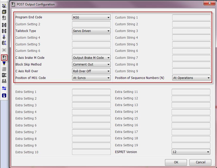
19 For NLX configuration: 14
, Program End and Rewind (M30) or Sub-Program End (M99) On the POST Output Configuration, set Program End Code to M02 to output M02, set it to M30 to output M30 or set it")
20 Output of Program End (M02), Program End and Rewind (M30) or Sub-Program End (M99) On the POST Output Configuration, set Program End Code to M02 to output M02, set it to M30 to output M30 or set it to M99 to output M99 at the end of the NC code of each turret. Please note that M30 is the default Work unloader on spindle 1 or spindle 2 side (for NLX configuration only) On the POST Output Configuration, set Work Unloader Spindle Side to On Spindle 2 Side if the work unloader of your machine is installed on the spindle 2 side; set it to On Spindle 1 Side if it is installed on the spindle 1 side. This will affect the NC output when you program your finished part catching. It will differ based on the location of work unloader present on your machine. 15
21 Please note that machine with work unloader installed on spindle 1 side is the default. For additional information on how to program finished part catching, see part Finished part catching Type of tailstock installed on the machine On the POST Output Configuration, set Tailstock Type to Carriage Direct-Coupled if your machine is equipped with a carriage direct-coupled tailstock; set it to Servo Driven (Digital for NLX configuration) if it is equipped with a servo driven (digital for NLX configuration) tailstock. This will affect the NC output when you program your tailstock operations. It will differ based on the type of tailstock present on your machine. In addition for NZX configuration, based on the type of tailstock and machine, you will have to program your tailstock on head 1 or on head 2: NZX2500 NZX4000 NZX6000 Servo driven tailstock HEAD1 - HEAD1 Carriage direct-coupled tailstock HEAD1 HEAD2 HEAD2 Please note that machine with servo driven (digital for NLX configuration) tailstock is the default. For additional information on how to program tailstock, see part Tailstock Tool station for part transfer and work unloader (for NLX configuration only) By default, station 1 will be used as empty station during part transfer and work unloader. It can be changed on the POST Output Configuration using the textbox Station on Turret 1 for Transfer. You can enter a value between 1 and 10 (for turret with 10 tool stations), between 1 and 12 (for turret with 12 tool stations; option on machine) or between 1 and 20 (for turret with 20 tool stations; option on machine). For example, if Station on Turret 1 for Transfer is set to 4, the tool call for transfer will be T0400. Note: If the station number specified is out of range (value entered greater than 10 (for a turret with 10 tool stations for example) or less than 0), you will get the following error message in your NC code: ERROR: WRONG TRANSFER STATION NUMBER ENTERED IN MACHINE SETUP. 16
22 For additional information on finished part catching and part transfer, see part 11. How to program finished part catching and part transfer C-axis brake clamp/unclamp By default, C-axis brake clamp (M68 for spindle 1 and M268 for spindle 2) and unclamp (M69 for spindle 1 and M269 for spindle 2) M-codes will be output in the NC code. If you do not want to output these M-codes in the NC code, set on the POST Output Configuration C-Axis Brake M Code to Do Not Output M Code Set how to skip turning spindle control (for NZX configuration only) When using spindle priority on turning cycles (see part 8.2. Other turning cycles), you can specify using Block Skip Method on the POST Output Configuration how to skip the turning spindle control (spindle start and spindle stop) on the slave turret. By default, the turning spindle control on the slave turret will be commented out. Set on the POST Output Configuration Block Skip Method to Block Skip to skip turning spindle control with block skip (/). Set on the POST Output Configuration Block Skip Method to Block Skip 2 to skip turning spindle control with block skip 2 (/2) C-axis roll over On the POST Output Configuration, set C-Axis Roll Over to Roll Over On to turn on C- axis roll over. Note that you will need to turn it on on the machine control as well. On machine control, if <Roll over for C-axis> is invalid (NC Parameter 1008 bit 0 = 0): min. C-axis value is max. C-axis value is In ESPRIT, C-Axis Roll Over on the POST Output Configuration is set to Roll Over Off. On machine control if <Roll over for C-axis> is valid (NC Parameter 1008 bit 0 = 1): min. C-axis value is max. C-axis value is In ESPRIT, C-Axis Roll Over on the POST Output Configuration is set to Roll Over On. When C-axis roll over is on, C-axis will be indexed between -360 and
23 Note: During 4-axis milling (wrap and rotary face milling) operations with C-axis roll over on, if C-axis value exceeds a revolution (value output greater than 360 or less than ), you will get the following error message in your NC code: ERROR: C-AXIS OVER LIMIT: ROLL-OVER MUST BE TURNED OFF Set position of optional stop code (M01) in the NC code By default, optional stop codes (M01) will be output on each head after synchronization codes in the NC code for NZX configuration (this way, optional stop can be turned on on the machine while running the NC code on both heads at the same time (production mode)) and will be output after each operation in the NC code for NLX configuration. Set on the POST Output Configuration Position of M01 Code to At Operations (and Syncs for NZX configuration) to output optional stop codes after each operation (and each programmed wait code for NZX configuration). If optional stop is turned on on NZX machine, this mode can only be used when running NC code on one head at a time (NC code proofing mode). Set on the POST Output Configuration Position of M01 Code to At Tool Cancels (and Syncs for NZX configuration) to output optional stop codes at tool cancellation (and after each programmed wait code for NZX configuration). If optional stop is turned on on NZX machine, this mode can only be used when running NC code on one head at a time (NC code proofing mode) Set position of sequence numbers (N) By default, sequence numbers (N) will be output at the beginning of each operation in the NC code. Set on the POST Output Configuration Position of Sequence Numbers (N) to At Tool Changes to output sequence numbers at tool change only. This setting will only affect regular cutting operations: sequence numbers for transfer operations will always be output. Sequence numbers for SolidTurn Roughing operations with canned cycle on will also always be output. This is to avoid sequence number mismatch since sequence numbers will be used at the beginning and at the end of profile description. 18
24 5. Tools (T function) 5.1. T function specifications T[][][][]; Introduction The first two digits of a T number specify the tool number and the tool geometry offset number. The last two digits of a T number specify the tool wear offset number. NZX : NLX : For turret with 10 tool stations: Spindle to use T Code to specify 1 Spindle 1 T T Spindle 2 T T1040 For turret with 12 tool stations (option on machine): 19
25 Spindle to use T Code to specify 1 Spindle 1 T T Spindle 2 T T1242 For turret with 20 tool stations (option on machine): Spindle to use T Code to specify 1 Spindle 1 T0101 T Spindle 2 T0131 T2050 Note: It is recommended to use the same number for the tool number and tool wear offset number when specifying a T command in a program to avoid operator's errors. In ESPRIT, you have two different ways to enter the tool call number that will be output in the NC code. They will be explained below Specify the tool number: Method 1 A tool number in ESPRIT shall be entered as three- (101, for example) or four-digit numbers (1414, for example). It will be entered in the Tool Number dialogue box on the respective tool page. It will then be output in the NC code. If, for example on turret 1, the Tool Number entered is 101, the tool call output will be T0101. If 1414 is entered, the tool call output will be T1414. Turning tools: 20
26 Milling tools: 21
27 Specify the tool number: Method 2 If the Tool Number is entered as a one-digit number (1, for example) or a two-digit number (14 for example) in ESPRIT, the post processor will combine this number to the number entered in the Length Register dialogue box. If, for example on turret 1, the Tool Number entered is 1 and the Length Register number entered is 3, the tool call output will be T0103. Turning tools: 22

28 Milling tools: 23
29 Additional information: Tool call when machining on spindle 2 side When machining on spindle 1, the tool number will be output directly as entered in the Tool Number dialogue box if method 1 is used or as a combination of the entered Tool Number and Length Register number if method 2 is used. When machining on spindle 2, the post processor will add 30 to the tool number entered in the Tool Number dialogue box if method 1 is used or to Length Register number if method 2 is used. See the examples below: Example 1 for method 1: If 101 is entered in the Tool Number dialogue box, T0131 will be output in the NC code. Example 2 for method 1: If 1212 is entered in the Tool Number dialogue box, T1242 will be output in the NC code. 24
30 Example 1 for method 2: If Tool Number it set to 1 and Length Register number is set to 3, T0133 will be output in the NC code. Example 2 for method 2: If Tool Number it set to 10 and Length Register number is set to 10, T1040 will be output in the NC code Restrictions Tool number and tool geometry offset T[][] range of values for NZX configuration: The two first digits of a tool call entered in ESPRIT have to be contained between 1 and 12 for turret 1 and between 1 and 10 for turret 2. Tool number and tool geometry offset T[][] range of values for NLX configuration: The two first digits of a tool call entered in ESPRIT have to be contained between 1 and 10 (for turret with 10 tool stations), between 1 and 12 (for turret with 12 tool stations; option on machine) or between 1 and 20 (for turret with 20 tool stations; option on machine). Note: If the Tool Number is out of range, you will get the following error message in your NC code: ERROR: WRONG TOOL NUMBER ENTERED IN ESPRIT. Tool wear offset T [][] range of values for NZX configuration: Head 1: The entered Length Register number has to be contained between 1 and 40. Head 2: The entered Length Register number has to be contained between 1 and 40. Tool wear offset T [][] range of values for NLX configuration: Machining on spindle 1 side: The entered Length Register number has to be contained between 1 and 80. Machining on spindle 2 side: The entered Length Register number has to be contained between 1 and 50, 30 will be added to this number. Note: If the entered Length Register number is out of range, you will get the following error message in your NC code: ERROR: WRONG LENGTH REGISTER NUMBER ENTERED IN ESPRIT Tool life management There are two types of tool life management for these machines: one is counting by length of time, the other is counting by times used. Counting by length of time: 25
31 On the Custom tab of the tool page, set Tool Life Management (Custom Setting 8) to 99 to turn on this type of tool life management. This will trigger the output of T****99. Turning tool page: Milling tool page: 26
32 Counting by times used: On the Custom tab of the tool page, set Tool Life Management (Custom Setting 8) to 99 and Count by Times Used (Custom Setting 9) to 89 to turn on this type of tool life management. Turning tool page: 27

33 Milling tool page: 28
 to 30 to use the second zero return of the machine (G30) for this tool.")
34 For both types of tool life management, if you omit (or enter a wrong value) to enter the value in the Tool Life Management field, the tools will be called with G00; T****99 (and M89) will not be output in the NC code Second home position On the Custom tab of the tool page, set G30 or G28 (Custom Setting 3) to 30 to use the second zero return of the machine (G30) for this tool. Turning tool page: 29
35 Milling tool page: 30
36 This will trigger the output of G30 (instead of G28) whenever a turret needs to be sent home. If you omit (or enter a wrong value) to enter the value in the G30 or G28 field, turrets will be sent to the machine zero point with G28; G30 will not be output in the NC code Set tool movements Set tool movements from tool change position In ESPRIT, on the Assembly tab of the Machine Setup, select a turret from the list on the left hand side of the window. You will then see the pull-down Moves From Tool Change. It will let you specify how the tool moves away from its position to the start of the next operation once indexed during a tool change. 31
37 Moves From Tool Change can be set to: XY Next Z: The tool moves along X and Y only to the entry location, then moves into position along the Z-axis. XYZ: Linear interpolation is used to move the tool from the tool change position to the start of the cut in a straight line. XZ Next Y: The tool moves along X and Z only, then moves along the Y-axis. YZ Next X: The tool moves along Y and Z only, then moves along the X-axis. Notes: Based on your selection, the movements output in the NC code will change accordingly. When loading a Machine Setup of the Mori Seiki NZX or NLX series, the default selection for Moves From Tool Change is YZ Next X Set tool movements to tool change position In ESPRIT, on the Assembly tab of the Machine Setup, select a turret from the list on the left hand side of the window. You will then see the pull-down Moves To Tool Change. It will let you specify how the tool moves away from the end of the previous operation to the tool change position of the next tool. 32

38 Moves To Tool Change can be set to: X First: The tool moves away from the part along the X-axis first, then moves along Y and Z to the tool change position of the next tool. XYZ: Linear interpolation is used to move the tool in a straight line from the part to the tool change position of the next tool. Y First: The tool moves along the Y-axis first, then along X and Z. Z First: The tool moves along the Z-axis first, then along X and Y. Notes: Based on your selection, the movements output in the NC code will change accordingly. The selection of Moves To Tool Change movement will override the selection made for Moves From Tool Change. For example, if both Moves To & From Tool Change are set to XYZ and Moves To Tool Change is changed to X First, Moves From Tool Change will automatically be changed to YZ Next X. This is to maintain consistency in the tool movements before and after an operation. When loading a Machine Setup of the Mori Seiki NZX or NLX series, the default selection for Moves To Tool Change is X First Moves to tool change position optimization 33

39 Using the Tool Change Movement X, Y, Z settings on the turning and milling tool pages, you can optimize your tool movements to its tool cancel position. These settings will allow you to fully utilize the production capabilities of your machine. Note that the tool cancel position of the current tool is also the tool change position of the next tool that will be used. Turning tools: Milling tools: 34

40 Movement X, Y, Z can be set to: None: The tool will not move along the selected axis. If you set for example Movement X to None, the tool will not move along the X-axis when going to the tool cancel position. Home: The tool will be sent to the machine zero point with G28 along the selected axis. Note that second home position G30 can be output instead of G28, please see part Second home position for additional information. This is the default when creating a new tool. Machine: The tool will move along the selected axis in the machine work coordinate (G53) to the specified position in Position X, Y, Z fields. Position: It cannot be used. 35
41 Note: The X; Y & Z positions entered in ESPRIT (for Machine mode) are absolute in YZX. So the post processor will compute and output the correct values from this absolute position based on the turret and the spindle in use. Once the tool movement has been optimized, the movements sequence will be given by the Moves To Tool Change setting in the ESPRIT Machine Setup (see part Set tool movements to tool change position). See the examples below: Example 1: If Moves To Tool Change is set to X First and Movement X, Y, Z is set to Machine (Position -100), Home, Home, the NC code output at tool cancel will be: G53 X G28 V0 W0 Example 2: If Moves To Tool Change is set to XYZ and Movement X, Y, Z is set to Home, Home, Home, the NC code output at tool cancel will be: G28 U0 V0 W0 Example 3: If Moves To Tool Change is set to Z First and Movement X, Y, Z is set to None, Machine (Position 10), Home, the NC code output at tool cancel will be: G28 W0 G53 Y10.0 Note that if your Moves To Tool Change and Movements X, Y, Z combination would result in impossible movement (movement that would trigger an alarm on the machine for example), you will get an error message at the beginning of your NC code. Here is a list of impossible movements: Trying to output G28 & G53 on the same line in the NC code: Home & Machine cannot be used on combined axes movements. Position cannot be used: if any axis is set to position, an error message will be output for that tool. None cannot be set for all three axes at the same time: the tool needs to be moved away at the end of an operation before indexing of the next tool for safety reasons. The output error message will list all the incorrectly set tools to help you find what tools need to be modified. Here is an example of an impossible movement that will trigger the output of an error message: If Moves To Tool Change is set to XYZ and Movement X, Y, Z is set to Home, Machine, None, you will get this error message in the NC code: ERROR: TOOL CHANGE MOVEMENT NOT DEFINED CORRECTLY FOR TOOL: TURNING INSERT OD UL; OPERATION: CONTOURING FACE. Notes: 36
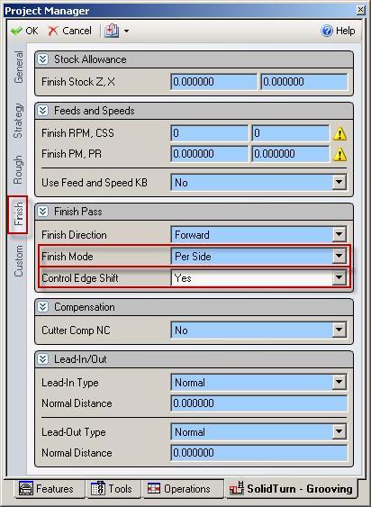
42 The very first tool of a program will always be called from home (G28). Tool cancel position of current tool will match tool change position of the next tool. Movements X, Y, Z set to None, None, None can only be used for dummy tools created for park cycle. If your machine configuration does not have a Y-axis, Movement Y will not have any effect on the error checking routine when defining your optimized tool change position. By default, tools will be sent home at tool change and at tool cancel with X-axis moved first SolidTurn Grooving: Control Edge Shift When you finish a groove with control edge shift, you can output the NC code controlling the left corner of the grooving insert for the left side of the groove and its right corner for the right side of the groove. You can assign to your grooving insert two different tool wear offset data. One register will be for the left edge of the tool and another will be for the right edge. To enable Control Edge Shift in ESPRIT, on the Finish tab of the SolidTurn Grooving operation, set Control Edge Shift to Yes. 37
43 38

44 Notes: This is only effective for the finish pass of the groove. The Finish Mode has to be set to Per Side. The second tool wear offset data can be specified on the General tab of the Grooving Insert tool page in the Edge Shift Register field: 39
45 Tool wear offset range of values for NZX configuration: Head 1: The entered Edge Shift Register number has to be contained between 1 and 40. Head 2: The entered Edge Shift Register number has to be contained between 1 and 40. Machining with tool life management on: The entered Edge Shift Register number has to be contained between 1 and 40. Tool wear offset range of values for NLX configuration: Machining on spindle 1 side: The entered Edge Shift Register number has to be contained between 1 and 80. Machining on spindle 2 side: The entered Edge Shift Register number has to be contained between 1 and 50, 30 will be added to this number. Machining with tool life management on: The entered Edge Shift Register number has to be contained between 1 and
46 Note: If the entered Edge Shift Register number is out of range, you will get the following error message in your NC code: ERROR: WRONG EDGE SHIFT REGISTER NUMBER ENTERED IN ESPRIT Automatic Determination of Tool Nose Radius (G46) Instead of using G41 or G42 to determine left or right tool offset values, users may choose to use G46 and have their machine automatically determine the correct offset side for the tool using G46. To use G46 for any operation in ESPRIT, the user needs to set Tool Nose Detect (Custom Setting 10) on the operations page to 46. When Cutter Comp NC is set to Yes, the post will automatically output G46 in place of either G41 or G42. Operations page, Strategy tab: 41

47 Operations page, Custom tab: 42
, the spindle direction")
48 6. Spindle direction, speed (S function) and feedrate (F function) 6.1. Turning spindle direction and milling tool spindle direction For turning operations using a cutting insert (Roughing, Balanced Roughing, Contouring, Grooving and Threading), the spindle direction will automatically be computed by the post processors and will output the correct M-code (M03, M04, M203 or M204) based on the hand of the tool on the holder and the orientation of the tool. The field Spindle Direction on the General tab has not effect on the output. 43

 The turning")

49 For the turning Drilling and milling operations, the turning spindle direction or milling tool spindle direction is specified by the Spindle Direction pull-down on the first tab of the tool page Turning spindle gear M-codes (for NZX configuration only) The turning spindle on NZX6000 machines (B, C and D types) is equipped with gears, as is the spindle on all NZX4000 machines: M40 (neutral gear, can be used to rotate the 44

50 spindle by hand), M41 (low speed gear) and M42 (high speed gear) have to be output in NC code in upper turret for turning operations. In ESPRIT, the gear M-code can be selected using the Spindle Range pull-down on the General tab of each turning operation page. NZX6000 (B and C types) and all NZX4000: Set Spindle Range to: Off to output M40 Low to output M41 High (Medium or Range 4) to output M42 45

51 NZX6000 (D type): Set Spindle Range to: Off to output M40 Low (Medium, High or Range 4) to output M41 Note that NZX6000 (E type) and all NZX2500 do not have gears: the above described M- codes are not necessary and so will not be output in NC code Spindle speed output for CSS unit 46
52 On a turning operation page, if you choose to output the turning spindle speed in the unit CSS (Constant Surface Speed), a warm up speed will first be output with the G97 code before the first positioning move. The speed value is computed at the first diameter from where the CSS command will be turned on. Next, after positioning the tool, the CSS is turned on by the output of G96 S. The cut is done and finally, at the last diameter, the CSS is cancelled by the output of G97 S with S computed at the current last diameter Feedrate for 4-axis milling operations For Wrap Pocketing and Wrap Contouring operations with Cylindrical Interpolation set to No, Rotary Face Pocketing and Rotary Face Contouring operations with Polar Interpolation set to No or 5-axis operations with 5 th axis locked with Z-axis (5-axis operation becomes a 4-axis operation), a rotary feedrate will be computed by the post processor, based on the linear and rotary (C-axis) moves of the cut. This computation is necessary since two types of feedrate are involved for 4-axis wrap cuts: linear feedrates (linear moves along XYZ) in mm/min (or inch/min) and rotary feedrates (angular moves around the C-axis) in deg/min. In ESPRIT, when programming such operations, simply enter the desired XY and Z PM (per minute) feedrate values. The post will then, based on these values, compute the correct 4-axis feedrate. 47
, enter the desired rapid feedrate value in the Rapid Feedrate (G01 F) (Custom Setting 1) field of the Custom tab")
53 6.5. Output of rapid positioning moves (G00) with linear interpolation moves (G01 F) CAUTION!!! Works with milling operations By default, rapid positioning moves will be output with G00 in the NC code. If you want to output your rapid positioning moves with linear interpolation (G01 F), enter the desired rapid feedrate value in the Rapid Feedrate (G01 F) (Custom Setting 1) field of the Custom tab of the milling operation page. 48

54 7. How to output coolant codes 7.1. Introduction The Mori Seiki NZX & NLX Series can handle multiple different types of coolant: Code M08 M09 M382 M383 M478 M479 Function Coolant ON Coolant OFF Bed cover chip removal coolant system ON Bed cover chip removal coolant system OFF Through-spindle coolant ON Through-spindle coolant OFF The post processor will handle the output of two different coolant codes per tool Set the first coolant code The first coolant code can be selected using the Coolant pull-down menu on the tool pages. Turning tool page: 49

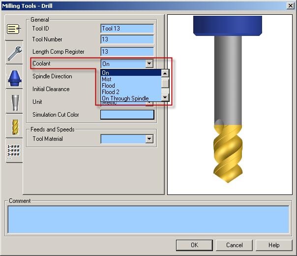
55 Milling tool page: 50
56 Set Coolant to: On to output M08 (M09) Flood to output M382 (M383) Flood Through Spindle to output M478 (M479) 7.3. Set the second coolant code (optional) If you desire to output a second coolant code (which is optional), enter the coolant code value in the Second Coolant (Custom Setting 1) field of the Custom tab of the tool page. Turning tool page: Milling tool page: 51
57 Set Second Coolant to: 8 to output M08 (M09) 382 to output M382 (M383) 478 to output M478 (M479) 7.4. Set a special coolant code (optional) If you desire to output a special coolant code (which is optional, like high pressure coolant code for example), enter the coolant code ON value in the Special Coolant ON (Custom Setting 6) field of the Custom tab of the tool page and the coolant code OFF value in the Special Coolant OFF (Custom Setting 7) field of the Custom tab of the tool page. Note that both values will need to be entered for the M-codes to be output in the NC code. The codes will then be output in NC code: special coolant code ON will be output before turning spindle or live tool speed output; special coolant code OFF will be output after turning spindle or live tool stop code (M05). 52
 8.1.")

58 8. Simultaneous turning operations: Turning on the same spindle with 2 different turrets (for NZX configuration only) 8.1. Balanced roughing cycle When programming a Balanced Roughing cycle, you have the choice between two different balanced modes: Trailing Tool: there is a user defined trailing distance between the two inserts. Simultaneous: the cut is mirrored between the turrets, the feedrates can be doubled. 53
59 For the Trailing Tool balanced mode, a wait code (soft sync) will be output in between each pass. For the Simultaneous balanced mode, the Balanced Cut Mode (G68) will be turned on on both involved heads and will be canceled at the end of the cut by the Balanced Cut Mode Cancel code (G69). The spindle speed will only be output in channel 1, not in channel Other turning cycles When two heads are cutting at the same time on the same spindle, the spindle command of a head can override the spindle command of the other head. For not having this problem, the head with the longest operation must have the control of the spindle speed. The head controlling the spindle and the head slave are set on the operation page of turning operations, using the Spindle Priority setting: 54
 or block skip 2 (/2), see part 4.4.7. Set how to skip turning spindle control). Note: Make sure, if needed, to activate the block delete function on the control.")
60 Set Spindle Priority to: Off or On to output the spindle speed Other Operation: the other head is controlling the spindle and the spindle speeds are output (by default) as comments (or with a block skip (/) or block skip 2 (/2), see part Set how to skip turning spindle control). Note: Make sure, if needed, to activate the block delete function on the control. 55
, you will need to synchronize head 1 & head 2 prior to the turning operations with the SimMach Sync Code.")

61 8.3. Other turning cycles in Balanced Cut Mode CAUTION!!! Do not use with SolidTurn Drilling. To program simultaneous turning operations in Balanced Cut Mode (G68), you will need to synchronize head 1 & head 2 prior to the turning operations with the SimMach Sync Code. It will trigger the simultaneous turning in Balanced Cut Mode: G68 will be output to turn on Balanced Cut Mode at the beginning of the operations and G69 will be output to turn it off at the end of the operations. This functionality is typically used to perform pinch grooving operations. To program the SimMach Sync Code, you can in ESPRIT create a Sync and then double click on it on the Operations tab of the Project Manager and change the Sync Code to SimMach. After clicking on OK, your Sync will become a SimMach Sync Code. 56

62 Or, you can also directly select SimMach from the pull-down on top of the Operations tab of the Project Manager. Once selected, simply program your sync: it will be a SimMach Sync Code. 57


63 Note: The SimMach Sync Code will not output an actual wait code. Its only functionality is to trigger simultaneous turning in Balanced Cut Mode. This mode will be turned off at the next programmed wait code. So if you program multiple synchronized turning operations in a row, make sure to follow this routine to avoid possible machine crash: SimMach Sync Code followed by Turning operation followed by Regular wait code... 58
64 Note that since two heads are cutting at the same time on the same spindle, the head with the longest operation must have the control of the spindle speed. For additional information on how to set the spindle priority, see part 8.2. Other turning cycles. Notes: If you have an operation type mismatch (milling on head 1 while turning on head 2) below the SimMach Sync Code, you will get the following error message in your NC code: ERROR: OPERATIONS TYPE DIFFERS BETWEEN HEAD 1 AND HEAD Operation synchronization (for NZX configuration only) Operation synchronization M-codes start at M101 and can incrementally reach M197. In the NC code, when M197 is reached or exceeded, the next output wait code will be output in the (101; 197) range: M197 will never be exceeded. 10. Park cycle Introduction With the Park cycle of ESPRIT, you will have different possibilities to park a tool located on head 1 (or 2 for NZX configuration). It is a great way to park a tool above a spindle to a clearance position, so you can for example freely machine on the same spindle with another turret for NZX configuration. You can also send a tool home along the X, Y (Yaxis specifications only) and/or Z axis. You finally can park the turret to its maximal positions (left or right) or anywhere in-between using the machine work coordinate system (G53) How to park a tool On the Park tab of the Park operation page, using the Park Position X, Y & pull-downs and fields, you can set how and where you want to park your tool. 59

65 Set Park Position X, Y or Z to: None: The tool will not move along the selected axis. If you set for example Park Position X to None, the tool will not move along the X-axis when going to the park position. Home: The tool will be sent to the machine zero point with G28 along the selected axis. Note that second home position G30 can be output instead of G28, please see part Second home position for additional information. This is the default when creating a new tool. Machine: The tool will move along the selected axis in the machine work coordinate (G53) to the specified position in Position X, Y, Z fields. Position: The tool will be parked at the specified position in Position X, Y, Z fields at rapid traverse rate (G00). 60


66 Note: The X; Y & Z positions entered in ESPRIT (for Machine and Position modes) are absolute in YZX. So the post processor will compute and output the correct values from this absolute position based on the turret and the spindle in use. Once your tool movements correctly defined, you will be able to set the Return Mode. It controls how the axes move to the park position. This setting is available only when at least 2 axes are allowed to move during the park. The different existing Return Modes are: None: All axes move directly to the park position. All axes allowed to move will move together. X First: The X axis is moved first to Park Position X. Then all other axes move in a second step. Y First: The Y axis moves first. Then all other axes move together. Z First: The Z axis moves first. Then all other axes move together. X Then Y: X moves first, then Y, then Z. X Then Z: X moves first, then Z, then Y. Y Then X: Y moves first, then X, then Z. 61
67 Y Then Z: Y moves first, then Z, then X. Z Then X: Z moves first, then X, then Y. Z Then Y: Z moves first, then Y, then X. The options available for Return Mode depend on the axes selected for movement and their positions type (None, Home, Machine or Position). See the examples below: Example 1: If Park Position X is set to Home, Park Position Y set to None and Park Position Z set to Home: the choices for Return Mode become None, X First or Z First. Example 2: If Park Position X is set to Home, Park Position Y set to Home and Park Position Z set to Machine: the choices for Return Mode become Z First, X Then Y, X Then Z, Y Then X, Y Then Z, Z Then X or Z Then Y. Since movements in machine work coordinate system (G53) cannot be output in the NC code on the same line as movements home (G28), ESPRIT is filtering the forbidden combinations. These combinations will always have Z movement output on its own line in the NC code. Example 3: If Park Position X, Y & Z are all set to Home: all Return Modes become available. Note that If your machine does not have a Y-axis, any Y-axis movement programmed with the Park cycle will be ignored Park a turret to its maximal travel position (G53) You will need to set Position with G53 (Custom Setting 1) of the Park operation to 53 or -53 to enable the output of the G53 code. If you set Position with G53 to -53, the active turret will be parked to its left maximal travel position. 62
 for NZX configuration: NZX 6000 4000 2500 1000 2000 3000 1000 1500 2000 3000 600 1000 Left position Right position Upper")
68 Set Position with G53 to 53 to park it to its right maximal travel position. Turrets maximum travel position values (in the machine coordinate system G53) for NZX configuration: NZX Left position Right position Upper turret T1 G53 Z G53 Z230.0 Lower turret T2 G53 Z G53 Z90.0 Upper turret T1 G53 Z G53 Z80.0 Lower turret T2 G53 Z G53 Z80.0 Upper turret T1 Lower turret T2 Upper turret T1 G53 Z G53 Z80.0 Lower turret T2 G53 Z G53 Z80.0 Upper turret T1 Lower turret T2 Upper turret T1 G53 Z G53 Z80.0 Lower turret T2 G53 Z G53 Z80.0 Upper turret T1 Lower turret T2 Upper turret T1 G53 Z G53 Z50.0 Lower turret T2 G53 Z G53 Z50.0 Upper turret T1 G53 Z G53 Z50.0 Lower turret T2 G53 Z G53 Z50.0 Turret maximum travel position values (in the machine coordinate system G53) for NLX configuration: Left position: -745 mm Right position: 50 mm 63
69 Note that if the tool you are parking is the same as the previous tool in use, the turret will be sent home in Y (Y-axis specifications only) then X before the G53 output as a safety Park a turret prior to a transfer (for NLX configuration only) By default, tool station 1 will be called prior to a transfer. As seen in part Tool station for part transfer and work unloader, this tool station can be changed using the Station on Turret 1 for Transfer textbox on the POST Output Configuration. Once correctly setup, you can park the turret using the Park cycle (with G53) prior to a transfer. You will first need to create a dummy tool on the turret, in the right station. Set the Tool Number to 1 (or whatever you set up in the Machine Setup) and the Length Comp Register to 0, or simply set the Tool Number to 100 (or whatever you set up in the Machine Setup time 100) and the Length Comp Register to the same number. 64

70 Then, simply program a Park operation using this previously defined tool prior to the transfer sequence. Note that since the tool call will be made without tool wear offset number, you will need to set Position with G53 to 53 (or -53, see part Park a turret to its maximal travel position (G53)) on the Park operation Custom tab. The turret will be parked using G53. Note: If you omit to enter 53 in the Position with G53 field of the Park operation, you will get the following error message in your NC code: ERROR: NO TOOL WEAR OFFSET: PARK WITH POSITION (USING G00) CANNOT BE USED Other functionalities If you set Output M09 (Custom Setting 2) to 1 on the Custom tab of the Park operation, the coolants will be stopped. On the Park tab of the operation, if you set Stop Code to Optional Stop or Stop, a Spindle Rotation Stop Code (M05) will be output. 65
 in ESPRIT. A correct program in ESPRIT is necessary to have a correct NC code.")
71 11. How to program finished part catching and part transfer Introduction In this following part, you will be given detailed instructions on how to manually program various catching of finished part and various part transfers (for NLX configuration only) in ESPRIT. A correct program in ESPRIT is necessary to have a correct NC code. Please note that the following part catching and part transfer scenarios can be programmed automatically using the Workpiece Transfer add-in for NLX configuration Finished part catching Catching finished part on spindle 1 side after cut-off (for NLX configuration only) It can be performed if your machine is equipped with a receiver installed on the spindle 1 side. Note: On the General tab of the Machine Setup, set the Start Position Z: Start Position Z = Length of stock for facing the front side of the part 66
72 The regular steps to follow are: 1. Machining the part on the spindle 1 side 2. Perform a cut-off operation Steps to program this part ejection type in ESPRIT: 1. Machining the part on the spindle 1 side. 2. Cut-off: Use operation Cutoff using tool on MainSpindle (Spindle Name). To trigger the part catching output, set Use Part Catcher to Yes on the Strategy tab. 67

73 Sample operation list: 68

74 Catching finished part on spindle 1 side after cut-off with stock repositioning (programmed first) (for NLX configuration only) If your machine is equipped with a barfeeder, you can reposition the stock, machine the part, catch the finished part on spindle 1 side and finally loop for the next part. Note: On the General tab of the Machine Setup, set the Start Position Z: Start Position Z = - (Length of the finished part (Part Stock Length) + Cut-off tool width + Length of stock for facing the back side of the part (if needed)) The steps to follow are the same as previous point. The only difference is that you need to program a barfeed (by stopper) operation first: 1. Perform a barfeed operation 2. Machining the part on the spindle 1 side 3. Perform a cut-off operation 4. Looping for next parts Steps to program this part ejection type in ESPRIT: 1. Perform a barfeed operation: Use operation Bar Feed By Stopper (Bar Feed Type) using tool on MainSpindle (Spindle Name). On Bar Feed tab, set the Feed Length and Reposition Distance: Feed Length (=Barfeed distance) = Length of the finished part (Part Stock Length) + Cut-off tool width + Length of stock for facing the front side and, if needed, the back side of the part Reposition Distance = 0 With Position X, Y, Z, set the barfeed reference point. Its Z coordinate value should be equal to the length of stock for facing the front side of the part (if needed). 69
75 The stopper tool will either be positioned in the G53 work coordinate or the current machine work coordinate. To use G53 work coordinate: On the Custom tab, enter in the Stopper G53 X (Custom Setting 4) field the X position (in G53 work coordinate) of the stopper tool and in Stopper G53 Z (Custom Setting 5) field the Z position (in G53 work coordinate) of the stopper tool. To use current machine work coordinate defined in ESPRIT (see part 2.3. Turning Work Coordinates): If no value is specified on the Custom tab in the Stopper G53 X and Stopper G53 Z fields (fields left equal to 0), the stopper tool will be positioned at the programmed position (Position X, Y, Z specified on Bar Feed tab) in the current active machine work coordinate. 2. Machining the part on the spindle 1 side. 70

76 3. Cut-off: Use operation Cutoff using tool on MainSpindle (Spindle Name). To trigger the part catching output, set Use Part Catcher to Yes on the Strategy tab. Sample operation list: 71
77 Catching finished part on spindle 1 side after cut-off with stock repositioning (programmed last) (for NLX configuration only) If your machine is equipped with a barfeeder, you can after catching the finished part on spindle 1 side reposition the stock. This way, you can loop for the next part. Note: On the General tab of the Machine Setup, set the Start Position Z: Start Position Z = Length of stock for facing the front side of the part The steps to follow are the same as previous point. The only difference is that you need to program a barfeed (by stopper) operation last: 1. Machining the part on the spindle 1 side 2. Perform a cut-off operation 3. Perform a barfeed operation 4. Looping for next parts Steps to program this part ejection type in ESPRIT: 1. Machining the part on the spindle 1 side. 2. Cut-off: Use operation Cutoff using tool on MainSpindle (Spindle Name). To trigger the part catching output, set Use Part Catcher to Yes on the Strategy tab. 72
78 3. Perform a barfeed operation: Use operation Bar Feed By Stopper (Bar Feed Type) using tool on MainSpindle (Spindle Name). On Bar Feed tab, set the Feed Length and Reposition Distance: Feed Length (=Barfeed distance) = Length of the finished part (Part Stock Length) + Cut-off tool width + Length of stock for facing the front side and, if needed, the back side of the part Reposition Distance = 0 With Position X, Y, Z, set the barfeed reference point. Its Z coordinate value should be equal to the length of stock for facing the front side of the next part (if needed). 73
 field the X position (in G53 work coordinate) of the stopper tool and in Stopper G53 Z (Custom Setting 5)")
79 The stopper tool will either be positioned in the G53 work coordinate or the current machine work coordinate. To use G53 work coordinate: On the Custom tab, enter in the Stopper G53 X (Custom Setting 4) field the X position (in G53 work coordinate) of the stopper tool and in Stopper G53 Z (Custom Setting 5) field the Z position (in G53 work coordinate) of the stopper tool. To use current machine work coordinate defined in ESPRIT (see part 2.3. Turning Work Coordinates): If no value is specified on the Custom tab in the Stopper G53 X and Stopper G53 Z fields (fields left equal to 0), the stopper tool will be positioned at the programmed position (Position X, Y, Z specified on Bar Feed tab) in the current active machine work coordinate. Sample operation list: 74

80 Manually catching finished part on spindle 1 side This type of part release is performed when the part is completely machined on spindle 1 side. To be able to catch the finished part, the machine needs to be stopped with M00. The regular steps to follow are: 1. Machining the part on the spindle 1 side 2. Manually catching the finished part in the spindle 1 Steps to program this part ejection type in ESPRIT: 1. Machining the part on the spindle 1 side. 2. Program a wait code across the two heads for NZX configuration. 3. Manually catching the finished part in the spindle 1: To be able to manually catch the finished part in the spindle 1, the machine needs to be stopped. To do so, the M-code M00 (program stop) needs to be output (in both heads after the same sync code across the two heads (this is the reason why a sync code across the two heads needs to be programmed prior to the part release operation) for NZX configuration). Use operation Release with MainSpindle (Spindle Name) on Lower Turret (Turret Name) (for NZX configuration). To output the stop code M00, set Part Chute to No on the Release tab. 75


81 Note for NZX configuration: If you do not program a sync above your part release or do not set Part Chute to No, you will get the following error message in your NC code (in head 2): ERROR: PROGRAM A SYNC ABOVE PART EJECT OPERATION & SET PART CHUTE TO NO TO OUTPUT M00. Sample operation list for NZX configuration: Sample operation list for NLX configuration: 76
82 Catching finished part on spindle 2 side (for NLX configuration only) This type of part release is performed when the part is completely machined on spindle 2 side. The regular steps to follow are: 1. Machining the part on the spindle 2 side 2. Catching the finished part in the spindle 2 Steps to program this part ejection type in ESPRIT: 1. Machining the part on the spindle 2 side: Note: The operations on the spindle 2 side are output with the origin shifted to the other face of the part (back face). During operations, only positive Z coordinates are output. The setting Part Stock Length from the Machine Setup is used as default value for Turning Work Coordinates Sub Spindle Z Offset. CAUTION!!! Part Stock Length = Finished Part Length. You must run the Turning Work Coordinates add-in prior to posting NC Code in order to have correct NC output. 2. Catching the finished part in the spindle 2: Use operation Release with SubSpindle (Spindle Name). Based on the setting set for Work Unloader Spindle Side on the POST Output Configuration (see part Work unloader on spindle 1 or spindle 2 side), the NC output will differ to match your machine specifications: receiver installed on spindle 1 or spindle 2 side. Catching the finished part in the spindle 2 on a machine with receiver installed on spindle 1 or spindle 2 side: Once you specified on which spindle side the receiver is mounted on the machine, to trigger the part catching output, set Part Chute to Yes on the Release tab. In the Catch Position (Custom Setting 8) field of the SolidTurn Release operation page, enter the part catching position. The spindle 2 will rapid to this position. Note that you can enter a positive or negative value, the output position will always be negative since it is output in the machine work coordinate (G53). 77
 option on machine. If you omit to enter a value in the Workpiece Ejector (M47) field or enter a wrong value, no part ejection code will be output in the NC code.")
83 With Workpiece Ejector (M47) (Custom Setting 9), you can specify if you want to eject the finished part with the optional ejector: set Workpiece Ejector (M47) to 47 if you have the workpiece ejector OUT (M47) option on machine. If you omit to enter a value in the Workpiece Ejector (M47) field or enter a wrong value, no part ejection code will be output in the NC code. Manually catching the finished part in the spindle 2 (machine is stopped with M00): To be able to manually catch the finished part in the spindle 2, the machine needs to be stopped. To do so, the M-code M00 (program stop) needs to be output. To output the stop code M00, set Part Chute to No on the Release tab. Sample operation list of finished part catching with receiver or of manual part catching: 78

84 11.3. Part transfer (for NLX configuration only) Part transfer from spindle 1 to spindle 2 with cut-off Note: On the General tab of the Machine Setup, set the Start Position Z: Start Position Z = Length of stock for facing the front side of the part The regular steps to follow are: 1. Machining the part on the spindle 1 side 2. Picking the part in the spindle 1 with the spindle 2 3. Pulling the bar with the spindle 2 (if needed) 4. Perform a cut-off and then the spindle 2 goes back home 5. Machining the part on the spindle 2 side 6. Catching the finished part in the spindle 2 7. Looping for next parts 79
85 Note: It is also possible to perform all operations on spindle 1 and spindle 2 sides and then finish with the part transfer (after first catching finished part in the spindle 2). Steps to program this transfer type in ESPRIT: 1. Machining the part on the spindle 1 side. 2. Picking the part in the spindle 1 with the spindle 2: Use operation Pickup with SubSpindle (Spindle Name). With Position X, Y, Z, set the pickup point. Set Sync Spindles to Speed and Direction Only (or to Off) for speed synchronization code output (M35) or to Oriented for phase synchronization code output (M34). The spindle speed entered on the SolidTurn Pickup page will be output after synchronization of the spindles. Enter the Feedrate PM of the spindle 2 B-axis and its clearance (from the pickup point). 80
86 3. Pulling the bar with the spindle 2 (if needed): Use operation Bar Feed by Spindle (Bar Feed Type) on MainSpindle (Spindle Name) by SubSpindle (Barfeed Spindle Name). On Bar Feed tab, set the Feed Length and Reposition Distance: Feed Length (= Barpull distance = Reposition Distance) = Length of the finished part (Part Stock Length) + Cut-off tool width + Length of stock for facing the front side and the back side of the part With Position X, Y, Z, set the same point as for the pickup operation (If the point is different, chucks will unclamp and clamp before pulling the bar). 81
87 Programming a pickup before the barpull makes the spindle 2 stay at the same location after the barpull. Without pickup operation, spindle 2 goes home after the barpull. On the General tab, enter the Feedrate PM of the spindle 2 B-axis. 4. Cut-off: Use operation Cutoff using tool on MainSpindle (Spindle Name). To output a dwell (G04 U) above workpiece cut-off detection (M80), enter in the Dwell Time field on the Rough tab of the Cutoff operation the dwell time in s. 82
.")
88 The spindle 2 automatically goes home after cut-off completion. 5. Machining the part on the spindle 2 side: Note: The operations on the spindle 2 side are output with the origin shifted to the other face of the part (back face). During operations, only positive Z coordinates are output. The setting Part Stock Length from the Machine Setup is used as default value for Turning Work Coordinates Sub Spindle Z Offset. CAUTION!!! Part Stock Length = Finished Part Length. You must run the Turning Work Coordinates add-in prior to posting NC Code in order to have correct NC output. 6. Catching the finished part in the spindle 2: Spindle 2 needs to be empty before transferring the workpiece from spindle 1 to spindle 2 (see part Catching finished part on spindle 2 side for programming details). Sample operation list with transfer (with barpull) and cut-off: Sample operation list with transfer (without barpull) and cut-off: 83
 If your machine is equipped with a barfeeder, instead of pulling the part from spindle 1, you can use")
89 Part transfer from spindle 1 to spindle 2 with cut-off (when machine equipped with a barfeeder) If your machine is equipped with a barfeeder, instead of pulling the part from spindle 1, you can use the barfeeder to position the bar before pickup and cut-off. Note: On the General tab of the Machine Setup, set the Start Position Z: Start Position Z = Length of stock for facing the front side of the part The regular steps to follow are: 1. Machining the part on the spindle 1 side 2. Perform a barfeed operation 3. Picking the part in the spindle 1 with the spindle 2 4. Perform a cut-off and then the spindle 2 goes back home 5. Machining the part on the spindle 2 side 6. Catching the finished part in the spindle 2 7. Looping for next parts Note: It is also possible to perform all operations on spindle 1 and spindle 2 sides and then finish with the part transfer (after first catching finished part in the spindle 2). 84
90 Steps to program this transfer type in ESPRIT: 1. Machining the part on the spindle 1 side. 2. Perform a barfeed operation: Use operation Bar Feed By Stopper (Bar Feed Type) using tool on MainSpindle (Spindle Name). On Bar Feed tab, set the Feed Length and Reposition Distance: Feed Length (=Barfeed distance = Reposition Distance) = Length of the finished part (Part Stock Length) + Cut-off tool width + Length of stock for facing the front side and the back side of the part With Position X, Y, Z, set the barfeed reference point. Its Z coordinate value should be equal to the entered feed length. The stopper tool will either be positioned in the G53 work coordinate or the current machine work coordinate. To use G53 work coordinate: On the Custom tab, enter in the Stopper G53 X (Custom Setting 4) field the X position (in G53 work coordinate) of the stopper tool and in Stopper G53 Z (Custom Setting 5) field the Z position (in G53 work coordinate) of the stopper tool. 85
91 To use current machine work coordinate defined in ESPRIT (see part 2.3. Turning Work Coordinates): If no value is specified on the Custom tab in the Stopper G53 X and Stopper G53 Z fields (fields left equal to 0), the stopper tool will be positioned at the programmed position (Position X, Y, Z specified on Bar Feed tab) in the current active machine work coordinate. 3. Picking the part in the spindle 1 with the spindle 2: Use operation Pickup with SubSpindle (Spindle Name). With Position X, Y, Z, set the pickup point. Note that the pickup point will be shifted by the reposition distance amount entered on Bar Feed tab of Bar Feed operation. Set Sync Spindles to Speed and Direction Only (or to Off) for speed synchronization code output (M35) or to Oriented for phase synchronization code output (M34). The spindle speed entered on the SolidTurn Pickup page will be output after synchronization of the spindles. Enter the Feedrate PM of the spindle 2 B-axis and its clearance (from the pickup point). 86
92 4. Cut-off: Use operation Cutoff using tool on MainSpindle (Spindle Name). To output a dwell (G04 U) above workpiece cut-off detection (M80), enter in the Dwell Time field on the Rough tab of the Cutoff operation the dwell time in s. 87
93 The spindle 2 automatically goes home after cut-off completion. 5. Machining the part on the spindle 2 side: Note: The operations on the spindle 2 side are output with the origin shifted to the other face of the part (back face). During operations, only positive Z coordinates are output. The setting Part Stock Length from the Machine Setup is used as default value for Turning Work Coordinates Sub Spindle Z Offset. CAUTION!!! Part Stock Length = Finished Part Length. You must run the Turning Work Coordinates add-in prior to posting NC Code in order to have correct NC output. 6. Catching the finished part in the spindle 2: Spindle 2 needs to be empty before transferring the workpiece from spindle 1 to spindle 2 (see part Catching finished part on spindle 2 side for programming details). Sample operation list: 88

94 Part transfer from spindle 1 to spindle 2 with cut-off and stock repositioning (programmed last) If your machine is equipped with a barfeeder, you can after transferring the finished part from spindle 1 to spindle 2 reposition the stock. This way, you can loop for the next part. Note: On the General tab of the Machine Setup, set the Start Position Z: Start Position Z = Length of stock for facing the front side of the part The regular steps to follow are: 1. Machining the part on the spindle 1 side 2. Picking the part in the spindle 1 with the spindle 2 3. Perform a cut-off and then the spindle 2 goes back home 4. Perform a barfeed operation 5. Machining the part on the spindle 2 side 6. Catching the finished part in the spindle 2 7. Looping for next parts 89
95 Note: It is also possible to perform all operations on spindle 1 and spindle 2 sides and then finish with the part transfer (after first catching finished part in the spindle 2). Steps to program this transfer type in ESPRIT: 1. Machining the part on the spindle 1 side. 2. Picking the part in the spindle 1 with the spindle 2: Use operation Pickup with SubSpindle (Spindle Name). With Position X, Y, Z, set the pickup point. Set Sync Spindles to Speed and Direction Only (or to Off) for speed synchronization code output (M35) or to Oriented for phase synchronization code output (M34). The spindle speed entered on the SolidTurn Pickup page will be output after synchronization of the spindles. Enter the Feedrate PM of the spindle 2 B-axis and its clearance (from the pickup point). 90
96 3. Cut-off: Use operation Cutoff using tool on MainSpindle (Spindle Name). To output a dwell (G04 U) above workpiece cut-off detection (M80), enter in the Dwell Time field on the Rough tab of the Cutoff operation the dwell time in s. 91
97 The spindle 2 automatically goes home after cut-off completion. 4. Perform a barfeed operation: Use operation Bar Feed By Stopper (Bar Feed Type) using tool on MainSpindle (Spindle Name). On Bar Feed tab, set the Feed Length and Reposition Distance: Feed Length (=Barfeed distance = Reposition Distance) = Length of the finished part (Part Stock Length) + Cut-off tool width + Length of stock for facing the front side and the back side of the part With Position X, Y, Z, set the barfeed reference point. Its Z coordinate value should be equal to the length of stock for facing the front side (of the next part). 92
98 The stopper tool will either be positioned in the G53 work coordinate or the current machine work coordinate. To use G53 work coordinate: On the Custom tab, enter in the Stopper G53 X (Custom Setting 4) field the X position (in G53 work coordinate) of the stopper tool and in Stopper G53 Z (Custom Setting 5) field the Z position (in G53 work coordinate) of the stopper tool. To use current machine work coordinate defined in ESPRIT (see part 2.3. Turning Work Coordinates): If no value is specified on the Custom tab in the Stopper G53 X and Stopper G53 Z fields (fields left equal to 0), the stopper tool will be positioned at the programmed position (Position X, Y, Z specified on Bar Feed tab) in the current active machine work coordinate. 93

99 5. Machining the part on the spindle 2 side: Note: The operations on the spindle 2 side are output with the origin shifted to the other face of the part (back face). During operations, only positive Z coordinates are output. The setting Part Stock Length from the Machine Setup is used as default value for Turning Work Coordinates Sub Spindle Z Offset. CAUTION!!! Part Stock Length = Finished Part Length. You must run the Turning Work Coordinates add-in prior to posting NC Code in order to have correct NC output. 6. Catching the finished part in the spindle 2: Spindle 2 needs to be empty before transferring the workpiece from spindle 1 to spindle 2 (see part Catching finished part on spindle 2 side for programming details). Sample operation list with transfer, cut-off and barfeed (last): Part transfer from spindle 1 to spindle 2 without cutoff The stock is manually loaded in the spindle 1; the part is not pulled. The finished part in the spindle 2 has to be released. The entire part is transferred to the spindle 2 when the work on spindle 1 is finished. Note: On the General tab of the Machine Setup, set the Start Position Z and Total Bar Length: Start Position Z = Length of stock for facing the front side of the part 94
100 Total Bar Length = Length of the finished part (Part Stock Length) + Length of stock for facing the front side and the back side of the part The regular steps to follow are: 1. Machining the part on the spindle 1 side 2. Picking the part in the spindle 1 with the spindle 2 3. Releasing the part from the spindle 1 and then the spindle 2 goes back home 4. Machining the part on the spindle 2 side 5. Catching the finished part in the spindle 2 6. Stop for loading a new stock in the spindle 1 Note: It is also possible to perform all operations on spindle 1 and spindle 2 sides and then finish with the part transfer (after first catching finished part in the spindle 2). Steps to program this transfer type in ESPRIT: 1. Machining the part on the spindle 1 side. 2. Picking the part in the spindle 1 with the spindle 2: Use operation Pickup with SubSpindle (Spindle Name). With Position X, Y, Z, set the pickup point. 95
101 Enter the Feedrate PM of the spindle 2 B-axis and its clearance (from the pickup point). During this type of transfer, the turning spindles are stopped. Using Spindle Orientation (Custom Setting 6) on the Custom tab of the Pickup operation, you can specify how you want to orient your spindles. Set Spindle Orientation to 19 if you want to use spindle orientation (M19 / M219) or set Spindle Orientation to 45 if you want to use the milling C-axis mode (M45 / M245). If you use milling C- axis mode, using C Index for M45 (Custom Setting 7), you can specify the C angle value you want to index to. Make sure to enter a correct value for C. For example, if C-axis roll-over is on (see part C-Axis roll over), C has to be contained between and
102 Note that the milling C-axis mode is the default. So if you omit to enter a value in the Spindle Orientation field or enter a wrong value, the spindles will be indexed using this mode. 3. Releasing the part from the spindle 1: Use operation Release with MainSpindle (Spindle Name). With Position X, Y, Z, set the release point. 4. Machining the part on the spindle 2 side: Note: The operations on the spindle 2 side are output with the origin shifted to the other face of the part (back face). During operations, only positive Z coordinates are output. The setting Part Stock Length from the Machine Setup is used as default value for Turning Work Coordinates Sub Spindle Z Offset. CAUTION!!! Part Stock Length = Finished Part Length. You must run the Turning Work Coordinates add-in prior to posting NC Code in order to have correct NC output. 97

103 5. Catching the finished part in the spindle 2: Spindle 2 needs to be empty before transferring the workpiece from spindle 1 to spindle 2 (see part Catching finished part on spindle 2 side for programming details). Sample operation list: Part transfer from spindle 2 to spindle 1 without cutoff The stock is manually loaded in the spindle 2; the part is not pulled. The finished part has to be manually unloaded from the spindle 1. The entire part is transferred to the spindle 1 when the work on spindle 2 is finished. Note: On the General tab of the Machine Setup, set the Start Position Z: Start Position Z = Length of stock for facing the front side of the part Total Bar Length = Length of the finished part (Part Stock Length) + Length of stock for facing the front side and the back side of the part 98
104 The regular steps to follow are: 1. Machining the part on the spindle 2 side 2. Picking the part in the spindle 2 with the spindle 1 3. Releasing the part from the spindle 2 and then the spindle 2 goes back home 4. Machining the part on the spindle 1 side 5. Stop to manually unload the finished part in the spindle 1 (and to load a new stock in the spindle 2) Note: It is also possible to perform all operations on spindle 1 and spindle 2 sides and then finish with the part transfer (after first catching finished part in the spindle 1). Steps to program this transfer type in ESPRIT: 1. Machining the part on the spindle 2 side: Note: The operations on the spindle 2 side are output with the origin shifted to the other face of the part (back face). During operations, only positive Z coordinates are output. The setting Part Stock Length from the Machine Setup is used as default value for Turning Work Coordinates Sub Spindle Z Offset. CAUTION!!! Part Stock Length = Finished Part Length. You must run the Turning Work Coordinates add-in prior to posting NC Code in order to have correct NC output. 2. Picking the part in the spindle 2 with the spindle 1: Use operation Pickup with MainSpindle (Spindle Name). With Position X, Y, Z, set the pickup point: point that you would like the back of spindle 1 to reach while picking up the part (usually the zero point of the part in the spindle 2). Enter the Feedrate PM of the spindle 2 B-axis and its clearance (from the pickup point). During this type of transfer, the turning spindles are stopped. Using Spindle 99
105 Orientation (Custom Setting 6) on the Custom tab of the Pickup operation, you can specify how you want to orient your spindles. Set Spindle Orientation to 19 if you want to use spindle orientation (M19 / M219) or set Spindle Orientation to 45 if you want to use the milling C-axis mode (M45 / M245). If you use milling C- axis mode, using C Index for M45 (Custom Setting 7), you can specify the C angle value you want to index to. Make sure to enter a correct value for C. For example, if C-axis roll-over is on (see part C-Axis roll over), C has to be contained between and
106 Note that the milling C-axis mode is the default. So if you omit to enter a value in the Spindle Orientation field or enter a wrong value, the spindles will be indexed using this mode. 3. Releasing the part from the spindle 2: Use operation Release with SubSpindle (Spindle Name). With Position X, Y, Z, set the release point. 4. Machining the part on the spindle 1 side. 5. Stop to manually unload the finished part in the spindle 1 (and to load a new stock in the spindle 2): To be able to catch the finished part in the spindle 1, the machine needs to be stopped (see part Manually catching finished part on spindle 1 side for programming details). Sample operation list: 101

107 Stock repositioning If your machine is not equipped with a barfeeder, using this type of transfer, you will be able to reposition the stock in spindle 1 using the spindle 2. This type of transfer can be programmed anywhere in the program. Note: Spindle 2 needs to be empty before repositioning since spindle 2 will pick up the part in spindle 1. The regular steps to follow are: 1. Picking the part in the spindle 1 with the (empty) spindle 2 2. Pulling the bar with the spindle 2 3. Releasing the part from the spindle 2 and then the spindle 2 goes back home Steps to program this transfer type in ESPRIT: 1. Picking the part in the spindle 1 with the (empty) spindle 2: Use operation Pickup with SubSpindle (Spindle Name). With Position X, Y, Z, set the pickup point. Enter the Feedrate PM of the spindle 2 B-axis and its clearance (from the pickup point). During this type of transfer, the turning spindles are stopped. Using Spindle Orientation (Custom Setting 6) on the Custom tab of the Pickup operation, you can specify how you want to orient your spindles. Set Spindle Orientation to 19 if you want to use spindle orientation (M19 / M219) or set Spindle Orientation to
, you can specify the C angle value you want to index to. Make sure to enter a correct value for C.")
108 if you want to use the milling C-axis mode (M45 / M245). If you use milling C- axis mode, using C Index for M45 (Custom Setting 7), you can specify the C angle value you want to index to. Make sure to enter a correct value for C. For example, if C-axis roll-over is on (see part C-Axis roll over), C has to be contained between and
109 Note that the milling C-axis mode is the default. So if you omit to enter a value in the Spindle Orientation field or enter a wrong value, the spindles will be indexed using this mode. 2. Pulling the bar with the spindle 2: Use operation Bar Feed by Spindle (Bar Feed Type) on MainSpindle (Spindle Name) by SubSpindle (Barfeed Spindle Name). On Bar Feed tab, set the Feed Length and Reposition Distance: Feed Length = Barpull distance = Length of stock that spindle 2 will pull out of spindle 1 for repositioning Reposition Distance = Set it to 0 if you do not want to shift your Z values after repositioning or set it to Feed Length if you want to shift your Z values by the repositioning distance value With Position X, Y, Z, set the same point as for the pickup operation (If the point is different, chucks will unclamp and clamp before pulling the bar). 104
.")
110 Programming a pickup before the barpull makes the spindle 2 stay at the same location after the barpull. Without pickup operation, spindle 2 goes home after the barpull. On the General tab, enter the Feedrate PM of the spindle 2 B-axis. 3. Releasing the part from the spindle 2: Use operation Release with SubSpindle (Spindle Name). With Position X, Y, Z, set the release point. Sample operation list: 105
111 Machining of long parts with spindle 1 and 2 synchronized To support the stock with both spindles, you first need to pick it up (and, if needed, pull it) with the spindle 2. You can after program your operations and in the code will be output the necessary spindles synchronization and unsynchronization codes. Finally, once machining is completed, you can program one of the transfer scenarios described in the previous parts at the end of the operation list. Note: On the General tab of the Machine Setup, set the Start Position Z: Start Position Z = Length of stock for facing the front side of the part or position of the stock in spindle 1 before pick up for synchronized machining The regular steps to follow are: 1. Machining the parts on the spindle 1 and spindle 2 sides 2. Catching the finished part in the spindle 2 3. Picking the part in the spindle 1 with the spindle 2 4. Pulling the bar with the spindle 2 (if needed) 5. Machining the part on the spindle 1 side while the spindles are synchronized and are both supporting the part 6. Perform one of the previously described transfer scenarios to transfer the part to spindle 2 side 7. Looping for next parts Steps to program this transfer type in ESPRIT: 1. Machining the parts on the spindle 1 and spindle 2 sides: Note: The operations on the spindle 2 side are output with the origin shifted to the other face of the part (back face). During operations, only positive Z coordinates are output. The setting Part Stock Length from the Machine Setup is used as default value for Turning Work Coordinates Sub Spindle Z Offset. CAUTION!!! Part Stock Length = Finished Part Length. You must run the Turning Work Coordinates add-in prior to posting NC Code in order to have correct NC output. 106
112 2. Catching the finished part in the spindle 2: Spindle 2 needs to be empty before transferring the workpiece from spindle 1 to spindle 2 (see part Catching finished part on spindle 2 side for programming details). 3. Picking the part in the spindle 1 with the spindle 2: Use operation Pickup with SubSpindle (Spindle Name). With Position X, Y, Z, set the pickup point. Based on the following operation, the correct synchronization code will be output in the code: - M34 (or M35): Turning operation is next; the spindle speed entered on the SolidTurn Pickup page will be output after synchronization of the spindles; the spindle direction code will be output based on the direction of the following turning operation. - M480: Milling operation is next; the spindles are stopped. Enter the Feedrate PM of the spindle 2 B-axis and its clearance (from the pickup point). 107
: Use operation Bar Feed by Spindle (Bar Feed Type) on MainSpindle (Spindle Name) by SubSpindle (Barfeed Spindle Name).")
113 Note: The synchronization mode selected (as shown on picture above) on the pickup operation page will be used for all the following turning operations while the spindles are both holding the part. 4. Pulling the bar with the spindle 2 (if needed): Use operation Bar Feed by Spindle (Bar Feed Type) on MainSpindle (Spindle Name) by SubSpindle (Barfeed Spindle Name). On Bar Feed tab, set the Feed Length and Reposition Distance: Feed Length (= Barpull distance = Reposition Distance) 108
114 With Position X, Y, Z, set the same point as for the pickup operation (If the point is different, chucks will unclamp and clamp before pulling the bar). Programming a pickup before the barpull makes the spindle 2 stay at the same location after the barpull. Without pickup operation, spindle 2 goes home after the barpull. On the General tab, enter the Feedrate PM of the spindle 2 B-axis. 5. Machining the part on the spindle 1 side while the spindles are synchronized and are both supporting the part: The correct synchronization (and unsynchronization) codes will be output in the NC code based on the programmed operations. 6. Perform one of the previously described transfer scenarios to transfer the part to spindle 2 side. Sample operation list: 109

115 Workpiece Pushing Check (G38) G38 B_ K_ F_ Q_; The G38 command can be specified when transferring a workpiece from chuck 1 to chuck 2 (or from chuck 2 to chuck 1). In the workpiece transfer operation, when the position error of the B-axis servomotor of headstock 2 reaches the parameter set value, the workpiece is judged to have been brought into contact with the reference face of chuck 2 or chuck 1. Then, chuck 2 or chuck 1 clamps the workpiece and the program advances to the next block. The output of the workpiece pushing check G38 is triggered on the Custom tab of the SolidTurn Pickup operation. Set Push Check (G38) (Custom Setting 1) to 38 to trigger the output of the G38 command. You can specify in the G38 K Value (Custom Setting 2) field the value of K (B-axis retraction stroke, unsigned value). If no value is entered, the B-axis is automatically retracted by the servo error amount in the uni-direction positioning mode. 110
 field the value of Q (Tolerance for workpiece transfer position). If no value is entered, 1 mm will be used by the machine.")
116 You can specify in the G38 Feedrate (Custom Setting 3) field the value of F (B-axis feedrate (mm/min)). If no value is entered, 30 mm/min will be used by the machine. You can specify in the G38 Q Value (Custom Setting 4) field the value of Q (Tolerance for workpiece transfer position). If no value is entered, 1 mm will be used by the machine. The spindle 2 will rapid to the programmed clearance location (entered on the Pickup tab of Pickup operation page) and then feed to the pickup location plus 10% of the programmed clearance. G38 will be performed on the remaining distance (10% of the clearance) to the pickup location Park turret for transfer See part Park a turret prior to a transfer if you need to park the turret before transfer. 12. Multiple repetitive cycles Introduction The multiple repetitive cycles simplify the programs for rough and finish cutting processes on O.D./I.D. and face. 111

117 Roughing processes that require several blocks of commands can be specified by a single block of commands preceded by a G code calling a multiple repetitive cycle, and blocks that define the finished shape. The tool paths for rough cutting cycles are automatically determined. For example, by defining only the workpiece finish shape, the tool paths for executing rough cutting operation are automatically generated. O.D./I.D. rough, face rough and finish cycles: O.D./I.D. groove, face groove and threading cycles: 112
118 12.2. Roughing cycle Introduction In ESPRIT, on the Strategy tab of the SolidTurn Roughing operation page, set Canned Cycle to Yes to trigger the multiple repetitive cycle output. 113

119 Based on the selected work strategy (Type of Work), the output G-code will be different. G71 will be output if your profile is on the O.D. or the I.D. of the part. G72 will be output if you cut on the face of the part. 114
120 Note: Pockets on a turning profile will be cut by the roughing canned cycle, if Undercutting Mode on the Strategy tab is set to: Yes: All pockets on the O.D. or I.D. and the face will be cut. Below: Only pockets on the O.D. or I.D. will be cut. Front: Only pockets on the face will be cut. 115

121 The first block of the blocks used to define the finish shape must contain both X and Z axes: Even if either of them does not move in the first block, U0 or W0 will be specified in the NC code. A finish pass will only be output with G70 if you set Finish Pass to Yes. 116
 can be specified on the General tab of the operation. 117")
122 Information about some of the parameters to enter for the following cycles: The relief amount R will be output as entered in ESPRIT. The feedrate F (and the cut speed S) can be specified on the General tab of the operation. 117
/2 will be multiplied by 2 to have the correct value in the NC code U(2).")
123 O.D./I.D. roughing G71 U(1) R_ ; G71 P_ Q_ U(2) W_ F_ ; U(1) and W will be output as entered in ESPRIT. U(2)/2 will be multiplied by 2 to have the correct value in the NC code U(2). R will be computed based on the entered 118
124 Maximum Depth of Cut and Retract % of Depth value: R = Maximum Depth of Cut * Retract % of Depth / 100. For example, if you set Maximum Depth of Cut to 5 and Retract % of Depth to 75, R output in the NC code will be R3.75 (5*75/100) Face roughing G72 W(1) R_ ; G72 P_ Q_ U_ W(2) F_ ; 119

125 W(1) and W(2) will be output as entered in ESPRIT. U/2 will be multiplied by 2 to have the correct value in the NC code U. R will be computed based on the entered Maximum Depth of Cut and Retract % of Depth value: R = Maximum Depth of Cut * Retract % of Depth /
126 12.3. Grooving cycle Introduction In ESPRIT, on the Strategy tab of the SolidTurn Grooving operation page, set Canned Cycle to Yes to trigger the multiple repetitive cycle output. Based on the selected work strategy (Type of Work), the output G-code will be different. G74 will be output if you cut on the face of the part. G75 will be output if your profile is on the O.D. or the I.D. of the part. 121
 can be specified on the General tab of the operation.")
127 Information about some of the parameters to enter for the following cycles: The return amount R(1) will be output as entered in ESPRIT. P, in radius, and Q will be output as entered in ESPRIT. The feedrate F (and the cut speed S) can be specified on the General tab of the operation. Note that for face grooving, the value P designates the Step Over and the value Q designates the Peck Increment. For O.D./I.D. grooving, these values are REVERSED, i.e. P is the Peck Increment and Q is the Step Over. Notes: Grooving canned cycles can only be used on grooves with straight wall geometry. Grooves with a side taper angle must be programmed with a regular groove operation. Grooving canned cycles can only be used when groove type is set to single plunge or multiple plunge. If you set groove type to zigzag or zigzag diagonal, you will get the 122
; G74 X_ Z_ P_ Q_ F_ ; 12.")
128 following error message in your NC code: ERROR: SET GROOVE TYPE TO SINGLE PLUNGE OR MULTIPLE PLUNGE FOR GROOVE CANNED CYCLE. G74 R(1); G74 X_ Z_ P_ Q_ F_ ; Face grooving 123
129 G75 R(1) ; G75 X_ Z_ P_ Q_ F_ ; O.D./I.D. grooving 124
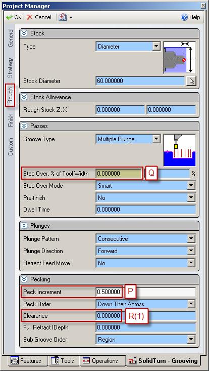
130 125

131 12.4. Threading cycle Introduction In ESPRIT, on the Strategy tab of the SolidTurn Threading operation page, set Canned Cycle to Single Path to trigger the G76 multiple repetitive cycle output. If you set this parameter to Off, the threading cycle will be output with G32 or G34 if Lead Variation is different from 0. When Canned Cycle is set to Multiple Path, the threading cycle will be output with G92. Information about some of the parameters to enter for the following cycles: The lead of the thread F will be output as entered in ESPRIT. The angle of shift of the thread cutting start angle Q will be output as entered in ESPRIT. The cut speed S can be specified on the General tab of the operation. 126
. 12.4.2. Threading with canned cycle set to single path G76 P(1) Q(1) R(1) ; G76 X_ Z_ R(2) P(2) Q(2) F_ ; 127")
132 On the Strategy tab, if you set the Lead-Out Type to Chamfer and the Chamfer Length greater than 0, you will have M23 (chamfer ON) output prior to the G76 or G92 commands. With a different lead-out set, the M-code output will be M24 (chamfer OFF) Threading with canned cycle set to single path G76 P(1) Q(1) R(1) ; G76 X_ Z_ R(2) P(2) Q(2) F_ ; 127
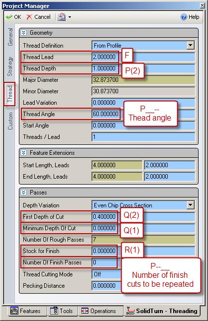
133 128

134 R(1), Q(1), P(2) and Q(2) will be output as entered in ESPRIT Threading with canned cycle set to off Threading with canned cycle set to off, lead variation set to 0: G32 X_ Z_ F_ Q_ ; 129

135 Threading with canned cycle set to off, lead variation different from 0: G34 X_ Z_ F_ K_ Q_ ; 130
136 K will be output as entered in ESPRIT Threading with canned cycle set to multiple path The post processor will automatically adjust the output if you are cutting a straight or a tapered thread. Note: If you set the Lead-In Type to Feed or Chamfer or the Lead-Out Type to Feed, you will get the following error message in your NC code: ERROR: WRONG LEAD-IN OR LEAD-OUT TYPE SPECIFIED. 131

137 Straight thread cutting: G92 X_ Z_ F_ Q_ ; 132
138 Tapered thread cutting: G92 X_ Z_ R_ F_ ; 133

139 13. Hole machining canned cycles and other functionalities for drilling cycles Introduction Hole machining programs are so complicated, specified in several blocks. A hole machining canned cycle, however, allows the hole machining to be programmed in one block with the appropriate G codes below: The Face Hole Machining Canned Cycle: Hole machining is executed by the Z-axis with positioning executed by the combination of the X-, C- (C-axis specifications only) and Y-axes (Y-axis specifications only). The Side Hole Machining Canned Cycle: Hole machining is executed by the X-axis with positioning executed by the combination of the Z-, C- (C-axis specifications only) and Y-axes (Y-axis specifications only). In ESPRIT, you can choose between the different drilling canned cycles using the Cycle Type pull-down on the Drill tab for the SolidTurn Drilling cycle: On the Drill tab for the SolidMillTurn Drilling cycle: 134

140 On the Wrap Drill tab for the SolidMillTurn Wrap Drilling cycle: 135

141 Also make sure to set Canned Cycle to Yes: 136

142 Note that the correct G-code for the drill canned cycle will be output based on the cycle type (SolidTurn Drilling or SolidMillTurn Drilling/Wrap Drilling) and the orientation of the tool in use: you will not need to choose between side or face hole machining canned cycle, the post processor will do it for you. Information about some of the parameters to enter for the following cycles: For G83 / G87, the depth of cut per one infeed motion Q is an unsigned value, in radius for side drilling. Specify Q in mm, it will then be output in units of mm without decimal point. For example, if you enter 2 for Q in ESPRIT, the output will be in the NC code Q2000. For G74, the depth of cut per one infeed motion Q will be output as entered in ESPRIT. Enter the dwell P in s, it will then be output in units of 0.001s without decimal point. For example, if you enter 1.5 for P in ESPRIT, the output will be in the NC code P1500. The feedrate F (and the cut speed S) can be specified on the General tab of the operation. 137
 C_ Z_ R_ Q_ P_ F_ ; G87 Z_ (Y_) C_ X_ R_ Q_ P_ F_ ; 138")
143 13.2. Face and side high-speed deep hole drilling / Face and side deep hole drilling / Deep hole drilling in turning mode / Deep hole drilling with G Face and side high-speed deep hole drilling (G83/G87) (Parameter #8115 = 1) CAUTION!!! Use SolidMillTurn Drilling or SolidMillTurn Wrap Drilling G83 X_ (Y_) C_ Z_ R_ Q_ P_ F_ ; G87 Z_ (Y_) C_ X_ R_ Q_ P_ F_ ; 138
 C_ Z_ R_ Q_ P_ F_ ; G87 Z_ (Y_) C_ X_ R_ Q_ P_ F_ ; 13.2.3. Deep hole drilling in turning mode CAUTION!")
144 Face and side deep hole drilling (G83/G87) (Parameter #8115 = 0) CAUTION!!! Use SolidMillTurn Drilling or SolidMillTurn Wrap Drilling G83 X_ (Y_) C_ Z_ R_ Q_ P_ F_ ; G87 Z_ (Y_) C_ X_ R_ Q_ P_ F_ ; Deep hole drilling in turning mode CAUTION!!! Use SolidTurn Drilling If you want to perform a deep hole drilling cycle with the SolidTurn Drilling operation, set the Cycle Type to Peck and Canned Cycle to No. No canned cycle is supported for the turn deep hole drilling cycle. The code will be output with linear G01 moves. 139

145 Note: If you omit to set Canned Cycle to No, you will get the following error message in your NC code: ERROR: CANNED CYCLE NOT SUPPORTED FOR LATHE CYCLE Deep hole drilling with G74 CAUTION!!! Use SolidTurn Drilling G74 R(1) G74 Z_ Q_ F_ ; On the SolidTurn Drilling cycle, set the Cycle Type to Drill or Peck 2 to output your drilling cycle with G
 so the hole will be drilled in one infeed motion.")

146 If you select Drill, the depth of cut per one infeed motion Q will be set to the total depth of cut plus 5 mm (or plus 0.2 in) so the hole will be drilled in one infeed motion. If you select Peck 2, you will be able to specify the value of Q that will be output in the NC code: R(1) corresponds to return amount. It will be output as entered in ESPRIT when Peck 2 is selected. R0.0 will be output when Drill is selected. 141
 C_ Z_ R_ P_")
147 13.3. Face and side spot drilling (G83/G87) CAUTION!!! Use SolidMillTurn Drilling or SolidMillTurn Wrap Drilling G83 X_ (Y_) C_ Z_ R_ P_ F_ ; G87 Z_ (Y_) C_ X_ R_ P_ F_ ; 142

148 13.4. Tapping at center of spindle (G32) CAUTION!!! Use SolidTurn Drilling G32 Z_ F_ ; If you set the Cycle Type to Tap on the SolidTurn Drilling cycle, the tapping canned cycle will be output with G

149 Note: The direction of the tap is controlled by the tool spindle direction (clockwise or counterclockwise) set on the tool page Face and side synchronized tapping / Face and side synchronized reverse tapping Restriction of synchronized tapping CAUTION!!! During the synchronized tapping cycle, the maximum speeds for the rotary tool is 3000 min -1. If the maximum speed for the rotary tool holder is less than the above, specify a speed that is less than the maximum speed for the holder. Note: Synchronized tapping can only be used with milling drilling operations. On the SolidTurn Drilling operation, if you set Cycle Type to: Tap, the code will be output with G32 (tapping at center of spindle). Tap 2, you will get the following error message in your NC code: ERROR: CANNED CYCLE NOT SUPPORTED FOR LATHE CYCLE. 144
150 Face and side synchronized tapping (M329 G84/M329 G88) CAUTION!!! Use SolidMillTurn Drilling or SolidMillTurn Wrap Drilling M329 S_ ; G84 X_ (Y_) C_ Z_ R_ P_ F_ ; M329 S_ ; G88 Z_ (Y_) C_ X_ R_ P_ F_ ; 145
151 Face and side synchronized reverse tapping (M329 G84.1/M329 G88.1) CAUTION!!! Use SolidMillTurn Drilling or SolidMillTurn Wrap Drilling M329 S_ ; G84.1 X_ (Y_) C_ Z_ R_ P_ F_ ; M329 S_ ; G88.1 Z_ (Y_) C_ X_ R_ P_ F_ ; 146
152 147
153 13.6. Face and side boring / Boring in turning mode Face and side boring (G85/G89) CAUTION!!! Use SolidMillTurn Drilling or SolidMillTurn Wrap Drilling G85 X_ (Y_) C_ Z_ R_ P_ F_ ; G89 Z_ (Y_) C_ X_ R_ P_ F_ ; 148

154 Boring in turning mode CAUTION!!! Use SolidTurn Drilling If you want to perform a boring cycle with the SolidTurn Drilling operation, set the Cycle Type to Bore and Canned Cycle to No. No canned cycle is supported for the turn boring cycle. The code will be output with linear G01 moves. 149

155 Note: If you omit to set Canned Cycle to No, you will get the following error message in your NC code: ERROR: CANNED CYCLE NOT SUPPORTED FOR LATHE CYCLE Spindle / Rotary Tool Spindle Simultaneous Operation Mode CAUTION!!! Use SolidTurn Drilling M90 S_ ; M91; M290 S_ ; M291; The M90 and M290 (for NLX configuration) commands is used to rotate the spindle and the rotary tool simultaneously to machine a hole at the center of the spindle (workpiece) at a proper cutting speed if necessary cutting speed cannot be obtained by rotating only the spindle or the rotary tool. On the Custom tab of the SolidTurn Drilling operation, set Simultaneous Operation (Custom Setting 6) to 90 to trigger the output of the M90 command. 150
 the percentage of the total speed you want to apply to the rotary tool.")
156 On the General tab, set in Speed RPM the desired total speed, which mean speed of the turning spindle plus speed of the rotary tool. You can then specify with Speed Percentage (Custom Setting 7) the percentage of the total speed you want to apply to the rotary tool. Example: If you set the Speed RPM to 6000 and Speed Percentage to 30, the spindle speed will be % * 6000 = 4200 rpm and the rotary tool speed will be 6000 * 30% = 1800 rpm. Notes: Set on the General tab, the Feed Unit to Per Minute: You can determine the feedrate of the tool assuming the spindle speed of 6000 min 1, which is the sum of the turning spindle speed (4200 min -1 ) and the rotary tool speed (1800 min 1 ). On the General tab, make sure to change the Maximum RPM value according to the specified Speed RPM value. If Speed RPM is set to 6000 rpm but Maximum RPM to 5000 rpm, the output will be computed using 5000 rpm, as a safety. The direction of rotation has to be specified on the Tool page by the pull-down Spindle Direction. 151

157 14. 4-axis wrap milling cycles with interpolation Introduction The NC code can be very long for wrap milling operations using the C-axis. But it can be shorten by turning on the interpolation Cylindrical interpolation The cylindrical interpolation can be turned on the SolidMillTurn Wrap Pocketing and Wrap Contouring pages. 152

 on the Wrap tab in the Working Diameter field of the operation pages: Cylindrical interpolation is")
158 On the Wrap tab of the operation pages, set Cylindrical Interpolation to Yes to output 4- axis wrap milling operations with cylindrical interpolation. It will be turned on in the NC code by G07.1 C_ and turned off by G07.1 C0. C corresponds to the radius of the workpiece (groove bottom). It can be specified (as a diameter value) on the Wrap tab in the Working Diameter field of the operation pages: Cylindrical interpolation is used when cutting on cylinder circumference. Programming is made assuming a plane by developing the cylinder circumference into the plane. 153
159 Using cylindrical interpolation can shorten the program length because ESPRIT outputs the circular motions in the cylindrical plane. Without cylindrical interpolation, circular motions in the cylindrical plane are approximated by small linear moves (quality varies with the tolerance of the operation page) Polar coordinate interpolation (Notching) The polar coordinate interpolation can be turned on the SolidMillTurn Wrap Face Pocketing and Wrap Face Contouring pages. On the Strategy tab of the operation pages, set Polar Interpolation to Yes to output rotary face milling operations with polar interpolation. 154
 (C = Y distance), instead of XC (C in degrees).")
160 It will be turned on in the NC code by G112 and turned off by G113. Tool positions are output in rectangular coordinate system (X; C) (C = Y distance), instead of XC (C in degrees). The work system rotates to the start C position of the operation. The start point is always at C (Y distance) =

161 15. Other Functionalities Tailstock Introduction When machining long work pieces with the Mori Seiki NZX & NLX machines, it is sometimes beneficial to use a tailstock to support the workpiece while you are machining. 156
162 Note: For NZX configuration, based on the type of tailstock and machine, you will have to program your tailstock on head 1 or on head 2 (see part Type of tailstock installed on the machine): NZX2500 NZX4000 NZX6000 Servo driven tailstock HEAD1 - HEAD1 Carriage direct-coupled tailstock HEAD1 HEAD2 HEAD2 For NLX configuration, based on the type of tailstock installed on the machine, the NC output will differ. The type of tailstock is defined in the Machine Setup in ESPRIT (see part Type of tailstock installed on the machine) Defining the tailstock in the Machine Setup Open the Machine Setup page and navigate to the Assembly tab. Click on Tailstock to view the Tailstock Properties window. Under Type select Independent. It is also possible to define specific geometric properties of the tailstock in this section. Check Custom Tailstock to use the geometry from the Machine Setup as the tailstock. Machine Setup Assembly Page: 157
 for Turret Name for NZX configuration.")
163 Creating the tailstock operation To create a Tailstock operation, click on the Tailstock operation on the SolidTurn toolbar. On the Tailstock tab, select Upper Turret or Lower Turret (based on type of tailstock and machine) for Turret Name for NZX configuration. With the Tailstock pull-down, you can select whether the operation is an Engage or Disengage. This tells the machine whether you would like the tailstock to engage with the workpiece or if you would like it to retract from the workpiece after machining has been completed. With Position X, Y, Z, set the reference tailstock engage point. This is the point that the tailstock will engage the part at during simulation. 158
 field of the operation page, enter the position of the tailstock (machine coordinate value) V for NZX & NLX with carriage directcoupled tailstock")
164 In the Dwell Time field, you can specify a dwell that will be output at the end of the tailstock engagement. In the Tailstock Position (Custom Setting 1) field of the operation page, enter the position of the tailstock (machine coordinate value) V for NZX & NLX with carriage directcoupled tailstock configurations. The tailstock will travel to this position. Note that you can enter a positive or negative value; the output position will always be negative since it is output in the machine work coordinate. 159

165 15.2. Independent steady rest Introduction When machining long work pieces with the Mori Seiki NZX & NLX machines, it is sometimes beneficial to use an independent steady rest to support the workpiece while you are machining Defining the steady rest On the Steady Rest Utility of the MoriSeiki AddIn, you will be able to create your independent steady rest. 160

166 Note: Please refer to your MoriSeiki AddIn Manual to have detailed instructions on how to create the steady rest with this utility Creating the steady rest operation To create a Steady Rest operation, click on the Steady Rest operation on the SolidTurn toolbar. On the Steady Rest tab, select Lower Turret for Turret Name since the steady rest is controlled by the lower turret for NZX configuration. 161
 V. The steady rest will travel to this position.")
167 In the G479V Value (Custom Setting 1) field of the operation page, enter the position of the steady rest (machine coordinate value) V. The steady rest will travel to this position. 162

168 When you click OK, a new window will pop up that allows you to create the path for your steady rest. In this window you will have several options to create your steady rest operation: Rapid or Feed moves: Use your cursor to select a point to move to and then click the Apply button to record that move; Note that Rapid and Feed modes will produce the same NC code since the steady rest is only moved using a macro (G479 V) Open (M340) and Close (M341) at specified diameters: To record an open or close move, enter the diameter in the field next to the button (Open or Close) you want to use and simply click on the respective button Dwell times and Stop codes: Not used Note that while programming the steady rest movements, you can use Back if you did a mistake and need to undo the last created entry. When you are finished programming your steady rest movements, click on Cycle Stop to close the window and create your Steady Rest operation. 163
 NZX6000 machines support Long Boring Bar (LBB) specification.")
169 In the NC code (of upper and lower turrets for NZX configuration), the steady rest coolant code (ON/OFF) will automatically be output along with regular coolant codes while the steady rest is closed. G361 M_. ; Long Boring Bar (for NZX6000 configuration only) NZX6000 machines support Long Boring Bar (LBB) specification. LBB cannot be mounted on standard tool holders on the turret due to their size. LBB holders are directly mounted on the X-axis of the upper turret. They have an automatic tool changer. Three LBB can be placed in the tool changer. For LBB specification, tool station 12 on the upper turret is dedicated for LBB mounting. Once a LBB is mounted in station 12, the upper turret cannot be indexed. Upper turret can only be indexed when dummy holder is mounted in station

170 The LBB tool change command G-code (G361) is used to call the holder in the LBB magazine. The different options for M_ are: M1: Dummy holder on LBB magazine 1 M2: LBB holder 1 on LBB magazine 2 M3: LBB holder 2 on LBB magazine 3 M4: LBB holder 3 on LBB magazine 4 In ESPRIT, to program an operation using a LBB tool, simply create your LBB in station 13, 14 or 15. Station 13 will contain LBB holder 1 (located on LBB magazine 2), station 14 will contain LBB holder 2 (located on LBB magazine 3) and station 15 will contain LBB holder 3 (located on LBB magazine 4). The corresponding G361 M_ codes will be output in the NC code. Note that in ESPRIT, you need to set your tool number to the magazine number For example for magazine 2, you would set your tool number to 14 (12+2). 165
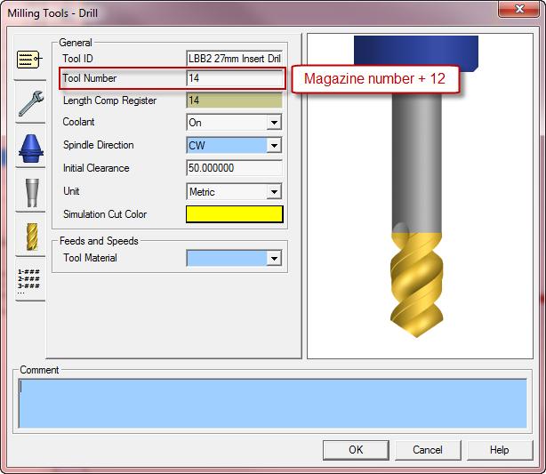
171 166
 NZX Head 1 & 2 / NLX: Used for Tailstock cycle 161 Steady Rest position (G479) NZX Head 2 / NLX:")
172 When switching to a regular tool holder (located in station 1 to 11), G361 M1 will automatically be output in the NC code to load the dummy holder prior to index the upper turret to the regular tool. 16. Custom Settings index On operation pages See page Use Comments 158 Tailstock position (G479) NZX Head 1 & 2 / NLX: Used for Tailstock cycle 161 Steady Rest position (G479) NZX Head 2 / NLX: Used for Steady Rest cycle Custom Setting 1 NZX Head 1 & 2 / NLX: Used for Tailstock 62 Park turret with G53 cycle / Used for Park cycle 110 Workpiece pushing check (G38) NLX: Used for Part pickup cycle 48 Output of rapid moves (G00) with linear interpolation moves (G01 F) NZX Head 1 / NLX: Used for all milling cycles 64 Output stop coolant code (M09) NZX Head 1 & 2 / NLX: Used for Park cycle Custom Setting 2 NLX: Used for Part pickup cycle / Goes with 110 B-axis retraction stroke Custom Setting 1 Custom Setting B-axis feedrate NLX: Used for Part pickup cycle / Goes with Custom Setting 1 167
Table of Contents. Preface 9 Prerequisites 9. Key Concept 1: Know Your Machine From A Programmer s Viewpoint 13. Table of Contents
 Preface 9 Prerequisites 9 Basic machining practice experience 9 Controls covered 10 Limitations 10 Programming method 10 The need for hands -on practice 10 Instruction method 11 Scope 11 Key Concepts approach
Figure 1: NC Lathe menu
 Click To See: How to Use Online Documents SURFCAM Online Documents 685)&$0Ã5HIHUHQFHÃ0DQXDO 5 /$7+( 5.1 INTRODUCTION The lathe mode is used to perform operations on 2D geometry, turned on two axis lathes.
Motion Manipulation Techniques
 Motion Manipulation Techniques You ve already been exposed to some advanced techniques with basic motion types (lesson six) and you seen several special motion types (lesson seven) In this lesson, we ll
527F CNC Control. User Manual Calmotion LLC, All rights reserved
 527F CNC Control User Manual 2006-2016 Calmotion LLC, All rights reserved Calmotion LLC 21720 Marilla St. Chatsworth, CA 91311 Phone: (818) 357-5826 www.calmotion.com NC Word Summary NC Word Summary A
Table of Contents. Table of Contents. Preface 11 Prerequisites... 12
 Table of Contents Preface 11 Prerequisites... 12 Basic machining practice experience... 12 Controls covered... 12 Limitations... 13 The need for hands -on practice... 13 Instruction method... 13 Scope...
CAD/CAM/CAE Computer Aided Design/Computer Aided Manufacturing/Computer Aided Manufacturing. Part-10 CNC Milling Programming
 CAD/CAM/CAE Computer Aided Design/Computer Aided Manufacturing/Computer Aided Manufacturing Part-10 CNC Milling Programming To maximize the power of modern CNC milling machines, a programmer has to master
Figure 1: NC EDM menu
 Click To See: How to Use Online Documents SURFCAM Online Documents 685)&$0Ã5HIHUHQFHÃ0DQXDO 6 :,5(('0 6.1 INTRODUCTION SURFCAM s Wire EDM mode is used to produce toolpaths for 2 Axis and 4 Axis EDM machines.
HAAS AUTOMATION, INC.
 PROGRAMMING WORKBOOK HAAS AUTOMATION, INC. 2800 Sturgis Rd. Oxnard, CA 93030 January 2005 JANUARY 2005 PROGRAMMING HAAS AUTOMATION INC. 2800 Sturgis Road Oxnard, California 93030 Phone: 805-278-1800 www.haascnc.com
HAAS AUTOMATION, INC.
 PROGRAMMING WORKBOOK HAAS AUTOMATION, INC. 2800 Sturgis Rd. Oxnard, CA 93030 JANUARY 2005 . JANUARY 2005 PROGRAMMING HAAS AUTOMATION INC. 2800 Sturgis Road Oxnard, California 93030 Phone: 805-278-1800
SHOP NOTES. GPocket Guide and Reference Charts. for CNC Machinists. Made in the U.S.A.
 SHOP NOTES GPocket Guide and Reference Charts for CNC Machinists Made in the U.S.A. WHAT S INSIDE THIS BOOKLET? Decimal Equivalent Chart / Millimeter to Inch Chart Haas Mill G-Codes / Haas Mill M-Codes
Preview Sample. Date: September 1, 2010 Author: Matthew Manton and Duane Weidinger ISBN:
 Computer Numerical Control Workbook Generic Lathe Published by CamInstructor Incorporated 330 Chandos Crt. Kitchener, Ontario N2A 3C2 www.caminstructor.com Date: September 1, 2010 Author: Matthew Manton
Table 5.1: Drilling canned cycles. Action at the bottom of the hole. Cancels drilling canned cycle Intermittent or continuous feed.
 5.18 CANNED CYCLES FOR DRILLING On a lathe, equipped with live tooling (which allows a tool, obviously a drilling or a similar tool, to rotate at the specified RPM, as in a milling machine) and an additional
SAMSUNG Machine Tools PL 1600G/1600CG GANG CNC TURNING CENTER
 SAMSUNG Machine Tools PL 1600G/1600CG GANG CNC TURNING CENTER SAMSUNG Machine Tools GANG CNC TURNING CENTER PL 1600G/1600CG Best fit on Both High Speed Machining and Automation System. Automation Ready
PROGRAMMING January 2005
 PROGRAMMING January 2005 CANNED CYCLES FOR DRILLING TAPPING AND BORING A canned cycle is used to simplify programming of a part. Canned cycles are defined for the most common Z-axis repetitive operation
Miyano Evolution Line
 Evolution Line CNC Turning center with 2 spindles, 2 turrets and 1 -axis slide BNJ-34/42/51 "Evolution and Innovation" is the Future What could not be done can be done. -axis movement is added to the traditional
WINMAX LATHE NC PROGRAMMING
 WINMAX LATHE NC PROGRAMMING Dual-screen and Max Consoles for Hurco Turning Centers April 2013 704-0115-309 Revision A The information in this document is subject to change without notice and does not represent
Fixed Headstock Type CNC Automatic Lathe
 Fixed Headstock Type CNC Automatic Lathe MSY The BNE series is renowned for its high rigidity, heavy cutting capability and outstanding precision. The new MSY model extends the ability of the BNE series
COMPUTER INTEGRATED MANUFACTURING LABORATORY (14AME31)
") COMPUTER INTEGRATED MANUFACTURING LABORATORY (14AME31) (For III B.Tech - II SEM- Mechanical Engineering) DEPARTMENT OF MECHANICAL ENGINEERING SRI VENKATESWARA COLLEGE OF ENGINEERING & TECHNOLOGY R.V.S
COMPUTER INTEGRATED MANUFACTURING LABORATORY (14AME31) (For III B.Tech - II SEM- Mechanical Engineering) DEPARTMENT OF MECHANICAL ENGINEERING SRI VENKATESWARA COLLEGE OF ENGINEERING & TECHNOLOGY R.V.S
FNL-220Y / 220SY / 200LS Series CNC Turning-Milling Machines Linear Way
 RICH WELL 206.0 Dimensions R450 E FNL-220Y / 220SY / 200LS Series CNC Turning-Milling Machines Linear Way 20 C D Chip conveyor 092 H G B 46 575 A F Unit:mm A B C D E F G H FNL220LSY/FNL220LY 952 2946 2700
WINMAX LATHE NC PROGRAMMING
 WINMAX LATHE NC PROGRAMMING Dual-screen and Max Consoles for Hurco Turning Centers March 2012 704-0115-306 Revision A The information in this document is subject to change without notice and does not represent
SL 3500Y series Y-AXIS HORIZONTAL TURNING CENTER
 NC Specifications / FANUC Series Controlled axes Item 3-axis(X,Y,Z) Description Controlled axes Max. simultaneously controlled axes Least input increment Positioning(G00) / Linear Interpolation(G01) Circular
for CNC Lathe Mori Advanced Programming Production System User-friendly features and high reliability now standard for all machines.
 THE MACHINE TOOL COMPANY for CNC Lathe Mori Advanced Programming Production System User-friendly features and high reliability now standard for all machines. To standardize operation among the many machine
The enriched system configuration designed based on the loader head accommodates a wide range of automation needs.
 CNC Lathe These are high-precision chucking machines equipped with a general-purpose in-machine loader head. The loading time is shortened substantially through coordinated operation of the loader head
Turning and Lathe Basics
 Training Objectives After watching the video and reviewing this printed material, the viewer will gain knowledge and understanding of lathe principles and be able to identify the basic tools and techniques
Lathe Series Training Manual. Haas CNC Lathe Programming
 Haas Factory Outlet A Division of Productivity Inc Lathe Series Training Manual Haas CNC Lathe Programming Revised 050914; Rev3-1/29/15; Rev4-31017 This Manual is the Property of Productivity Inc The document
NC Programming for PUMA Turning Centers Equipped with Live Tools, Sub Spindle, Y- Axis
 NC Programming for PUMA Turning Centers Equipped with Live Tools, Sub Spindle, Y- Axis For PUMA Turning Centers 200M, 200MS, 230M, 230MS, 240M, 240MS, 300M, 300MS 1500Y/SY, 2000Y/SY, 2500Y/SY 1 TABLE OF
CNC Machinery. Module 4: CNC Programming "Turning" IAT Curriculum Unit PREPARED BY. August 2009
 CNC Machinery Module 4: CNC Programming "Turning" PREPARED BY IAT Curriculum Unit August 2009 Institute of Applied Technology, 2009 2 Module 4: CNC Programming "Turning" Module 4: CNC Programming "Turning"
Fixed Headstock Type CNC Automatic Lathe
 Fixed Headstock Type CNC Automatic Lathe The BNA series packs sophisticated functions and high accuracy into a space-saving compact body. The BNA series aims to set the new standard for machines for cutting
Prismatic Machining Preparation Assistant
 Prismatic Machining Preparation Assistant Overview Conventions What's New Getting Started Open the Design Part and Start the Workbench Automatically Create All Machinable Features Open the Manufacturing
Touch Probe Cycles TNC 426 TNC 430
 Touch Probe Cycles TNC 426 TNC 430 NC Software 280 472-xx 280 473-xx 280 474-xx 280 475-xx 280 476-xx 280 477-xx User s Manual English (en) 6/2003 TNC Model, Software and Features This manual describes
Manual Guide i. Lathe Training Workbook. For. Lathe Turning & Milling
 Manual Guide i Lathe Training Workbook For Lathe Turning & Milling A-816A Hardinge Inc., 2008 Part No. A A-0009500-0816 Litho in USA June 2008 2 Section Pages Section One: Basic Machine Operations Sequence
FANUC SERIES 21i/18i/16i TA. Concise guide Edition 03.01
 FANUC SERIES 21i/18i/16i TA Concise guide Edition 03.01 0.1 GENERAL INDEX- CONCISE GUIDE FOR PROGRAMMER PAGE PAR. CONTENTS 7 1.0 FOREWORD 8 2.0 NC MAIN FUNCTIONS AND ADDRESSES 8 2.1 O Program and sub-program
Mach4 CNC Controller Lathe Programming Guide Version 1.0
 Mach4 CNC Controller Lathe Programming Guide Version 1.0 1 Copyright 2014 Newfangled Solutions, Artsoft USA, All Rights Reserved The following are registered trademarks of Microsoft Corporation: Microsoft,
SAMSUNG Machine Tools PL2000SY CNC TURNING CENTER
 SAMSUNG Machine Tools CNC TURNING CENTER SAMSUNG'S Advanced Engineering and Machine Design Cast iron structure for superior dampening characteristics and thermal displacement Rigid 30 degree slant bed
Computer Numeric Control
 Computer Numeric Control TA202A 2017-18(2 nd ) Semester Prof. J. Ramkumar Department of Mechanical Engineering IIT Kanpur Computer Numeric Control A system in which actions are controlled by the direct
SAMSUNG Machine Tools
 NC Unit Specifications / FANUC Series Controlled axis Operation functions Interpolation functions Feed function Spindle function Tool functions Program input Setting and display Data input/output Max.
LinuxCNC Help for the Sherline Machine CNC System
 WEAR YOUR SAFETY GLASSES FORESIGHT IS BETTER THAN NO SIGHT READ INSTRUCTIONS BEFORE OPERATING LinuxCNC Help for the Sherline Machine CNC System LinuxCNC Help for Programming and Running 1. Here is a link
PL 35/35M/40 CNC TURNING CENTER
 NC Specifications / FANUC Series Controlled axis Operation functions Interpolation functions Feed function Spindle function Tool functions Program input Setting and display Data input/output 본사및공장 Max.
KDL 30M HORIZONTAL TURNING CENTER
 HORIZONTAL TURNING CENTER with LIVE TOOLING KEY FEATURES 12 Chuck BOX Ways Turret Style Tooling Slant Bed Construction Live Tooling Maximum Swing 610mm (24.02 ) Maximum Cutting Diameter 420mm (16.54 )
GE Fanuc Automation. Symbolic CAP T C/Y Axis Module V1. Computer Numerical Control Products. Operator s Manual
 GE Fanuc Automation Computer Numerical Control Products Symbolic CAP T C/Y Axis Module V1 Operator s Manual GFZ-62824EN-1/01 January 1999 Warnings, Cautions, and Notes as Used in this Publication GFL-001
Block Delete techniques (also called optional block skip)
") Block Delete techniques (also called optional block skip) Many basic courses do at least acquaint novice programmers with the block delete function As you probably know, when the control sees a slash code
Block Delete techniques (also called optional block skip) Many basic courses do at least acquaint novice programmers with the block delete function As you probably know, when the control sees a slash code
G02 CW / G03 CCW Circular Interpolation Motion (Group 01) - Mill
 - Mill") Haas Technical Documentation G02 CW / G03 CCW Circular Interpolation Motion (Group 01) - Mill Scan code to get the latest version of this document Translation Available G02 CW / G03 CCW Circular Interpolation
Haas Technical Documentation G02 CW / G03 CCW Circular Interpolation Motion (Group 01) - Mill Scan code to get the latest version of this document Translation Available G02 CW / G03 CCW Circular Interpolation
Typical Parts Made with These Processes
 Turning Typical Parts Made with These Processes Machine Components Engine Blocks and Heads Parts with Complex Shapes Parts with Close Tolerances Externally and Internally Threaded Parts Products and Parts
1640DCL Digital Control Lathe
 1640DCL Digital Control Lathe MACHINE SPECIFICATIONS Multiple Function CNC Lathe 1. Manual Hand wheel Operation 2. CNC G-Code Operation 16.1 swing over bed, 8.6 swing over cross-slide 2.05 diameter hole
VMC Series II Vertical Machining Centers PROGRAMMER S MANUAL. Equipped with the Hardinge / Fanuc System II, Fanuc 0i-M, or Fanuc 18-MC Control
 PROGRAMMER S MANUAL VMC Series II Vertical Machining Centers Equipped with the Hardinge / Fanuc System II, Fanuc 0i-M, or Fanuc 18-MC Control Revised: July 26, 2004 Manual No. M-377B Litho in U.S.A. Part
Prof. Steven S. Saliterman Introductory Medical Device Prototyping
 Introductory Medical Device Prototyping Department of Biomedical Engineering, University of Minnesota http://saliterman.umn.edu/ Images courtesy of Haas You must complete safety instruction before using
Techniques With Motion Types
 Techniques With Motion Types The vast majority of CNC programs require but three motion types: rapid, straight line, and circular interpolation. And these motion types are well discussed in basic courses.
Touch Probe Cycles itnc 530
 Touch Probe Cycles itnc 530 NC Software 340 420-xx 340 421-xx User s Manual English (en) 4/2002 TNC Models, Software and Features This manual describes functions and features provided by the TNCs as of
Lathe Series Training Manual. Live Tool for Haas Lathe (including DS)
") Haas Factory Outlet A Division of Productivity Inc Lathe Series Training Manual Live Tool for Haas Lathe (including DS) Created 020112-Rev 121012, Rev2-091014 This Manual is the Property of Productivity
Haas Factory Outlet A Division of Productivity Inc Lathe Series Training Manual Live Tool for Haas Lathe (including DS) Created 020112-Rev 121012, Rev2-091014 This Manual is the Property of Productivity
CNC Programming Guide MILLING
 CNC Programming Guide MILLING Foreword The purpose of this guide is to help faculty teach CNC programming without tears. Most books currently available on CNC programming are not only inadequate, but also
SL 6500 series CNC TURNING CENTER. NC Unit Specifications / FANUC Series. Item Specification 0i-TF
 NC Unit Specifications / FANUC Series Controlled axis Operation functions Interpolation functions Feed function Spindle function Tool functions Program input Setting and display Data input/output Max.
CNC Turning Training CNC MILLING / ROUTING TRAINING GUIDE. Page 1
 CNC Turning Training www.denford.co.uk Page 1 Table of contents Introduction... 3 Start the VR Turning Software... 3 Configure the software for the machine... 4 Load your CNC file... 5 Configure the tooling...
SLV 1000/1000M VERTICAL TURNING CENTER
 NC Specifications / FANUC Series Controlled axis Operation functions Interpolation functions Feed function Spindle function Tool functions Program input Setting and display Max. feed axes Feed axes Item
CNC LATHE TURNING CENTER PL-20A
 CNC LATHE TURNING CENTER PL-20A CNC LATHE TURNING CENTER For High Precision, High Speed and High Productivity MAIN FEATURE Introducing the latest and strongest CNC Lathe PL20A that has satisfied the requirements
User s Manual Cycle Programming TNC 320. NC Software
 User s Manual Cycle Programming TNC 320 NC Software 340 551-04 340 554-04 English (en) 9/2009 About this Manual The symbols used in this manual are described below. This symbol indicates that important
Prof. Steven S. Saliterman Introductory Medical Device Prototyping
 Introductory Medical Device Prototyping Department of Biomedical Engineering, University of Minnesota http://saliterman.umn.edu/ You must complete safety instruction before using tools and equipment in
SINUMERIK System 800 Cycles, User Memory Submodule 4
 SINUMERIK System 800 Cycles, User Memory Submodule 4 User Documentation SINUMERIK System 800 Cycles, User Memory Submodule 4 Programming Guide User Documentation Valid for: Control Software version SINUMERIK
Prasanth. Lathe Machining
 Lathe Machining Overview Conventions What's New? Getting Started Open the Part to Machine Create a Rough Turning Operation Replay the Toolpath Create a Groove Turning Operation Create Profile Finish Turning
for SUNNEN TUBE HONING MACHINES HTC SERIES Version: VC-40 50/ VCSC11 30, V -6.43/44b File: CME-V643 Date: 15 March, 2006
 I-HTC-120 Control MANUAL for SUNNEN TUBE HONING MACHINES HTC SERIES Version: VC-40 50/ VCSC11 30, V -6.43/44b File: CME-V643 Date: 15 March, 2006 READ THE FOLLOWING INSTRUCTIONS THOROUGHLY AND CAREFULLY
SAMSUNG Machine Tools PL35 CNC TURNING CENTER
 SAMSUNG Machine Tools PL35 CNC TURNING CENTER SAMSUNG'S Advanced Engineering and Machine Design Cast iron structure for superior dampening characteristics and thermal displacement Rigid 45 degree slant
High Precision CNC Lathe
 High Precision CNC Lathe Designed for high-precision machining of smalldiameter workpieces, this machine has a wing type fixed spindle for low thermal influence installed on a thermally symmetrical machine
Computer Aided Manufacturing
 Computer Aided Manufacturing CNC Milling used as representative example of CAM practice. CAM applies to lathes, lasers, waterjet, wire edm, stamping, braking, drilling, etc. CAM derives process information
4. (07. 03) CNC TURNING CENTER
 CNC TURNING CENTER") 4. (07. 0) CNC TURNING CENTER World Top Class Quality HYUNDAI-KIA Machine Tool High Speed, High Accuracy, High Rigidity CNC Turning Center New Leader of Medium and Large Size CNC Turning Center More Powerful
4. (07. 0) CNC TURNING CENTER World Top Class Quality HYUNDAI-KIA Machine Tool High Speed, High Accuracy, High Rigidity CNC Turning Center New Leader of Medium and Large Size CNC Turning Center More Powerful
MTC200 Description of NC Cycles. Application Manual SYSTEM200 DOK-MTC200-CYC*DES*V22-AW02-EN-P
 X rapid feed feed first feed * n... appr.. * appr.. * 1... end point Z gradient starting point Z end p. X start. p. X Z MTC200 Description of NC Cycles Application Manual SYSTEM200 About this Documentation
Mill Series Training Manual. Haas CNC Mill Programming
 Haas Factory Outlet A Division of Productivity Inc Mill Series Training Manual Haas CNC Mill Programming Revised 021913 (Printed 02-2013) This Manual is the Property of Productivity Inc The document may
DMG MORI Technology Cycles
 DMG MORI Technology Cycles Complex machining easily realized www.dmgmori.co.jp + DMG MORI Technology Cycles + New solutions making complex machining simpler and quicker DMG MORI SYSTEMS DMG MORI Technology
CNC TURNING CENTER 3. (06. 07) Head Office. Seoul Office. Head Office & Factory. HYUNDAI - KIA MACHINE AMERICA CORP. (New Jersey Office)
 Head Office. Seoul Office. Head Office & Factory. HYUNDAI - KIA MACHINE AMERICA CORP. (New Jersey Office)") CNC TURNING CENTER Head Office Head Office & Factory. (06. 07 Seoul Office HYUNDAI - KIA MACHINE AMERICA CORP. (New Jersey Office HYUNDAI - KIA MACHINE AMERICA CORP. (Chicago Office HYUNDAI - KIA MACHINE
CNC TURNING CENTER Head Office Head Office & Factory. (06. 07 Seoul Office HYUNDAI - KIA MACHINE AMERICA CORP. (New Jersey Office HYUNDAI - KIA MACHINE AMERICA CORP. (Chicago Office HYUNDAI - KIA MACHINE
NUMERICAL CONTROL.
 NUMERICAL CONTROL http://www.toolingu.com/definition-300200-12690-tool-offset.html NC &CNC Numeric Control (NC) and Computer Numeric Control (CNC) are means by which machine centers are used to produce
OmniTurn Start-up sample part
 OmniTurn Start-up sample part OmniTurn Sample Part Welcome to the OmniTum. This document is a tutorial used to run a first program with the OmniTurn. It is suggested before you try to work with this tutorial
DuraTurn Series. CNC Lathe. для получения подробной информации, пожалуйста, напишите нам на почту
 DuraTurn 2030 DuraTurn 2050 DuraTurn 2550 CNC Lathe DuraTurn Series Durable Universal Reliable Affordable Accurate CNC Lathe with Excellent Operability and Machining Capability The DuraTurn series, which
MACHINIST S REFERENCE GUIDE
 MACHINIST S REFERENCE GUIDE Hurco Companies, Inc. One Technology Way / P.O. Box 68180 Indianapolis, IN 46268-0180 800.634.2416 Info@hurco.com HURCO.com Hurco Applications Hotline 317.614.1549 applications@hurco.com
Projects. 5 For each component, produce a drawing showing the intersection BO.O. C'BORE 18 DIA x 5 DEEP FROM SECTION ON A - A
 Projects ~ Figure Pl Project 1 If you have worked systematically through the assignments in this workbook, you should now be able to tackle the following milling and turning projects. It is suggested that
High Precision CNC Lathe
 High Precision CNC Lathe GN3200 High efficiency through space savings A compact design with a total machine width of 700 mm and a floor space requirement of 1.04 m2 has made it possible to shorten production
Lesson 2 Understanding Turning Center Speeds and Feeds
 Lesson 2 Understanding Turning Center Speeds and Feeds Speed and feed selection is one of the most important basic-machining-practice-skills a programmer must possess. Poor selection of spindle speed and
CNC Machinery. Module 5: CNC Programming / Milling. IAT Curriculum Unit PREPARED BY. August 2009
 CNC Machinery Module 5: CNC Programming / Milling PREPARED BY IAT Curriculum Unit August 2009 Institute of Applied Technology, 2009 ATM313-CNC Module 5: CNC Programming / Milling Module Objectives: 1.
PROGRAMMER S MANUAL CNC Lathes Equipped with the GE Fanuc 18T Control
 PROGRAMMER S MANUAL TP1421 CNC Lathes Equipped with the GE Fanuc 18T Control Revised: September 28, 1999 Manual No. M-320A Litho in U.S.A. Part No. M A-0009500-0320 April, 1997 - NOTICE - Damage resulting
WINMAX LATHE OPTIONS Dual-screen and Max Consoles for Hurco Turning Centers
 WINMAX LATHE OPTIONS Dual-screen and Max Consoles for Hurco Turning Centers May 2015 704-0115-409 Revision A The information in this document is subject to change without notice and does not represent
CNC Turning Center with 2 Spindles, 2 Turrets and 1 Y-axis Slide BNE-34/51
 CNC Turning Center with 2 Spindles, 2 Turrets and 1 Y-axis Slide BNE-34/51 "Evolution and Innovation" is the Future The BNE series handles your high value barwork. 2 Miyano BNE-34/51 The BNE Series was
Chapter 22 MACHINING OPERATIONS AND MACHINE TOOLS
 Chapter 22 MACHINING OPERATIONS AND MACHINE TOOLS Turning and Related Operations Drilling and Related Operations Milling Machining Centers and Turning Centers Other Machining Operations High Speed Machining
CNC MULTI-TASKING TURNING CENTER
 PRECISION CNC LATHE CNC MULTITASKING TURNING CENTER CNC GANG / TURRET LATHE SD32 Gang Type Tool Holder Robotic Arm + Turret 3 position ID Tool Holder + Turret Cross Drilling Device + Hydraulic Turret Y
CNC TURNING CENTRES B1200-M-Y
 CNC TURNING CENTRES B1200-M-Y Great versatility and superb chip removal. B1200 2-3 The family of BIGLIA B1200 lathes universally appreciated for their rigidity, accuracy and durability, has been designed
CNC Applications. Programming Machining Centers
 CNC Applications Programming Machining Centers Planning and Programming Just as with the turning center, you must follow a series of steps to create a successful program: 1. Examine the part drawing thoroughly
FBL-250Y/320Y/SY Series. CNC Turning-Milling Machines Linear/Box Way
 FNLY/2Y/SY Series FBLY/2Y/SY Series CNC TurningMilling Machines Linear/Box Way Multifunctional Turning and Milling Excellence FNLY/2Y/SY Linear Way Series FBLY/2Y/SY Box Way Series CNC TurningMilling Machines
Fixed Headstock Type CNC Automatic Lathe
 Fixed Headstock Type CNC Automatic Lathe GTY Configured with two spindles, one turret, 2 x Y axes, gang tools and X3 axis to back spindle, the BNA42GTY can mount up to 45 tools. 3 tool simultaneous cutting
CNC PROGRAMMING WORKBOOK. Sample not for. Distribution MILL & LATHE. By Matthew Manton and Duane Weidinger
 CNC PROGRAMMING WORKBOOK MILL & LATHE By Matthew Manton and Duane Weidinger CNC Programming Workbook Mill & Lathe Published by: CamInstructor Incorporated 330 Chandos Crt. Kitchener, Ontario N2A 3C2 www.caminstructor.com
CAMWorks How To Create CNC G-Code for CO2 Dragsters
 Creating the Left Side Smooth Finish Tool Path. This chapter will focus on the steps for creating the left side smooth finish tool path. The objective of this chapter is to create to an accurate and highly
Basic NC and CNC. Dr. J. Ramkumar Professor, Department of Mechanical Engineering Micro machining Lab, I.I.T. Kanpur
 Basic NC and CNC Dr. J. Ramkumar Professor, Department of Mechanical Engineering Micro machining Lab, I.I.T. Kanpur Micro machining Lab, I.I.T. Kanpur Outline 1. Introduction to CNC machine 2. Component
Improved productivity for complex machining. Sliding Headstock Type CNC Automatic Lathe
 Improved productivity for complex machining Sliding Headstock Type CNC Automatic Lathe Cincom Technology, Support and Financing. Marubeni Citizen-Cincom is your single source provider of Swiss type lathes
DUGARD EAGLE 200HT / 200MC
 DUGARD EAGLE 00HT / 00MC Slant Bed, High Precision CNC Lathes EAGLE 00HT 5 Slant Bed Heavy duty cast construction allowing optimum chip clearance Rigid, High Precision Spindle Unit Model Eagle 00HT The
SINUMERIK live: turning technologies longitudinal turning and plunge-turning. Differences and use with SINUMERIK Operate
 SINUMERIK live: turning technologies longitudinal turning and plunge-turning Differences and use with SINUMERIK Operate siemens.com/cnc4you SINUMERIK live - Application technology explained in an easily
SAMSUNG Machine Tools
 NC Unit Specifications / FANUC Series Item Specification 0i-TD 32i-B i SAMSUNG Machine Tools PL 2000Y/SY PL 2500Y/SY SMEC Co., Ltd. 157-10, Goldenroot-ro, Juchon-myeon, Gimhae-si, Gyeongsangnam-do, Korea
SprutCAM. CAM Software Solution for Your Manufacturing Needs
 SprutCAM SprutCAM is is a CAM system for for NC NC program program generation for machining using; multi-axis milling, milling, turning, turn/mill, turn/mill, Wire Wire EDM numerically EDM numerically
T-42 T-51 T-65 Multi-Tasking CNC Lathes
 PROGRAMMER S MANUAL TP7878B T-42 T-51 T-65 Multi-Tasking CNC Lathes Equipped with a Fanuc 31i-T Control Revised: March 20, 2015 Original Instructions Manual No. M-504A Litho in U.S.A. Part No. M A-0009500-0504
HAAS AUTOMATION, INC. PROGRAMMING MILL SERIES WORKBOOK ANSWERS HAAS AUTOMATION, INC STURGIS ROAD OXNARD, CA
 HAAS AUTOMATION, INC. MILL SERIES PROGRAMMING WORKBOOK HAAS AUTOMATION, INC. 2800 STURGIS ROAD OXNARD, CA 93030 www.haascnc.com 800-331-6746 ANSWERS PROGRAMMING HAAS AUTOMATION INC. 2800 Sturgis Road Oxnard,
Module 2. Milling calculations, coordinates and program preparing. 1 Pepared By: Tareq Al Sawafta
 Module 2 Milling calculations, coordinates and program preparing 1 Module Objectives: 1. Calculate the cutting speed, feed rate and depth of cut 2. Recognize coordinate 3. Differentiate between Cartesian
OmniTurn Training. Jeff Richlin OmniTurn Training Manual Richlin Machinery - (631)
") OmniTurn Training Jeff Richlin 631 694 9400 jrichlin@gmail.com OmniTurn Training Manual Richlin Machinery - (631) 694 9400 1 OmniTurn Training Manual Richlin Machinery - (631) 694 9400 2 Codes Honored
OmniTurn Training Jeff Richlin 631 694 9400 jrichlin@gmail.com OmniTurn Training Manual Richlin Machinery - (631) 694 9400 1 OmniTurn Training Manual Richlin Machinery - (631) 694 9400 2 Codes Honored
ENGI 7962 Mastercam Lab Mill 1
 ENGI 7962 Mastercam Lab Mill 1 Starting a Mastercam file: Once the SolidWorks models is complete (all sketches are Fully Defined), start up Mastercam and select File, Open, Files of Type, SolidWorks Files,
LAB MANUAL / OBSERVATION
 DHANALAKSHMI COLLEGE OF ENGINEERING DR. VPR NAGAR, MANIMANGALAM, CHENNAI- 601301 DEPARTMENT OF MECHANICAL ENGINEERING LAB MANUAL / OBSERVATION ME6611- CAD/CAM LABORATORY STUDENT NAME REGISTER NUMBER YEAR
RatioLine G200/G300. Turn mill centers
 RatioLine G200/G300 Turn mill centers RatioLine G200/G300 Standard for us - future for others INDEX turn-mill centers set In case of collision, the Your system benefits: Auxiliary milling spindle for the
12. CNC Machine Tools and Control systems
 CAD/CAM Principles and Applications 12 CNC Machine Tools and Control systems 12-1/12-39 12. CNC Machine Tools and Control systems 12.1 CNC Machining centres Vertical axis machining centre, and Horizontal