CNC Machines Assembly Guide
|
|
|
- Amberly Page
- 6 years ago
- Views:
Transcription


1 CNC Machines Assembly Guide
2 Contents Warnings 3 General Safety 3 Emergency Stop Restart Procedure 3 Before you start 4 Matrix Micro CNC Kits & Machines Modules 4 Assembly Notes 5 Small and Large Retaining Bars 5 Inserting Connection Pieces into Module T-Slots 5 2-axis Micro CNC Lathe (CN2668) Assembly 6 Parts required: 6 Step 1 Attach Cross Slide Module to Base Plate 6 Step 2 Attach Lathe Module to Base Plate 7 Step 3 Attach Live Centre & Tool Post 7 Step 4 Lathe Pre-use Adjustments 8 3 axis Micro CNC Milling Machine (CN4234) Assembly 10 Parts Required: 10 Step 1 Attach Cross Slide Module to Base Plate 10 Step 2 Assemble the Vertical Mill Module 11 Step 3 Attach Vertical Mill Module to Base Plate 12 Step 4 Attach the Vice 13 Step 5 Attach Cutting Bit 13 Step 6-3 Axis Vertical Mill Pre-Use Adjustments 14 4 axis Micro CNC Milling Machine (CN8285) Assembly 16 Parts Required: 16 Step 1 Attach Cross Slide Module to Base Plate 16 Step 2 Assemble the Vertical Mill Module 17 Step 3 Attach Vertical Mill Module to Base Plate 18 Step 4 Reposition the Cutting Tool Head 19 Step 5 Attach the 4-Axis Extended Bed Module 20 Step 6 Attach Cutting Bit 21 Step 7-4 Axis Vertical Mill Pre-Use Adjustments 22 Adjusting the Cutting Tool Head Position 22 Adjusting the Length of the Extended Bed 24 Matrix MicroCNC - Getting Started 25 Introduction 25 Hardware Overview 25 Controller Base Plate 25 Platform Intel Face 25 Platform Emergency Stop 26 Machine Electrical Connections 27 2-Axis Lathe (CN2668) 27 3-Axis Milling Machine (CN4234) 28 4-Axis Milling Machine (CN8285) 29 Matrix MicroCNC Control Software 30 Connecting to a PC 30 Installing Drivers 30 Batch Files 32 Opening a Control Program 33 Control Software Overview 34 Basic Operations 35 Operate Motors 35 Lathe Setup Functions 36 Lathe Axis Movement Directions 36 Milling Machine Setup Functions 37 Milling Machines Axis Movement Directions 38 File Transfers 38 Navigate the Windows and Linux Drives 39 Example Project 41 CAD Design to Dxf File - (Solidworks Example) 41 Generate G-Code using CAM Software (CAMBAM Example) 42 Import and Edit a Dxf File 42 Input Machining Parameters 43 Define Cutting Path 44 Generate Toolpaths 45 Produce G-Code 46 Transfer G-Code file to Linux 46 Lathe Control Program 47 Setup the Lathe 48 2


 the software program will continue to run and damage to the machine or work piece could occur.")
3 Warnings General safety Electric Shock: There is a risk of electric shock if the Controller Base Plate is opened. Never use Controller Base Plate in or near water. Keep Clear of all Liquids. Cuts and Abrasions: There is a risk of cuts and abrasions from tools, attachments and edges of the MicroCNC machines and the Controller Base Plate. Take care when handling and during operation. Crushed/trapped fingers: There is a risk of trapping fingers and hands during operation. Ensure hands and fingers are kept clear of moving parts during operation. Eye Protection: Eye protection should be worn during operation. Emergency Stop Restart Procedure If power is cut to either the stepper motors (via IEC Power Switch), or the DC Motor (via DC Motor On/ Off Switch) the software program will continue to run and damage to the machine or work piece could occur. For example: if power to the DC motor is turned off during a milling operation the cutting tool will stop cutting, this could cause the tool to snap or the work to be damaged. Extreme Caution Should be Taken Before Power is Restored. 3


 3 axis Micro CNC Milling Machine (CN4234) 4 axis Micro")

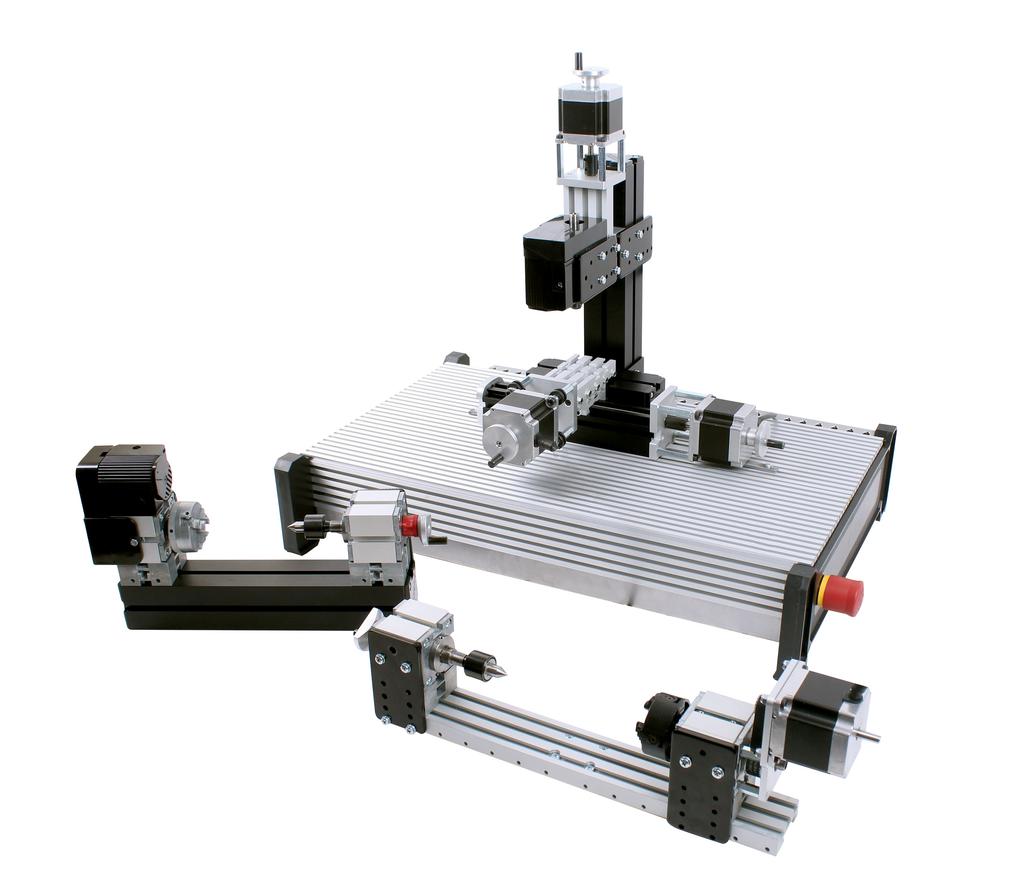
4 Before You Start Matrix Micro CNC Kits & Machines Modules These instructions provide a step by step guide to assembling the Micro CNC Machines from prebuilt Modules, Micro CNC System Controller, and Accessory Packs. Please Note: Matrix Supply four different Micro CNC Machine Kits, these are shown below. Each Kit is made from a number of specific Modules & Accessories. Please refer to the Assembly Instructions for your Kit as different kits do not include all the items listed below. The four Micro CNC Machine are: 2 axis Micro CNC Lathe (CN2668) 3 axis Micro CNC Milling Machine (CN4234) 4 axis Micro CNC Milling Machine (CN8285) Complete Micro CNC set (CN3885) The 4 Micro CNC Machines are assembled from different combinations of the following modules: Lathe Module Vertical Mill Module Cross Slide Module 4-Axis Extended Bed Module The Micro CNC Machines are assembled onto the Micro CNC System Controller and Base Plate (CN4079) shown below: 4


5 Assembly Notes: Matrix Micro CNC Kits & Machines Modules The Micro CNC System Controller and Base Plate comes pre-fitted with a large retaining bar and two small retaining bars as shown below. These are pre-positioned to attach the machine module conveniently towards the rear of the platform. These can be repositioned anywhere on the platform by loosening the screws slightly and sliding the retaining bars form the ends of the platform and repositioning as required. Small retaining rods Large retaining rod Inserting Connection Pieces into Module T-slots To attach the Lathe module to the Cross Slide module you will need to inset a Connection Piece, from the accessory pack, into the T-slots in the module bases. Note: the Connection Piece is Keyed as shown opposite. When inserting a Connection Piece it is important to ensure the Key is in the right orientation. Key Use the Allen Key screw driver, shown below, to tighten / slacken connection pieces. When the Key is positioned into a T-slot the Connection Piece can only be inserted upto the end of the module. 5 When the Key is positioned to the outside the T-slot the Connection Piece can be positioned anywhere along the module.

6 2 axis Micro CNC Lathe (CN2668) Assembly Parts required: Micro CNC System Controller and Base Plate (CN4079) Cross Slide Module Lathe Module Accessory Pack (Lathe) Step 1 Attach Cross Slide Module to Base Plate Remove one of the screws from the long retaining bar attached to the platform, loosen the other screw to allow the long retaining bar to be lifted. Loosen Remove Slide the Cross Slide module onto the long retaining bar. Position the Cross Slide module centrally on the platform. Tighten both screws to hold the Cross Slide module securely in place. Tighten 6


7 Step 2 Attach Lathe Module to Base Plate Place Lathe module behind the Cross Slide Module at the rear of the platform and position it so that you can insert a connection piece into the T-slots. The Connection Piece should be fully inserted into the Cross Slide module with the Key as shown opposite. Connection piece Cross slide module Allen Key Screwdriver Lathe module Holding the Connection Piece in place with the Allan Key Driver carefully slide the Lathe module along the Cross Slide module until the Tailstock is aligned with the edge of Cross Slide module stepper motor as shown opposite. Align Tailstock with Stepper Motor Insert a second Connection Piece into the T-slots at the other end of the Cross Slide and Lathe modules; again ensure the Key of the Connection Piece is inserted into the T-slot of the Cross Slide module. Tighten both Connection Pieces. Insert the small retaining bars into either side of the Lathe module and tighten screws Cross slide module Lathe module Small retaining bars Step 3 Attach Live Centre & Tool Post Insert the Live Centre, found in the accessory pack, into the Tail Stock of the Lathe Module. Assemble the Tool post using the M4x70 socket head screw and a slot nut from the accessory pack. 7


8 Slide the assembled tool post into an appropriate slot in the bed of the Cross Slide module and tighten the central screw. Assembled Micro CNC Lathe & Controller Base Plate Step 4 Lathe Pre-use Adjustments Before you can use the lathe the cutting tool will need to be centred to the rotational axis of the work piece. This is achieved by placing a centring bit into the head stock of the lathe using the 3.5 mm collet (this does not have grooves at the end) and aligning the cutting tool with the bit. Remove the 3 Jaw Chuck by placing the small bar in the hole at the rear of the motor, hold this tightly and turn the chuck anticlockwise to remove. Place the centring bit and a 3.5mm collet into the headstock and secure with the collet holder as shown opposite. 8
 to adjust the height of the bit.")


9 Loosen the screws in the tool holder and place in the cutting bit, use the small brass shims (1mm, 0.4mm, and 0.1mm) to adjust the height of the bit. The bit needs to be in line with the centring bit. Secure the cutting tool into the tool holder by tightening the tool post screws. The Chuck can be tightened and slackened using the two small rods. Locate a rod in the holes and move anticlockwise to loosen and clockwise to tighten the jaws onto a work piece. Depending on the size of the work piece you wish to turn you may need to adjust the spacing between the tailstock and the headstock. This can be achieved by loosening the Connection Piece between the lathe bed and the tailstock, and the Stabilising Plate screws. The tailstock is then free to slide towards or away from the headstock. Once in postion retighten the Connection Piece and the Stabilising Plate screws. Any final adjustment can be made by roting the Jog wheel of the tailstock to secure the workpiece. Tailstock free to move 9
 Step 1 Attach Cross Slide Module to Base Plate Loosen Remove one of the screws from the long retaining bar")

10 3 axis Micro CNC Milling Machine (CN4234) Assembly Parts required: 3 axis Micro CNC Milling Machine (CN4234) Assembly Cross Slide Module Vertical Mill Module Accessory Pack (Mill) Step 1 Attach Cross Slide Module to Base Plate Loosen Remove one of the screws from the long retaining bar attached to the platform, loosen the other screw to allow the long retaining bar to be lifted. Remove Slide the Cross Slide module onto the long retaining bar. Position the Cross Slide module centrally on the platform. Tighten both screws to hold the Cross Slide module securely in place. Tighten 10
11 Step 2 Assemble the Vertical Mill Module The Vertical Mill module is packed in two parts and requires assembling prior to attaching to the Base Plate. Three parts are required for the assembly: 1. Tool Post & Motor Assembly 2. Short Machine Bed 3. Clamping Plate Tool Post & Motor Assembly Short Machine Bed Clamping Plate Clamping Plate as Shipped Place the Clamping Plate into the screw slots of the Short Machine Bed as shown opposite. Slide the Tool Post & Motor Assembly onto the Short machine bed ensuring the three clamping plates locate into the T-slots of the Tool Post. The Short Machine Bed should be positioned underneath the Motor. Carefully place the assembly onto a flat surface. First tighten the two screws located on the inner face of the Short Machine Bed, you will need to insert the screwdriver into the short machine bed as shown opposite. Next tighten the four screws located on either side of the Tool Post. 11
12 Step 3 Attach Vertical Mill Module to Base Plate Place the Vertical Mill module behind the Cross Slide Module at the rear of the platform and position it centrally along the carriage Vertical mill module Centre between carriage Cross slide module Using the Allen Key Screwdriver, insert a connection pieces into the T-slots between the Vertical Mill module and the Cross Slide module, (stepper motor end shown opposite). The Connection Piece should be fully inserted into the Cross Slide module with the Key going into the Vertical Mill Module, see page 3 for Key insertion details. Vertical mill module Allen Key Screwdriver Insert connection pieces into the T-slots between the Vertical Mill module and the Cross Slide module. The Connection Piece should be fully inserted into the Cross Slide module with the Key as shown opposite. Tighten the Connection Pieces. Insert the small retaining bars into either side of the Lathe module and tighten screws Small retaining bars 12

")

13 Step 4 Attach the Vice Assemble the Vice by loosely attaching 4 Slot nuts to the vice using four M4x6 screws, screws and slot nut are included in the accessory pack Slide the assembled Vice into the slots in the bed of the Cross Slide module and tighten the central screw. Step 5 Attach Cutting Bit To attach a cutting bit to the Motor Assembly use the 1/8th Inch collet (this has groves on the end) Place the collet into the motor assembly and secur in place using the collet holder; do not tighten Insert the cutting bit into the collet and tighten the collet holder until the cutting bit is held in place To secure the cutting bit into the motor assembly use the small bar to hold the motor shaft steady while the collet holder is tightend with the spanner. 13
.")
14 Assembled 3 axis Micro CNC Milling Machine & Controller Base Plate Step 6 3 Axis Vertical Mill Pre-Use Adjustments Before using the 3 axis Micro CNC Milling Machine it may be necessary to adjust the height of the cutting tool this can be achieved manually or by using the control software (software use is covered in the free curriculum). To manually adjust the cutting tool height two methods are employed depending on whether large or small adjustments are required. For small adjustment the cutting tool can be repositioned by turning the jog handle attached to the Z axis stepper motor. For large adjustment it will be necessary to move the cutting tool up or down as follows. Loosen, but do not remove, the four screws located on either side of the tool post. Loosen screws 14
15 Loosen, but do not remove the Locknut Screw Hold the Cutting Tool Head securely while loosening the Connection Piece located between the Tool Post and the Small Cross Slide/Motor Assembly. Move the Cutting Tool Head up or down as required and then tighten all fixings. 15
 Module Step 1 Attach Cross Slide Module to Base Plate Remove one of the screws from the long retaining")

16 4 axis Micro CNC Milling Machine (CN8285) Assembly Parts required: 3 axis Micro CNC Milling Machine (CN4234) Assembly Cross Slide Module Vertical Mill Module 4-Axis Extended Bed Accessory Pack (Mill) Module Step 1 Attach Cross Slide Module to Base Plate Remove one of the screws from the long retaining bar attached to the platform, loosen the other screw to allow the long retaining bar to be lifted. Loosen Remove Slide the Cross Slide module onto the long retaining bar. Position the Cross Slide module centrally on the platform. Tighten both screws to hold the Cross Slide module securely in place. Tighten 16


17 Step 2 Assemble the Vertical Mill Module The Vertical Mill module is packed in two parts and requires assembling prior to attaching to the Base Plate. Three parts are required for the assembly: 1. Tool Post & Motor Assembly 2. Short Machine Bed 3. Clamping Plate Tool Post & Motor Assembly Short Machine Bed Clamping Plate Clamping Plate as Shipped Place the Clamping Plate into the screw slots of the Short Machine Bed as shown opposite. Slide the Tool Post & Motor Assembly onto the Short machine bed ensuring the three clamping plates locate into the T-slots of the Tool Post. The Short Machine Bed Should be positioned underneath the Motor. Carefully place the assembly onto a flat surface. First tighten the two screws located on the inner face of the Short Machine Bed, you will need to insert the screwdriver into the short machine bed as shown opposite. Next tighten the four screws located on either side of the Tool Post. 17


18 Step 3 Attach Vertical Mill Module to Base Plate Place the Vertical Mill module behind the Cross Slide Module at the rear of the platform and position it centrally along the carriage Vertical mill module Centre between carriage Cross slide module Using the Allen Key Screwdriver, insert a connection pieces into the T-slots between the Vertical Mill module and the Cross Slide module, (stepper motor end shown opposite). The Connection Piece should be fully inserted into the Cross Slide module with the Key going into the Vertical Mill Module, see page 3 for Key insertion details. Vertical mill module Allen Key Screwdriver Insert connection pieces into the T-slots between the Vertical Mill module and the Cross Slide module. The Connection Piece should be fully inserted into the Cross Slide module with the Key as shown opposite. Tighten the Connection Pieces. Insert the small retaining bars into either side of the Lathe module and tighten screws Small retaining bars 18
19 Step 4 Reposition the Cutting Tool Head Before attaching the 4-Axis Extended Bed Module you will need to reposition the Cutting Tool Head at the top of the Tool Post as follows: Loosen, but do not remove, the four screws located on either side of the tool post. Loosen screws Loosen, but do not remove the Locknut Screw Hold the Cutting Tool Head securely while loosening the Connection Piece located between the Tool Post and the Small Cross Slide/Motor Assembly. Move the Cutting Tool Head up or down as required and then tighten all fixings. 19


20 Step 5 Attach the 4-Axis Extended Bed Module Move the Y-axis cross slide away from the tool post by turning the jog handle anticlockwise to allow sufficient room to insert the Extended Bed module. The 4 Axis Extended Bed module is packed as shown opposite. Prior to assembly you will need to reposition the motor and tailstock. Remove the four Stabilising Plate screws. Remove screws Loosen the Connection Piece located between the bed and motor assembly. Slide the motor assembly towards the end of the bed and align the holes of the stabilising plate with the holes in the bed. Replace the Stabilising Plate screws and retighten the Connection Piece. 20


 Place the collet")


21 Loosen the Connection Piece located between the bed and tailstock. Slide the motor assembly towards the end of the and align the holes of the stabilising plate with the holes in the bed. Replace the Stabilising Plate screws and retighten the Connection Piece. Slide the 4 Axis Extended Bed module into the slots in the bed of the Cross Slide module and tighten the four retaining screws. Step 6 Attach Cutting Bit To attach a cutting bit to the Motor Assembly use the 1/8th Inch collet (this has grooves on the end) Place the collet into the motor assembly and secur in place using the collet holder; do not tighten Insert the cutting bit into the collet and tighten the collet holder until the cutting bit is held in place To secure the cutting bit into the motor assembly use the small bar to hold the motor shaft steady while the collet holder is tightend with the spanner 21
22 Assembled 4 axis Micro CNC Milling Machine & Controller Base Plate Step 7 4 Axis Vertical Mill Pre-use Adjustments Before using the 4 axis Micro CNC Milling Machine it may be necessary to adjust the height of the cutting tool to enable sufficient movement of the cutting tool; it may also be necessary to adjust the length of the extended bed to ensure a work piece is held securely. Adjusting the Cutting Tool Head Position To manually adjust the cutting tool height two methods are employed depending on whether large or small adjustments are required. For small adjustment the cutting tool can be repositioned by turning the jog handle attached to the Z axis stepper motor. For large adjustment it will be necessary to move the cutting tool up or down as follows. 22


23 Loosen, but do not remove, the four screws located on either side of the tool post. Loosen screws Loosen, but do not remove the Locknut Screw Hold the Cutting Tool Head securely while loosening the Connection Piece located between the Tool Post and the Small Cross Slide/Motor Assembly. Move the Cutting Tool Head up or down as required and then tighten all fixings. Adjusting the Length of the Extended Bed Both the motor and the tailstock can be adjusted to allow workpieces of different sizes to be secured. To reposition the motor and tailstock. remove the four Stabilising Plate screws. And loosen the Connection Pieces between the bed and motor, or tailstock as required. Reposition to a suitable location and replace the screws then tighten the Connection Pieces. 23 Remove screws


24 Adjusting the Length of the Extended Bed Both the motor and the tailstock can be adjusted to allow workpieces of different sizes to be secured. To reposition the motor and tailstock remove the four Stabilising Plate screws and loosen the Connection Pieces between the bed and motor, or tailstock as required. Reposition to a suitable location and replace the screws then tighten the Connection Pieces. Remove screws To secure a workpiece into the 4 Jaw Chuck use the 2mm Allen key to adjust the position of each Jaw individually, there are guide lines on the face of the chuck to help centralise the workpiece. A live centre can be fitted to the tailstock to secure longer workpieces as required. 24
 shown below: The Controller Base Plate has a Linux based control system at its core, and houses all electrical connections")
25 Matrix MicroCNC Getting Started Introduction The Matrix Micro CNC Systems offer a range of three machines, Lathe, 3-Axis Milling Machine, and 4-Axis Milling Machine. Each of the machines is operated from the Controller and Base Plate (CN4079) shown below: The Controller Base Plate has a Linux based control system at its core, and houses all electrical connections required to connect to the three machines, and for connection to a PC. The Controller Base Plate also incorporates a range of safety features, both software enabled and physical to ensure safe operation within an educational setting. This section of the document provides information on how to safely use the hardware and software; it also demonstrates how to import your Numerical Control (G-Code) files to the controller and how to set up, and operate, your machines using the control software provided. Hardware Overview Controller Base Plate Platform Inlet Face The controller base plate provides a secure platform for each of the three machines in the range and the previous sections cover installation of these to the platform. Once a machine is securely mounted electrical connections are made to the Platform Inlet Face; the connection for the stepper motors are dependent on the type of machine being used and are covered in the next section. 25

26 The DC motor connection is used to operate the Headstock (Chuck) of the lathe, or the Cutting bit for the milling machines. The motor is turned on using the DC motor On/Off switch at the right hand end of the inlet face; positioned to allow easy access while the machines are running. The DC motor CANNOT be operated unless the platform is connected to a PC and the control software is running. In addition, the DC motor is also connected to the Emergency Stop button located on the opposite end of the platform, right front during normal operation. In the event of the emergency stop button being pressed the restart procedure should be followed, see Page XX. The USB connection provides an interface to the PC. The USB is used to internally power the embedded Linux controller allowing program files to be imported, and machine setting to be entered without the motors being energised. The IEC Power Inlet provides a switched, and fused, connection to a V (50-60Hz) mains supply. In addition, it is RECOMMENDED that the mains connection is provided through an RCD (Not Supplied). If manual adjustments to the stepper motors need to be made, i.e. during tooling, or origin, setup, the IEC switch can be turned Off, this will remove power from the motors to allow the adjustments to be made. Turning off the power with this switch has no effect on the software, or any programs running, see warning notes at the end of the document. Note the stepper motors should not be moved manually while energised. Platform Emergency Stop Face Matrix MicroCNC machines provide two methods of initiating and emergency stop. These are a Physical emergency stop button located on the right hand end of the Controller Base Plate and a Software emergency stop within the control software. The software emergency stop will be covered later in this document. To disengage the Emergency Stop, twist the Red cap clock wise. The physical Emergency Stop is activated by Hitting/Pressing into the platform, once engaged it will terminate power to the stepper motors and the DC motor simultaneously. After pressing the Emergency Stop button it is recommended that you follow the restart procedure stated below. Caution Disengaging the Emergency Stop Will IMMEDIATELY Restore Power to Both Stepper and DC Motors. If a cutting program is running it will need to be stopped. Cutting operations MUST BE STOPPED before power is restored. 26


27 The restart procedure below assumes that the Physical emergency stop button was activated to prevent injury to person(s) or to prevent damage to the machine/tool/part. Restart Procedure 1. Isolate Controller Base Plate from mains electrical supply 2. Switch off the DC Motor Toggle Switch. 3. Switch off the IEC Power Switch. 4. Stop the cutting program in software. (Note: the Physical emergency stop has no effect on the cutting tool program, this will continue running until stopped in software. 5. Manually operate stepper motor jog wheels to move cutting tools clear of the work piece/machinery. 6. Remove and replace any damaged cutting tools / stock from the machine. 7. Disengage the Physical emergency stop button After following the above procedure cutting operations can be resumed after ensuring the Hazardous condition that initiated the emergency stop has been removed. Machine Electrical Connections 2-Axis Lathe (CN2668) Connect the Cross Slide Module Motor Leads to the X and Z sockets on the platform, connect the DC Motor Jack Plug to the DC Motor socket on the platform as shown below. DC motor Z-axis motor X-axis motor Cross slide module Lathe module 27 Connections

28 3-Axis Milling Machine CN4234 Connect the Cross Slide Module Motor Leads to the X and Y sockets on the platform Z-axis motor X-axis motor Cross slide module Connect the Mill Module Z-Axis Motor Leads to the Z socket on the platform, connect the DC Motor Jack Plug to the DC Motor socket on the platform as shown below. Z-axis motor DC motor Mill module Connections 28


29 4-Axis Milling Machine CN8285 Connect the Cross Slide Module Motor Leads to the X and Y sockets on the platform Z-axis motor X-axis motor Cross slide module Connect the Mill Module Z-Axis Motor Leads to the Z socket on the platform, connect the DC Motor Jack Plug to the DC Motor socket on the platform as shown over the page below. Z-axis motor DC motor Mill module Connect the A-Axis of the Extended Bed Module to the A Socket on the platform as shown over the page. A-axis motor A-axis (4 th rotary) Connections 29

30 Matrix MicroCNC Control Software Connecting to a PC Connect a PC to the Controller Base Plate via the USB connection port; after a few seconds the MATRIXCNC Windows Directory shoud open as shown below. You do not need to power the Controller Base Plate as the controller hardware is internally powered from the PC. NOTE: If you receive a warning about Potential Security Risks, as shown below press y to update the cached key. You may need to disconnect and then reconnect the PC/Laptop after the update. MATRIXCNC Windows Directory Security Warning Select y and continue Installing Drivers If using the software on a computer for the first time it is advisable to install the drivers prior to launcing the control programs. Use the following instruction to install the drivers: Connect Platform to PC, wait a few seconds for the MATRIXCNC Drive to open. Select and open the Windows folder 30


31 Select and open the Drivers folder Select and open either microcnc_32bit_installer. exe or microcnc_64bit_installer.exe depending on your computers operating system. In the User Account Window select Yes when asked Do you want to allow this app to make changes to your device? In the Installer Window, shown opposite, select Next > When the driver begins to install a Windows Security window may launch; select Install to continue the installation 31
, these are used to operate the three different machine types, and to facilitate file transfers from a Windows based system to the controller software; the table below describes the function of")
32 Once the insallation completed, click the Finish button to return to the MATRXCNC Drive. Batch Files Within the MATRIXCNC directory you have access to four batch files (.bat), these are used to operate the three different machine types, and to facilitate file transfers from a Windows based system to the controller software; the table below describes the function of each batch file: Batch files Function Use with... Launch_2AXIS_LATHE.bat Launch_3AXIS_MILL.bat Launch_4AXIS_MILL.bat Launch_File_Transfer.bat Sets up control software for Turning operations. Cross Slide Module has X-Axis and Z-Axis Sets up control software for 3-Axis Milling operations. Cross Slide Module has X-Axis and Y-Axis, Vertical Mill Module has Z-axis Sets up control software for 4-Axis Milling operations. Cross Slide Module has X-Axis and Y-Axis, Vertical Mill Module has Z-axis Extended Bed Module Has A-Axis (rotary) Used to import and export Numerical Control (G-Code) between Windows and Linux Directories. Lathe Kit - CN2668 Complete Set CN3885 (Lathe Config.) 3-Axis Milling Machine Kit CN4234 Complete Set CN3885 (3-Axis Mill Config.) 4-Axis Milling Machine Kit CN8285 Complete Set CN3885 (4-Axis Mill Config.) All kits in conjunction with control software The batch file selected will depend on the type of machine attached to the platform, or whether a file need to be transferred between systems. File transfer will be covered in a separate section. 32

 Note: The first time you open a file you may be asked to Store")
 type y and press enter After a few seconds, a Splash screens")

33 Opening a Control Program After selecting and opening an appropriate batch file you will see a window similar to the one opposite. (this example shows the Launch_4AXIS_MILL.bat ) Note: The first time you open a file you may be asked to Store key in cache? (y/n) type y and press enter After a few seconds, a Splash screens will open and the MicroCNC control software should launch, after a few more seconds the control program will launch and a window similar to the one below will open, (this example shows the 4-Axis Milling configuration): Splash screens: 33

34 Control Software Overview The programs for the three different machines are essentially the same; however, the available axis, and the preview screen will be different dependent on the program that was opened. The example below shows the 4-Axis Machine program. Machine Power ON/ OFF Toggle button Run, Pause, & Stop Software Emergency Stop ON/OFF Toggle button Axis Select Radio Buttons Stepper Motor Control Buttons Home Axis Button Preview Screen Information Screen 34 Software Emergency Stop ON/OFF Toggle button Turns off power to all stepper motors and the DC motor, also turns off the machine power and terminates the cutting program being executed. After activation of the Software Emergency Stop the DC Motor switch on the Controller Base Plate should also be turned off and the cutting tool moved clear of the work piece. Machine Power ON/OFF Toggle button Turns on power to the stepper motors only. The DC Motor is turned on and off using the switch on the Controller Base Plate. Run, Pause, & Stop Buttons Run Starts the cutting program from the beginning of the NC program file. Pause Pauses the cutting program when pressed; to resume the cutting program press the Pause button again. Stop Ends the cutting program. Axis Select Radio Buttons Used to select an axis for manual control Disabled while a NC program is running Stepper Motor Control Buttons Used in conjunction with the Axis Select radio buttons to move the position of the selected axis; the + and - direction of movement depends on the type of machine being used. Movement can be continuous, or in incremental steps, depending on the selected setting in the drop down menu next to the + and - button. Home Axis Button Used to set the Home position of the cutting tool relative to the axis coordinate system being used. The zero point or Home will depend on the machine type, cutting program, part, and stock settings used. Preview Screen Provides information on the cutting tool position, and gives a preview of the part, stock and cutting tool path, the view can be moved about the preview screen and the orientation changed using the view selection buttons above the preview screen. Information Screen Provides details of the G-code file loaded and displays relevant messages during operation and setup.


35 Basic Operations Operate Motors When a control program is launched its default state is to have the software Emergency Stop engaged, and the Machine Power turned off; in this state the axes selection and motor control buttons are greyed out and are not selectable, as shown opposite. To operate the stepper motors, disengage the software Emergency Stop, then turn on the Machine Power ; the axes selection radio buttons and the stepper motor controls will then be enabled. To manually operate the stepper motors, select the axis to be moved using the radio buttons and use the + or - buttons to move the carriage along the selected axis; note the direction of movement will depend on which machine program is being used, see following sections. You can control the stepper motors with continuous movement, or stepped increments, by changing the selection in the box next to the + and - buttons, as shown opposite. With Continuous selected the motors will move continuously while the + or - buttons are being pressed. With one of the increment steps selected (0.1000, , , or ) the motor will move incrementally by the selected distance for each press of a + or - button. To operate the DC Motor the platform needs to be connected to a computer and the appropriate control program open; if the software is not open the DC Motor cannot be activated. Unlike the stepper motors the DC motor is not controlled through the program but via the toggle switch on the control face of the platform; the motor should be running with the switch in the upper position, and off when the switch is in the lower position. 35


36 Lathe Functions Step 4 of the 2 axis Micro CNC Lathe (CN2668) Assembly instructions give details of how to physically set the centre zero for the lathe cutting bit. In addition, this point may need to be set as the zero or Home position in the control software. The following instructions provide information on how to set the control software Home position after aligning the cutting tool with the centring bit. Note: alignment of the tool with the centring bit can be done by manual adjustment of the lathe with the Controller Base Plate power turned off, or using the control software to move the lathe, Controller Base Plate power would need to be on. Select the axis to be moved using the Axis Radio Buttons and set the movement to continuous, or one of the incremental steps (0.1 to ), use the + and - buttons to move the axis to the required position. Refer to diagrams below for relevant direction of movement. Use continuous for large movements, then fine tune the position with incremental steps (or manually). Once the Cutting tool is in the correct zero or home position click the Home Axis button the coordinates in the preview area will be set to zero (0.000) with the symbol displayed next to the homed axis. Un-Homed Coordinates Homed Coordinates Lathe Axis Movement Direction The image opposite shows the direction of movement for the Lathe Axes corresponding to the + and - Stepper Motor Control buttons. NOTE: to avoid Crashing the carriage into the end of the machine bed change the movement setting from continuous to one of the incremental settings such as as the Zero position is approached. 36

37 Milling Machine Setup Functions Step 5 of the 3 axis Micro CNC Milling Machine (CN4234) Assembly instructions (also Step 6 of the 4 axis Micro CNC Milling Machine (CN4234) Assembly Instruction) give details of how to physically set the home or zero position of the mill cutting bit. In addition, this position may need to be set as the zero or Home position in the control software. The following instructions provide information on how to set the control software Home position after aligning the cutting tool with Home or Zero of the workpiece. Select the axis to be moved using the Axis Radio Buttons and set the movement to continuous, or one of the incremental steps (0.1 to ), use the + and - buttons to move the axis to the required position. Refer to diagrams below for relevant direction of movement. Note: alignment of the cutting bit with the home or zero of the workpiece can be done by manual adjustment of the mill axes with the Controller Base Plate power turned off, or using the control software to move the mill axes, Controller Base Plate power would need to be on. 3-axis mill Use continuous for large movements, then fine tune the position with incremental steps (or manually). Once the Cutting Bit is in the correct zero or home position click the Home Axis button for each axis X, Y, & Z for the 3-Axis Mill, (X, Y, Z, & A for the 4_axis Mill), the coordinates in the preview area will be set to zero (0.000) with the symbol displayed next to the homed axis. NOTE: to avoid Crashing the carriage into the end of the machine bed change the movement setting from continuous to one of the incremental settings such as as the Zero position is approached 4-axis mill Un-Homed Coordinates Homed Coordinates 37
on the 4-Axis Machine A-axis File Transfers In the MATRIXCNC")
, your G-Code files, between a Windows based PC and the Linux system within the Controller Base Plate. To Launch the file transfer program, select and open the Launch_File_Transfer.")
38 Milling Machines Axis Movement Directions The images below shows the direction of movement for the Milling Machine Axes corresponding to the + and - Stepper Motor Control buttons. The X, Y, & Z Axes are the same for both the 3-Axis and 4-Axis machines, with the addition of a 4th Rotary axis (A-Axis )on the 4-Axis Machine A-axis File Transfers In the MATRIXCNC Windows Directory there is a Batch file (Launch_File_Transfer.bat), this is used to facilitate the transfer of Numerical Control files (*.nc or *.ngc), your G-Code files, between a Windows based PC and the Linux system within the Controller Base Plate. To Launch the file transfer program, select and open the Launch_File_Transfer.bat batch file and open as shown opposite: 38


39 After a few second the WinSCP Login window will open. Click the Login button, after a few seconds a window similar to the one below will open. Note: If a connection cannot be established, ensure the correct drivers have been installed, see Installing Drivers. Windows drive Linux directory Navigating the Windows and Linux Drives Drives can be selected from the drop down menu; for example, to select a USB drive click on the down arrow and select the required drive, as shown opposite: After selecting a drive navigate through folders by double left clicking to open folders and using the button to navigate back up to through the Parent Directories to the Root Directory. 39


40 Alternatively, Right Click the drive ribbon and select Open Directory/Bookmark, or double Left Click the drive ribbon, to open a standard Windows directory navigation window, as shown opposite: Directory ribbon Right click Left click The simplest way to transfer files is to drag & drop them from one directory/folder to another; this automatically creates a copy of the file in the new location. The example below shows how to copy a file located on the PC desktop to the default file location on the Linux drive Left click and hold the file to be copied, then drag and drop the file in the new location. Left click & Hold Drag to Linux drive A copy of the file is now located in the default folder /home/machinekit/nc_files of the Linux Drive. The file can now be opened by the machine control software as shown opposite: 40

 The images opposite show the 2D sketch, and 3D Model, of a part to be turned on the MicroCNC Lathe.")


41 Example Project This example project will show how to create a simple part on the Matrix MicroCNC Lathe. The part was first designed using a typical CAD package, Solidworks in this case, and then converted to a.dxf file. A typical CAM package, CAMBAM in this case, was then used to generate the G-Code used by the Matrix MicroCNC Lathe. CAD Design to Dxf File (Solidworks Example) The images opposite show the 2D sketch, and 3D Model, of a part to be turned on the MicroCNC Lathe. First save the sketch file as a.dxf file; this type of file can be imported into most CAM software packages, and will enable G-Code to be generated automatically from the drawing. Open your sketch file and then select File Save As. In the Save As window make sure you save the file type as Dxf (*.dxf). Usually you can use the default settings for the Dxf file, however you may need to select which features are used to save the file. For this part in Solidwork the default settings can be used; click OK to continue. Most CAD packages will then give the option to remove any parts of the sketch that have been included but are not required. In this example the centre line and the two end faces are not needed so could be removed here by selecting them and clicking the Remove Entities button then saving the file. However, for this example these will be removed in the CAM software. 41


42 Generate G-Code using CAM Software (CAMBAM Example) This project example is using the Example Part -Lathe 001.dxf file generated in Solidworks, and described previously; most CAD and CAM software packages can work with Dxf files. Import and Edit a Dxf File Open a Dxf file in the CAM package you are using. The sketch is imported as a single layer containing several lines. This imported sketch will need editing before the G-Code can be produced. In this example the image that has been imported needs to be edited to change the orientation so the sketch is in the +X and -Y orientation. It will also need to have three of the lines removed otherwise the CAM software will try to create a cutting path for the two ends and the centre line. Select the sketch by Left Clicking and dragging a box around the shape as shown opposite, all the lines will be selected as shown: Select Edit, Transform, Mirror from the menu. Select two points on the X Axis (mirror line), a mirror image of the original sketch is created in the correct orientation required to produce G-Code for a turning (Lathe) operation. 42


43 The sketch needs further editing to remove the Original sketch, the two end faces of the new sketch, and the centre line. Again, select all the lines in the original sketch by Left Clicking and dragging a box around the lines; any lines not fully inside the selection box will not be included. The two end faces are then selected by holding the Ctrl key and Left Clicking each line individually. There should be 11 lines highlighted and 5 lines unselected as shown opposite. The selected lines can be deleted using the Delete key, CTRL+X, keys, or by selecting Edit -> Cut. The remaining lines now need to be Joined to create a continuous polyline. Select the lines as before and then Join them by selecting Edit -> Join enter a tolerance of A single polyline will be created as shown opposite: Input Machining Parameters Parameters need to be entered for the stock size, offset and surface, type of Post Processor*, and tool profile* *(Depends on machining operation to be performed). In this example these values are set as shown opposite. The stock used is a machining wax cylinder with dimensions 70mm X Ø28mm. The Stock Size entered is X =70, Y = 28, Z = 28. The Y off value of -14 and the Stock Surface value of 14 centres the stock along the central axis of the part to be machined, as show below (the piece of stock is represented by the orange box). 43


44 Define Cutting Path After entering the Machining parameters the next stage is to define the cutting path. However, before this can be done it may be necessary to make adjustments to the position of the stock in the machine, or the position of the part within the stock. In the screen shot below the example part is to be machined from a piece of stock slightly larger than the part (part length = 60mm, stock length = 70mm). The reason for this is that the stock has to be held in the lathe by the chuck; and the chuck s jaws extend 9.4mm from the chuck face. It can be seen from the image below that the cutting path falls inside the area used by the chuck jaws to hold the stock, if the example part is machined as is the cutting tool would damage the chuck or vice versa. Space required by chuck jaws In this example the cutting path needs to be moved clear of the chuck jaws Select the polyline as before, then select Edit -> Transform -> Move from the menu. Pick a point on the line and move to the opposite end of the stock as shown, take care not to move the polyline up or down. Select the line as before then from the menu select Machining -> Lathe This will create Part1 and Lathe1 operation under the under the machining parameters as shown: Select the Lathe1 operation then check and set the following parameters Check the Primitive IDs match the Polyline of your part, in this example it is 17, there should be no other lines included. 44


45 Note: the following settings are for the Example Part Lathe 001 Only. Clearance Plane set to 15mm, this ensures the cutting tool is moved clear of the stock as it finishes one cut and moves to the next. Depth Increment set to 0.4mm, this is how deep the cutting tool will cut into the stock material at each pass. Stock Surface set to 14mm, this is the radius of our stock. Cut Feedrate set to 500, this sets the speed of travel of the cutting tool along the workpiece, larger values move the tool quicker. Harder materials need to be cut at slower speeds. Plunge Feedrate set to 150, this is the speed that the cutting tool is fed into the material, again harder materials require a slower speed. Work Plane select XZ from the drop down menu, this sets the axis for the lathe operation as shown previously the X-Axis cuts into the material towards the axis of rotation, the Z-Axis cuts along the length of the part. Lathe Cut Direction select Right Hand from the drop down menu, a right hand tool cuts from right to left, in this example we are cutting the stock from the end towards the chuck. Roughing / Finishing - select Roughing from the drop down menu, a roughing operation will roughly cut the stock to size, slightly larger than the finished dimensions. It is possible to include additional cutting operation one after the other; for example, a finishing operation could follow a roughing operation, parameters would need to be set independently for each operation. Tool Profile - select Lathe from the drop down menu. Generate Toolpaths After parameters have been set for the Machining and Lathe1 operation a tool path can be generated. Select Machining -> Generate toolpath form the menu. The blue lines show individual cutting paths and the yellow arrows indicate the cutting direction. The two images below show how the number of cutting paths reduces as the depth increment is increased: 45 Depth Increment = 0.25mm Depth Increment = 2mm


46 Produce G-Code After checking the toolpaths are correct G-Code can be produced. Select Machining -> Produce gcode from the menu and save the file to a suitable location. The G-Code can be checked by either selecting Machining -> Edit gcode from the menu or by opening in a text editor program such as Notepad Transfer G-Code File to Linux From the MATRIXCNC drive select and open the Launch_File_Transfer.bat program. Click Login to continue. Navigate through the Windows Drive to the location the CAMBAM generated G-Code file was saved. Left Click and Hold, then drag the file to the Linux drive on the left. A copy of the file will be created in the new location, as shown below. 46


. Select the file and click Open as shown below.")
47 Lathe Control Program After transferring the CAMBAM generated G-Code file to the Linux drive select and open the Launch_2AXIS_LATHE.bat batch file as described previously. This will open the Lathe control program. After the control program has launched open the Example Part Lathe 001.nc file by selecting File -> Open from the menu, in the Open window click on the File of type: drop down menu and select All Files(*). Select the file and click Open as shown below. The file will be opened with the G-Code available to view in the lower window, there will also be an image showing the cutting paths to be machined, as shown below. 47


48 Setup the Lathe Before inserting the stock into the lathe the cutting tool should be Homed as described earlier, see Lathe Assembly Step 4. Once the cutting tool has been aligned with the centring bit the X and Z axes need to be homed in the control program. Refer to the previous section for operational instruction for the control software. Select each axis in turn and click the Home Axis button. When an Axis has been homed it will have next to the value. Un-homed Once each axis has Homed or zeroed, move the cutting tool using clear of the stock. This should be done using the control program, not by manually turning the jog wheels. Set the movement to Homed Continuous and use the + button to move the cutting tool along the Z-axis approx. 70mm and the X-axis approx. 18mm, as shown below. Turn the Controller Base Plate power off using the Main IEC switch; this will not affect the homed settings of the lathe provided the axes are not moved. With the power off, place the stock into the lathe as shown below. Note the clearance between the cutting tool and the stock. 48


49 After setting up the stock the power can be restored to the Controller Base Plate. Ensure both the Physical and software emergency stop buttons are disengaged and apply power to the lathe as described below. Start the DC Motor using the switch on the side of the Controller Base Plate. To operate the stepper motors, disengage the software Emergency Stop, then turn on the Machine Power ; the axes selection radio buttons and the stepper motor controls will then be enabled. With the DC motor running and the stepper motors energised start the cutting program by clicking the Play Button as shown opposite. When the machining process has ended the cutting tool stop at Z = 10, X = 30; move the cutting tool using clear of the stock as previously. Turn off the power to the motors as before and remove the finished piece from the lathe. 49


50 Matrix Technology Solutions Ltd. The Factory 33 Gibbet Street Halifax, HX1 5BA, UK t: +44 (0) e:
Installing a 3 Indexer: Desktop Tools
 888-680-4466 ShopBotTools.com Installing a 3 Indexer: Desktop Tools built after October, 2012 Copyright 2016 ShopBot Tools, Inc. page 1 Copyright 2016 ShopBot Tools, Inc. page 2 Table of Contents Overview...5
Shapeoko XXL Assembly Guide
 Shapeoko XXL Assembly Guide 04/27/2016 XXL Packing LIst Item Qty Description Y-Carriage (left) 1 Y-Carriage (right) 1 X/Z Assembly 1 40 Rail 3 1 rail has mounting holes for controller Wasteboard Half 2
CNC Chucker Lathe P/N 6600, 6610, and 6620
 WEAR YOUR SAFETY GLASSES FORESIGHT IS BETTER THAN NO SIGHT READ INSTRUCTIONS BEFORE OPERATING PRODUCT DESCRIPTION 6600 CNC Chucker w/3c headstock, ball screws, high-torque stepper motors & PC w/4-axis
Vinyl Cutter Instruction Manual
 Vinyl Cutter Instruction Manual 1 Product Inventory Inventory Here is a list of items you will receive with your vinyl cutter: Product components (Fig.1-4): 1x Cutter head unit complete with motor, plastic
Trade of Toolmaking Module 2: Turning Unit 1: Machine Controls and Operations Phase 2
 Trade of Toolmaking Module 2: Turning Unit 1: Machine Controls and Operations Phase 2 Published by SOLAS 2014 Unit 1 1 Table of Contents Document Release History... 3 Unit Objective... 4 Introduction...
Legacy Woodworking Machinery a division of Phantom Engineering. The Legacy CNC. Assembly Manual
 Legacy Woodworking Machinery a division of Phantom Engineering The Legacy CNC Assembly Manual New Orientation of the Legacy Step one: Re-orientation of the machine Remove the X-axis screw and supports.
Installing the 3 Indexer: PRS Standard Tools
 888-680-4466 ShopBotTools.com Installing the 3 Indexer: PRS Standard Tools Copyright 2016 ShopBot Tools, Inc. page 1 Copyright 2016 ShopBot Tools, Inc. page 2 Table of Contents Route Cable into Box...5
VARIABLE SPEED WOOD LATHE. Model DB900 INSTRUCTION MANUAL
 VARIABLE SPEED WOOD LATHE Model DB900 INSTRUCTION MANUAL 1007 TABLE OF CONTENTS SECTION...PAGE Technical data.. 1 General safety rules....1-3 Specific safety rules for wood lathe.....3 Electrical information.4
1. ASSEMBLING THE PCB 2. FLASH THE ZIP LEDs 3. BUILDING THE WHEELS
 V1.0 :MOVE The Kitronik :MOVE mini for the BBC micro:bit provides an introduction to robotics. The :MOVE mini is a 2 wheeled robot, suitable for both remote control and autonomous operation. A range of
VARIABLE SPEED WOOD LATHE
 MODEL MC1100B VARIABLE SPEED WOOD LATHE INSTRUCTION MANUAL Please read and fully understand the instructions in this manual before operation. Keep this manual safe for future reference. Version: 2015.02.02
ROTARY TABLE OPERATION AND SERVICE MANUAL HORIZONTAL AND VERTICAL. Horizontal & Vertical. Rotary Table (HVRT) Tilting Rotary Table
 Tilting Rotary Table") Horizontal & Vertical Rotary Table (HVRT) OPERATION AND SERVICE MANUAL Tilting Rotary Table Horizontal & Vertical Rapid Indexer VERTICAL AND HORIZONTAL ROTARY TABLE This Horizontal & vertical table is
Horizontal & Vertical Rotary Table (HVRT) OPERATION AND SERVICE MANUAL Tilting Rotary Table Horizontal & Vertical Rapid Indexer VERTICAL AND HORIZONTAL ROTARY TABLE This Horizontal & vertical table is
Ladybird Project - Vacuum Mould
 - Vacuum Mould Prerequisite Mould drawn and saved as an STL file in SolidWorks Focus of the Lesson On completion of this exercise you will have: Opened an STL file Set Machining Constraints Set up Tools
Operations Manual for Machines Equipped with a Rotary Axis Supplement to the WinCNC Operations Manual. 6/1/2015 Laguna Tools
 Operations Manual for Machines Equipped with a Rotary Axis Supplement to the WinCNC Operations Manual 6/1/2015 Laguna Tools TABLE OF CONTENTS Overview... 3 Safety Warning... 3 Preliminary Checks... 4 Verify
MILL ONE. Assembly Manual. Manual Illustrated by Gontarz Design Studio
 MILL ONE Assembly Manual Manual Illustrated by Gontarz Design Studio Safety Warnings and Guidelines 1. Be sure to carefully follow provided machine assembly instructions before machine use to ensure operator
LinuxCNC Help for the Sherline Machine CNC System
 WEAR YOUR SAFETY GLASSES FORESIGHT IS BETTER THAN NO SIGHT READ INSTRUCTIONS BEFORE OPERATING LinuxCNC Help for the Sherline Machine CNC System LinuxCNC Help for Programming and Running 1. Here is a link
The new generation with system accessories. Made in Germany!
 1 The new generation with system accessories. Made in Germany! For face, longitudinal and taper turning, thread-cutting. For machining steel, brass, aluminium and plastic. Mounting flange for fastening
Automatic Tool Changer (ATC) for the prolight A Supplement to the prolight 1000 User s Guide
 for the prolight A Supplement to the prolight 1000 User s Guide") Automatic Tool Changer (ATC) for the prolight 1000 A Supplement to the prolight 1000 User s Guide 1 1995 Light Machines Corporation All rights reserved. The information contained in this supplement (34-7221-0000)
Automatic Tool Changer (ATC) for the prolight 1000 A Supplement to the prolight 1000 User s Guide 1 1995 Light Machines Corporation All rights reserved. The information contained in this supplement (34-7221-0000)
4th Axis OWNERS MANUAL
 4th Axis OWNERS MANUAL Copyright Next Wave Automation All Rights Reserved. Version 3.0 March 31, 2017 Updates of this manual are available at www.nextwaveautomation.com. *Information in this manual is
Standard. CNC Turning & Milling Machine Rev 1.0. OM5 Control Software Instruction Manual
 Standard CNC Turning & Milling Machine Rev 1.0 OM5 Control Software Instruction Manual Legacy Woodworking Machinery 435 W. 1000 N. Springville, UT 84663 Standard CNC Machine 2 Content Warranty and Repair
ABM International, Inc. Navigator Assembly Manual
 ABM International, Inc. 1 1.0: Parts List Tablet (Qty. 1) Tablet mount (Qty. 1) NOTE: Mount may appear and operate different then image below Control Box (Qty. 1) Motor Power Supply (Qty. 1) 2 X-axis motor
Woody s Workshop Tooling for Clock Making
 Using the Sherline Headstock Motor for Clock Wheel cutting. Background In order to cut clock wheels on a lathe it is necessary to have a method of indexing the lathe chuck to the correct number of teeth
Lathe. A Lathe. Photo by Curt Newton
 Lathe Photo by Curt Newton A Lathe Labeled Photograph Description Choosing a Cutting Tool Installing a Cutting Tool Positioning the Tool Feed, Speed, and Depth of Cut Turning Facing Parting Drilling Boring
TurncrafterPlus. Variable Speed Mini Wood Lathe. User s Manual #TCLPLUS PRODUCT NO.
 TurncrafterPlus Variable Speed Mini Wood Lathe PRODUCT NO. #TCLPLUS User s Manual SPECIFICATIONS OF TURNCRAFTER PLUS MINI LATHE Model number:..............................................#tclplus Motor:......................................0V
CNC Router Part 2 Training Tutorial
 CNC Router Part 2 Training Tutorial Prepared by Steve Pilon - Version 1.1 September 2017 A Index B - Intro A- Index B- Intro C- Objective D- Required Items E- Opening CamBam and Loading a DXF F- Preparing
Conversational CAM Manual
 Legacy Woodworking Machinery CNC Turning & Milling Machines Conversational CAM Manual Legacy Woodworking Machinery 435 W. 1000 N. Springville, UT 84663 2 Content Conversational CAM Conversational CAM overview...
The ShopBot Indexer. Contents
 ShopBot Indexer Page -1- The ShopBot Indexer The ShopBot Indexer is basically a lathe with an extra level of precision built in you can precisely control the rotation of the headstock and also link it
Turning and Lathe Basics
 Training Objectives After watching the video and reviewing this printed material, the viewer will gain knowledge and understanding of lathe principles and be able to identify the basic tools and techniques
MODEL SK61732 COMPRESSOR SERVICE KIT
 MODEL SK61732 COMPRESSOR SERVICE KIT For use on 607 and 617 Model Compressors with.32 Stroke WARNING: Unplug the compressor before beginning disassembly. CAUTION: Improper assembly or use of damaged parts
PULL-THRU USER S MANUAL
 PULL-THRU USER S MANUAL G14x Part # 310 120 177 G20 Part # 310 120 188 G20x Part # 310 120 186 G40x Part # 310 120 163 TABLE OF CONTENTS SECTION 1 PCB DESIGN AND MOUNTING SECTION 2 MOUNTING ADAPTER TO
Mill One V2 Assembly Manual
 Mill One V2 Assembly Manual Throughout this policy the words "we", "us" and "our", or Sienci Labs will be used to refer to Sienci Labs Inc. herein and Mill One or machine will refer to Sienci Labs Sienci
V4 Premium Kit. Prusa i3 Build Guide
 V4 Premium Kit Prusa i3 Build Guide Hi! Congratulations on your purchase of the DIYElectronics.co.za Prusa I3 kit, the best South African 3D Printer Kit! Hopefully this should serve as complete guide to
CNC Router Tutorial Jeremy Krause
 CNC Router Tutorial Jeremy Krause Jeremy.Krause@utsa.edu Usage prerequisites: Any user must have completed the machine shop portion of the Mechanical Engineering Manufacturing course (undergraduate, sophomore
CNC Turning Training CNC MILLING / ROUTING TRAINING GUIDE. Page 1
 CNC Turning Training www.denford.co.uk Page 1 Table of contents Introduction... 3 Start the VR Turning Software... 3 Configure the software for the machine... 4 Load your CNC file... 5 Configure the tooling...
The new generation with system accessories. Made in Europe!
 1 The new generation with system accessories. Made in Europe! Of cast iron, wide-legged prismatic guide. For vibration-free work even at high loads. Rear flange for mounting the mill/drill head PF 230.
Customer Notice: Congratulations again on your SawStop purchase, and thank you! -SawStop Tualatin, OR
 Customer Notice: Congratulations on the purchase of this Sliding Crosscut Attachment. As the owner of a SawStop saw, you are familiar with our high standards for quality, fit and finish. Different from
Print Head Installation Guide
 Print Head Installation Guide MCS Raptor 6 (MCS Eagle AMS Software) is copyright of MCS Incorporated. 2015 MCS Incorporated. 1 Contents Tools... 4 Warnings... 4 Introduction... 4 Section One - Pillar Installation...
Problem/Procedure Description. Requirements. Problem/Procedure Solution. How-To Document. Updated on: 11/13/2008 By:Christopher Ware
 Problem/Procedure Description Performing maintenance on 95s, 95sII and H100 Requirements Ball Bearing Grease (LPKF P/N 106976) Tri-Flow Teflon lubricant aerosol. 3-in-1 Multi-purpose Oil Electronic Component
The new generation with system accessories. Made in Germany!
 1 The new generation with system accessories. Made in Germany! For face, longitudinal and taper turning, thread-cutting. For machining steel, brass, aluminium and plastic. Mounting flange for fastening
model tsa-sa48 Sliding Crosscut Table installation guide
 model tsa-sa48 Sliding Crosscut Table installation guide A Note About Color Variations Among Anodized Aluminum Components Congratulations on the purchase of this SawStop Sliding Crosscut Table. We at SawStop
Introduction to Machining: Lathe Operation
 Introduction to Machining: Lathe Operation Lathe Operation Lathe The purpose of a lathe is to rotate a part against a tool whose position it controls. It is useful for fabricating parts and/or features
STOP! READ THIS FIRST
 STOP! READ THIS FIRST 1 Getting Started With Your Meistergram Embroidery System (the quick guide) Thank you for choosing Pantograms for your embroidery system provider. We encourage you to read the following
FBX1104P FBX1104 FBX1106P FBX1106
 FBX1104P FBX1104 FBX1106P FBX1106 Second edition : September 2004 No. 040037 INTRODUCTION Thank you for your purchasing Kansai Special's FBX Series. Read and study this instruction manual carefully before
CarvLock HDLM6 Manual Machinable Jaw Vise
 CarvLock HDLM6 Manual Machinable Jaw Vise Instructions KURT MANUFACTURING INDUSTRIAL PRODUCTS DIVISION 1325 QUINCY STREET NE MINNEAPOLIS, MN. 55413 TOLL FREE: (800) 328-2565 TEL: (763) 572-4424 FAX: (612)
VisualCAM 2018 TURN Quick Start MecSoft Corporation
 2 Table of Contents About this Guide 4 1 About... the TURN Module 4 2 Using this... Guide 4 3 Useful... Tips 5 Getting Ready 7 1 Running... VisualCAM 2018 7 2 About... the VisualCAD Display 7 3 Launch...
Sliding Crosscut Table installation guide
 Sliding Crosscut Table installation guide model tsa-sa48 A Note About Color Variations Among Anodized Aluminum Components Congratulations on the purchase of this SawStop Sliding Crosscut Table. We at SawStop
Precision and high repeat accuracy for individual parts and small series manufacture. Made in Germany.
 PROXXON - PD 400/CNC 1 Precision and high repeat accuracy for individual parts and small series manufacture. Made in Germany. Z-axis and X-axis with recirculating ball spindles and two powerful step motors.
Z-Truck Up-and-Down Motion. Y-Truck Side-to-Side Motion. Head. Squaring Plate. Sliding Plate FIGURE 1: THE CARVEWRIGHT MACHINE
 Setup and use of CarveWright CO2 Powered Dragster Jig The CO 2 powered Dragster Jig will arrive from the factory fully assembled, calibrated, and squared. In order to get the best results, your CarveWright
PRS Retro Z-Axis Installation
 PRS Retro Z-Axis Installation Page -1- PRS Retro Z-Axis Installation This document is a guide to installing the PRS Retro Z-axis on early ShopBot models. It describes installation for PR models with PK299
CNC Mill Training System (Heavy Duty)
") CNC Mill Training System (Heavy Duty) LabVolt Series Datasheet Festo Didactic en 120 V - 60 Hz 07/2018 Table of Contents General Description 2 Features & Benefits 3 List of Equipment 3 List of Manuals
CNC Mill Training System (Heavy Duty) LabVolt Series Datasheet Festo Didactic en 120 V - 60 Hz 07/2018 Table of Contents General Description 2 Features & Benefits 3 List of Equipment 3 List of Manuals
Care and Maintenance of Milling Cutters
 The Milling Machine Care and Maintenance of Milling Cutters The life of a milling cutter can be greatly prolonged by intelligent use and proper storage. Take care to operate the machine at the proper speed
Precision made in Germany. As per DIN The heart of a system, versatile and expandable.
 1 Precision made in Germany. As per DIN 8606. The heart of a system, versatile and expandable. Main switch with auto-start protection and emergency off. Precision lathe chuck as per DIN 6386 (Ø 100mm).
1.3 Using Your BoXZY
 1.3 Using Your BoXZY This manual will explain how to use your BoXZY Written By: BoXZY 2017 boxzy.dozuki.com Page 1 of 14 INTRODUCTION By beginning this manual we assume you have read and understood the
Follow these steps to assemble your Hiddenbed 1 Construct the 3 main parts 2 Assemble them together 3 Add a mattress. YOUR HIDDENBED IS READY! 2
 Mounting Instructions Item No.: 271.97.300 Hiddenbed Furniture parts supplied by the customer Follow these steps to assemble your Hiddenbed 1 Construct the 3 main parts 2 Assemble them together 3 Add a
VARIABLE SPEED BECH LATHE
 VARIABLE SPEED BECH LATHE Instruction Manual Please read this instruction manual thoroughly and follow all directions carefully. 1 Important Safety Instructions READ ALL INSTRUCTIONS AND WATNINGS BEFORE
x 36 Wood Lathe
 Please dispose of packaging for the product in a responsible manner. It is suitable for recycling. Help to protect the environment, take the packaging to the local amenity tip and place into the appropriate
Duality Lathe. CNC & Manually Operated Lathe. Product Datasheet.
 CNC & Manually Operated Lathe www.tormach.com OVERVIEW The is a revolutionary concept in machine tools. Used in combination with a PCNC 1100 mill, this integrated machine accessory can be operated in three
Table of Contents. Table of Contents. Preface 11 Prerequisites... 12
 Table of Contents Preface 11 Prerequisites... 12 Basic machining practice experience... 12 Controls covered... 12 Limitations... 13 The need for hands -on practice... 13 Instruction method... 13 Scope...
Performance. CNC Turning & Milling Machine. Conversational CAM 3.11 Instruction Manual
 Performance CNC Turning & Milling Machine Conversational CAM 3.11 Instruction Manual Legacy Woodworking Machinery 435 W. 1000 N. Springville, UT 84663 Performance Axis CNC Machine 2 Content Warranty and
(Assembling Guide supplied by imakr ) with the support of MyMiniFactory.com
 with the support of MyMiniFactory.com") (Assembling Guide supplied by imakr ) with the support of MyMiniFactory.com Summary Congratulations on beginning on your journey into 3D printing with the STARTT 3D printer. In this guide, you will have
(Assembling Guide supplied by imakr ) with the support of MyMiniFactory.com Summary Congratulations on beginning on your journey into 3D printing with the STARTT 3D printer. In this guide, you will have
How to install/ remove faceplate and hand brakes onto lathes Date Raised: 22 March 2017
 Teknatool International Limited 7D Dallan Place, Rosedale, Auckland, New Zealand Tel: +64 09 477 5600 Fax: +64 477 5601 Email: service@teknatool.com Website: www.teknatool.com Frequently Asked Questions
A Automation and Robotics CNC LATHE SYSTEM (LIGHT DUTY) MODEL 5300
 MODEL 5300") A Automation and Robotics CNC LATHE SYSTEM (LIGHT DUTY) MODEL 5300 GENERAL DESCRIPTION The CNC Lathe System (Light Duty), Model 5300, provides training in computer-aided design (CAD) and computer-aided
A Automation and Robotics CNC LATHE SYSTEM (LIGHT DUTY) MODEL 5300 GENERAL DESCRIPTION The CNC Lathe System (Light Duty), Model 5300, provides training in computer-aided design (CAD) and computer-aided
INDEX A FAGOR. 1. MC Training Manual. 2. Additional Simple Cycles. 3. USB Interface. 4. Installation. 5. Electrical Drawings
 KNEE MILL PACKAGE INDEX 1. MC Training Manual 2. Additional Simple Cycles 3. USB Interface 4. Installation 5. Electrical Drawings 1 800 4A FAGOR * This information package also includes 8055 CNC Training
Techno LC Series 4848 CNC Router Tutorial
 What is the CNC Router? Techno LC Series 4848 CNC Router Tutorial The CNC (Computer Numerically Controlled) Router is a digitally driven, coordinate based prototyping and production machine. The CNC router
30DC Speed Lathe Manual
 30DC Speed Lathe Manual The Crozier Model 30DC Speed Lathe is our most popular model. It has many standard features not found on any other machine in its class or price range. Standard Features 3/4 HP
Referencing 0,0 position
 Page 1 of 11 TITLE: SABRE X-Axis Lead Screw Replacement Procedure Gerber FastFact #: 2013 Supplied by: Gerber Hardware Support Last Modified: March 1, 2011 Summary: The following procedure explains how
AUTOMATION ACCESSORIES
 RG SERIES AUTOMATION ACCESSORIES The Vision System Faster than contact probes, the ultra-highspeed vision system gives integrated, closed loop control of the machine using the image from the camera. The
CAMWorks How To Create CNC G-Code for CO2 Dragsters
 Objective: In this chapter we will show how to mill out the axle holes for this CO2 Dragster from the left side. VI.1. Open the previously created file: Dragster axle hole 001.sldprt. VI.2. Select the
Tormach CNC Mill PCNC1100
 Tormach CNC Mill PCNC1100 Machine Purpose: CNC machine used for precision cutting, drilling & forming Safety: Must wear safety glasses while operating machine. Keep. Beware of objects that dangle and could
CAMWorks How To Create CNC G-Code for CO2 Dragsters
 Creating the Left Side Smooth Finish Tool Path. This chapter will focus on the steps for creating the left side smooth finish tool path. The objective of this chapter is to create to an accurate and highly
 Menu Board Tilt or Fixed Mount Installation Instructions MDS1T-200, MDS1T-300, MDS1T-400 MDS2T-200, MDS2T-300, MDS2T-400 MDS3T-200, MDS3T-300, MDS3T-400 MDS4T-200, MDS4T-300, MDS4T-400 MDS5T-200, MDS5T-300,
A Build-Your-Own Open Source CNC Lathe Machine
 A Build-Your-Own Open Source CNC Lathe Machine Fabrication and User manual MHRD Teaching Learning Centre for Design and Manufacturing Indian Institute of Information Technology for Design and Manufacturing
STEVENS SUBPLATES. STEVENS ENGINEERING, INC. TOLL-FREE WEB FAX
 STEVENS SUBPLATES Spacing of hole patterns on Stevens accessories is identical to the pattern on Stevens Subplates. Insertion of the pull dowels thru bushed holes in the accessory into corresponding bushed
Elimination of Elevator Bounce
 For the Agilent Archon Autosampler Rework Instructions CAUTION This kit is intended for use by Agilent Service personnel only. Elevator Removal 1 Open top cover. 2 Open front lower door. 3 Remove vial
Typical Parts Made with These Processes
 Turning Typical Parts Made with These Processes Machine Components Engine Blocks and Heads Parts with Complex Shapes Parts with Close Tolerances Externally and Internally Threaded Parts Products and Parts
ABM International, Inc.
 ABM International, Inc. Lightning Stitch required 1 1.0: Parts List head and motor assembly (Qty. 1) Reel stand (Qty. 1) Needle bar frame clamp (Qty. 1) Motor drive (Qty. 1) 2 Cable harness with bracket
Installing CNC Stepper Motor Mounts On A Sherline Lathe
 Installing CNC Stepper Motor Mounts On A Sherline Lathe P/N 6720 (6725 Metric) 4000/4100/4500/4600 Lathes P/N 6730 (6735 Metric) 4400/4410 Lathe USING THE TEMPLATE BLOCKS TO LOCATE NEW MOUNTING HOLES FOR
EllisSaw.com. EllisSaw.com P.O. Box Verona, WI
 P.O. Box 9019 Verona, WI 9-019 GENERAL OPERATING & SAFETY INSTRUCTIONS * READ INSTRUCTIONS BEFORE USE * CAUTION: Disconnect power supply cord from power source when doing repair work or changing belt.
CNC Using the FlexiCam CNC and HMI Software. Guldbergsgade 29N, P0 E: T:
 CNC Using the FlexiCam CNC and HMI Software Guldbergsgade 29N, P0 E: makerlab@kea.dk T: +46 46 03 90 This grey box is the NC controller. Let s start by turning the red switch to the ON position, then press
GENMITSU CNC ROUTER 3018 USER MANUAL
 GENMITSU CNC ROUTER 308 USER MANUAL Part : Package List Name Size Picture Qty Aluminum 220mm 360mm 330mm Mesa 2 5 2 Corner connector Slide nut Axis support base Linear axis Lead screw 2028 20M5 30M5 SK0
1) Place the reactor stand on a sturdy bench with the bottom plate facing toward the front.
 Place the reactor stand on a sturdy bench with the bottom plate facing toward the front.") Assembly Instructions for ChemRxnHub Reactor Systems 1) Place the reactor stand on a sturdy bench with the bottom plate facing toward the front. Loosen knobs on the right and left using 2 hands of the
Assembly Instructions for ChemRxnHub Reactor Systems 1) Place the reactor stand on a sturdy bench with the bottom plate facing toward the front. Loosen knobs on the right and left using 2 hands of the
Lathe Accessories. Work-holding, -supporting, and driving devices
 46-1 Lathe Accessories Divided into two categories Work-holding, -supporting, and driving devices Lathe centers, chucks, faceplates Mandrels, steady and follower rests Lathe dogs, drive plates Cutting-tool-holding
Adjusting Backlash on Sherline handwheels
 WEAR YOUR SAFETY GLASSES FORESIGHT IS BETTER THAN NO SIGHT READ INSTRUCTIONS BEFORE OPERATING Adjusting Backlash on Sherline handwheels What Is Backlash? Backlash is the amount the handwheel can turn before
Rotary Fixture M/V/X CLASS LASER SYSTEMS. Installation and Operation Instructions
 Rotary Fixture M/V/X CLASS LASER SYSTEMS Installation and Operation Instructions 02/01/2000 Introduction The Rotary Fixture controls in the Printer Driver are used along with the optional Rotary Fixture
MAXYM Mortiser Operating Manual
 MAXYM Mortiser Operating Manual Rev 2.112/16/02 Copyright MAXYM Technologies Inc. Table of Contents Visual Tour 1-2 Operating the Maxym Mortiser 3 Starting the Mortiser 3 Touch Screen Description 3 Mortise
Code Product Qty 1 Top Vertex 3 2 Hot End Housing 1 3 Bottom Vertex 3 4 Print Platform Lock 3 5 End Stop Holder 3 6 Filament Feeder Motor Bracket 1 7
 List of Parts Code Product Qty 1 680mm Extrusion 3 2 Power Supply 1 3 240mm Extrusion 9 4 42mm Nema 17 Stepper Motor 3 5 Slider-Hotend Connecting Rod 6 6 48mm Nema 17 Stepper Motor 1 7 Linear Rail with
FC3920K and FC5539K Automatic Foam Cutting CNC Machines
 FC3920K and FC5539K Automatic Foam Cutting CNC Machines Disclaimer You accept all risks and responsibilities for looses, damages costs and other consequences resulting directly or indirectly from using
Machining. Module 6: Lathe Setup and Operations. (Part 2) Curriculum Development Unit PREPARED BY. August 2013
 Curriculum Development Unit PREPARED BY. August 2013") Machining Module 6: Lathe Setup and Operations (Part 2) PREPARED BY Curriculum Development Unit August 2013 Applied Technology High Schools, 2013 Module 6: Lathe Setup and Operations (Part 2) Module Objectives
Machining Module 6: Lathe Setup and Operations (Part 2) PREPARED BY Curriculum Development Unit August 2013 Applied Technology High Schools, 2013 Module 6: Lathe Setup and Operations (Part 2) Module Objectives
PERSONAL RECORD KEEPING
 2 P R O 3 7 0 A s s e m b l y i n s t r u c t i o n s PERSONAL RECORD KEEPING Tip: Record the serial numbers of your Octane Fitness elliptical in the spaces below. This will make it easier for you to obtain
DRILL GRINDING ATTACHMENT
 DRILL GRINDING ATTACHMENT To suit TM6025Q TOOL AND CUTTER GRINDER OPERATION S MANUAL 1 0º 270º 90º 180º INTRODUCTION Before grinding any cutters, you must set up the attachment to suit the type of cutter
PicoTurn CNC. PicoTurn CNC. High-tech and suitable for training purposes. Mini CNC Lathe.
 Mini CNC Lathe High-tech and suitable for training purposes with advanced GPlus 450 CNC or Siemens 808 D control with autom. 4-station tool changer center width 550 mm Small CNC Machine for training as
Setting Part Zero and Setting Cutting Tool for Wheel Lathe
 There are three sections in this document: A: Setting Tool #1 and Tool #2 on center line height to the spindle which are explained in steps 1 thru 3 B: Setting Part 0 for X & Z and setting X & Z reference
3" LATHE THREAD CUTTING ATTACHMENT
 3" LATHE THREAD CUTTING ATTACHMENT P/N 3 AN INTRODUCTION TO THREAD CUTTING IN THE REAL WORLD After designing and putting the enclosed screw cutting attachment into production, we sat down and started reading
HOLE CUTTER SHARPENER ASSEMBLY & SERVICE MANUAL
 HOLE CUTTER SHARPENER ASSEMBLY & SERVICE MANUAL WARNING You must thoroughly read and understand this manual before operating the equipment, paying particular attention to the Warning & Safety instructions.
MODEL T10815 GRINDING ATTACHMENTS INSTRUCTIONS
 MODEL T10815 GRINDING ATTACHMENTS INSTRUCTIONS For questions or help with this product contact Tech Support at (570) 546-9663 or techsupport@grizzly.com Introduction Designed to work exclusively with the
OPERATOR'S MANUAL ROUTER MOUNTING KIT
 OPERATOR'S MANUAL MOUNTING KIT 4950301 (FOR USE WITH BT3000 AND BT3100 TABLE SAWS) Your new router mounting kit has been engineered and manufactured to Ryobi's high standard for dependability, ease of
Travis Bishop. Submitted to: Dr. John Davis. Date: 3 December Course: ETME 310 Section: 004. Lab Topic: Milling Project (Vise)
") Travis Bishop Submitted to: Dr. John Davis Date: 3 December 2012 Course: ETME 310 Section: 004 Lab Topic: Milling Project (Vise) Introduction: Purpose of Experiment: This experiment was conducted to teach
Travis Bishop Submitted to: Dr. John Davis Date: 3 December 2012 Course: ETME 310 Section: 004 Lab Topic: Milling Project (Vise) Introduction: Purpose of Experiment: This experiment was conducted to teach
NZX NLX
 NZX2500 4000 6000 NLX1500 2000 2500 Table of contents: 1. Introduction...1 2. Required add-ins...1 2.1. How to load an add-in ESPRIT...1 2.2. AutoSubStock (optional) (for NLX configuration only)...3 2.3.
Mounting a BalanceBox 400 to a brick wall
 Unpack the BalanceBox 400 and remove the Wall frame cover and its bag of screws. Slide the cover out at the top. NOTE: the cover is NOT included with the BalanceBox 400H LOCK SCREW HOLE MOBILE STAND MOUNTING
OPERATION AND MAINTENANCE HANDBOOK D407270XA
 OPERATION AND MAINTENANCE HANDBOOK D407270XA vers. 1.0 Thank you for choosing one of Silca s high quality key cutting machines. This machine has been designed, tested and produced in our factory using
Laser Guided Rod Wrapper
 Laser Guided Rod Wrapper Operating Manual V 1.2 Quinchat Rods LLC Machines for Makers of Bamboo Rods www.quinchat.webs.com V 1.2 page 1 V 1.2 page 2 Table of Contents 1. Laser Guided Rod Wrapper Features