FORM HOLDING CLAMPS 8. 1 FORM HOLDING CLAMPS JAWS MOUNTING-ON-LATHE ADAPTERS. FORM HOLDING CLAMPS Wedge Style/Round
|
|
|
- Winfred Adams
- 5 years ago
- Views:
Transcription


1 pag..4 JAWS pag..6 MOUNTING-ON-LATHE ADAPTERS pag..7 Wedge Style/Round pag.. Wedge Style/Square pag..10 pag..12 JAWS for external Form Holding pag..14 JAWS for internal Form Holding pag..16 TAPERED SCREWS for internal Form Holding pag
2 . 2


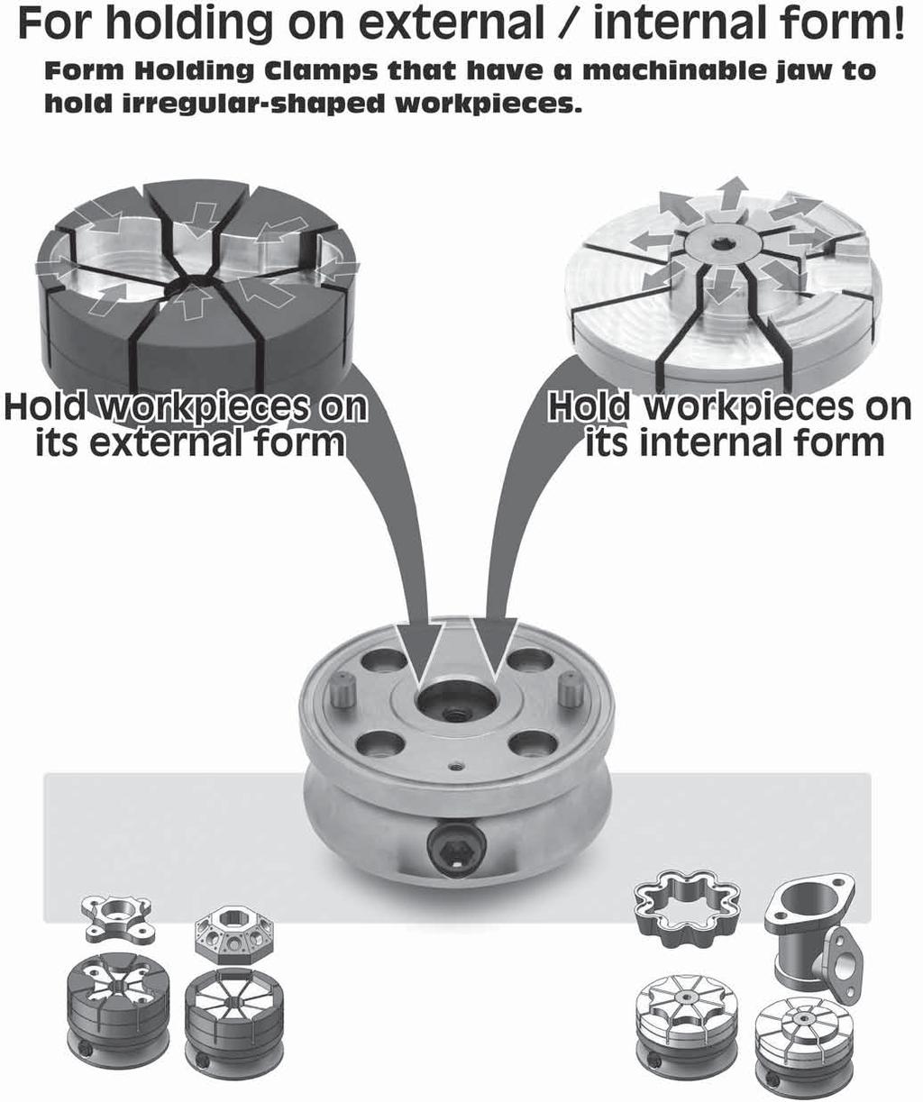
3 Two optional jaws clamping workpieces both on its external form and internal form. For external form holding For internal form holding Prepare the jaw Machine the jaw Mount a workpiece Tighten the cam cylinder. 3
 (H6) ±0.02 ±0.")
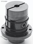
4 CP120 Body Steel (S45C) Black oxide finish Shaft / Locking Screw Steel (SCM435) Black oxide finish Quenched and tempered Jaw Aluminum (A7075) Blue Housing / Locking Ring Steel (S45C) Black oxide finish Part Number A B C D E F G H J K L M N P Q R (G6) (H6) ±0.02 ± M M Part Number S T U V W Z Clamping Force Allowable Screw Torque Weight (G6) (N.m) (kg) M4x0.7 M x l 4, M5x0. M 10x1.5-20L 6, Technical Data: Part locating repeatability: ±0.03 Jaw locating repeatability: ±0.02 Included: 1 of locking ring 1 of diamond pin 1 of socket-head cap screw Notes: Never tighten the locking screw without a part mounted, to avoid damage and deformation. Do not machine the jaw deeper than allowed.. 4
5 CP120 Features: Hole Preparation 4 G 45 Unclamped Clamped When the locking screw is tightened, the central bottom part of the jaw is pulled down. P.C.D F At the same time the 4 jaw sections tilt toward the center to clamp the circumference of a part. D B The diaphram clamping mechanism allows securely clamping a part with 4 jaw sections. Different irregularly-shaped parts can be clamped. 0.15mm clamping stroke of each jaw section is perfect for clamping of lost-wax parts, die-cast parts, extruded parts, solid-drawn parts, prefinished parts, etc. How To Use Body Mounting Socket-Head Cap Screws Diamond Pin Body Insert an included diamond pin into the body for locating, and then secure the body to the fixture plate with 4 socket-head cap screws. Jaw Setting Socket-Head Cap Screw Jaw Parallel Key Locking Screw Engage the keyway on the bottom of the jaw with the parallel key on the top of the body, and then secure the jaw with an included cap screw. Note : At jaw installation, ensure the locking screw is fully loosened by turning counterclockwise until it stops. Part Number A B C D E F (H7) (G7) (±0.02) (P.C.D.) (Bolt) Jaw Machining E 6 Locking Ring (1)Set the locking ring in the jaw. (using a bolt facilitates setting) Machinable Depth Locking Ring 6 Part Setting M6X1 MX1.25 Socket-Head Cap Screw Note : Locate the locking ring above the cap screw's socket. Part G (2)Tighten the locking screw to clamp the locking ring(after clamping the bolt will be removed from the locking ring). (3)Machine the jaw to the contours of a part. After machining loosen the locking screw to take out the locking ring. Mount a part and then tighten the locking screw for clamping. Tightening the locking screw on the side of the body allows holding a part on its circumference. Machinable jaws allow clamping parts of various shapes. Ideal way to hold parts for machining on small-size machining centers, tapping centers, small-size 5-axis machines, CNC rotary tables, etc.. 5
6 CP121 JAWS Jaw Aluminum (A7075) Blue Locking Ring Steel (S45C) Black oxide finish K (Jaw-Removing Tapped Hole) J C (Machinable Depth) H Locking Ring F D B Part Number A B C D E F G H J K Weight (g) M4x0.7 M10x (prepared hole ø.5) M5x0. M12x (prepared hole ø 10.2) Form holding clamps Feature: Body Jaw Just changing jaws allows holding different parts. How To Remove Jaw When it is hard to remove the jaw by hand, screw a bolt into the jaw-removing tapped hole to push it against the body, for easier removal.. 6

7 CP122 Mounting-on-lathe adapters Body Steel (SCM415) Black oxide finish Carburized-hardened Part Number A B C D E F G H J Weight ±0,01 ±0,01 H7 (g) M6x deep Mx deep Form holding clamps How To Use: Chuck Using these adapters allow mounting a Form Holding Clamp on the lathe. Mounting-On-Lathe Adapter Form Holding Clamp Note : A diamond pin included with a FormHolding Clamp is not required in this combination use.. 7
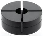
8 CP123 Wedge Style/Round Body Steel(S45C) Black oxide finished Wedge Steel(S45C) Black oxide finished Quenched & tempered Part Number D1 d H H2 D H1 H3 D2 H4 d1 Dp d2 P (g7) Part Number M w H5 M1 D4 T Clamping Force Allowable Screw Torque Weight (N) (N-m) (kg) M 6x1-25L 5 1 M3x , M 10x1.5-35L 27 M3x , Technical Information: Locating repeatability: ±0.0 Furnished Parts: 1 of locking button Spring pin (ø 5x10L for ) (ø 6x14L for ) Notes: Do not tighten the clamping screw without the workpiece set to prevent damage and deformation. Do not machine the jaws beyond the machinable depth..
9 CP123 Wedge Style/Round Features: - When the clamp screw is tightened, both jaws tilt toward the center to clamp the circumference of the workpiece. - The clamping stroke is 0.5mm. - Cutting the machinable jaw to the contours of parts allows holding parts of different shapes. - Simple and compact design permits multiple-parts holding arrangement. Clamping Screw How To Use Mounting-Hole Dimensions 4-M2 45 Dp d3 d4 Lf1 Lf Part Number d3 Lf d4 Lf1 P1 M2 Dp P M4 0.7 M How To Machine Jaws Setting the locking button Insert the locking button into the jaw, and then tighten the clamp screw to fasten the locking button. (Using a cap screw facilitates setting) Cap Screw Locking Button Locking Button Clamping Screw Note:The locking button must be inserted onto the bottom. Machining the jaw Cut the jaw to the contours of the part. Loading the part Loosen the clamping screw to remove the locking button. Load the part and tighten the clamping screw for clamping. Part Clamping Screw Note:Do not cut beyond the machinable depth.. 9
 4-d1 W1 d 3 H1 H2 (Machinable Depth) H Across Flats W3 P1 H4 4-d1 M Hex Socket-Head Cap Screw W1 d 3 H1 H2 (Machinable Depth) H Across Flats W3 P1 M Hex Socket-Head Cap Screw H4")

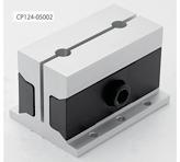
10 CP124 Wedge Style/Square / Body Aluminum(A6N01) Anodized Natural color Wedge Steel(SCM440) Black oxide finished Quenched & tempered / L P 2-d2 (Locating Holes) L P 2-d2 (Locating Holes) 4-d1 W1 d 3 H1 H2 (Machinable Depth) H Across Flats W3 P1 H4 4-d1 M Hex Socket-Head Cap Screw W1 d 3 H1 H2 (Machinable Depth) H Across Flats W3 P1 M Hex Socket-Head Cap Screw H4 D M1 T W H / / W H3 Locking Button (Included) Part Number W1 d L H H2 W H3 H1 D2 d1 P P1 M (H7) M 6x1-25L M x l M10x1.5-40L M12x L Part Number W3 H4 M1 D T Clamping Force Allowable Screw Torque Weight (N) (N-m) (kg) M3x , M3x , M3x , M3x , Technical Information: Locating repeatability: ±0.0 Furnished Parts: 1 of locking button for / of locking button for / of parallel pin (m6 tollerance) (ø 5x10L for / ) (ø 6x15L for / ) Notes: Do not tighten the clamping screw without the workpiece set to prevent damage and deformation. Do not machine the jaws beyond the machinable depth.. 10
11 CP124 Wedge Style/Square Features: When the clamp screw is tightened, both jaws tilt toward the center to clamp the circumference of the workpiece The clamping stroke is 0.5mm. Cutting the machinable jaw to the contours of parts allows holding parts of different shapes. Simple and compact design permits multiple-parts holding arrangement. Clamp Screw Mounting-Hole Preparation P2 ±0.02(only for d3) Lf 4-M2 Part Number d3 Lf M2 P2 P3 P3 2-d3 (Locating Hole) Use the included parallel pin for locating M M M M How To Machine Jaws Setting the locking button Insert the locking button into the jaw, and then tighten the clamp screw to fasten the locking button. (Using a cap screw facilitates setting) (Cap Screw) Locking Button Clamping Screw Locking Button Note:The locking button must be inserted onto the bottom. Machining the jaw Cut the jaw to the contours of the part. Loading the part Looen the clamping screw to remove the locking button. Load the part and tighten the clamping screw for clamping. Part Note:Do not cut beyond the machinable depth. Application Examples Single-station mode on the short-type clamp Dual-station mode on the long-type clamp Single-station mode on the long-type clamp. 11
 Key Point Can hold on external/internal form. 0.")
12 CP125 Body S45C Steel Electroless nickel plated Pull Cylinder SCM415 Steel Carburized-hardened Black oxide finish Cam Cylinder SCM435 Steel Quenched & tempered Black oxide finish Note: Jaws must be ordered separately 45 Dp M1 M-For Socket-Head Cap Screws P D P 2-Round Locating Pins (for jaw locating) Key Point Can hold on external/internal form A H H2 H3 Across Flats W A H1 Cam Cylinder D1 2-Holes for diamond pin Part Number D H D1 H1 M H2 Dp P W H3 M1 (± 0.01) (g6) (± 0.02) M M x M M10x M M10x M M12x1.75 Part Number Allowable Screw Torque Weight (N-m) (kg) For external Form Holding Part Number Clamping Clamping Force (kn) Stroke Proper Jaws For internal Form Holding Part Number Clamping Clamping Force (kn) Stroke , , , ,1 Technical Information: ø ø ø ø 0.3 Notes: ø ø ø ø 0.3 Part locating repeatability: ±0.03 Jaw locating repeatability: ±0.02 Furnished Parts: : 1 pc. of Diamond Locating Pin : 1 pc. of Diamond Locating Pin : 1 pc. of Diamond Locating Pin : 1 pc. of Diamond Locating Pin Do not actuate clamping without a workpiece to avoid damage and deformation. Tightening with torque greater than the allowable screw torque will lower the durability of the jaw. Related Products: /...29/...30/...31: Jaws for External Form Holding /...33/...34/...35: Jaws for Internal Form Holding. 12
13 CP125 Features: Two optional jaws allow clamping a workpiece both on its external form and internal form. JAW FOR EXTERNAL FORM HOLDING (CP126) TAPERED SCREW FOR INTERNAL FORM HOLDING (CP 127-B) JAW FOR INTERNAL FORM HOLDING (CP 127) FORM HOLDING CLAMP (CP 125) How to use: Mounting-Hole Dimensions 4-M2 45 Dp1 d1 d2 Part Number d1 H Lf d2 G Lf P1 ± M2 M 6 1 M 1.25 M M Dp Lf1 Lf P1 Installation Instructions Hex-Socket Head Cap Screw Insert an included diamond pin into the body for locating and secure the body to the fixture plate with 4 socket-head cap screws. Note: Use either of the holes for diamond locating pin for your application. FORM HOLDING CLAMP Diamond Locating Pin (included) Dimensions of Diamond Locating Pin Part Number Diameter ø 6h6 ø h6 ø 10h6 ø 12h6. 13
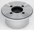
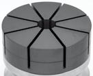
14 CP126 JAWS for external Form Holding Blue Jaw Aluminum (A7075) Locking Ring Steel (S45C) Black oxide finish M1 D1 D d H2 H (Machinable Depth) H1 T Locking Ring M-For Hex Socket Button Head Screw 2-Locating Holes Part Number D d H1 H2 M H M1 D1 T Weight (kg) M x20l Across Flats5 29 M5x M10x20L Across Flats6 40 M6x M10x25L Across Flats6 46 M6x M12x25L Across Flats 52 Mx Proper Clamps Furnished Parts: Features 1 pc. of O-ring 1 pc. of Locking Ring 1 pc. of Hex Socket Button Head Screw The diaphram clamping mechanism allows securely clamping a part with jaw sections. 0.15mm clamping stroke of each jaw section is perfect for clamping of lost-wax parts, die-cast parts, extruded parts, solid-drawn parts, prefinished parts, etc. Unclamped Clamped When the cam cylinder is tightened, the central bottom part of the jaw is pulled down. Cam Cylinder At the same time the jaw sections tilt toward the center to clamp the external form of a part.. 14
15 CP126 JAWS for external Form Holding How To Use Jaw Mounting Insert an O-ring to the groove on top surface of the Form Holding Clamp. Set a Jaw putting its locating holes onto the round locating pins and fix it with a hex socket button head screw. Note: At jaw installation, ensure the cam cylinder is fully loosened by turning counterclockwise until it stops. Hex Socket Button Head Screw (included) CP126 JAW O-ring (included) Jaw Machining Set the locking ring in the jaw. (Using a screw facilitates setting.) (Screw) Locking Ring (included) Hex Socket Button Head Screw Note: Locate the locking ring above the button head screw's socket. Round Locating Pins Cam Cylinder Tighten the cam cylinder to clamp the locking ring. (Recommended Tightening Torque: 15N-m) After clamping the screw should be removed from the locking ring. Machine the jaw to the contours of a part. Note: Do not machine the jaw deeper than allowed. Machinable Depth Workpiece Setting After machining loosen the cam cylinder to take out the locking ring. Mount a workpiece and tighten the cam cylinder for clamping. Locking Ring Workpiece Clamping Force(kN) Performance Curve Tightening Force(N-m) Notes Do not actuate clamping without a workpiece to avoid damage and deformation.tightening with torque greater than the allowable screw torque will lower the durability of the jaw.. 15

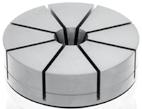
16 CP127 JAWS for internal Form Holding H D H2 H1 (Machinable Depth) Jaw Aluminum (A7075) 2-Locating Holes Silver Part Number D H1 H2 H Weight (kg) Proper Clamps Proper Screws Furnished Parts: 1 pc. of O-ring CP127-B TAPERED SCREWS for internal Form Holding L L1 W D D1 Body M SCM435 Steel Quenced and tempered Electroless nickel plated Part Number D L M L1 D1 W Weight (g) M x M10x M10x M12x Proper Jaws Features The tapered screw expands the jaws towards eight directions to hold different irregularly-shaped parts securely. 0.15mm clamping stroke of each jaw section is perfect for clamping of lost-wax parts, die-cast parts, extruded parts, solid-drawn parts, prefinished parts, etc. Clamped Unclamped When the cam cylinder is tightened, the tapered screw is pulled down. At the same time the jaw sections expand to clamp the internal form of a part. Cam Cylinder. 16
17 CP127 JAWS for internal Form Holding How To Use Jaw Mounting Insert an O-ring to the groove on top surface of the Form Holding Clamp. Set a Jaw putting its locating holes onto the round locating pins and fix it with a tapered screw. Note: At jaw installation, ensure the cam cylinder is fully loosened by turning counterclockwise until it stops. CP127-B SCREW CP127 JAW O-ring (included) Round Locating Pins Cam Cylinder Jaw Machining Loosen the cam cylinder fully and measure the dimension of the jaw for machining. Then tighten the cam cylinder until each jaw section expands 0.15mm. Machine the jaw to the contours of a part. Note: Do not machine the jaw deeper than allowed. Machinable Depth Workpiece Setting After machining loosen the cam cylinder to set a part and tighten the cam cylinder again for clamping. Workpiece Clamping Force (kn) Performance Curve Tightening Force (N-m) Notes Do not actuate clamping without a workpiece to avoid damage and deformation. Tightening with torque greater than the allowable screw torque will lower the durability of the jaw.. 17
18 . 1
VISES VISES JAWS CENTERING CLAMP BASE PLATE COMPACT PNEUMATIC VISE PAIR OF CLAMPS PAIR OF POSITIONING KEYS PAIR OF POSITIONING KEYS VISES
 CENTERING CLAMP JAWS BASE PLATE Part No. CP170 Part No. CP175 Part No. CP179 COMPACT PNEUMATIC VISE Part No. AMLFV-S PAIR OF CLAMPS Part No. MVAC-CS PAIR OF POSITIONING KEYS Part No. MVAC-SK PAIR OF POSITIONING
HANDLES & KNOBS HANDLES HANDLES & KNOBS COMPACT CAM HANDLES QLCCS ADJUSTABLE-TORQUE HANDLES CAM HANDLES CAM HANDLES. Part No. QLCCS. Part No.
 & & ADJUSTABLE-TORQUE Part No. ATCL COMPACT CAM QLCCS Part No. QLCCS CAM CAM Part No. QLCA Part No. QLCL & ONE-TOUCH LOCKING Part No. OTLK POINTER PLATE Part No. OTLK-A TORQUE LIMITING Part No. CTK & ATCL
WORK SUPPORTS WORK SUPPORTS
 COMPACT PNEUMATIC Part No. AMNS-S PNEUMATIC Part No. BJ370 PRECISION SUPPORT Part No. BJ371 Part No. BJ350 CYLINDRICAL Part No. BJ351 COIL SPRINGS FOR CYLINDRICAL Part No. BJ351-C REMOTE-CONTROL UNITS
CAM SYSTEM. Eccentric self-locking clamping devices. Set. CAM SYSTEM t. CAM SYSTEM t. Set. CAM SYSTEM s pag CAM SYSTEM s pag.
 Eccentric self-locking CAM SYSEM Set CAM SYSEM t pag. 12 CAM SYSEM t pag. 126 Set CAM SYSEM s pag. 127 CAM SYSEM s pag. 128 EDGE CLAMP pag. 130 123 CAM-SYSEM eccentric self-locking he CAM SYSEM has been
Clamping devices 521
 Clamping devices 521 522 Product overview Clamping devices Adjustable straps K0001 Hook clamps K0012 Goose-neck straps with long slot K0002 Page 526 Hook Clamps with collar K0013 Page 535 Equipped clamps
Clamping bolts Eccentrical cams clamping units
 2.3 Shaft Clamping bolts Eccentrical cams clamping units 2.9 2.8 2.7 2.6 2.5 2.4 2.3 2.2 2.1 2.3 Clamping bolts, Eccentrical cams, Shaft clamping units Page 641 2.3 Clamping bolts, Eccentrical cams, Shaft
Pull-down clamps. No Low height clamping jaws, model Bulle
 Pull-down clamps The wedge action of clamping jaws is the characteristic feature of these pull down clamps. It causes the pull down effect, which presses the workpiece against both, stop and machine table.
5-axis clamping system compact
 5-axis clamping system compact 395 5-axis clamping system compact Function We are setting standards with the new KIPP 5-axis clamping system compact in this field. The system was specifically designed
5-AXIS MACHINING SCS QUINTUS WWW. WORKHOLDINGSOLUTIONSGROUP. COM
 WORKHOLDING SOLUTIONS FOR -AXIS MACHINING SCS MC QUINTUS ONE system / MANY solutions WWW. WORKHOLDINGSOLUTIONSGROUP. COM MCCLAMPING S YSTEM for -axis machining MC + Quintus... MC Clamping System Free access
ONE-TOUCH CLAMPS ONE-TOUCH CLAMPS ONE-TOUCH CLAMPS SWING CLAMPS SWING CLAMPS WITH CAM HANDLE SWING CLAMPS SWING CLAMPS WITH ADJUSTABLE HANDLE
 SWING Part No. QLSWC SWING WITH CAM HANDLE Part No. QLSWC SWING WITH ADJUSTABLE HANDLE Part No. QLSWC SWING (Standard) Part No. QLSW MACHINABLE CLAMP ARMS FOR STANDARD SWING Part No. QLSW-SH SWING (Heavy)
Zero Point Clamping System. ZERO lock BALL lock
 Zero Point Clamping System ZERO lock BALL lock kap3 kap 263 Technical information regarding ZERO lock Zero Point Clamping System Application The modularly designed, flexible ZERO lock Zero-Point Clamping
 .. 8. 2. 9. 22. 0.. 2.. 2. 2.... 28. 29.... 8. 9. PBL Universal Ball-Lock Power Castings or forgings can be.d. or I.D. clamped Grips on taper up to 0 Jaws pivot up to to grip on uneven surfaces Ideal for
PRODUCTION VISES. Vises. Bock Quick Change Fixturing. 5-Axis Production Vises
 Vises Introduction to Design... 74 75 VMC/HMC Solutions...76 77 Ball Lock Mounting System...78 79 Production Vises 4" (100 mm) Production Vises... 80 81 6" (150 mm) Production Vises...82 83 Self Centering
DIVIDING EQUIPMENT DIVIDING EQUIPMENT
 64 DIVIDING EQUIPMENT 65 D-01 UNIVERSAL TILTING ROTARY TABLE Model: HUT-300 QUICK MANUAL INDEXING. Suitable for milling, boring, shaping, drilling, dividing, setting angles and for circular cutting. Tilting
Hardinge FlexC Dead-Length Collet System Style DL. Installation Instructions and Parts Lists. FlexC Collet System Style DL Instructions B-152
 Hardinge FlexC Dead-Length Collet System Style DL Installation Instructions and Parts Lists 1 General Safety Information Before installing the Hardinge FlexC Collet System on your machine tool, thoroughly
IDEAL FOR 5-AXIS MACHINING
 IDEAL FOR 5-AXIS MACHINING Without additional foundations or special jaws, the RZM centric vice holds the workpiece securely and does this with a minimal interference contour. The clamping spindle is located
T-Slot Clamps Rotagrip Ltd Tel Website
 T-Slot Clamps 12150 Body: heat treated steel. Clamp: brass. Packed in pairs. For use in T-slots of machine tables. For replacement clamping screws see 12112. Hex. key not included. Order No. Slot size
IDEAL FOR 5-AXIS MACHINING
 IDEAL FOR 5-AXIS MACHINING Without additional foundations or special jaws, the RZM centric vice holds the workpiece securely and does this with a minimal interference contour. The clamping spindle is located
5-Axis Machine Tools from SMW-AUTOBLOK
 5-Axis Machine Tools from SMW-AUTOBLOK 5-Axis Machine Tools ensures the following advantages: Ideal suitable for OP 10 use ST5-2G also suitable for OP 20 use Jaws with SinterGrip clamping inserts for clamping
Hardinge FlexC Dead-Length Collet System Style A. Installation Instructions and Parts Lists. FlexC Collet System Style A Instructions B-153
 Hardinge FlexC Dead-Length Collet System Style A Installation Instructions and Parts Lists 1 General Safety Information Before installing the Hardinge FlexC Collet System on your machine tool, thoroughly
Hardinge FlexC Dead-Length Collet System Style DL 42mm. Installation Instructions and Parts Lists
 Hardinge FlexC Dead-Length Collet System Style DL 42mm Installation Instructions and Parts Lists 1 General Safety Information Before installing the Hardinge FlexC Collet System on your machine tool, thoroughly
Collet Closer & Tailstock Options
 Collet Closer & Tailstock Options Fail-Safe Collet Closers Spring-close, air-to-open for fail-safe operation (85psi max) Part remains clamped even if loss of air should occur Non-adjustable grip force
Making Cam Action Edge Clamps, version 2 *
 Making Cam Action Edge Clamps, version 2 * By R. G. Sparber 01/15/2008 Copyleft protects this article. The idea of making these clamps came from Brian Lamb. They work great. If you have more money than
Dimensions of the machine spindle heads in accordance with DIN The latest issue of the DIN sheet is binding
 Info Dimensions of the machine spindle heads in accordance with DIN The latest issue of the DIN sheet is binding DIN 55026 from taper size 4 with driver. Spindle head Size C1 C2 D hole count outer olt
EPPA2-KIT DUAL MONITOR ARM CONVERSION
 EPPA2-KIT DUAL MONITOR ARM CONVERSION EPPA2-KIT Rev A 10/17 Model EPPA2-KIT-XXX ASSEMBLY AND ADJUSTMENT EPPA2-KIT PARTS AND TOOLS PLEASE REVIEW these instructions before beginning the assembly and adjustment
NEW RÖHM VICE NOVELTIES. RKE-M and RZM (size 92)
") NEW RÖHM VICE NOVELTIES RKE-M and RZM (size 92) NC-COMPACT-VICE RKE-M MANUALLY OPERATED APPLICATION Particularly suitable for use on machining centers and palletisers. TYPE Clamping system mechanical without
NEW RÖHM VICE NOVELTIES RKE-M and RZM (size 92) NC-COMPACT-VICE RKE-M MANUALLY OPERATED APPLICATION Particularly suitable for use on machining centers and palletisers. TYPE Clamping system mechanical without
c. Pins, bolts, and retaining rings b. Washers, locking nuts, and rivets
 62 20 HW 8: Fasteners / Force, Pressure, Density Mechanical Systems DUE Mon, 11/21/16 Start of class Check link on website for helpful fastener information Please use a scantron. Material is based primarily
adaptivemechanical adaptive
 Mechanical clamping elements mechanical 6 Content Product group 6 Sliding clamp, mechanical 6.2210 Clamping block, mechanical 6.2212 High-pressure spindle, mechanical with integral wedge system 6.2270
Lathe. A Lathe. Photo by Curt Newton
 Lathe Photo by Curt Newton A Lathe Labeled Photograph Description Choosing a Cutting Tool Installing a Cutting Tool Positioning the Tool Feed, Speed, and Depth of Cut Turning Facing Parting Drilling Boring
OPERATING INSTRUCTIONS 5-AXIS CLAMPING SYSTEM + ACCESSORIES
 OPERATING INSTRUCTIONS 5-AXIS CLAMPING SYSTEM + ACCESSORIES 1 Contents 1. Introduction 2. Safety instructions and precautions 3 Operating the clamp 3.1 Clamp set up 3.2 Sequence for clamp set up 3.3 Adjusting
Engineering Data Gas Spring Clamps
 Engineering Data Gas Spring Clamps The New Industry Standard This product may be covered by one or more patents or patent applications. See http://www.standardlifters.com/patents.html for details. 12/13
ROTARY TABLE OPERATION AND SERVICE MANUAL HORIZONTAL AND VERTICAL. Horizontal & Vertical. Rotary Table (HVRT) Tilting Rotary Table
 Tilting Rotary Table") Horizontal & Vertical Rotary Table (HVRT) OPERATION AND SERVICE MANUAL Tilting Rotary Table Horizontal & Vertical Rapid Indexer VERTICAL AND HORIZONTAL ROTARY TABLE This Horizontal & vertical table is
Horizontal & Vertical Rotary Table (HVRT) OPERATION AND SERVICE MANUAL Tilting Rotary Table Horizontal & Vertical Rapid Indexer VERTICAL AND HORIZONTAL ROTARY TABLE This Horizontal & vertical table is
LOW PROFILE CLAMPING. Jergens OK-Vise. Micro Clamps
 Jergens OK-Vise Serrated and Smooth Jaws...296 Machinable Jaw... 297 Mounting Jaw... 298 Self-Adjustable...299 Pull-Down... 300 301 Economy... 302 Low Profile Comparison Chart... 303 Multi-Rail RM System...
MACHINE TOOL ACCESSORIES
 VERTICAL 5-C COLLET VISE SERIES 344: VERTICAL 3-C COLLET VISE SERIES 344: : 2-1/2 x 7-3/4 Height: 4 Small movement of lever opens or closes collet. 2030000 CAM OPERATED 5-C HORIZONTAL/VERTICAL COLLET FIXTURE
It s a good idea to identify the Front and Rear cylinder heads. before starting the teardown process.
 It s a good idea to identify the Front and Rear cylinder heads using a paint pen before starting the teardown process. Use a 17/64 drill bit (or 6mm if you have metric drills or round stock) to lock the
Special Thumb Screw Order Form
 Special Thumb Screw Order Form QUOTE FOR: ORDER FOR: Name: Company: Address: QUANTITY: Phone #: City: State: Zip: Email Address: FILL IN YOUR DIMENSIONS write directly over light blue type* write clearly
By C.W. Woodson From the pages of Model Craftsman magazine June, 1937
 By C.W. Woodson From the pages of Model Craftsman magazine June, 1937 As shown in Fig. 1, the tool post grinder for which plans are given here can be used to finish up delicate work to more accurate dimensions
Hardinge FlexC Collet System Style D 65mm
 Hardinge FlexC Collet System Style D 65mm Installation Instructions and Parts Lists 1 General Safety Information Before installing the Hardinge FlexC Collet System on your machine tool, thoroughly read
Installing CNC Stepper Motor Mounts On A Sherline Mill
 Installing CNC Stepper Motor Mounts On A Sherline Mill P/N 6700 (6710 Metric) 5000/5100/5400/5410 Mills P/N 6705 (6715 Metric) 2000/2010 Mills USING THE TEMPLATE BLOCKS TO LOCATE NEW MOUNTING HOLES FOR
Jaw chuck B-Top3 STANDARD CHUCKS. 215 Variant. Jaw chuck B-Top3. Technical data. Size. B-Top3
 STANDARD CHUCKS. Technical data A AJ DH AI AT AW T BQ AS Size 215 ariant B-Top3 Concentricity [mm] Max. clamping force [kn] Max. axial drawtube force [kn] RPM n max. [1/min.] Stroke per jaw [mm] Ø Capacity
Hardinge FlexC Dead-Length Collet System Style A 80mm. Installation Instructions and Parts Lists. FlexC 80mm Collet System Style A Instructions B-170B
 Hardinge FlexC Dead-Length Collet System Style 80mm Installation Instructions and Parts Lists 1 General Safety Information efore installing the Hardinge FlexC Collet System on your machine tool, thoroughly
ASSEMBLY AND ADJUSTMENT
 EPPA MONITOR ARM EPPA Rev A 10/17 Model EPPA-XXX ASSEMBLY AND ADJUSTMENT EPPA MONITOR ARM PARTS AND TOOLS PLEASE REVIEW these instructions before beginning the assembly and adjustment procedures. Check
INSTRUCTIONS FOR USE B2 FORM KNURLING TOOL
 INSTRUCTIONS FOR USE B2 FORM KNURLING TOOL Contents CONTENTS 1. General... 2 1.1 Introduction... 2 1.2 Tool Construction... 3 2. B2 Tools... 6 2.1 Technical Data... 6 2.2 Overview: Main components... 7
MFG 316 Chapter 4 //Workholding Principles
 Workholding Principles All devices that grip, hold, chuck, or retain a workpiece in order to perform a manufacturing operation. Force=hydraulic, pneumatic, electrical, mechanical Force multiplication by
Leveling Feet, Base Plates and Casters
 Leveling Feet, Base Plates and Casters 77 Leveling Foot 1 1 Fastening to profile end Fastening in T-slot of profile For leveling tables and light equipment. Ratchet-type height adjustment requires no tools.
HEICO FASTENING SYSTEMS. Simple Fast Reliable HEICO-TEC TENSION NUT
 HEICO FASTENING SYSTEMS Simple Fast Reliable HEICO-TEC TENSION NUT WWW.HEICO-TEC.COM HEICO-TEC TENSION NUT SIMPLE FAST RELIABLE For a secure joint with a HEICO-TEC tension nut, no electric, hydraulic,
TCF 160 / TCF 200 / TCF 224 / TCF 250 TCF 275 / TCF 300 HEAVY CENTRE LATHES
 TCF 160 / TCF 200 / TCF 224 / TCF 250 TCF 275 / TCF 300 HEAVY CENTRE LATHES BASIC PARAMETERS 3-guideways bed Max. torque on spindle Nm Max. weight of workpiece between centre 30 tonnes Turning length 3,000
Building a vertical wobbler
 Building a vertical wobbler I wanted to build a simple steam engine that would also run on compressed air. At Chris Heapy s website (http://easyweb.easynet.co.uk) I found drawings of a small double acting
LEG CURL IP-S1315 INSTALLATION INSTRUCTIONS
 LEG CURL IP-S35 INSTALLATION INSTRUCTIONS Copyright 2009. Star Trac by Unisen, Inc. All rights reserved, including those to reproduce this book or parts thereof in any form without first obtaining written
PPC Series Precision Power Chucks
 Precision Workholding Technology PPC Series Precision Power Chucks www.microcentric.com The World s Most Accurate Power Chuck Improve productivity and lower costs by enhancing workpiece quality...... through
TOOLS/PROCESSING SERVICES TOOLS + PROCESSING SERVICES
 TOOLS/PROCESSING SERVICES 7 TOOLS + PROCESSING SERVICES MINITEC PROFILE SYSTEM 583 TOOLS/PROCESSING SERVICES TOOLS s l oot TOOLS 584 MINITEC PROFILE SYSTEM BALL-HEADED KEY - Chrome plated, with handle
TECHNICAL INFORMATION Models No.
 TECHNICAL INFORMATION Models. Description 6207D, 6217D, 6237D,, 9.6V, 12V, 14.4V Cordless Driver Drills 10mm (3/8") 12V, 14.4V, 18V Cordless Driver Drills 13mm (1/2") CONCEPT AND MAIN APPLICATIONS These
Face Drivers FSP / FSPB
 4 Face Drivers FSP / FSPB NEIDLEIN-SPANNZEUGE GmbH Face Drivers FSP / FSPB with drive disk and movable center pin The entire surface of the workpiece can be tooled and finished by clamping with a maximum
NEWS Part. N /0 MINITEC NEWS
 NEWS 2009 Part. N 95.0423/0 MINITEC NEWS 2009 1 TABLE OF CONTENT INTRODUCTION CONTENTS 3 END CAP Z WITH HAMMER TAPS 3 END CAP 45X45 VA 4 ANGLE 25 GD-Z 4 ANGLE 45X90 GD-Z 5 ANGLE 90 GD-Z 5 HINGE 19 S 6
INSTALLATION INSTRUCTION RRU DOUBLE LIGHT POLE MOUNT
 INSTALLATION INSTRUCTION RRU Double Light Pole Mount for installation of two RRU units on mast, towers or other vertical structures. CUE DEE YOUR INNOVATIVE PARTNER 1 CONTENTS 1. PRODUCT COVERED IN THIS
'\QDPLF# Tooling Catalog 20 0DFK#0DFKLQH#5HVRXUFHV/#,QF1# Phone: (949) Fax : (949)
 Fax : (949)") '\QDPLF# 0DFK#0DFKLQH#5HVRXUFHV/#,QF1# Tooling Catalog 20 Phone: (949) 481-3375 Fax : (949) 481-8559 Multi-Position Tool Stations When fast changeover is critical Ideal for mounting groups of tools for
'\QDPLF# 0DFK#0DFKLQH#5HVRXUFHV/#,QF1# Tooling Catalog 20 Phone: (949) 481-3375 Fax : (949) 481-8559 Multi-Position Tool Stations When fast changeover is critical Ideal for mounting groups of tools for
Machine Your Fishing Reel
 Machine Your Fishing Reel You will be well prepared for the coming season if you start on this smooth-running job now. IF you're an enthusiastic fisherman and have a lathe in your workshop, we'll say no
Technical T-A & GEN2 T-A GEN3SYS APX. Revolution & Core Drill. ASC 320 Solid Carbide. AccuPort 432. Page CONTENTS. Set-up Instructions 256
 Technical ASC 0 Solid Carbide CONTENTS Page Set-up Instructions 6 AccuPort 4 Recommended Speeds & Feeds 60 Guaranteed Application Request Form 99 +44 (0)84 400 900 +44 (0)84 400 0 enquiries@alliedmaxcut.com
STEVENS SUBPLATES. STEVENS ENGINEERING, INC. TOLL-FREE WEB FAX
 STEVENS SUBPLATES Spacing of hole patterns on Stevens accessories is identical to the pattern on Stevens Subplates. Insertion of the pull dowels thru bushed holes in the accessory into corresponding bushed
Hardinge FlexC Collet System Style D
 Hardinge FlexC Collet System Style D Installation Instructions and Parts Lists 1 General Safety Information Before installing the Hardinge FlexC Collet System on your machine tool, thoroughly read this
PRODUC TION VISES. Vises. 5-Axis Production Vises
 Introduction to Design...104 105 VMC/HMC Solutions...106 107 Ball Lock Mounting System...108 109 Production Vises 4" (100 mm) Production Vises...110 112 6" (150 mm) Production Vises...113 115 Short 6"
Technical features. Positive Taper Lock System for manual tool clamping. Technical features:
 clamping set Technical features The RÖHM- was specially designed for the positive taper lock clamping taking particulary into account the necessity of manual clamping. Technical features: strong design
Tools for the Mechanical Mounting and Dismounting of Rolling Bearings
 Tools for the Mechanical Mounting and Dismounting of Rolling Bearings Contents Page Mechanical mounting and dismounting of rolling bearings... 2 Cylindrical bearing seats... 2 Tapered bearing seats...
MC-CVR-1. Király Trading KFT H-1151 Budapest Mogyoród útja
 MC-CVR-1 Király Trading KFT H-11 Budapest Mogyoród útja -14 E-mail:_agi@kiralytrading.hu carver clamp Series Applications C-Style Carver Clamps A djustment screw is shielded and out of the work area Ideal
Special Z-Axis Ballscrew Replacement
 To replace Z-axis ballscrew without removing X-axis components When rebuilding an OmniTurn slide, all the precision components are replaced. The tooling plate and saddle are removed to gain access to the
EDGE2 DUAL MONITOR ARM
 EDGE2 DUAL MONITOR ARM EDGE2 Rev A 2/17 Model EDGE2-SLV Model EDGE2-BLK Model EDGE2-WHT ASSEMBLY AND ADJUSTMENT EDGE2 DUAL MONITOR ARM PARTS AND TOOLS PLEASE REVIEW these instructions before beginning
Industrial Drill Chucks with Key. For Stationary Machines and Portable Drilling Machines. Diameter (mm)
") Drilling Industrial Drill Chucks with Key For Stationary Machines and Portable Drilling Machines Specifically designed for stationary drilling, turning, milling and wood working machines The one-piece
Drilling Industrial Drill Chucks with Key For Stationary Machines and Portable Drilling Machines Specifically designed for stationary drilling, turning, milling and wood working machines The one-piece
TOOLS REQUIRED Metal Wood Wood and Metal Screws. #16 Drill #12-24 Tap. 1/8 Drill
 DEVICES COVERED IN THIS DOCUMENT: 4700S Surface Vertical Rod Device 4700SF Fire Exit Surface Vertical Rod Device TOOLS REQUIRED Metal Wood Wood and Metal Screws Sex Bolts #7 Drill ¼ -20 Tap #16 Drill #12-24
STRENGTH Aligned teeth provide superior gripping power over standard vertical teeth. STRENGTH Diamond serrated jaws provide a firm grip
 STRENGTH Aligned teeth provide superior gripping power over standard vertical teeth STRENGTH Diamond serrated jaws provide a firm grip PLIERS AND SNIPS Locking Pliers Slip Joint Pliers Electrician s Pliers
CHICKEN COOP & CHICKEN RUN. Tools required for assembly (not included)
") CHICKEN COOP & CHICKEN RUN ASSEMBLY MANUAL SKU# 6839 Tools required for assembly (not included) Distributed by: TRACTOR SUPPLY COMPANY 0 VIRGINIA WAY, BRENTWOOD, TN 3707 For customer support, call: -888-376-960
CHICKEN COOP & CHICKEN RUN ASSEMBLY MANUAL SKU# 6839 Tools required for assembly (not included) Distributed by: TRACTOR SUPPLY COMPANY 0 VIRGINIA WAY, BRENTWOOD, TN 3707 For customer support, call: -888-376-960
M2 Assembly. M2 Sub-Assemblies mm Belt Sub-Assembly mm Belt Sub-Assembly Spider Sub-Assembly... 4
 M2 Assembly Table of Contents M2 Sub-Assemblies... 3 630mm Belt Sub-Assembly... 3 702mm Belt Sub-Assembly... 3 Spider Sub-Assembly... 4 Idler Bolt Sub-Assembly... 8 Y Motor Sub-Assembly... 9 X Motor Sub-Assembly...
MANUFACTURING TECHNOLOGY
 MANUFACTURING TECHNOLOGY UNIT V Machine Tools Milling cutters Classification of milling cutters according to their design HSS cutters: Many cutters like end mills, slitting cutters, slab cutters, angular
Wrenches. Wrenches. F o r P. r o f e. s s i o. n a l s. .. S i. n c e 1
 F o r P r o f e Klein s line of wrenches are forged from the finest steel and are designed to deliver great strength, and long working life. Regardless of the job type, Klein has a wrench that will help
INSTRUCTIONS
 IMPORTANT: THIS IS A HIGH PERFORMANCE PART AND IMPROPER INSTALLATION COULD RESULT IN INJURY OR DEATH! NEVER WORK UNDER AN AUTOMOBILE THAT IS NOT PROPERLY SUPPORTED AND BLOCKED FROM ROLLING. NO CREDIT OR
KELTON CARVING JIG Guide for Use
 KELTON CARVING JIG Guide for Use The Kelton Carving Jig has been designed to securely hold a work piece at the desired angle and working height. While it will greatly benefit wood tuners and carvers, its
Example workpieces: - Gearbox casing. Example format: - Diameter 800 mm
 RADIAL CHUCKS SAV 260.99-RSF 3 + 3 JAW CHUCKS - 3 + 3 jaw chuck with two independently actuated clamping circles - Easily adaptable from centred to balanced operation - Jaw stroke 15 mm (Stroke per jaw)
Installing CNC Stepper Motor Mounts On A Sherline Lathe
 Installing CNC Stepper Motor Mounts On A Sherline Lathe P/N 6720 (6725 Metric) 4000/4100/4500/4600 Lathes P/N 6730 (6735 Metric) 4400/4410 Lathe USING THE TEMPLATE BLOCKS TO LOCATE NEW MOUNTING HOLES FOR
Advantages, Function and Characteristics of the DMwriter MX.
 DMwriter MX All-in One Overview Advantages, Function and Characteristics of the DMwriter MX. The DMwriter MX Marking Head was designed as an easy to use, economical, spindle actuated permanent marking
High Precision Air Chucks
 Precision Workholding Solutions High Precision Air Chucks www..com Improve productivity and lower the cost of secondary machining operations..... through high concentricity. Holding close concentricity
mila-wall (Series100) General Operating Instructions page 1 of 15
 General Operating Instructions page 1 of 15") mila-wall (Series100) General Operating Instructions page 1 of 15 Step #1: Before setting up walls, lower adjustable leveling feet on each panel approximately 1". This will allow access to the threaded
mila-wall (Series100) General Operating Instructions page 1 of 15 Step #1: Before setting up walls, lower adjustable leveling feet on each panel approximately 1". This will allow access to the threaded
BHJ Products, Inc. Parts List & Instructions
 Product Name: O-Ring Groove Cutter Adjustable Tool Block Upgrade Page 1 of 5 Prototype Kit Contents: 1x Adjustable Tool Block 1x Adjustable Tool Holder 1x Graduated Adjusting Screw 1x 1/8 Registration
. Dimensions of Machine Spindle Heads in Compliance with DIN The most recent editions of the DIN standards are binding
 ß Clamping tools. Dimensions of Machine Spindle Heads in Compliance with DIN The most recent editions of the DIN standards are binding DIN 5506 Taper sizes 4 and above with driver. Spindle No. of holes
VARIABLE SPEED WOOD LATHE
 MODEL MC1100B VARIABLE SPEED WOOD LATHE INSTRUCTION MANUAL Please read and fully understand the instructions in this manual before operation. Keep this manual safe for future reference. Version: 2015.02.02
Hardinge FlexC Dead-Length Collet System Style DL 80mm. Installation Instructions and Parts Lists
 Hardinge FlexC Dead-Length Collet System Style DL 80mm Installation Instructions and Parts Lists 1 General Safety Information Before installing the Hardinge FlexC Collet System on your machine tool, thoroughly
Precision Chucks for Improved Accuracy and Increased Productivity
 Precision Workholding Technology Precision Chucks for Improved Accuracy and Increased Productivity Precision Air Chucks (Self Contained Design) MicroCentric Precision Air Chucks feature a patented open
MODEL T10050 RIGHT ANGLE IRON BENDER INSTRUCTIONS
 MODEL T10050 RIGHT ANGLE IRON BENDER INSTRUCTIONS Damage to your eyes, face, and hands could result from using this item without proper protective gear, such as safety glasses or a face shield, and gloves.
Door window. Front door window, assembly overview
 64-50 Door window Front door window, assembly overview 1 - Window channel Pushed onto flange 2 - Door window Removing Page 64-52 Adjusting Page 64-53 3 - Door 4 - Outer window channel Pushed onto flange
5-Axis Machine Tools from SMW-AUTOBLOK
 -Axis Machine Tools from SMW-AUTOBLOK -Axis Machine Tools ensures the following advantages: Ideal suitable for OP 10 use Jaws with SinterGrip clamping inserts for clamping of workpieces with lowest depth
aluminium profile system
 aluminium profile system 63 AME System aluminium profiles overview series profiles introduction 80x80 x80 x80/180 x Aluminium profiles are provided with longitudinal grooves which can be used in conjunction
Barnside Pantry IMPORTANT NOTE Carefully remove all the parts from the carton and put them individually on a soft cloth to prevent scratch
 88 5516 653 Barnside Pantry IMPORTANT NOTE Carefully remove all the parts from the carton and put them individually on a soft cloth to prevent scratches or other damage occurring to the parts. We have
RPE Parallel Gripper- Electric Gripper Series
 1.14 RPE Parallel Gripper- Electric Gripper Series Failsafe Operation: Spring closed feature allows for full grip force during power off conditions. Electrically Actuated: Requires simple 24VDC pulsed
Table of Contents. B. Base Tool Changer...2 MC-16 Manual Tool Changer...2
 Table of Contents B. Base Tool Changer...2 MC-16 Manual Tool Changer...2 1. Product Overview... 2 1.1 Master Plate Assembly... 2 1.1.1 Optional Ratchet Knob... 2 1.2 Tool Plate... 3 1.3 Optional Modules...
50, ,000 18,800 8,000. CODE 04 ER (ER ) UPC Chuck/W ITS Central Chuck. CODE 04 ER (ER ) UPC Pallet For Alignment
 UPC Chuck/W ITS Central Chuck. CODE 04 ER (ER ) UPC Pallet For Alignment") CODE 04 ER-007826 (ER-017777) UPC Pallet For Alignment CODE 04 ER-007823 (ER-016092) UPC Chuck/W ITS Central Chuck Application To align angular position and to determine the center of UPC chucks. Please
CODE 04 ER-007826 (ER-017777) UPC Pallet For Alignment CODE 04 ER-007823 (ER-016092) UPC Chuck/W ITS Central Chuck Application To align angular position and to determine the center of UPC chucks. Please
HARDINGE Installation booklet For:
 HARDINGE Installation booklet For: L Flange Nose Dead-Length Collet Adaptation Chucks Draw Collet Read the enclosed instructions and recommendations before any installations WARRANTY & RETURN PROCEDURES
BUCK PRODUCT CATALOG
 PRODUCT CATALOG Table of Contents Technical Information. Why a BUCK?...3 Manual Chuck Selection...5 Spindle Identification for Mounting Plates...6 Obsolete Chuck Crossover...7 Parts Breakdown...8 ATSC
HARDINGE Installation booklet For: Dead-Length Collet Adaptation Chucks Stationary Collet
 HARDINGE Installation booklet For: Dead-Length Collet Adaptation Chucks Stationary Collet Read the enclosed instructions and recommendations before any installations CONTENTS Dead-Length Collet Adaptation
Table of Contents. B. Base Tool Changer...2 MC-36 Manual Tool Changer...2
 Table of Contents B. Base Tool Changer...2 MC-36 Manual Tool Changer...2 1. Product Overview... 2 1.1 Master Plate Assembly... 2 1.1.1 Optional Ratchet Knob... 2 1.2 Tool Plate... 3 1.3 Optional Modules...
DO35 MAINTENANCE INSTRUCTIONS
 CUSTOMER INFORMATION SHEET NO. 038 DO35 MAINTENANCE INSTRUCTIONS (DO35 V3 LAUNCHED PRODUCTION JUNE 2017) Table of Contents 1.0 Replacing Spindle Bushes V3... 22 2.0 Replacing Locking Mechanism V3... 6
PACKING LIST MACO V-5000
 PACKING LIST MACO V-5000 PART QTY O.D. SIZE LENGTH DESCRIPTION CHECKLIST T47P 4 5/8.050 36 Aluminum Tubing _ T43P 1 7/8.050 48 Aluminum Tubing _ T18P 1 3/4.050 48 Aluminum Tubing _ T15P 1 5/8.050 48 Aluminum
INSTALLATION INSTRUCTIONS FOR INSTALLING T-SERIES EXTRA HEAVY DUTY LEVER LOCKSET
 HIGH EDGE 2 1/4"(57mm) 03079400070 INSTALLATION INSTRUCTIONS FOR INSTALLING T-SERIES EXTRA HEAVY DUTY LEVER LOCKSET IMPORTANT: THIS LOCK IS NON-HANDED. LOCK IS FACTORY PACKED PREADJUSTED FOR 1³ ₄" (45mm)