INSTRUCTIONS FOR USE B2 FORM KNURLING TOOL
|
|
|
- Rudolf Hawkins
- 5 years ago
- Views:
Transcription


1 INSTRUCTIONS FOR USE B2 FORM KNURLING TOOL
2 Contents CONTENTS 1. General Introduction Tool Construction B2 Tools Technical Data Overview: Main components Tool adjustment B2/KF Tool adjustment B2/FL Wear Parts Troubleshooting Dimensions and pitches Available Reference Values for Feeds and Cutting Speeds Coolant unit General Overview: Main components Assembly/Starting up
3 General Introduction 1. General 1.1 Introduction Please read through the Instructions for Use carefully before using the QUICK knurling tools! The instructions have been written for operators with qualified training in the field of machining and cutting. Compliance with the Instructions for Use increases reliability in use, increases the service life of tools, and prevents downtimes. We reserve the right to make alterations to the technical details of the tools by comparison with the information and illustrations contained in these Instructions for Use. Symbols in these instructions ATTENTION: This Symbol warns that operating procedures carried out without paying attention to the measures specified may lead to damage to the tool and/or the machine tool. NOTE: This Symbol refers to further information and provides additional information for using the QUICK knurling tools. Text markups: This symbol identifies lists This symbol identifies an action sequence 2
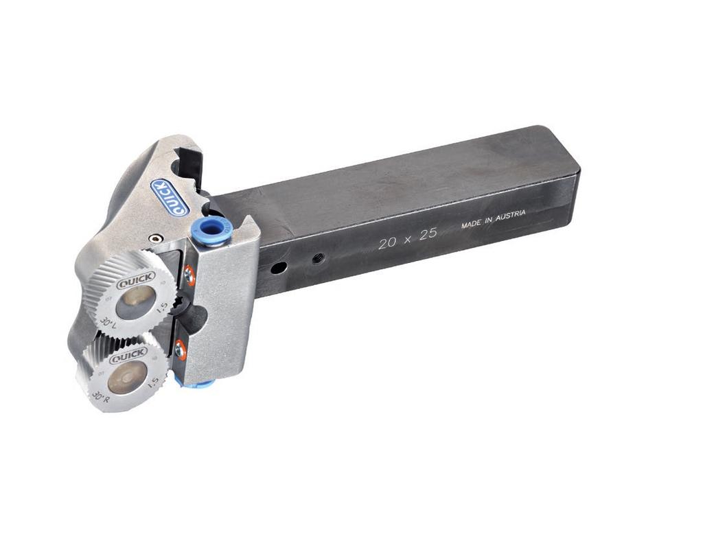
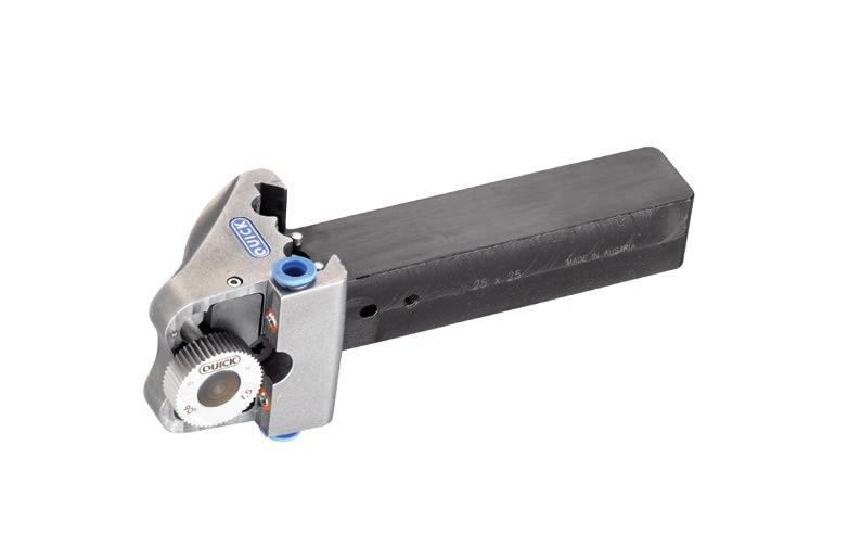
4 1.2 Tool Construction B-series tools are flexible in use and may be employed on all lathes from the conventional to CNC-controlled multiple-spindle lathes, optionally as a left-hand or right-hand tool, in front or behind the turning centre. The tools press the corresponding knurling shape by cold forming on the workpiece, thus providing chipless machining. General Tool Construction It is not possible to make them adopt a specific speed ratio to the diameter of the workpiece by means of sustained forcing. As a result the number of teeth of the knurl produced may differ. The difference is approx. +/- 1-3 teeth depending on the pitch. Type of knurl DIN 82 Tool Knurling wheel Straight knurl RAA B2/FL 90 Spiral knurl RBL / RBR B2/FL As required Cross knurl RKE B2/KF 45 L + 45 R Diamond knurl RGE B2/KF 30 L + 30 R 3
5 General Tool Construction Applications Machining of cold formable materials All knurling shapes and knurling profiles are possible with a single tool Knurling is possible as far as the flange or workpiece shoulder The tool can be applied to any point on the workpiece Tool definition Definition of the tool as left- or right-handed is determined by the position of the knurling wheels when the tool is viewed from the front in the clamped position. left right left right Clamping Clamping of the tool body on the shank is effected by means of an eccentric chuck. The surface clamping generated as a result reduces the vibrations arising due to machining and increases the service life of the knurling wheels. Shanks and bodies may be individually assembled easily and without much effort by the customer himself. 4
6 General Tool Construction Perfect results may be achieved with: Correct adjustment Closely following the instructions regarding the start of the knurling process Appropriate feed and cutting speed NOTE: It is imperative to ensure an abundant supply of coolant or cutting oil directly onto the knurling wheels to ensure perfect cooling and lubrication of the knurling wheels. Supplied with Pos. Description 1 Tool holder with shank 2 Wheel holder (x 2) 3 Washer(x 2) 4 Knurling wheels (as required) 5 Coolant hose 6 Blanking plug 7 Tool key - Torx 25 8 Paste Molykote G 9 Instructions for Use 9 5
7 B2 Tools Technical Data 2. B2 Tools 2.1 Technical Data B2/KF Types of knurl Cross and diamond Working range Ø mm Shank dimension 20x25 or 25x25 mm Knurling wheel Ø 25 mm Cross 1 x 45 L and 1 x 45 R Diamond 1 x 30 L and 1 x 30 R Pitches see page 20 Weight 1.1 kg B2/FL Types of knurl Straight and spiral RAA / RBL / RBR Working range Ø mm Shank dimension 20x25 or 25x25 mm Knurling wheel Ø 25 mm Straight 1 x 90 Spiral As required Pitches see page 20 Weight 1.1 kg 6
8 2.2 Overview: Main components B2 Tools Overview: Main components Pos. Description 1 Tool head 2 Wheel holder with wheel flat 3 Knurling wheel 4 Washer 5 Cover plate 6 Terminal strip 7 Clamping segment 8 Index point 9 Coolant nozzles 10 Shank 11 Eccentric bolt 12 Spindle screw 7
9 B2 Tools Tool adjustment B2/KF 2.3 Tool adjustment B2/KF Preliminary work: Clamp workpiece and turn. Maximum out-of-roundness: 0.03 mm Step 1: Cutter selection Cross knurl: 1x 45 left-hand spiral toothed knurling wheel on wheel holder "L" 1x 45 right-hand spiral toothed knurling wheel on wheel holder "R" Diamond knurl: 1x 30 left-hand spiral toothed knurling wheel on wheel holder "L" 1x 30 right-hand spiral toothed knurling wheel on wheel holder "R" Step 2: Install knurling wheels Clean contact surface 1.1 for washer 4 on cover plate 5 Apply Molykote G paste lightly to wheel holder 2 and washer 4 Loosen clamping segment 7 by turning counterclockwise Insert wheel holder 2 into knurling wheel 3 and slide on washer 4 Align flat 2.1 of wheel holder to clamping strip 6 and insert wheel holder Tighten clamping segment 7 again, causing the terminal strip to lock the wheel holder into position. Check that the knurling wheel is able to turn with no play 8
10 Step 3: Pre-adjust turning centre For centring of the tool, the mark M on the shank must be aligned with the mark on the head. The mark in the middle of the head should be selected for use in conventional machines The outer marks should be selected for use in CNC machines depending on the shaft dimensions. B2 Tools Tool adjustment B2/KF Adjustment: Unscrew eccentric bolt 11 Adjust tool head 1 accordingly by way of spindle screw 12 Clamp eccentric bolt again hand-tight Pos. Use Shank 0 conventional 20/25 a CNC 20 b CNC 25 -a CNC 20 -b CNC 25 Step 4: Clamp tool in tool holder 9
11 B2 Tools Tool adjustment B2/KF Step 5: Adjust turning centre Carefully bring into contact with the workpiece Both cutters must be in contact simultaneously. Precision adjustment is carried out using spindle screw 12 Tighten eccentric bolts 11 hand-tight when alignment is finished Step 6: Adjust knurling wheels Infeed in X-direction Groove knurling: Adjust the tool so that it is axially parallel with the workpiece. X Longitudinal knurling Tool tilt of approx Z X 1-2 Z X Infeed in the x-direction until a sharp knurl pattern occurs on the workpiece. Usually approx. ½ the pitch of the inserted knurling wheels. The material application is usually ½ the pitch. 10
12 Step 7: Start of knurl TIP: Longitudinal knurling The start of the knurl should be in a width no greater than 1.5 mm. With this width, now move the tool to the full depth (X-axis) without interruption. The feed on infeeding should be approx. 0.1 mm. The knurling depth corresponds to the pitch of the knurling cutter being used, e.g. 1.0 mm pitch requires 0.5 mm infeed with reference to the diameter. The infeed is measured from the knurling cutter's point of contact with the workpiece. max 1,5 mm B2 Tools Tool adjustment B2/KF The surface deformation of the workpiece cannot be determined exactly as this is different from material to material. The knurling depth, however, should be sufficient to ensure that the knurl is only just sharp. NOTE: Please ensure that the protection facing on the start of the workpiece can only be applied after knurling has taken place. The coarser the pitch, the smaller the feed. Feed and cutting speed have no effect on the knurl pitch. Z X After an idle time of 2-3 seconds, the workpiece is knurled by using the longitudinal feed. For feed rate values, see table on page 21. Z X Step 8: Knurling NOTE: If the knurl is not accurate or is onesided, then the knurling process may be repeated after correcting the tool. 11
13 B2 Tools Tool adjustment B2/FL 2.4 Tool adjustment B2/FL Preliminary work: Clamp workpiece and turn. Maximum out-of-roundness: 0.03 mm Step 1: Cutter selection Straight knurl RAA: 1x 90 knurling wheel Spiral knurl: Depending on the spiral tilt desired, knurling wheels with spirals of 30, 45 or a special tooth pitch angle must be installed Because of the large number of possible variations it is advisable to consult your dealer and/or the manufacturer. Step 2: Install knurling wheel Clean contact surface 1.1 for washer 4 on cover plate 5 Apply Molykote G paste lightly to wheel holder 2 and washer 4 Loosen clamping segment 7 by turning counterclockwise Insert wheel holder 2 into knurling wheel 3 and slide on washer 4 Align flat 2.1 of wheel holder to clamping strip 6 and insert wheel holder Tighten clamping segment 7 again, causing the terminal strip to lock the wheel holder into position. Check that the knurling wheel is able to turn with no play 12
14 Step 3: Adjust turning centre For centring of the tool, the mark M on the shank must be aligned with the mark on the head. The mark in the middle of the head should be selected for use in conventional machines The outer marks should be selected for use in CNC machines depending on the shaft dimensions. B2 Tools Tool adjustment B2/FL Adjustment: Unscrew eccentric bolt 11 Adjust tool head 1 accordingly by way of spindle screw 12 Clamp eccentric bolt again hand-tight Pos. Use Shank 0 conventional 20/25 a CNC 20 b CNC 25 -a CNC 20 -b CNC 25 Step 4: Clamp tool in tool holder 13
15 B2 Tools Tool adjustment B2/FL Step 5: Adjust knurling wheels Infeed in X-direction Groove knurling: Adjust the tool so that it is axially parallel with the workpiece. X Longitudinal knurling Tool tilt of approx. 1-2 Step 6: Start of knurl TIP: Longitudinal knurling The start of the knurl should be in a width no greater than 1.5 mm. With this width, now move the tool to the full depth (X-axis) without interruption. The feed on infeeding should be approx. 0.1 mm. The knurling depth corresponds to the pitch of the knurling cutter being used, e.g. 1.0 mm pitch requires 0.5 mm infeed with reference to the diameter. The infeed is measured from the knurling cutter's point of contact with the workpiece. max 1,5 mm Z Z Z X 1-2 Infeed in the x-direction until a sharp knurl pattern occurs on the workpiece. Usually approx. ½ the pitch of the inserted knurling wheels. The material application is usually ½ the pitch. Z X X After an idle time of 2-3 seconds, the workpiece is knurled by using the longitudinal feed. For feed rate values, see table on page 21. X 14
16 The surface deformation of the workpiece cannot be determined exactly as this is different from material to material. The knurling depth, however, should be sufficient to ensure that the knurl is only just sharp. Step 7: Knurling B2 Tools Tool adjustment B2/FL NOTE: If the knurl is not accurate or is onesided, then the knurling process may be repeated after correcting the tool. NOTE: Please ensure that the protection facing on the start of the workpiece can only be applied after knurling has taken place. The coarser the pitch, the smaller the feed. Feed and cutting speed have no effect on the knurl pitch. 15
17 Coolant unit General 3. Coolant unit 3.1 General This integrated cooling system enables targeted cooling and lubrication of the knurling wheels and/or workpieces and thus increases the service life of the tools/knurling wheels. Coolant pressure max. 8 bar 3.2 Overview: Main components Pos. Description 1 Coolant unit integrated into the tool head 2 Adjustable nozzles 3 Push-in connection 4 Coolant hose 5 Blanking plug 16
18 3.3 Assembly/Starting up Step 1: Connect coolant supply Clamp tool in tool holder Insert coolant hose 4 into the top push-in connector 3 until it stops Route hose with corresponding bending radius to connection on tool holder, cut to length as necessary and connect On the second coolant connection, insert blanking plug 5 until limit stop is reached Coolant unit Assembly/Starting up Step 2: Activate cooling system Activate the cooling system before commencing knurling ATTENTION: The coolant unit is designed for a max. pressure of 8 bar. Step 4: Precision adjustment of the ball nozzles on coolant unit To ensure optimal cooling for B2 tools, direct the two nozzles at the knurling wheels NOTE: To remove the hose and the blanking plug, push in the push-in connector slightly. 17
19 Wear Parts 4. Wear Parts The fixing elements for the knurling wheels of the QUICK B2-series tools are wear parts and must be replaced frequently. Pos. Description 1 Wheel holder 2 Washer 18
20 Troubleshooting 5. Troubleshooting B2/KF tool Overlapping of the knurl (double knurl) Approach to knurl depth too slow as a result of which too little guidance of knurling wheels in track Look at start of knurl Teeth of knurling wheel knocked off Knurling wheel has been overloaded feed too great, cutting depth too great Unevenly deep knurl track Re-align position of head using spindle Seizing of knurling wheels on wheel holder Reduce cutting speed Use Molykote paste Coolant jet directly onto the knurling wheels B2/FL tool Knurl trailing spirally Look at start of knurl Look at knurling depth Clearance of tool too positive or too negative Teeth of knurling wheel knocked off Knurling wheel has been overloaded feed too great, cutting depth too great Seizing of knurling wheels on wheel holder Reduce cutting speed Use Molykote paste Coolant jet directly onto the knurling wheels 19
21 Dimensions and pitches Available 6. Dimensions and pitches Available Technical Description Material: Powder metallurgy tool steel Heat treatment: Hardened to HRC Designs: ground Order numbers and designation Ident. no. Ø A Ø B C /12 8 Dimensions and pitches C t A B Ø Tooth pitch angle Pitches (t) toothed 0.5 / 0.6 / 0.8 / 1.0 / 1.2 / L / 30 R toothed 0.5 / 0.6 / 0.8 / 1.0 / 1.2 / L / 45 R toothed 0.5 / 0.6 / 0.8 / 1.0 / 1.2 / 1.5 Pos. Description 1 Production date MM/YY 2 Tooth pitch angle 3 Tooth pitch direction R (right) L (left) 4 Tooth pitch 5 Material 6 Tooth tip angle 7 Production process G (ground) / M (milled) 8 Coated with QDUR / TiCN / TIN 20
22 Reference Values for Feeds and Cutting Speeds 7. Reference Values for Feeds and Cutting Speeds Knurling wheel Ø 25 Material V m/min s mm/rev Steel up to 600 N/mm² Steel up to 900 N/mm² Stainless steels Ms Ms Bronze Cast steel
23 QUICK Tooling GmbH Brunnenstraße Aldingen Germany Tel.: Fax: / Edition. Technical details are subject to change. Printing errors excepted. No part of these document may be copied or disclosed for any purposes without the written approval of QUICK Tooling GmbH. All rights reserved.
INSTRUCTIONS FOR USE A1 & A2 KNURLING TOOLS
 INSTRUCTIONS FOR USE A1 & A2 KNURLING TOOLS Contents CONTENTS 1. General... 2 1.1 Introduction... 2 1.2 Tool Construction... 3 2. A1-Tools... 5 2.1 Technical Data... 5 2.2 Overview: Main Components...
INSTRUCTIONS FOR USE LA, MAMMUT & STR KNURLING TOOLS
 INSTRUCTIONS FOR USE LA, MAMMUT & STR KNURLING TOOLS Contents CONTENTS 1. General... 2 1.1 Introduction... 2 1.2 Tool Construction... 3 2. LA-Tool... 5 2.1 Technical Data... 5 2.2 Overview: Main Components...
NEW RÄNDELFRÄSWERKZEUGE KNURLINGTOOLS
 NEW RÄNDELFRÄSWERKZEUGE KNURLINGTOOLS KNURLING TOOLS Swarovski Optik KG Swarovskistraße 70 A-6067 Absam Fon +43 (0)5223 511-0 Fax +43 (0)5223 511-6550 info@quick-tools.at www.quick-tools.at Milled knurls
Our aim is to offer all our customers an optimal level of product benefits, product advice and customer service.
 Knurling Technology The Company 2 The company Hommel + Keller was founded in 1926 by the precision technician Jakob Keller and his business partner Georg Hommel. During the first years of its operation,
PUNCHING DRILLING HEBEN LIFTING CUTTING DEBURRING
 PUNCHING DRILLING LIFTING CUTTING DEBURRING www.alfra.de E-EN E ALFRA Edge-Milling and Deburring Devices Overview KFV KFH 150 Page 7 78 2520 25100 Prism mounting L = 150 / W = 20/40 End mill Ø 45 or straight
zeus KNURLING TECHNOLOGY --> KNURLING WHEELS --> FORM KNURLING TOOLS --> CUT KNURLING TOOLS --> SPECIAL TOOLS
 zeus KNURLING TECHNOLOGY --> KNURLING WHEELS --> FORM KNURLING TOOLS --> CUT KNURLING TOOLS --> SPECIAL TOOLS TECHNOLOGY. SERVICE. PASSION. WELCOME TO HOMMEL+KELLER PRÄZISIONSWERKZEUGE! We work with enthusiasm
Operating instruction for the quick-change tap holders type:
 type: KSN 0 KSN 1 KSN 3 KSN 4 KSN 5 Date of edition: 01.02.2008 Stage of alteration: 1 Please keep this for future use! Contents: 1 Application range, safety instructions and technical data... 3 1.1 Application
A very warm welcome (Arial, 24-point bold font) Discover what's under the surface (Arial, 20-point bold font in italics)
 Discover what's under the surface (Arial, 20-point bold font in italics)") A very warm welcome (Arial, 24-point bold font) Discover what's under the surface (Arial, 20-point bold font in italics) HORN Technology Days 2015 Longitudinal turning Flexibly producing complex turned
A very warm welcome (Arial, 24-point bold font) Discover what's under the surface (Arial, 20-point bold font in italics) HORN Technology Days 2015 Longitudinal turning Flexibly producing complex turned
March weeks. surcharge for
 March weeks valid until 31.03.2012 all quoted prices are incl. 19% VAT for deliveries in the EU countries to customers with a valid VAT-no. and for deliveries in not EU member countries the VAT is not
Diamond Burnishing Tools
 Diamond Burnishing Tools www.cogsdill.co.uk Diamond burnishing Overview The Cogsdill Diamond Burnishing Tool is designed to produce high quality, low microinch burnished finishes on shafts, large bores,
The new generation with system accessories. Made in Germany!
 1 The new generation with system accessories. Made in Germany! For face, longitudinal and taper turning, thread-cutting. For machining steel, brass, aluminium and plastic. Mounting flange for fastening
The new generation with system accessories. Made in Europe!
 1 The new generation with system accessories. Made in Europe! Of cast iron, wide-legged prismatic guide. For vibration-free work even at high loads. Rear flange for mounting the mill/drill head PF 230.
Precision made in Germany. As per DIN The heart of a system, versatile and expandable.
 1 Precision made in Germany. As per DIN 8606. The heart of a system, versatile and expandable. Main switch with auto-start protection and emergency off. Precision lathe chuck as per DIN 6386 (Ø 100mm).
Operating Manual. for CUTTING, PERFORATING, BENDING SLB120
 Operating Manual for CUTTING, PERFORATING, BENDING SLB120 31040\B06eng 0896 0 Contents 1. Scope of delivery... 1 2. Technical specifications... 1 3. Applications... 1 4. Commissioning... 2 5. Cutting...
Typical Parts Made with These Processes
 Turning Typical Parts Made with These Processes Machine Components Engine Blocks and Heads Parts with Complex Shapes Parts with Close Tolerances Externally and Internally Threaded Parts Products and Parts
Competence Gun Boring. KOYEMANN Floating Tools Power Reamer
 Competence Gun Boring KOYEMANN Floating Tools Power Reamer R The KOYEMANN Floating Principle Reaming has been used for fine machining bores with excellent results from the very start of cutting technology.
User s Guide. Silent Tools. turning products
 User s Guide Silent Tools turning products Introduction This guide will help you to use dampened boring bars (Silent Tools) to achieve the best possible results in internal turning. Silent Tools dampened
no mm no Dividers with scriber 150 mm NEW Square wedge-shaped knife edges on the length side
 Summer Promotion valid until 30.06.2013 all quoted prices are incl. VAT for deliveries to EU countries to customers with valid VAT-no. and for deliveries in non EU member countries the VAT is not applicable
Lathe is a machine, which removes the metal from a piece of work to the required shape & size HENRY MAUDSLAY
 TURNING MACHINES LATHE Introduction Lathe is a machine, which removes the metal from a piece of work to the required shape & size HENRY MAUDSLAY - 1797 Types of Lathe Engine Lathe The most common form
Technical T-A & GEN2 T-A GEN3SYS APX. Revolution & Core Drill. ASC 320 Solid Carbide. AccuPort 432. Page CONTENTS. Set-up Instructions 256
 Technical ASC 0 Solid Carbide CONTENTS Page Set-up Instructions 6 AccuPort 4 Recommended Speeds & Feeds 60 Guaranteed Application Request Form 99 +44 (0)84 400 900 +44 (0)84 400 0 enquiries@alliedmaxcut.com
Special reamers. Figure N 1 Reamer with descending cutting edges in carbide (Cerin)
") Special reamers There is a wide category of special reamers, ie non-standard, that are suitable to address particular problems encountered in the finishing holes, both for maintenance of individual pieces
Special reamers There is a wide category of special reamers, ie non-standard, that are suitable to address particular problems encountered in the finishing holes, both for maintenance of individual pieces
Tool & Cutter Grinder
 Tool & Cutter Grinder The Bonelle Tool and Cutter grinder (based on prof. Chaddock s Quorn) can be used to grind most kind of tools from lathe tools to end-mills and reamers. I have been grinding my end-mills
-Eagle Edger Jr Linear Edge Add-on for the Blue Ripper Jr
 -Eagle Edger Jr Linear Edge Add-on for the Blue Ripper Jr (Blade shown might not ship with tool, or be available.) Operation, Safety, and Instruction Manual v20150521 Page 2 Operating/Safety Instructions
Machining. Module 6: Lathe Setup and Operations. (Part 2) Curriculum Development Unit PREPARED BY. August 2013
 Curriculum Development Unit PREPARED BY. August 2013") Machining Module 6: Lathe Setup and Operations (Part 2) PREPARED BY Curriculum Development Unit August 2013 Applied Technology High Schools, 2013 Module 6: Lathe Setup and Operations (Part 2) Module Objectives
Machining Module 6: Lathe Setup and Operations (Part 2) PREPARED BY Curriculum Development Unit August 2013 Applied Technology High Schools, 2013 Module 6: Lathe Setup and Operations (Part 2) Module Objectives
Screws. Introduction. 1. Nuts, bolts and screws used to clamp things together. Screws are used for two purposes:
 Screws Introduction Screws are used for two purposes: 1. To clamp things together. 2. To control motion. 1. Nuts, bolts and screws used to clamp things together. Nuts, bolts and screws that are used for
KPSM contour. grinding. KPSM Type For grinding of longitudinal profile up to 70 x 70 mm Flat grinding up to 600 mm width
 KPSM contour precision grinding machine KPSM Type 2200-4200 For grinding of longitudinal profile up to 70 x 70 mm Flat grinding up to 600 mm width KPSM-SerieS Benefits Highly rigid construction The rigid
Clamping devices 521
 Clamping devices 521 522 Product overview Clamping devices Adjustable straps K0001 Hook clamps K0012 Goose-neck straps with long slot K0002 Page 526 Hook Clamps with collar K0013 Page 535 Equipped clamps
Workpiece Clamping. Collets for Workpiece Clamping Collet Chucks for Workpiece Clamping
 Workpiece Clamping Collets for Workpiece Clamping Collet Chucks for Workpiece Clamping Overview of Contents Page Collets for Workpiece Clamping Draw-in Collets DI 2 Dead Length Collets DL 3 Emergency Dead
TURNING BORING TURNING:
 TURNING BORING TURNING: FACING: Machining external cylindrical and conical surfaces. Work spins and the single cutting tool does the cutting. Done in Lathe. Single point tool, longitudinal feed. Single
CNC milling machines. Pocket milling. Milling of segments into a drive wheel. Milling of the outer contour
 CNC milling machines You want to mill with precision! WABECO CNC milling machines guarantee you the ultimate precision covering the entire working range of the machine. Production in Germany on state-of-the-art
EMCOMAT E-200 MC for the m cycle-controlled m
 EMCOMAT E-200 MC for the m cycle-controlled m 1 HEADSTOCK Solid cast-iron construction Powerful Siemens drive system Short taper spindle nose with CAMLOCK adaptor Spindle bore diameter ø 53 (50) mm 2 2
SERVICE INSTRUCTIONS :
 1 HAROLD HABEGGER SA TÉL. ++41 32 497 97 55 INTERNET: www.habegger-sa.com FABRIQUE DE MACHINES FAX ++41 32 497 93 08 E-MAIL: contact@habegger-sa.com OUTILLAGE ROUTE DE CHALUET 5/9 CH-2738 COURT (SUISSE)
5-axis clamping system compact
 5-axis clamping system compact 395 5-axis clamping system compact Function We are setting standards with the new KIPP 5-axis clamping system compact in this field. The system was specifically designed
OPERATING INSTRUCTIONS 5-AXIS CLAMPING SYSTEM + ACCESSORIES
 OPERATING INSTRUCTIONS 5-AXIS CLAMPING SYSTEM + ACCESSORIES 1 Contents 1. Introduction 2. Safety instructions and precautions 3 Operating the clamp 3.1 Clamp set up 3.2 Sequence for clamp set up 3.3 Adjusting
Maier ML20D - Technical Details. for illustration purposes only. Maier CNC Swiss Type Lathe ML20D ProLine
 Maier ML20D - Technical Details for illustration purposes only Maier CNC Swiss Type Lathe ML20D ProLine Machine concept & construction The machine base of all the Maier ProLine CNC Sliding Headstock Machines
ENGINE REBUILDING MACHINES
 ENGINE REBUILDING MACHINES Zylinderbohrwerke: Typ MA Typ SIRIO Typ SPES Typ ORION Typ OLYMPIA 19 MA OLIMPIA ORION SPES SIRIO 20 Automatic emergency stop system. Total shutdown in case of accidental impact
Vertical and horizontal Turning/Grinding Centers
 Vertical and horizontal Turning/Grinding Centers INDEX Turning/Grinding Centers Turning and grinding of course with INDEX The INDEX Turning/Grinding Centers combine the advantages of turning and grinding
in perfect order Gripping under pressure Cleaning Unit rgg for your machine room Manufacturing more efficiently!
 in perfect order Gripping under pressure Cleaning Unit rgg for your machine room Vacuum gripper solves your time and cost goals Vacuum functionality can be implemented without an additional vacuum connection
Compatibility overview of accessories for lathe
 Compatibility overview of accessories for lathe Accessory parts for turning Face clamping disc Ø 170 mm 3440295 Face clamping disc Ø 240 mm 3441352 Face clamping disc Ø 250 mm 3440552 Face clamping disc
AUTOMATION ACCESSORIES
 RG SERIES AUTOMATION ACCESSORIES The Vision System Faster than contact probes, the ultra-highspeed vision system gives integrated, closed loop control of the machine using the image from the camera. The
SAFETY INSTRUCTIONS. Wear protective clothing, including safety glasses and steel toe boots.
 SAFETY INSTRUCTIONS Wear protective clothing, including safety glasses and steel toe boots. DO NOT allow loose clothing or long hair near machine operations. Keep work site and machine clean. Use brush
Features. Special forms are possible
 Center Drill >> The is a trademark of Nine9, the developer of the first indexable center drill in the world.(patented) Offering an indexable insert system for the 1st time, Nine9 s design improves your
Think efficiency, Think HSS MILLING
 Think efficiency, Think HSS MILLING SUMMARY MILLING TOOLS 2 Zoom on a milling cutter 3 Which HSS for maximum efficiency? 4 Coatings for the best performance 5 Vocabulary 6 Choose the right design 7 Select
WSG 8-115; 8-125; P; WSG ; WSG P; WSG PS; WSG P; WSG 15-70Inox
 Repair instructions Page of 47 Contents. Models described 2. Technical data 3. Notes and requirements 4. Tools required 5. Lubricants and auxiliary substances required 6. Disassembly 7. Assembly 8. Connection
Quick Set Dovetail Jig
 Quick Set Dovetail Jig FOR HELP OR ADVISE ON THIS PRODUCT PLEASE CALL OUR CUSTOMER SERVICE HELP LINE : 01509 500359 THE MANUFACTURER RESERVES THE RIGHT TO ALTER THE DESIGN OR SPECIFICATION TO THIS PRODUCT
Various other types of drilling machines are available for specialized jobs. These may be portable, bench type, multiple spindle, gang, multiple
 Drilling The process of making holes is known as drilling and generally drilling machines are used to produce the holes. Drilling is an extensively used process by which blind or though holes are originated
MINI-LATHE QUICK CHANGE TOOL POST
 MINI-LATHE QUICK CHANGE TOOL POST Cutting and assembly details Machinists should familiarize themselves with the contents of this section before jumping in to the drawings. Many details are described here
192 Series Precision Involute Knurl / Spline Tools. Instruction Manual
 192 Series Precision Involute Knurl / Spline Tools Instruction Manual Table of Contents Introduction... 3 What is an Involute Knurl or Spline?... 3 Why Roll Involute Knurl Connections?... 3 Why Use a CJWinter
JARVIS. Model BR-3 Blade Reconditioner ... EQUIPMENT TABLE OF
 - Model BR-3 Blade Reconditioner EQUIPMENT SELECTION.......... Ordering No. TABLE OF CONTENTS............................ Page Model BR-3 (100 mm Blade) 115V/60Hz............ 4011003 220V/50Hz............
Machining Strenx and Hardox. Drilling, countersinking, tapping, turning and milling
 Machining and Drilling, countersinking, tapping, turning and milling and are registered trademarks. These steel grades are manufactured only by SSAB. high strength steel and wear plate are steel grades
The new generation with system accessories. Made in Germany!
 1 The new generation with system accessories. Made in Germany! For face, longitudinal and taper turning, thread-cutting. For machining steel, brass, aluminium and plastic. Mounting flange for fastening
BSF. Large Ratio Automatic Back Counterboring & Spotfacing Tool
 BSF Large Ratio Automatic Back Counterboring & Spotfacing Tool Counterbores up to 2.3xd Replaceable carbide coated blades for extended life Very simple to use Suitable for CNC machines with through coolant
ROTARY TABLE OPERATION AND SERVICE MANUAL HORIZONTAL AND VERTICAL. Horizontal & Vertical. Rotary Table (HVRT) Tilting Rotary Table
 Tilting Rotary Table") Horizontal & Vertical Rotary Table (HVRT) OPERATION AND SERVICE MANUAL Tilting Rotary Table Horizontal & Vertical Rapid Indexer VERTICAL AND HORIZONTAL ROTARY TABLE This Horizontal & vertical table is
Horizontal & Vertical Rotary Table (HVRT) OPERATION AND SERVICE MANUAL Tilting Rotary Table Horizontal & Vertical Rapid Indexer VERTICAL AND HORIZONTAL ROTARY TABLE This Horizontal & vertical table is
TOOLS/PROCESSING SERVICES TOOLS + PROCESSING SERVICES
 TOOLS/PROCESSING SERVICES 7 TOOLS + PROCESSING SERVICES MINITEC PROFILE SYSTEM 583 TOOLS/PROCESSING SERVICES TOOLS s l oot TOOLS 584 MINITEC PROFILE SYSTEM BALL-HEADED KEY - Chrome plated, with handle
VARIABLE SPEED WOOD LATHE
 MODEL MC1100B VARIABLE SPEED WOOD LATHE INSTRUCTION MANUAL Please read and fully understand the instructions in this manual before operation. Keep this manual safe for future reference. Version: 2015.02.02
Lathe Accessories. Work-holding, -supporting, and driving devices
 46-1 Lathe Accessories Divided into two categories Work-holding, -supporting, and driving devices Lathe centers, chucks, faceplates Mandrels, steady and follower rests Lathe dogs, drive plates Cutting-tool-holding
ALFRA. Deburring Technology. Bevel Milling and Deburring Devices for the universal use B/79
 ALFRA B Deburring Technology Bevel Milling and Deburring Devices for the universal use B/79 ALFRA Bevel Milling and Deburring Devices Overview Made in Germany by ALFRA Page B/84 Page B/86 Type KFV KFH
Adjusting Backlash on Sherline handwheels
 WEAR YOUR SAFETY GLASSES FORESIGHT IS BETTER THAN NO SIGHT READ INSTRUCTIONS BEFORE OPERATING Adjusting Backlash on Sherline handwheels What Is Backlash? Backlash is the amount the handwheel can turn before
GMR 1 PROFESSIONAL. ÁU~²Ýœ ÈULM¼« Àπ ß Õ ŸË Õ Èß π Petunjuk-Petunjuk untuk Penggunaan HıÎng dõn s dùng Instructions d emploi. Operating Instructions
 609 40 44 - Buch Seite Dienstag,. Juni 004 :5 5 GMR PROFESSIONAL * Des idées en action. Operating Instructions Àπ ß Õ ŸË Õ Èß π Petunjuk-Petunjuk untuk Penggunaan HıÎng dõn s dùng Instructions d emploi
Operating Instructions. Universal drilling and milling machines with linear guideways
 Operating Instructions Universal drilling and milling machines with linear guideways F1410 LF F1410 LF high speed CC-F1410 LF CC-F1410 LF high speed Walter Blombach GmbH Tool and Machine Factory D-42899
MODEL 7000 BEVEL-MILL
 MODEL 7000 BEVEL-MILL HECK INDUSTRIES P.O. BOX 425 HARTLAND, MI 48353 TOLL FREE: 800-886-5418 PHONE: 810-632-5400 FAX: 810-632-6640 WWW.HECKIND.NET INSTRUCTION MANUAL Save This Manual You will need the
MANUFACTURING TECHNOLOGY
 MANUFACTURING TECHNOLOGY UNIT V Machine Tools Milling cutters Classification of milling cutters according to their design HSS cutters: Many cutters like end mills, slitting cutters, slab cutters, angular
Servoturn 410. Servoturn 410. Lathe. Conventional Precision Lathe with servo drive.
 Lathe Conventional Precision Lathe with servo drive easy to operate, more reliable, more precise, for higher loads and reduced maintenance Mineral-Casting Machine Frame preloaded ball screws electronic
Operating instructions. Fine boring head Ø3-88 with digital display
 Operating instructions Fine boring head Ø3-88 with digital display English 1. Basic safety information Before first use, please read the operating instructions carefully. These provide important safety
ROOP LAL Unit-6 Lathe (Turning) Mechanical Engineering Department
 Mechanical Engineering Department") Notes: Lathe (Turning) Basic Mechanical Engineering (Part B) 1 Introduction: In previous Lecture 2, we have seen that with the help of forging and casting processes, we can manufacture machine parts of
Notes: Lathe (Turning) Basic Mechanical Engineering (Part B) 1 Introduction: In previous Lecture 2, we have seen that with the help of forging and casting processes, we can manufacture machine parts of
Hardinge FlexC Dead-Length Collet System Style DL 42mm. Installation Instructions and Parts Lists
 Hardinge FlexC Dead-Length Collet System Style DL 42mm Installation Instructions and Parts Lists 1 General Safety Information Before installing the Hardinge FlexC Collet System on your machine tool, thoroughly
V-Turn 410. V-Turn 410. CNC Precision Lathes. incl. 3-axis position indicator and integrated spindle speed indicator, completely assembled
 CNC Precision Lathes incl. 3-axis position indicator and integrated spindle speed indicator, completely assembled center width 1000 / 1500 mm max. turning diameter over bed 410 mm infinitely variable spindle
OPERATING INSTRUCTIONS MODULGRAV. Tel. +49 (0) Fax +49 (0) homepage:
 Fax +49 (0) homepage:") OPERATING INSTRUCTIONS MODULGRAV Kolpingstraße -7 D-784 Singen / Htwl. Postfach 80 D-784 Singen / Htwl. Tel. +49 (0) 77 88-0 Fax +49 (0) 77 88 66 e-mail: info@elma-ultrasonic.com homepage: www.elma-ultrasonic.com
OPERATING INSTRUCTIONS MODULGRAV Kolpingstraße -7 D-784 Singen / Htwl. Postfach 80 D-784 Singen / Htwl. Tel. +49 (0) 77 88-0 Fax +49 (0) 77 88 66 e-mail: info@elma-ultrasonic.com homepage: www.elma-ultrasonic.com
3 Emergency Breakaway Coupling
 SM64227 July 2008 Applicable addition manuals: N/A Aerospace Group Conveyance Systems Division Carter Ground Fueling Maintenance & Repair Manual 3 Emergency Breakaway Coupling Model 64227 Table of Contents
400 SERIES GRINDER PUMPS 41502, 42202,43302, AND MODELS
 Section: MOYNO 500 PUMPS Page: 1 of 6 Date: March 1, 1998 SERVICE MANUAL MOYNO 500 PUMPS 400 SERIES GRINDER PUMPS 41502, 42202,43302, AND 44402 MODELS DESIGN FEATURES Housing: Cast iron Pump Rotor: Chrome
Horizontal and Vertical. Metal Cutting Band Saw MODEL: BS-115
 Horizontal and Vertical Metal Cutting Band Saw MODEL: BS-5 SAFETY. Know your band saw. Read the operator s Manual carefully. Learn the operations, applications and limitation.. Use recommended accessories.
DRA DRA. MagicDrill. High Efficiency Modular Drill. Excellent hole accuracy with a low cutting force design. High Efficiency Modular Drill
 High Efficiency Modular Drill High Efficiency Modular Drill MagicDrill DRA Excellent hole accuracy with a low cutting force design Optimal web thickness limits deflection Fine chip breaking and smooth
Cutting Off Saw. Model:TV-350. Operation Manual
 Cutting Off Saw Model:TV-350 Operation Manual 1 Table of content 1. Introduction..3 1.1 General...3 1.2 Safety regulations.3 1.3 Guarantee.. 4 2. Technical data.. 4 2.1 Main groups...4 2.2 Survey and sketch
Machining. Drilling Countersinking Tapping Turning Milling
 Machining Drilling Countersinking Tapping Turning Milling hardox and weldox are registered trademarks.these steel grades are manufactured only by SSAB Oxelösund AB. hardox wear plate and weldox extra-high
FORM HOLDING CLAMPS 8. 1 FORM HOLDING CLAMPS JAWS MOUNTING-ON-LATHE ADAPTERS. FORM HOLDING CLAMPS Wedge Style/Round
 pag..4 JAWS pag..6 MOUNTING-ON-LATHE ADAPTERS pag..7 Wedge Style/Round pag.. Wedge Style/Square pag..10 pag..12 JAWS for external Form Holding pag..14 JAWS for internal Form Holding pag..16 TAPERED SCREWS
Servomill. Multipurpose Milling Machine Servomill. Conventional Multipurpose Milling Machine.
 Multipurpose Milling Machine Conventional Multipurpose Milling Machine for workshop applications, single parts production and training purposes Servo motors and preloaded ball screws on all axes infinitely
Indexable Center Drill
 i-center indexable center drill (patent pending) First Indexable center drill in the world. Shortens set up time and center drilling time. Increases tool life which reduces tooling cost. Special forms
DRILL GRINDING ATTACHMENT
 DRILL GRINDING ATTACHMENT To suit TM6025Q TOOL AND CUTTER GRINDER OPERATION S MANUAL 1 0º 270º 90º 180º INTRODUCTION Before grinding any cutters, you must set up the attachment to suit the type of cutter
STARTING SERIAL NUMBER PARTS LIST FOR. Wellsaw MODEL 600 METAL CUTTING BAND SAW
 STARTING SERIAL NUMBER 11075 PARTS LIST FOR Wellsaw MODEL 600 METAL CUTTING BAND SAW Wellsaw 2829 N. Burdick, Kalamazoo, MI 49004 Phone: 269-345-1132 Fax: 269-345-0095 Rev 171005 INSTALLATION, OPERATION
Instruction Manual X97
 Index Page Technical data... 2 Dimensions... 3 General description... 4 Selection of cutter... 5 Instruction for grinding... 5 Dimensions of bevel... 7 Bevelling angle... 8 Adjustment: Straight edge (Land)...
High-precision inch guide units Made in Germany
 High-precision inch guide units Made in Germany cm 1 2 3 4 5 6 7 8 9 10 11 12 13 14 15 16 17 18 19 20 cm inch inch 1 2 3 4 5 6 7 8 STEINEL All you need for tools Your partner for punching and bending
Top spin Nr /
 Top spin Nr. 1840 0000 / 1840 1000 Bedienungsanleitung 21-6680 28052014 / A Made in Germany Ideas for dental technology Top spin Nr. 1840 0000 / 1840 1000 Contents 1. Introduction...2 1.1 Symbols...2 2.
MATEC 30 HV KISTNER GmbH & Co. KG. Industriestraße 7-9 D Thurnau Tel. (+49)
") MATEC 30 HV 2000 KISTNER GmbH & Co. KG Industriestraße 7-9 D-95349 Thurnau Tel. (+49) 9228 987-0 info@maschinen-kistner.de www.maschinen-kistner.de MACHINE INFO Manufacturer Type Year of manufacture Control
MATEC 30 HV 2000 KISTNER GmbH & Co. KG Industriestraße 7-9 D-95349 Thurnau Tel. (+49) 9228 987-0 info@maschinen-kistner.de www.maschinen-kistner.de MACHINE INFO Manufacturer Type Year of manufacture Control
Shaft coupling: compensation of mismatching shaft ends (see page B 117) Flange bearing: linear drive bearing (see page B 96)
 Flange bearing: linear drive bearing (see page B 96)") Overview Linear Drives At the employment of linear drives, the directly or via a toothed belt driven spindle is the most frequently applied variant. Motor flange bearing End flange bearing (two angular
Overview Linear Drives At the employment of linear drives, the directly or via a toothed belt driven spindle is the most frequently applied variant. Motor flange bearing End flange bearing (two angular
FMT 250; FMT 250Q; FMT 250QSL. Repair instructions FMT 250Q / FMT 250QSL. Page 1 of 30
 Repair instructions FMT 250 FMT 250Q / FMT 250QSL Page 1 of 30 Contents 1. Models described 2. Technical data 3. Notes and requirements 4. Tools required 5. Lubricants and auxiliary substances required
STAMPING TECHNOLOGY - CLAMPING RAW PARTS
 simple. gripping. future. 5-Axis 66 Makro Grip Stamping Unit 72 Stamping Unit for the workbench 73 Stamping Unit on trolley 76 Stamping Unit Accessories 77 Stamping Jaws 78 Makro Grip 5-Axis-Vices 82 5-Axis
and AM-CAT-COREV(GB)-11/08 High Performance Indexable Insert Systems
-11/08 High Performance Indexable Insert Systems") and AM-CAT-COREV(GB)-11/08 High Performance Indexable Insert Systems Allied Maxcut Engineering Co. Limited AMEC Indexable Drill Range The AMEC range of adjustable indexable carbide drills provides the
and AM-CAT-COREV(GB)-11/08 High Performance Indexable Insert Systems Allied Maxcut Engineering Co. Limited AMEC Indexable Drill Range The AMEC range of adjustable indexable carbide drills provides the
THREAD CUTTING & FORMING
 THREAD CUTTING & FORMING Threading, Thread Cutting and Thread Rolling: Machining Threads on External Diameters (shafts) Tapping: Machining Threads on Internal Diameters (holes) Size: Watch to 10 shafts
Assembly instructions
 Assembly instructions Important notes on VOSS assembly instructions In order to ensure maximum performance and functional reliability of VOSS products, the respective assembly instructions, operating conditions
Welding & Fabrication Tools FT-Flat Electrode Welding
 Welding & Fabrication Tools FT-Flat Electrode Welding Instruction Manual The Next Step in Belting Welding & Fabrication FT-Flat Electrode Welding Table of Contents Page How to Use this Manual 3 Symbols
52/8 04/2005 UNIVERSAL. Narrow Stitching Head. Operating-Instructions Spare parts list
 Operating-Instructions Spare parts list UNIVERSAL 52/8 04/2005 Narrow Stitching Head hohner Maschinenbau GmbH Gänsäcker 19, 78532 Tuttlingen, Telephone 07462 / 9468-0, Fax 07462 / 9468-20 hohner Maschinenbau
TOP WORK ISO 9001.CE UNIVERSAL CUTTER & TOOL GRINDER
 TOP WORK ISO 9001.CE UNIVERSAL CUTTER Precise ball groove of conformation Inclination of Wheelhead The wheelhead can easily tilt up to ±15 degrees, with a 360-degrees swivel on the horizontal plane. The
CLAMPING TECHNOLOGY Individual special clamping tools
 CLAMPING TECHNOLOGY Individual special clamping tools 1 QUALITY SINCE 1958 Know-how, the highest quality and first class engineering. We see ourselves as a system supplier and offer our customers a full
Operating instructions. Twin cutter boring head Ø mm
 Operating instructions Twin cutter boring head Ø23.5-153.0 mm English 1. Basic safety information Before first use, please read the operating instructions carefully. These provide important safety information
Back-Spotfacing. Flipcut For back-spotfacing and backor front-chamfering operations from one side, in one set-up. Back-Spotfacing. & Chamfering TOOLS
 COGSDILL TOOL PRODUCTS, INC. Flipcut For back-spotfacing and backor front-chamfering operations from one side, in one set-up. Back-Spotfacing & Chamfering TOOLS Back-Spotfacing Available from stock for
Operating instruction for the quick-change adapters type:
 type: EM 00 - U EM 01 - U EM 03 - U EM 04 - U EM 05 - U EM 01 U / IKZ EM 03 U / IKZ EM 04 U / IKZ EM 05 U / IKZ Date of edition: 01.02.2008 Stage of alteration: 2 Please keep this for future use! Contents:
Compatibility overview of accessories for lathe
 Compatibility overview of accessories for lathe Accessory parts for turning TU 1503 TU 2004 TU 2304 TU 2404 TU 2506 TU 2807 D 320 TU 3209 D 330 D 360 TU 3610V TZ 4012 D 420 TU 4210V D 460 TU 4615V TZ 5216
Operator's manual. TruTool N 1000 (1B1) english
 english") Operator's manual TruTool N 1000 (1B1) english Table of contents 1. Safety...4 1.1 General safety information...4 1.2 Specific safety information...5 2. Description...6 2.1 Intended use...7 2.2 Technical
Operator's manual TruTool N 1000 (1B1) english Table of contents 1. Safety...4 1.1 General safety information...4 1.2 Specific safety information...5 2. Description...6 2.1 Intended use...7 2.2 Technical
ISH-R150 MANUAL ROCKWELL HARDNESS TESTER OPERATION MANUAL
 MN-ISH-R15-E www.insize.com ISH-R15 MANUAL ROCKWELL HARDNESS TESTER OPERATION MANUAL Attention Description This Instruction Manual shall be carefully read through in prior to use of the apparatus to clearly
Ball screw spindles are roll manufactured using modern machines prior to hardening and polishing.
 Functional overview Ball screw spindle Ø 16 Ball screw spindle Ø 25 Overview 2-45 2-46 2-46 Ball screw nut 2 2-47 Ball screw nut 3 2-47 Clamping blocks for nut version 3 2-48 for spindle Ø 16 2-49 for