Tools for the Mechanical Mounting and Dismounting of Rolling Bearings
|
|
|
- Caitlin Turner
- 5 years ago
- Views:
Transcription

1 Tools for the Mechanical Mounting and Dismounting of Rolling Bearings
2
3 Contents Page Mechanical mounting and dismounting of rolling bearings... 2 Cylindrical bearing seats... 2 Tapered bearing seats... 3 Tools for mounting... 5 Mounting tool set FITTING-TOOL-ALU Tools for mounting and dismounting Sockets LOCKNUT-SOCKET Hook wrenches LOCKNUT-HOOK Jointed hook wrenches LOCKNUT-FLEXIHOOK Jointed pin wrenches LOCKNUT-FLEXIPIN Double hook wrenches LOCKNUT-DOUBLEHOOK Tools for dismounting Two-arm extractors PULLER-2ARM Two-arm separator extractors PULLER-2ARM-SEPARATOR Three-arm extractors PULLER-3ARM Hydraulic pressure tool PULLER-SUPPORT Hydraulic extractors PULLER-HYD Three-section extraction plates PULLER-TRISECTION Internal extractors PULLER-BORE Internal extractors PULLER-INTERNAL SET Special bearing extractors PULLER-SPECIAL Schaeffler Technologies TPI 216 1

4 Mechanical mounting and dismounting of rolling bearings Cylindrical bearing seats Mounting In order to prevent bearing damage, the mounting forces must always be applied to the tightly fitted ring during mounting and dismounting. If the extraction forces are directed through the rolling elements during extraction of rolling bearings, the bearings are generally rendered unusable. Smaller bearings can be driven cold onto the shaft or into the housing for normal tight fits. For the economical and secure mounting of rolling bearings in the range up to 50 mm bore diameter and up to 110 mm outside diameter, mounting tool sets are suitable. They can also be used to easily mount sleeves, intermediate rings, seals and similar components, Figure 1. Tightly fitted inner rings can be driven onto the shaft or outer rings can be driven into the housing bore by hitting a mounting sleeve with the hammer. Applying the mounting force to the tightly fitted bearing ring prevents the mounting forces from being transmitted through the rolling elements and raceways, which can lead to damage. The precision parts are matched to each other, ensuring that the forces are uniformly transmitted to the side faces of the bearing rings CF Figure 1 Mounting tool set Dismounting Extraction tools are used for dismounting. Particular care is also necessary during dismounting in order to prevent damage to the bearing. The extraction tool must always be applied to the ring to be removed. For the dismounting of small bearings up to approx. 100 mm bore diameter that are located with a tight fit on the shaft or in the housing, mechanical extractors are used. The extraction force is normally applied by means of a threaded spindle, Figure 2. In the case of extractors for larger rolling bearings, the work can be aided by means of a hydraulic spindle. In this way, extraction forces of up to 400 kn (40 tonnes) can be generated. 2 TPI 216 Schaeffler Technologies


5 Figure 2 Two-arm extractor Tapered bearing seats The inner ring of a bearing with a tapered bore is always mounted with a tight fit. The bearing can be seated directly on a tapered shaft or be located on a cylindrical shaft using an adapter sleeve or withdrawal sleeve. When the inner ring is pushed on, it is expanded and the radial internal clearance of the bearing is reduced. The reduction in radial internal clearance is thus an indication of the seating of the inner ring. In order to prevent bearing damage, the inner ring must not be pushed on too far. As an alternative to measurement of the radial internal clearance, the axial drive-up distance can also be measured in order to set the radial internal clearance correctly. Locknuts can be easily tightened and loosened on shafts, adapter sleeves and withdrawal sleeves using sockets. Hook wrenches can be used to tighten and loosen locknuts and precision locknuts on shafts, adapter sleeves or withdrawal sleeves, Figure 3. If no tightening torque is specified, jointed hook wrenches and jointed pin wrenches can be used for locknuts and precision locknuts. 0001AA2D 00097B14 Figure 3 Hook wrench Schaeffler Technologies TPI 216 3

6 Mechanical mounting and dismounting of rolling bearings Double hook wrenches are engraved with a torsional angle scale. The radial internal clearance can thus can be set precisely for selfaligning ball bearings and spherical roller bearings without the need for measurement, Figure 4. Figure 4 Double hook wrench FAG MOUNTING MANAGER Further information The online calculation program MOUNTING MANAGER is a userfriendly aid for ensuring the correct mounting of bearings with a tapered bore. It shows suitable mounting methods, calculates the data required for mounting in relation to the reduction in radial internal clearance and drive-up distance and generates a list of the accessories and tools required. Guide values for the reduction in radial internal clearance: Mounting Handbook MH 1, Mounting of Rolling Bearings Feeler gauges for measuring the radial internal clearance of rolling bearings: Catalogue IS 1, Mounting and Maintenance of Rolling Bearings Online calculation program FAG MOUNTING MANAGER: B 4 TPI 216 Schaeffler Technologies

7 Tools for mounting Mounting tool set

8 Mounting tool set FITTING-TOOL-ALU Features The mounting tool set FITTING-TOOL-ALU facilitates particularly economical mounting of many standardised rolling bearings and other parts with a cylindrical bore. It is suitable for rolling bearings with a bore diameter of 10 mm to 50 mm. Each mounting sleeve can be pushed over the shaft end by up to 220 mm. The mounting rings are made from impact-resistant plastic. This prevents metal/metal contact as well as damage to or premature wear of the bearing seats. The mounting sleeves are made from aluminium. The head of the recoilless hammer produces no sparks. The low mass of the components makes this mounting tool set very easy to handle. The parts are driven into place by hitting the mounting sleeve with the hammer, Figure 1. Figure 1 FITTING-TOOL-ALU 0001A485 The combination of mounting ring and mounting sleeve required for a particular bearing is given in the dimension tables. This can also be taken from the worksheet included in the case for the mounting tool set. It must be noted that, in some cases, the bearing can only be mounted in the housing while the shaft is dismounted. This is the case if the bore diameter of the bearing is larger than the inside diameter of the available mounting rings. 6 TPI 216 Schaeffler Technologies

9 Scope of delivery Scope of delivery of the mounting tool set FITTING-TOOL-ALU-10-50, Figure 2: 33 mounting rings 3mounting sleeves 1recoilless hammer 1transport case. The mounting rings, mounting sleeves and hammer can also be ordered as individual items. The dimensions of the transport case are 437 mm 379 mm 130 mm. Figure 2 Mounting tool set FITTING-TOOL-ALU A2E9 Schaeffler Technologies TPI 216 7
10 Mounting tool set Mounting rings Mounting sleeves For mounting of bearings with and without shaft 00096A9E FITTING-TOOL-ALU.RING Dimension table Dimensions in mm Mounting ring Mounting sleeve Designation Dimensions Mass Designation Dimensions Mass d D m D L 1 L 2 m kg kg FITTING-TOOL-ALU.RING10/ ,005 FITTING-TOOL-ALU.SLEEVE-A ,15 FITTING-TOOL-ALU.RING10/ ,006 FITTING-TOOL-ALU.RING10/ ,008 FITTING-TOOL-ALU.RING12/ ,005 FITTING-TOOL-ALU.SLEEVE-A ,15 FITTING-TOOL-ALU.RING12/ ,007 FITTING-TOOL-ALU.RING12/ ,01 FITTING-TOOL-ALU.RING15/ ,007 FITTING-TOOL-ALU.SLEEVE-A ,15 FITTING-TOOL-ALU.RING15/ ,008 FITTING-TOOL-ALU.RING15/ ,011 FITTING-TOOL-ALU.RING17/ ,008 FITTING-TOOL-ALU.SLEEVE-A ,15 FITTING-TOOL-ALU.RING17/ ,01 FITTING-TOOL-ALU.RING17/ ,013 FITTING-TOOL-ALU.RING20/ ,013 FITTING-TOOL-ALU.SLEEVE-B ,34 FITTING-TOOL-ALU.RING20/ ,015 FITTING-TOOL-ALU.RING20/ ,018 FITTING-TOOL-ALU.RING25/ ,013 FITTING-TOOL-ALU.SLEEVE-B ,34 FITTING-TOOL-ALU.RING25/ ,016 FITTING-TOOL-ALU.RING25/ ,029 8 TPI 216 Schaeffler Technologies
11 00096A9A F4 FITTING-TOOL-ALU.SLEEVE Mounting of bearings possible with and without shaft Suitable for Deep groove ball bearings Self-aligning ball bearings Angular contact ball bearings Single row Double row Spherical roller bearings Cylindrical roller bearings Tapered roller bearings 60, 62, 63, 64 12, 13, 22, B, 73..-B 32, , 222, 223 NU, NJ, N 302, 303, , B B B B B B B Schaeffler Technologies TPI 216 9
12 Mounting tool set Mounting rings Mounting sleeves For mounting of bearings with and without shaft 00096A9E FITTING-TOOL-ALU.RING Dimension table (continued) Dimensions in mm Mounting ring Mounting sleeve Designation Dimensions Mass Designation Dimensions Mass d D m D L 1 L 2 m kg kg FITTING-TOOL-ALU.RING30/ ,018 FITTING-TOOL-ALU.SLEEVE-B ,34 FITTING-TOOL-ALU.RING30/ ,026 FITTING-TOOL-ALU.RING30/ ,042 FITTING-TOOL-ALU.RING35/ ,027 FITTING-TOOL-ALU.SLEEVE-C ,34 FITTING-TOOL-ALU.RING35/ ,037 FITTING-TOOL-ALU.RING35/ ,047 FITTING-TOOL-ALU.RING40/ ,03 FITTING-TOOL-ALU.SLEEVE-C ,56 FITTING-TOOL-ALU.RING40/ ,045 FITTING-TOOL-ALU.RING40/ ,067 FITTING-TOOL-ALU.RING45/ ,034 FITTING-TOOL-ALU.SLEEVE-C ,56 FITTING-TOOL-ALU.RING45/ ,046 FITTING-TOOL-ALU.RING45/ ,083 FITTING-TOOL-ALU.RING50/ ,036 FITTING-TOOL-ALU.SLEEVE-C ,56 FITTING-TOOL-ALU.RING50/ ,056 FITTING-TOOL-ALU.RING50/ , TPI 216 Schaeffler Technologies
13 00096A9A F4 FITTING-TOOL-ALU.SLEEVE Mounting of bearings possible with and without shaft Suitable for Deep groove ball bearings Self-aligning ball bearings Angular contact ball bearings Single row Double row Spherical roller bearings Cylindrical roller bearings Tapered roller bearings 60, 62, 63, 64 12, 13, 22, B, 73..-B 32, , 222, 223 NU, NJ, N 302, 303, , B B B B B B B B B B Schaeffler Technologies TPI
14 Mounting tool set Mounting rings Mounting sleeves For mounting of bearings with dismounted shaft 00096A9E FITTING-TOOL-ALU.RING Dimension table Dimensions in mm Mounting ring Mounting sleeve Designation Dimensions Mass Designation Dimensions Mass d D m D L 1 L 2 m kg kg FITTING-TOOL-ALU.RING45/ ,083 FITTING-TOOL-ALU.SLEEVE-C ,56 FITTING-TOOL-ALU.RING50/ ,056 FITTING-TOOL-ALU.SLEEVE-C ,56 FITTING-TOOL-ALU.RING50/ ,103 FITTING-TOOL-ALU.SLEEVE-C ,56 Other ordering numbers: FITTING-TOOL-ALU-10-50: Complete tool set, mass m 4,18 kg; scope of delivery, see page 7. FITTING-TOOL-ALU.HAMMER: Hammer, recoilless, mass m 0,95 kg. 12 TPI 216 Schaeffler Technologies
15 00096A9A F8 FITTING-TOOL-ALU.SLEEVE Mounting of bearings only possible with dismounted shaft Suitable for Deep groove ball bearings Self-aligning ball bearings Angular contact ball bearings Single row Double row Spherical roller bearings Cylindrical roller bearings 60, 62, 63, 64 12, 13, 22, B, 73..-B 32, , 222, 223 NU, NJ, N B B B B Schaeffler Technologies TPI
16 14 TPI 216 Schaeffler Technologies

17 Tools for mounting and dismounting Sockets Hook wrenches Jointed hook wrenches Jointed pin wrenches Double hook wrenches
18 Tools for mounting and dismounting Sockets Sockets LOCKNUT-SOCKET facilitate the tightening and loosening of locknuts with the aid of ratchets and torque wrenches. As a result, torque-controlled tightening is possible. A further advantage is that they require little space on the circumference of the nut. Hook wrenches Hook wrenches LOCKNUT-HOOK are suitable for the tightening and loosening of locknuts KM on shafts, adapter sleeves and withdrawal sleeves. Jointed hook wrenches Jointed hook wrenches LOCKNUT-FLEXIHOOK are suitable for the tightening and loosening of locknuts KM as well as precision locknuts ZM and ZMA on shafts, adapter sleeves and withdrawal sleeves. Due to the joint, a jointed hook wrench is suitable for a larger range of locknut sizes than a conventional hook wrench. Jointed pin wrenches Jointed pin wrenches LOCKNUT-FLEXIPIN are suitable for the tightening and loosening of precision locknuts AM, if no tightening torque is specified. Tightening is achieved by means of radially arranged holes. Double hook wrenches Double hook wrenches LOCKNUT-DOUBLEHOOK are suitable for the mounting of self-aligning ball bearings and spherical roller bearings with a tapered bore. They can be used to set the radial internal clearance of these bearings while tightening the locknuts without the need for measurement of the radial internal clearance or the axial drive-up distance. 16 TPI 216 Schaeffler Technologies


19 00098AED 00098AE AE ADD 00098AD9 Schaeffler Technologies TPI


20 Sockets LOCKNUT-SOCKET Features The sockets LOCKNUT-SOCKET, Figure 1, are suitable for the tightening and loosening of locknuts KM0 to KM20 on shafts as well as on adapter sleeves and withdrawal sleeves. Figure 1 Sockets LOCKNUT-SOCKET 00095A70 The sockets require less space on the circumference of the nut than hook wrenches and allow the use of ratchets and torque wrenches, Figure 2. For safer working, the sockets should be secured using a locking pin and rubber washer. The socket therefore has a hole for the locking pin and a groove for the rubber washer. The rubber washer prevents the locking pin from falling out. The locking pin and rubber washer are included in the scope of delivery. Figure 2 Use of the socket LOCKNUT-SOCKET Improved coating of the surface 00095A67 The sockets LOCKNUT-SOCKET have a new type of coating. This coating replaces the black oxide coating that was previously used on these components. It has a lustrous silver colour. The advantages of the coating are as follows: It is free from heavy metals and therefore environmentally acceptable. It gives improved anti-corrosion protection compared to black oxide coating. 18 TPI 216 Schaeffler Technologies
21 Sockets 00098BE2 LOCKNUT-SOCKET Dimension table Dimensions in mm Designation Dimensions Square section Mass Suitable for d D D 1 L l T a m Locknuts inch kg LOCKNUT-SOCKET-KM0 18, / 8 0,11 KM0 ZM10 LOCKNUT-SOCKET-KM1 22, / 8 0,11 KM1 ZM12 LOCKNUT-SOCKET-KM2 25, / 2 0,27 KM2 ZM15 LOCKNUT-SOCKET-KM3 28, / 2 0,24 KM3 ZM17 LOCKNUT-SOCKET-KM4 32, / 2 0,28 KM4 ZM20 Sockets LOCKNUT-SOCKET are also suitable, in combination with sockets AMS, for precision locknuts AM. Further information: see TPI 123, Bearings for Screw Drives. Precision locknuts LOCKNUT-SOCKET-KM5 38, / 2 0,38 KM5 ZMA20/38, ZM25 LOCKNUT-SOCKET-KM6 45, / 2 0,42 KM6 ZMA25/45, ZM30 LOCKNUT-SOCKET-KM7 52, / 2 0,47 KM7 ZMA20/52, ZMA30/52, ZM35 LOCKNUT-SOCKET-KM8 58, / 2 0,61 KM8 ZMA25/58, ZMA35/58, ZM40 LOCKNUT-SOCKET-KM9 65,4 73, ,5 3/ 4 0,8 KM9 ZMA30/65, ZM45 LOCKNUT-SOCKET-KM10 70,4 78, ,5 3/ 4 0,9 KM10 ZMA35/70, ZM50 LOCKNUT-SOCKET-KM11 75,4 83, ,5 3/ 4 0,9 KM11 ZMA40/75, ZMA50/75, ZM55 LOCKNUT-SOCKET-KM12 80,4 88, ,5 3/ 4 1,04 KM12 LOCKNUT-SOCKET-KM13 85, ,5 3/ 4 1,12 KM13 ZMA45/85, ZM65 LOCKNUT-SOCKET-KM14 92, ,13 KM14 ZMA50/92, ZM70 LOCKNUT-SOCKET-KM15 98, ,24 KM15 ZMA55/98, ZMA60/98, ZM75 LOCKNUT-SOCKET-KM16 105, ,35 KM16 ZMA65/105, ZM80 LOCKNUT-SOCKET-KM17 110, ,5 KM17 ZMA70/110, ZM85 LOCKNUT-SOCKET-KM18 120, ,72 KM18 ZMA80/120, ZM90 LOCKNUT-SOCKET-KM19 125, ,01 KM19 ZMA75/125 LOCKNUT-SOCKET-KM20 130, ,24 KM20 ZMA90/130, ZM100 LOCKNUT-SOCKET-KM ,43 KM21 ZMA100/140, ZM105 LOCKNUT-SOCKET-KM ,54 KM22 ZM110 LOCKNUT-SOCKET-KM ,15 KM24 ZMA90/115, ZM120 Schaeffler Technologies TPI

22 Hook wrenches LOCKNUT-HOOK Features The hook wrenches LOCKNUT-HOOK in accordance with DIN 1810-A are suitable for the tightening and loosening of locknuts KM on shafts, adapter sleeves and withdrawal sleeves, if no tightening torque is specified. The hook wrenches are suitable for locknuts KM0 to KM40. Special sizes are available by agreement. Hook wrenches can be used to mount rolling bearings on tapered shaft seats, on adapter sleeves and on withdrawal sleeves. Withdrawal sleeves can also be dismounted using hook wrenches together with the extraction nuts. Hook wrenches can be ordered as individual items. The hook wrenches for the locknuts KM0 to KM16 are also available as a set with a roll-up pouch, Figure 1. Figure 1 Hook wrench set LOCKNUT-HOOK-KM0-16-SET TPI 216 Schaeffler Technologies
23 Hook wrenches CC LOCKNUT-HOOK Dimension table Dimensions in mm Designation Set Dimensions Mass Suitable for locknuts D l T m Special sizes are available by agreement. min. max. kg LOCKNUT-HOOK-KM ,03 KM0, KM1 LOCKNUT-HOOK-KM ,05 KM2, KM3 LOCKNUT-HOOK-KM ,05 KM4 LOCKNUT-HOOK-KM ,09 KM5 LOCKNUT-HOOK-KM ,16 KM6 LOCKNUT-HOOK-KM ,16 KM7 LOCKNUT-HOOK-KM ,26 KM8, KM9 LOCKNUT-HOOK-KM ,26 KM10, KM11 LOCKNUT-HOOK-KM ,41 KM12, KM13, KM14 LOCKNUT-HOOK-KM ,41 KM15, KM16 LOCKNUT-HOOK-KM ,75 KM17 LOCKNUT-HOOK-KM ,72 KM18, KM19, KM20 LOCKNUT-HOOK-KM KM21, KM22, KM23 LOCKNUT-HOOK-KM ,97 KM24, KM25, KM26, KM27 LOCKNUT-HOOK-KM ,5 KM28, KM29, KM30 LOCKNUT-HOOK-KM ,58 KM31, KM32, KM33, KM34 LOCKNUT-HOOK-KM ,25 KM36, KM38, KM40 Constituent part of LOCKNUT-HOOK-KM0-16-SET, mass m 2,01 kg. Schaeffler Technologies TPI

24 Jointed hook wrenches LOCKNUT-FLEXIHOOK Features The jointed hook wrenches LOCKNUT-FLEXIHOOK, Figure 1, are suitable for the tightening and loosening of locknuts KM as well as precision locknuts ZM and ZMA on shafts, adapter sleeves and withdrawal sleeves, if no tightening torque is specified. The joint allows one hook wrench of series LOCKNUT-FLEXIHOOK to be used for mounting and dismounting locknuts of various sizes. Figure 1 Jointed hook wrench LOCKNUT-FLEXIHOOK E 22 TPI 216 Schaeffler Technologies
25 Jointed hook wrenches D8 LOCKNUT-FLEXIHOOK Dimension table Dimensions in mm Designation Dimensions Mass Suitable for D L T T 1 m Locknuts Precision locknuts min. max. kg LOCKNUT-FLEXIHOOK-KM ,5 0,09 KM1, KM2, KM3, KM4 ZM12, ZM15, ZM17, ZM20, ZMA15/33 LOCKNUT-FLEXIHOOK-KM ,5 0,17 KM5, KM6, KM7, KM8 ZM25, ZM30, ZM35, ZM40, ZMA20/38, ZMA20/52, ZMA25/45, ZMA25/58, ZMA30/52, ZMA3/58 LOCKNUT-FLEXIHOOK-KM ,5 0,36 KM9, KM10, KM11, KM12, KM13 LOCKNUT-FLEXIHOOK-KM ,5 0,61 KM14, KM15, KM16, KM17, KM18, KM19, KM20, KM21, KM22, KM23, KM24 LOCKNUT-FLEXIHOOK-KM ,5 1,2 KM24, KM25, KM26, KM27, KM28, KM29, KM30, KM31, KM32, KM33, KM34, KM36 ZM45, ZM50, ZM55, ZM60, ZM65, ZMA30/65, ZMA35/70, ZMA40/62, ZMA40/75, ZMA45/68, ZMA45/85, ZMA50/75 ZM70, ZM75, ZM80, ZM85, ZM90, ZM100, ZM105, ZM110, ZM115, ZM120, ZMA50/92, ZMA55/98, ZMA60/98, ZMA65/105, ZMA70/110, ZMA75/125, ZMA80/120, ZMA90/130, ZMA90/155, ZMA100/140 ZM120, ZM125, ZM130, ZM140, ZM150, ZMA90/155 Schaeffler Technologies TPI
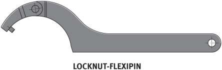
26 Jointed pin wrenches LOCKNUT-FLEXIPIN Features The jointed pin wrenches LOCKNUT-FLEXIPIN, Figure 1, are suitable for the tightening and loosening of precision locknuts AM15 to AM90 on shafts, if no tightening torque is specified. The jointed pin wrenches can be used to mount small bearings on tapered shaft seats. Tightening is achieved by means of radially arranged holes. Figure 1 Jointed pin wrench LOCKNUT-FLEXIPIN TPI 216 Schaeffler Technologies
27 Jointed pin wrenches DC LOCKNUT-FLEXIPIN Dimension table Dimensions in mm Designation Dimensions Mass Suitable for precision locknuts D L s T T 1 m min. max. kg LOCKNUT-FLEXIPIN-AM ,04 AM15, AM17 LOCKNUT-FLEXIPIN-AM ,09 AM20 LOCKNUT-FLEXIPIN-AM25-35/ ,09 AM25, AM30, AM35/58 LOCKNUT-FLEXIPIN-AM ,25 AM35, AM40, AM45, AM50, AM60 LOCKNUT-FLEXIPIN-AM ,43 AM70, AM90 Schaeffler Technologies TPI


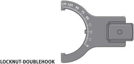
28 Double hook wrenches LOCKNUT-DOUBLEHOOK Features The double hook wrenches LOCKNUT-DOUBLEHOOK, Figure 1, are suitable for the mounting of self-aligning ball bearings and spherical roller bearings with a tapered bore. They can be used to set the radial internal clearance of these bearings precisely without the need for measurement of the radial internal clearance or the axial drive-up distance. Each double hook wrench is engraved with a torsional angle scale. Figure 1 Double hook wrench LOCKNUT-DOUBLEHOOK 0001AA2F Together with the double hook wrench, a torque wrench and mounting lever are required. For the torque wrench WRENCH20-100NM, which is used for locknuts from KM9, an adapter is also necessary, Figure 2. When the torque wrench is ordered, the adapter is included in the scope of delivery. Double hook wrench Torsional angle scale Torque wrench Adapter Mounting lever Figure 2 Double hook wrench and accessories required TPI 216 Schaeffler Technologies

29 When using double hook wrenches, the first stage involves screwing the locknut into place as far as the initial mounting position. In order to determine this position exactly, a suitable torque wrench is necessary. The double hook wrench set includes a suitable wrench of this type. In a second stage, the locknut is tightened with the aid of the torsional angle scale until the correct drive-up distance and thus the correct radial internal clearance of the bearing is achieved, Figure 3. Information on the tightening torques and torsional angles for all suitable bearings is given in the user manual BA 28 included with the double hook wrench sets. Figure 3 Use of the double hook wrench LOCKNUT-DOUBLEHOOK 00097B1D Schaeffler Technologies TPI

30 Double hook wrenches LOCKNUT-DOUBLEHOOK Double hook wrench sets LOCKNUT-DOUBLEHOOK-KM3-8-SET The double hook wrenches can be ordered as individual items or in a set. There are 2 double hook wrench sets available. The set LOCKNUT-DOUBLEHOOK-KM3-8-SET, Figure 4, comprises: 1torque wrench: LOCKNUT-DOUBLEHOOK.WRENCH10-50NM 6 double hook wrenches: LOCKNUT-DOUBLEHOOK-KM3-D16 LOCKNUT-DOUBLEHOOK-KM4-D16 LOCKNUT-DOUBLEHOOK-KM5-D16 LOCKNUT-DOUBLEHOOK-KM6-D16 LOCKNUT-DOUBLEHOOK-KM7-D16 LOCKNUT-DOUBLEHOOK-KM8-D16 1mounting lever: LOCKNUT-DOUBLEHOOK.LEVER400 1mounting paste: ARCANOL-MOUNTINGPASTE-70G 1transport case 1user manual: MATNR Figure 4 Double hook wrench set LOCKNUT-DOUBLEHOOK-KM3-8-SET 00097AD1 28 TPI 216 Schaeffler Technologies

31 LOCKNUT-DOUBLEHOOK-KM9-15-SET The set LOCKNUT-DOUBLEHOOK-KM9-15-SET, Figure 5, comprises: 1torque wrench with adapter: LOCKNUT-DOUBLEHOOK.WRENCH20-100NM LOCKNUT-DOUBLEHOOK.WRENCH-ADAPTER double hook wrenches: LOCKNUT-DOUBLEHOOK-KM9-D22 LOCKNUT-DOUBLEHOOK-KM10-D22 LOCKNUT-DOUBLEHOOK-KM11-D22 LOCKNUT-DOUBLEHOOK-KM12-D22 LOCKNUT-DOUBLEHOOK-KM13-D22 LOCKNUT-DOUBLEHOOK-KM14-D22 LOCKNUT-DOUBLEHOOK-KM15-D22 1mounting lever: LOCKNUT-DOUBLEHOOK.LEVER400 1mounting paste: ARCANOL-MOUNTINGPASTE-70G 1transport case 1user manual: MATNR Figure 5 Double hook wrench set LOCKNUT-DOUBLEHOOK-KM9-15-SET Further information User manual BA 28, LOCKNUT-DOUBLEHOOK Schaeffler Technologies TPI
32 Double hook wrenches 00097A9A LOCKNUT-DOUBLEHOOK Dimension table Designation Set Suitable for Mass Self-aligning ball bearings with tapered bore Constituent part of LOCKNUT-DOUBLEHOOK-KM3-8-SET, mass m 4,55 kg. Constituent part of LOCKNUT-DOUBLEHOOK-KM9-15-SET, mass m 6,85 kg. Spherical roller bearings with tapered bore Locknut LOCKNUT-DOUBLEHOOK-KM3-D K KM3 0, K 1303-K 2303-K LOCKNUT-DOUBLEHOOK-KM4-D K K KM4 0, K 1304-K 2304-K LOCKNUT-DOUBLEHOOK-KM5-D K K KM5 0, K K 1305-K 2305-K LOCKNUT-DOUBLEHOOK-KM6-D K K KM6 0, K K 1306-K K 2306-K LOCKNUT-DOUBLEHOOK-KM7-D K K KM7 0, K K 1307-K K 2307-K LOCKNUT-DOUBLEHOOK-KM8-D K K KM8 0, K K 1308-K K 2308-K LOCKNUT-DOUBLEHOOK-KM9-D K K KM9 0, K K 1309-K K 2309-K m kg 30 TPI 216 Schaeffler Technologies
33 Double hook wrenches 00097A9A LOCKNUT-DOUBLEHOOK Dimension table (continued) Dimensions in mm Designation Set Suitable for Mass Self-aligning ball bearings with tapered bore Constituent part of LOCKNUT-DOUBLEHOOK-KM3-8-SET, mass m 4,55 kg. Constituent part of LOCKNUT-DOUBLEHOOK-KM9-15-SET, mass m 6,85 kg. Spherical roller bearings with tapered bore Locknut LOCKNUT-DOUBLEHOOK-KM10-D K K KM10 0, K K 1310-K K 2310-K LOCKNUT-DOUBLEHOOK-KM11-D K K KM11 0, K K 1311-K K 2311-K LOCKNUT-DOUBLEHOOK-KM12-D K K KM12 0, K K 1312-K K 2312-K LOCKNUT-DOUBLEHOOK-KM13-D K K KM13 0, K K 1313-K K 2313-K LOCKNUT-DOUBLEHOOK-KM14-D K K KM14 0, K K 1314-K K 2314-K LOCKNUT-DOUBLEHOOK-KM15-D K K KM15 0, K K 1315-K K 2315-K LOCKNUT-DOUBLEHOOK.WRENCH10-50NM KM3 KM8 1,1 LOCKNUT-DOUBLEHOOK.WRENCH20-100NM KM9 KM15 2,3 LOCKNUT-DOUBLEHOOK.LEVER, KM3 KM15 0,8 m kg Schaeffler Technologies TPI
34 32 TPI 216 Schaeffler Technologies

35 Tools for dismounting Two-arm extractors Two-arm separator extractors Three-arm extractors Hydraulic pressure tool Hydraulic extractors Three-section extraction plates Internal extractors Special bearing extractors
36 Tools for dismounting Two-arm extractors Two-arm extractors PULLER-2ARM are suitable for the extraction of rolling bearings or other tightly fitted components that can be gripped from the inside or outside. Two-arm separator extractors Two-arm separator extractors PULLER-2ARM-SEPARATOR are intended specifically for the extraction of bearing rings that are in full contact with a surface and do not have extraction slots. Three-arm extractors Three-arm extractors PULLER-3ARM are suitable for the extraction of rolling bearings or other tightly fitted components that have good axial and radial accessibility for gripping from the outside. Hydraulic pressure tool The hydraulic pressure tool PULLER-SUPPORT is used in conjunction with a mechanical extractor for the loosening of tightly fitted components. Hydraulic extractors Hydraulic extractors PULLER-HYD facilitate the extraction even of larger rolling bearings. The extraction forces are applied by means of a hydraulic cylinder. Three-section extraction plates Three-section extraction plates PULLER-TRISECTION are used in conjunction with a three-arm extractor for rolling bearings or inner rings. Internal extractors Internal extractors PULLER-BORE are suitable for the dismounting of deep groove and angular contact ball bearings with a tightly fitted outer ring. In this case, the inner ring bore must be freely accessible Internal extractors PULLER-INTERNAL are suitable for the dismounting of deep groove and angular contact ball bearings with a tightly fitted outer ring without the need for dismounting of the shaft. Special bearing extractors Special bearing extractors PULLER-SPECIAL are used for the dismounting of radial bearings with a tight fit of the inner ring or outer ring under difficult conditions. 34 TPI 216 Schaeffler Technologies


37 00098B1B 00098B B B0B 00098B B AFC 00098AF AF2 Schaeffler Technologies TPI


38 Two-arm extractors PULLER-2ARM Features The two-arm extractors PULLER-2ARM, Figure 1, are suitable for the extraction of complete rolling bearings of widely varying types, of tightly fitted inner rings and of other components such as gears that can be gripped from the inside or the outside. These extractors require good radial and axial accessibility of the bearing position, possibly with extraction slots. Figure 1 Two-arm extractor PULLER-2ARM 0001AB03 The grip span is adjusted by moving the arms on the crossbar. Symmetrical adjustment is aided by a scale. During extraction, a selflocking device prevents the arms from slipping off. A rotatable insert in the spindle facilitates selection of either a pointed or round centring tip. PULLER-2ARM-SET The PULLER-2ARM-SET, Figure 2, comprises: 1two-arm extractorpuller-2arm130 1two-arm extractorpuller-2arm200 1two-arm extractorpuller-2arm350 narrow extraction arms of size 130 and 200 1tube of spindle grease 1transport case. Figure 2 PULLER-2ARM-SET 00096AFB 36 TPI 216 Schaeffler Technologies
39 Two-arm extractors 00096B3F PULLER-2ARM Dimension table Designation Set Grip span Grip depth Constituent part of PULLER-2ARM-SET, mass m 15,5 kg. Dimensions Spindle thread Extraction force w t a b G m min. max. max. Mass mm mm mm mm mm kn kg PULLER-2ARM M14 1,5 30 0,9 PULLER-2ARM M14 1,5 30 1,3 PULLER-2ARM G1/2 50 2,7 PULLER-2ARM G1/2 50 3,3 PULLER-2ARM G3/4 75 6,6 PULLER-2ARM G3/4 75 7,5 Schaeffler Technologies TPI


40 Two-arm separator extractors PULLER-2ARM-SEPARATOR Features The two-arm separator extractors PULLER-2ARM-SEPARATOR, Figure 1, are suitable for the extraction of complete rolling bearings or tightly fitted inner rings. Bearing rings can be in full contact with a surface, i.e. extraction slots are not necessary. Figure 1 Two-arm separator extractors PULLER-2ARM-SEPARATOR The separator extractor of suitable dimensions is selected in accordance with the bearing size and the mounting conditions, Figure 2. Once the separator extractor has been positioned, the screw on the clamp is rotated in order to slide the arms between the bearing ring and the locating face. This is aided by means of a special profile on the arms. Once the bearing has been wedged in this way, it is then extracted by rotating the spindle. The wedging of the bearing, in conjunction with centring on the shaft, allows gentle extraction of the bearing. Figure 2 Use of the two-arm separator extractor PULLER-2ARM-SEPARATOR 00097E1B 38 TPI 216 Schaeffler Technologies
41 Two-arm separator extractors 00096D11 PULLER-2ARM-SEPARATOR Dimension table Designation Grip span Grip depth Dimensions Spindle thread Extraction force w t a b c G m min. max. max. mm mm mm mm mm mm kn kg PULLER-2ARM-SEPARATOR , M ,55 PULLER-2ARM-SEPARATOR , M14 1,5 40 1,36 PULLER-2ARM-SEPARATOR , M20 1, Mass Schaeffler Technologies TPI


42 Three-arm extractors PULLER-3ARM Features The three-arm extractors PULLER-3ARM, Figure 1, are suitable for the extraction of complete rolling bearings of widely varying types and of tightly fitted inner rings. These extractors require good radial and axial accessibility of the bearing position, possibly with extraction slots. Figure 1 Three-arm extractor PULLER-3ARM The grip width is set by rotating the knurled disc located above the upper screw. This disc is connected to an adjustment cylinder that has two opposing threads. Due to this arrangement, the two screws rotate simultaneously, which means that the entire grip width can be covered in just a few revolutions. The arms always move symmetrically to the centre, which aids operation under unfavourable conditions. Since the arms are screw mounted, they can be reversed and operation as an internal extractor is possible. The extractor of suitable dimensions is selected in accordance with the bearing size and the mounting conditions, Figure 2. The self-centring function prevents tilting of the bearing during tightening B0B 00097E17 Figure 2 Use of the three-arm extractor PULLER-3ARM 40 TPI 216 Schaeffler Technologies
43 Three-arm extractors 00096D23 PULLER-3ARM Dimension table Designation Grip span Grip depth Dimensions Spindle thread Extraction force w t a b c G m min. max. max. mm mm mm mm mm mm kn kg PULLER-3ARM M14 1, PULLER-3ARM M PULLER-3ARM M ,5 PULLER-3ARM M PULLER-3ARM M ,8 Mass Schaeffler Technologies TPI

44 Hydraulic pressure tool PULLER-SUPPORT Features The hydraulic pressure tool PULLER-SUPPORT, Figure 1, is used for the loosening of tightly fitted parts in conjunction with mechanical extractors. Depending on the size, it generates an axial force of 80 kn or 150 kn. The spindle thread of the mechanical extraction tool is not unduly stressed as the main extraction force acts on static thread flanks. Figure 1 Hydraulic pressure tool PULLER-SUPPORT150 The hydraulic pressure tool is positioned between the spindle of the extractor and the end of the shaft. The spindle of the extractor must be in contact with the pressure tool, Figure 2. The hydraulic system is actuated by screwing in the pressure screw, Figure 3. The axial force generated in this way loosens the component to be extracted. The component can then be extracted using the mechanical spindle of the extractor. 0001AA3E 00096D2C Figure 2 Hydraulic pressure tool in combination with two-arm extractor 42 TPI 216 Schaeffler Technologies

45 0008B2E7 Figure 3 Use of the hydraulic pressure tool PULLER-SUPPORT The pressure tool PULLER-SUPPORT150 has a hydraulic return mechanism. This means that, when the pressure screw is reversed, the hydraulic piston automatically returns to the initial position. For safety reasons, the minimum size of spindle diameter and the maximum torque must be observed, see dimension table. Schaeffler Technologies TPI
46 Hydraulic pressure tool 00096D35 PULLER-SUPPORT Dimension table Designation Axial force Stroke length Section height Minimum spindle diameter of extractor Maximum torque h b m Mass kn mm mm mm Nm kg PULLER-SUPPORT M ,6 PULLER-SUPPORT M ,7 44 TPI 216 Schaeffler Technologies

47 Hydraulic extractors PULLER-HYD Features The hydraulic extractors PULLER-HYD are available with extraction forces of 40 kn to 400 kn. They facilitate simple dismounting of rolling bearings, gears, bushes and other components. Depending on the size, the hydraulic cylinders of the extractors have an integrated or a separate hydraulic hand pump. Due to the rotatable pump lever of the integrated hand pump, the operator can always adopt the optimum working position. The stroke length can be adjusted by means of the adapter included in the scope of delivery. If there is insufficient space for 3 arms, the extractor can be simply converted to 2 arms. The parts of the extractor under mechanical load are made from high quality chromium-molybdenum steel. The smooth-running piston is made from quenched and tempered steel with a chromium coating. Figure 1 Use of the hydraulic extractor PULLER-HYD in conjunction with the three-section extraction plate PULLER-TRISECTION 0008AED2 The application example, Figure 1, shows the positioning of the extractor on the bearing. Before the bearing is extracted, the safety grid or safety cover must be put in place. Schaeffler Technologies TPI

48 Hydraulic extractors PULLER-HYD Scope of delivery PULLER-HYD40 to PULLER-HYD80 When a hydraulic extractor PULLER-HYD is ordered, the extractor is supplied with the following accessories: 1adapter in the case of extractors with arms of normal length, 2adapters in the case of extractors with extended arms hydraulic cylinder with integrated or separate hydraulic pump, depending on design arms of normal length or extended arms, depending on design safety grid or safety cover, depending on size plastic or metal case, depending on size. If replacement parts for these components or arms of a different length are required, these can also be ordered as individual items. The hydraulic extractors with cylinders with an integrated hand pump PULLER-HYD40, 60 and 80 are available for extraction forces of 40 kn, 60 kn and 80 kn, Figure 2. The compact units are housed in a robust plastic case. For the protection of operating personnel, a safety grid is included. The hydraulic extractors PULLER-HYD40 are supplied with arms of normal length. The hydraulic extractors PULLER-HYD60 and PULLER-HYD80 are also available in a version with extended arms, suffix XL. Figure 2 Hydraulic extractor with integrated hand pump PULLER-HYD C 46 TPI 216 Schaeffler Technologies


49 PULLER-HYD100 to PULLER-HYD300 The hydraulic extractors with cylinders with an integrated hand pump PULLER-HYD100, 120, 200, 250 and 300 are available for extraction forces of 100 kn to 300 kn, Figure 3. The compact units are housed in a rigid metal case. For the protection of operating personnel, a safety cover is included. The hydraulic extractors PULLER-HYD100 to PULLER-HYD300 are also available in a version with extended arms, suffix XL. Figure 3 Hydraulic extractor with integrated hand pump PULLER-HYD100 PULLER-HYD400 In the case of the hydraulic extractor PULLER-HYD400 for an extraction force of 400 kn, the oil pressure is applied by means of a separate hand pump. The extractor can be therefore also be used where space is restricted. The extractor is housed together with the pump in a rigid metal case, Figure 4. For the protection of operating personnel, a safety cover is included. The hydraulic extractor PULLER-HYD400 is also available in a version with extended arms, suffix XL Figure 4 Hydraulic extractor with separate hand pump PULLER-HYD E Schaeffler Technologies TPI
50 Hydraulic extractors With integrated hand pump With separate hand pump 00096DC7 PULLER-HYD with integrated hand pump Dimension table Designation Grip span Grip depth Dimensions Stroke Extraction Mass w t a b length force m max. max. mm mm mm mm mm kn kg PULLER-HYD ,5 PULLER-HYD ,9 PULLER-HYD60 -XL ,1 PULLER-HYD ,7 PULLER-HYD80-XL PULLER-HYD ,2 PULLER-HYD100-XL ,8 PULLER-HYD ,6 PULLER-HYD120-XL ,6 PULLER-HYD ,6 PULLER-HYD200-XL ,1 PULLER-HYD ,2 PULLER-HYD250-XL PULLER-HYD PULLER-HYD300-XL ,7 PULLER-HYD ,6 PULLER-HYD400-XL PULLER-HYD with separate hand pump TPI 216 Schaeffler Technologies
51 Hydraulic extractors Arms for extractors PULLER-HYD..JAW Dimension table Dimensions in mm Designation Dimensions As replacement part As accessory Mass a b for extractor with extended arms for extractor m kg PULLER-HYD40.JAW PULLER-HYD40 3,1 PULLER-HYD60.JAW PULLER-HYD60 3,1 PULLER-HYD60.JAW-LONG PULLER-HYD60-XL PULLER-HYD60 4,5 PULLER-HYD80.JAW PULLER-HYD80 4,8 PULLER-HYD80.JAW-LONG PULLER-HYD80-XL PULLER-HYD80 5,9 PULLER-HYD100.JAW PULLER-HYD100 4,2 PULLER-HYD100.JAW-LONG PULLER-HYD100-XL PULLER-HYD100 5,7 PULLER-HYD120.JAW PULLER-HYD120 7,1 PULLER-HYD120.JAW-LONG PULLER-HYD120-XL PULLER-HYD120 8,6 PULLER-HYD200.JAW PULLER-HYD200 9,1 PULLER-HYD200.JAW-LONG PULLER-HYD200-XL PULLER-HYD200 12,3 PULLER-HYD250.JAW PULLER-HYD250 14,5 PULLER-HYD250.JAW-LONG PULLER-HYD250-XL PULLER-HYD PULLER-HYD300.JAW PULLER-HYD300 24,8 PULLER-HYD300.JAW-LONG PULLER-HYD300-XL PULLER-HYD300 44,2 PULLER-HYD400.JAW PULLER-HYD400 64,6 PULLER-HYD400.JAW-LONG PULLER-HYD400-XL PULLER-HYD400 71,5 A delivered unit always comprises 3 arms including the star-shaped retaining device. Schaeffler Technologies TPI
52 Hydraulic extractors Cylinder with integrated hand pump Cylinder with separate hand pump 00097DFC PULLER-HYD..CYLINDER Dimension table Designation Stroke length Extraction force Hydraulic pressure max. Oil quantity Suitable for extractor Mass mm kn bar l kg PULLER-HYD40.CYLINDER ,6 PULLER-HYD40 2,6 PULLER-HYD60.CYLINDER ,8 PULLER-HYD60 (60XL) 3 PULLER-HYD80.CYLINDER ,2 PULLER-HYD80 (80XL) 3,6 PULLER-HYD100.CYLINDER ,8 PULLER-HYD100 (100XL) 2,9 PULLER-HYD120.CYLINDER ,2 PULLER-HYD120 (120XL) 3,4 PULLER-HYD200.CYLINDER PULLER-HYD200 (200XL) 4,2 PULLER-HYD250.CYLINDER ,3 PULLER-HYD250 (250XL) 7,2 PULLER-HYD300.CYLINDER ,3 PULLER-HYD300 (300XL) 9,3 PULLER-HYD400.CYLINDER ,3 PULLER-HYD400 (400XL) 18 PULLER-HYD400.PUMP ,3 PULLER-HYD400 (400XL) 7,3 m 50 TPI 216 Schaeffler Technologies
53 Hydraulic extractors Adapters Safety grid Safety cover 00097DA PULLER-HYD.ADAPTER Safety cover Dimension table Dimensions in mm Designation Dimensions Suitable Mass D L for extractor m kg PULLER-HYD.ADAPTER-D25/L PULLER-HYD40 (60, 100, 100XL) 0,18 PULLER-HYD.ADAPTER-D28/L PULLER-HYD80 (120, 120XL) 0,25 PULLER-HYD.ADAPTER-D35/L PULLER-HYD200 (200XL, 175, 175XL) 0,45 PULLER-HYD.ADAPTER-D45/L PULLER-HYD250 (250XL) 0,95 PULLER-HYD.ADAPTER-D55/L PULLER-HYD300 (300XL) 1,65 PULLER-HYD.ADAPTER-D69/L PULLER-HYD400 (400XL) 2,55 PULLER-HYD.ADAPTER-D69/L PULLER-HYD400 (400XL) 3,7 Dimension table Dimensions in mm Designation Suitable for extractor Design PULLER-HYD40.NET PULLER-HYD40 Safety grid PULLER-HYD60.NET PULLER-HYD60XL.NET PULLER-HYD80.NET PULLER-HYD80XL.NET PULLER-HYD60 PULLER-HYD60XL PULLER-HYD80 PULLER-HYD80XL PULLER-HYD100.NET PULLER-HYD100 Safety cover PULLER-HYD100XL.NET PULLER-HYD120.NET PULLER-HYD120XL.NET PULLER-HYD200.NET PULLER-HYD200XL.NET PULLER-HYD250.NET PULLER-HYD250XL.NET PULLER-HYD300.NET PULLER-HYD300XL.NET PULLER-HYD400.NET PULLER-HYD400XL.NET PULLER-HYD100XL PULLER-HYD120 PULLER-HYD120XL PULLER-HYD200 PULLER-HYD200XL PULLER-HYD250 PULLER-HYD250XL PULLER-HYD300 PULLER-HYD300XL PULLER-HYD400 PULLER-HYD400XL Schaeffler Technologies TPI


54 Three-section extraction plates PULLER-TRISECTION Features The three-section extraction plates PULLER-TRISECTION, Figure 1, are used for the extraction of complete bearings or tightly fitted inner rings. Figure 1 Three-section extraction plate PULLER-TRISECTION The extraction plates are mainly suitable for mounting situations where a three-arm extractor on its own cannot be used to achieve gentle extraction by means of the inner ring. This can be the case, for example, where there are no extraction slots or the bearing rings are wide, if the arms cannot grip the inner ring. Good radial access to the bearing position is required. Extraction of inner rings and complete rolling bearings without damage is possible with proper handling. The three extraction plates are pushed, by means of alternately screwing in the nuts, between the shaft shoulder and inner ring. The bearing is extracted by means of an extractor that is inserted into the plates, Figure E Figure 2 Use of the three-section extraction plate PULLER-TRISECTION 52 TPI 216 Schaeffler Technologies

55 Three-section extraction plates 00096D3E PULLER-TRISECTION Dimension table Dimensions in mm Designation Dimensions Recommended for extractor Mass d B PULLER-HYD PULLER-3ARM m min. max. kg PULLER-TRISECTION ,43 PULLER-TRISECTION , 60, 80, ,27 PULLER-TRISECTION , 100, 120, 175, ,07 PULLER-TRISECTION , 200, 250, ,4 PULLER-TRISECTION , 300, ,2 Schaeffler Technologies TPI


56 Internal extractors PULLER-BORE Features The internal extractors PULLER-BORE are suitable for the dismounting of deep groove and angular contact ball bearings with a tightly fitted outer ring. In this case, the inner ring bore must be freely accessible. The internal extractors can be used for bearings with bore diameters of 5 mm to 79,5 mm. Since the extraction force is directed through the rolling elements, the possibility of bearing damage cannot be excluded. The gripping segments of the internal extractor are spread when the threaded spindle is tightened. The lip of the gripping segments is pressed against the back of the bearing inner ring bore. The bearing is then extracted with the aid of the countersupport and its threaded spindle, Figure 1. Figure 1 Internal extractor PULLER-BORE with countersupport 0008BD2D As an alternative to the countersupport, an impact extractor comprising a rod and an impact weight can be used. The internal extractor is screwed onto the rod. The bearing is then dismounted by applying impacts to the rear end of the impact extractor by means of the impact weight, Figure 2. Figure 2 Internal extractor PULLER-BORE with impact extractor B4 54 TPI 216 Schaeffler Technologies

57 Internal extractor sets The internal extractors can be ordered as individual items or in a set. There are 2 internal extractor sets available. PULLER-BORE5-39-SET The internal extractor set PULLER-BORE5-39-SET, Figure 3, comprises: 1countersupport PULLER-BORE.HOLDER impact extractor PULLER-BORE.IMPACT-90 6internal extractors PULLER-BORE.GRIPPER-5-6 PULLER-BORE.GRIPPER-7-9 PULLER-BORE.GRIPPER PULLER-BORE.GRIPPER PULLER-BORE.GRIPPER PULLER-BORE.GRIPPER tube of spindle grease 1transport case. Figure 3 Internal extractor set PULLER-BORE5-39-SET 00098FB3 Schaeffler Technologies TPI

58 Internal extractors PULLER-BORE PULLER-BORE40-79-SET The internal extractor set PULLER-BORE40-79-SET, Figure 4, comprises: 1countersupport PULLER-BORE.HOLDER impact extractor PULLER-BORE.IMPACT-300 4internal extractors PULLER-BORE.GRIPPER PULLER-BORE.GRIPPER PULLER-BORE.GRIPPER PULLER-BORE.GRIPPER tube of spindle grease 1transport case. Figure 4 Internal extractor set PULLER-BORE40-79-SET 00098FCE 56 TPI 216 Schaeffler Technologies

59 Internal extractors 00097A9E PULLER-BORE.GRIPPER Dimension table Designation Set Grip width for bore diameter Constituent part of PULLER-BORE5-39-SET, mass m 3,75 kg. Constituent part of PULLER-BORE40-79-SET, mass m 7,3 kg. Grip depth Impact travel Support diameter Thread of support base w t L a G m min. max. min. max. Mass mm mm mm mm mm mm kg PULLER-BORE.GRIPPER ,5 35 0,09 PULLER-BORE.GRIPPER ,5 35 0,09 PULLER-BORE.GRIPPER ,5 35 0,1 PULLER-BORE.GRIPPER ,5 45 0,13 PULLER-BORE.GRIPPER ,5 50 0,18 PULLER-BORE.GRIPPER ,5 90 0,25 PULLER-BORE.GRIPPER ,5 95 0,55 PULLER-BORE.GRIPPER ,5 95 0,74 PULLER-BORE.GRIPPER ,5 95 0,88 PULLER-BORE.GRIPPER ,5 95 0,76 PULLER-BORE.IMPACT ,2 PULLER-BORE.IMPACT ,4 PULLER-BORE.HOLDER M ,57 PULLER-BORE.HOLDER M , E E05 PULLER-BORE.IMPACT PULLER-BORE.HOLDER Schaeffler Technologies TPI

60 Internal extractors PULLER-INTERNAL SET Features The internal extractors PULLER-INTERNAL are used for the dismounting of standard deep groove ball bearings with a tightly fitted outer ring without dismounting of the shaft, Figure 1. They are suitable for rolling bearings with a bore diameter of 10 mm to 100 mm. Figure 1 Use of the internal extractor PULLER-INTERNAL D8 Three extraction arms grip under the outer ring shoulder of the deep groove ball bearing. The suitable combination of arms and threaded spindle for the bearing size can be found in the selection table, see table. Selection table for arms and spindle Deep groove ball bearings Arms Spindle A1 M A A A4 M A TPI 216 Schaeffler Technologies

61 Selection table for arms and spindle (continued) Deep groove ball bearings Arm Spindle A6 M The spindles and arms can be ordered as individual items or in a set. PULLER-INTERNAL SET The internal extractor set PULLER-INTERNAL SET, Figure 2, comprises: 6 kits each containing 3 arms: PULLER-INTERNAL.ARM-A1-KIT PULLER-INTERNAL.ARM-A2-KIT PULLER-INTERNAL.ARM-A3-KIT PULLER-INTERNAL.ARM-A4-KIT PULLER-INTERNAL.ARM-A5-KIT PULLER-INTERNAL.ARM-A6-KIT 2spindles with nut PULLER-INTERNAL.SPINDLE-M12 PULLER-INTERNAL.SPINDLE-M16 1tube of spindle grease 1transport case. Figure 2 Internal extractor set PULLER-INTERNAL SET Schaeffler Technologies TPI
62 Internal extractors Arms Spindles 00097AA AA8 PULLER-INTERNAL.ARM PULLER-INTERNAL.SPINDLE Dimension table Designation Set Arm length Size Arms Spindle Mass a thread m mm Quantity kg PULLER-INTERNAL.ARM-A1-KIT 140 A1 3 0,14 PULLER-INTERNAL.ARM-A2-KIT 140 A2 3 0,15 PULLER-INTERNAL.ARM-A3-KIT 140 A3 3 0,16 PULLER-INTERNAL.ARM-A4-KIT 170 A4 3 0,31 PULLER-INTERNAL.ARM-A5-KIT 170 A5 3 0,34 PULLER-INTERNAL.ARM-A6-KIT 170 A6 3 0,41 PULLER-INTERNAL.SPINDLE-M12 M12 0,32 PULLER-INTERNAL.SPINDLE-M16 M16 0,66 Constituent part of PULLER-INTERNAL SET, mass m 3,5 kg. 60 TPI 216 Schaeffler Technologies

63 Special bearing extractors PULLER-SPECIAL Features The special bearing extractors PULLER-SPECIAL, Figure 1, are used for the dismounting of radial bearings with a tight fit of the inner ring or outer ring. They are required if the bearing rings cannot be gripped using conventional extractors. They are also suitable for cases where the inner ring is in contact with a shaft shoulder that does not have extraction slots. This also applies if the bearing in a housing must be removed from the shaft. The special bearing extractors comprise a base device and a collet. Extraction of the bearing without damage is possible with proper handling. The maximum shaft diameter is 75 mm. Figure 1 Special bearing extractor PULLER-SPECIAL B A differentiation is made between 4 extraction principles, see page 64. The extraction principle depends on the bearing design and the mounting position. The collet grips the bearing ring by the maximum possible circumferential surface. Depending on the extraction principle, the finger-shaped extensions of the collet engage between the rolling elements on the raceway edge of the inner ring, behind the rollers in tapered roller bearings or by wedging behind the chamfer of the bearing ring to be extracted. Schaeffler Technologies TPI


64 Special bearing extractors PULLER-SPECIAL For use, a collet is screwed into the base device and positioned on the bearing, Figure 2. The collet is closed using the left hand thread of the union nut and clamped against one of the bearing rings, Figure 3. The extraction force is generated by a threaded spindle, Figure B Figure 2 PULLER-SPECIAL: positioning on the bearing Figure 3 PULLER-SPECIAL: tensioning of the collet on the bearing D F0 Figure 4 PULLER-SPECIAL: extraction of the bearing 62 TPI 216 Schaeffler Technologies

65 Selecting the special bearing extractor Base device When selecting the base device and collet, the size of the bearing and the extraction principle necessary for the application must be taken into consideration. The base device is selected so that its inside diameter d is larger than the bore diameter of the bearing. For the deep groove ball bearing 6015 (bore diameter = 75 mm), for example, the base device PULLER-SPECIAL-BASIC77 (d = 77 mm) must be selected. For applications in which the bearing must be pushed a particularly long distance onto the shaft, extensions are available for the base devices, Figure Base device Base device with extension Figure 5 PULLER-SPECIAL with tapered roller bearing Collet Ordering designation The gripping profile of collets must be matched to the geometry of the bearing to be extracted. The extraction principle and thus the collet depends on the bearing design and the mounting position. Two collets are always required for tapered roller bearings in X and Oarrangements. Since the number of rolling elements is not standardised, different collets may be required for the same bearing sizes from different manufacturers. The bearing manufacturer must always be stated at the time of ordering. The ordering designation of a collet comprises: PULLER-SPECIAL the extraction principle the bearing designation. Example: PULLER-SPECIAL-A Schaeffler Technologies TPI


66 Special bearing extractors PULLER-SPECIAL Extraction principles Extraction principle A The extraction principle depends on the bearing design and the mounting situation, Figure 6 to Figure 9. In the case of tapered roller bearings arranged in pairs in an X and O arrangement, the extraction principle B is used for one bearing and the extraction principle C for the other bearing. The extraction principle A is used for deep groove, angular contact and self-aligning ball bearings, four point contact bearings, ball bearings with a split inner ring and roller bearings. For extraction, the inner ring of the bearing is gripped. Extraction is therefore also possible if the bearing is located in the housing in such a way that the bearing cannot be gripped either from the inside or from the outside. This extraction principle can also be used to grip bearings that are located deep in a housing if the outside diameter of the bearing is greater than the outside diameter of the base device. Figure 6 Extraction principle A Extraction principle B The extraction principle B is used for tapered roller bearings mounted in an X or O arrangement. The gripper reaches over the rollers, irrespective of their number. The internal profile of the collet is matched to the rollers and their angle. With certain bearing dimensions, deeply located bearings can also be extracted. The outer ring must be removed in advance EFF Figure 7 Extraction principle B 00097F03 64 TPI 216 Schaeffler Technologies


67 Extraction principle C The extraction principle C is used for tapered roller bearings mounted in an X or O arrangement. The collet engages behind the large rib of the inner ring. The possibility of gripping behind is predetermined by the bearing geometry and is normally small, which requires high precision in the manufacture of the collets. The outer ring must be removed in advance. Figure 8 Extraction principle C Extraction principle D The extraction principle D is used for a wide variety of bearing types. Examples include the inner rings of cylindrical roller bearings, angular contact ball bearings and magneto bearings, the second inner ring half of four point contact bearings and the outer rings of deep groove ball bearings, spherical roller bearings and needle roller bearings. Other components such as ABS rings or gears can also be extracted using extraction principle D. In the extraction of rolling bearings, wedging of the rolling bearing is carried out on the chamfer of the bearing ring F07 Figure 9 Extraction principle D Ordering example Ordering example for special bearing extractor and collet for cylindrical roller bearing NU315: Tool Base device Collet Ordering designation PULLER-SPECIAL-BASIC77 PULLER-SPECIAL-D-NU F0C Schaeffler Technologies TPI


68 Special bearing extractors PULLER-SPECIAL Special tools PULLER-SPECIAL-CUSTOM In addition to the special bearing extractors with base device and collet, other designs are available. These are available by agreement. Larger extraction collets do not include the base device. In this case, the collet is tensioned by means of a locking collar and the bearing is extracted from the shaft by means of a hydraulic cylinder, Figure 10. Extractors of the type are manufactured by agreement as a customer-specific solution. Figure 10 Special bearing extractor PULLER-SPECIAL-CUSTOM PULLER-SPECIAL-E The extractor PULLER-SPECIAL-E is a tool for the dismounting of spherical roller bearings and toroidal roller bearings, Figure 11. The dismounting tool has specially produced fingers that grip behind the end faces of the rollers. The extractor then presses on the shaft by means of a hydraulic cylinder and pulls the bearing out. The tight fit of the bearing inner ring must have been removed in advance, for example by the use of a hydraulic system for the oil pressure method. The most frequent application for the extractor PULLER-SPECIAL-E is found in paper machinery F1 Figure 11 Special bearing extractor PULLER-SPECIAL-E 0008AF8F 66 TPI 216 Schaeffler Technologies
HMZ Locknuts simple and reliable locking devices
 simple and reliable locking devices Technical Product Information A Member of the Schaeffler Group Application Characteristics Application The new HMZ locknuts are easy to handle, permitting accurate and
Zero Point Clamping System. ZERO lock BALL lock
 Zero Point Clamping System ZERO lock BALL lock kap3 kap 263 Technical information regarding ZERO lock Zero Point Clamping System Application The modularly designed, flexible ZERO lock Zero-Point Clamping
Clamping devices 521
 Clamping devices 521 522 Product overview Clamping devices Adjustable straps K0001 Hook clamps K0012 Goose-neck straps with long slot K0002 Page 526 Hook Clamps with collar K0013 Page 535 Equipped clamps
Repair Manual MWS45A-MWS50A-MWS55A MW32A-MWS36A-MWS40A. Ref Rev.D General Pump is a member of the Interpump Group
 MW/S 8 Repair Manual MWS45A-MWS50A-MWS55A MW32A-MWS36A-MWS40A General Pump is a member of the Interpump Group INDEX 1. INTRODUCTION..................................................Page 3 2. REPAIR INSTRUCTIONS...........................................Page
Decide what reach is required. This must be at least equal to or larger than the depth of the part which needs removal. Safe Working Load (tonnes)
") Sykes-Pickavant pullers are manufactured to a very high specification and subjected to rigorous testing - far exceeding their stated capacities. The legs and beams are drop forged from high quality steel
Sykes-Pickavant pullers are manufactured to a very high specification and subjected to rigorous testing - far exceeding their stated capacities. The legs and beams are drop forged from high quality steel
Page 1. SureMotion Quick-Start Guide: LARSACC_QS 1st Edition - Revision A 03/15/16. Standard Steel Bolt/Screw Torque Specifications
 R K C T I Repair Kit Product Compatibility Repair Kit # Linear Actuator Assembly # LARSACC-013 LARSACC-014 LARSD2-08T12BP2C (12-in travel) LARSD2-08T24BP2C (24-in travel) C P I R K 1 ea Ball Screw with
REPAIR INSTRUCTIONS. Cat. No Cat. No MILWAUKEE ELECTRIC TOOL CORPORATION. SDS Max Demolition Hammer. SDS Max Rotary Hammer
 Cat. No. 9-0 SDS Max Demolition Hammer Cat. No. -0 SDS Max Rotary Hammer MILWAUKEE ELECTRIC TOOL CORPORATION W. LISBON ROAD BROOKFIELD, WISCONSIN 00-0 8-9-0 d 000 8-9-0 d Special Tools Require Forcing
General Four-Way Operation, Maintenance & Service Manual
 General Four-Way Operation, Maintenance & Service Manual SCOPE Included in the following pages you will find assembly drawings, exploded views, parts lists, assembly tips, operational descriptions and
BETEX MECHANICAL PULLERS. BETEX MSP 2/3-arm pullers, self-centering. Safe and easy dismounting of bearings, couplings, rings etc.
 BETEX MSP 2/3-arm pullers, self-centering Safe and easy dismounting of bearings, couplings, rings etc. Ergonomic design, easily operated by one person! Practical! Self centering 2 or 3-arm puller with
Technical Manual ETP-TECHNO. Content
 Technical Manual ETP-TECHNO Content Technical parts description...2 Mounting/dismantling tips...3 Design examples/tips...5 Technical data...8 Machining in the flange...9 FAQ...10 Spare parts...11 1 Technical
MODEL D DIESEL PILE HAMMER
 AMERICAN PILEDRIVING EQUIPMENT, INC. MODEL D125-42 DIESEL PILE HAMMER SPARE PARTS BOOK Corporate Office 7032 S. 196th Street Kent, WA, USA 98032 Tel: 1-800-248-8498 Tel: 1-253-872-0141 Fax: 1-253-872-8710
ELECTRIC TOOL CORPORATION
 Cat. No. -0 / Hex Demolition Hammer Cat. No. 0-0 Spline Rotary Hammer MILWAUKEE ELECTRIC TOOL CORPORATION W. LISBON ROAD BROOKFIELD, WISCONSIN 00-0 -9-00 d 000 -9-00 d SpecialTools Require Forcing discs
SPIETH Locknuts. Series MSW. Works Standard SN 04.03
 SPIETH Locknuts Series MSW Works Standard SN 0.03 SPIETH Locknuts Series MSW SPIETH locknuts offer a range of technical benefits, qualified by their special system and production. Under high levels of
Clamping bolts Eccentrical cams clamping units
 2.3 Shaft Clamping bolts Eccentrical cams clamping units 2.9 2.8 2.7 2.6 2.5 2.4 2.3 2.2 2.1 2.3 Clamping bolts, Eccentrical cams, Shaft clamping units Page 641 2.3 Clamping bolts, Eccentrical cams, Shaft
Ensat driving tools...
 nsat driving tools... On this page, you can configure the optimum tool for your application. A configuration is provided in the following as an illustrative example. The article number is composed of two
Repair Manual MK40A-MK45A-MK50A MK55A-MK60A-MK65A. Ref Rev.C General Pump is a Member of The Interpump Group
 MK Repair Manual MK40A-MK45A-MK50A MK55A-MK60A-MK65A General Pump is a Member of The Interpump Group 8 INDEX 1. INTRODUCTION..................................................Page 3 2. REPAIR INSTRUCTIONS...........................................Page
Maintenance Information
 16601023 Edition 2 January 2014 Air Impact Wrench 2705P1 Maintenance Information Save These Instructions Product Safety Information WARNING Failure to observe the following warnings, and to avoid these
adaptivemechanical adaptive
 Mechanical clamping elements mechanical 6 Content Product group 6 Sliding clamp, mechanical 6.2210 Clamping block, mechanical 6.2212 High-pressure spindle, mechanical with integral wedge system 6.2270
NEWS Part. N /0 MINITEC NEWS
 NEWS 2009 Part. N 95.0423/0 MINITEC NEWS 2009 1 TABLE OF CONTENT INTRODUCTION CONTENTS 3 END CAP Z WITH HAMMER TAPS 3 END CAP 45X45 VA 4 ANGLE 25 GD-Z 4 ANGLE 45X90 GD-Z 5 ANGLE 90 GD-Z 5 HINGE 19 S 6
Choosing the right puller for the job. Types of Puller
 Pullers Sykes-Pickavant pullers are manufactured to a very high specification and subjected to rigorous testing - far exceeding their stated capacities. The legs and beams are drop forged from high quality
Pull-down clamps. No Low height clamping jaws, model Bulle
 Pull-down clamps The wedge action of clamping jaws is the characteristic feature of these pull down clamps. It causes the pull down effect, which presses the workpiece against both, stop and machine table.
1. TABLE OF CONTENT 2. ASSEMBLY ATEX. PENCOflex Installation Instructions & Service Manual
 ATEX 1. TABLE OF CONTENT 1. Table Of content... 1 2. Assembly... 1 3. Alignment... 2 4. Earthing... 3 5. Inspection and replacement of Elastic elements... 4 5.1. Rubber elements... 4 5.2. Pins... 4 5.2.1
Click Here to Go Back
 Click Here to Go Back Fig. -94 Fig. -97 CC42D 10. Remove the cap screw securing the gear shift stopper plate pin retainer; then remove the retainer. Fig. -95 CC45D 12. Remove the link arm and account for
SERVICE PARTS LIST. M18 FUEL SAWZALL Reciprocating Saw F56A BULLETIN NO CATALOG NO
 47(5x) 46 45 00 44 0 59 43 42 84 51 57 46 47 48 59 83 64 77 48 47(2x) 49(2x) 40 58 See service note on page 5 41 82 51 40 41 42 43 44 45 87 52 27 28 34 57 29 (6x) 60 28 EXAMPLE: Component Parts (Small
Technical Manual. ETP-CLASSIC incl type R. Content
 Technical Manual ETP-CLASSIC incl type R Content Technical parts description...2 Mounting/dismantling tips...4 Design suggestions...7 Tolerances...13 Central bolt...15 Torsional stiffness...16 Screw pitch
OPERATING INSTRUCTIONS 5-AXIS CLAMPING SYSTEM + ACCESSORIES
 OPERATING INSTRUCTIONS 5-AXIS CLAMPING SYSTEM + ACCESSORIES 1 Contents 1. Introduction 2. Safety instructions and precautions 3 Operating the clamp 3.1 Clamp set up 3.2 Sequence for clamp set up 3.3 Adjusting
5-axis clamping system compact
 5-axis clamping system compact 395 5-axis clamping system compact Function We are setting standards with the new KIPP 5-axis clamping system compact in this field. The system was specifically designed
Roller Guides C-Rail Systems Linear Guide Systems Ball-Bearing Guide Bushes Ball-bush block guides Shafts Accessories for Linear Slides
 Roller Guides C-Rail Systems Linear Guide Systems Ball-Bearing Guide Bushes Ball-bush block guides Shafts Accessories for Linear Slides Application example linear systems, drives and accessories 1 2 3
Technical features. Positive Taper Lock System for manual tool clamping. Technical features:
 clamping set Technical features The RÖHM- was specially designed for the positive taper lock clamping taking particulary into account the necessity of manual clamping. Technical features: strong design
LK36-LK40-LK45 LK50-LK55-LK60
 LK Repair Manual LK36-LK40-LK45 LK50-LK55-LK60 INDEX 1. INTRODUCTION..................................................Page 3 2. REPAIR INSTRUCTIONS...........................................Page 3 2.1
Fisher 667 Diaphragm Actuators Size 80 and 100
 Instruction Manual 667 Size 80 and 100 Actuators Fisher 667 Diaphragm Actuators Size 80 and 100 Contents Introduction... 1 Scope of Manual... 1 Description... 2 Specifications... 2 Maximum Pressure Limitations...
RTI TECHNOLOGIES, INC.
 RTI TECHNOLOGIES, INC. BRC500 & BRC550 Arbor/Spindle Mechanism Adjustment & Service Technical Instructions The arbor/spindle mechanism of the BRC500/550 is designed to be robust for long life. Occasionally
PROPELLER SHAFT GROUP CONTENTS GENERAL INFORMATION SPECIAL TOOLS SERVICE SPECIFICATIONS PROPELLER SHAFT...
 25-1 GROUP 25 CONTENTS GENERAL INFORMATION........ 25-2 SERVICE SPECIFICATIONS....... 25-2 LUBRICANTS.................. 25-2 SEALANT...................... 25-2 SPECIAL TOOLS................ 25-2.............
DRIVE COMPONENTS REMOVAL. 9. FXCW/C: see Figure Remove bolt (9), sprocket retainer (8), and thrust washer (7). NOTE PRIMARY DRIVE LOCKING TOOL
, sprocket retainer (8), and thrust washer (7). NOTE PRIMARY DRIVE LOCKING TOOL") DRIVE COMPONENTS REMOVAL PART NUMBER HD-7977 TOOL NAME PRIMARY DRIVE LOCKING TOOL S To remove the primary chain, remove compensating sprocket, clutch assembly and primary chain as an assembly:. Remove
DRIVE COMPONENTS REMOVAL PART NUMBER HD-7977 TOOL NAME PRIMARY DRIVE LOCKING TOOL S To remove the primary chain, remove compensating sprocket, clutch assembly and primary chain as an assembly:. Remove
3.2.3 Rear Door Window and Quarter Window Carrier Assembly
 Tighten all bolts. Tighten bolts marked -1- and -2- in specified sequence. Tightening torque: 8 Nm Remaining bolts can be tightened in any sequence. Insert door window -3- through window recess without
MSR/MSB Mechanical Setting Tool
 Tech Unit No: 0620000004 Revision: B Approved By: Quality Engineer Date: 2014-12-16 MSR/MSB Mechanical Setting Tool FEATURES: Special designed Bow Spring provides positive control and allows one size Mechanical
PREASSEMBLED ELEMENTS FOR LIFTING AND SLIDING DOORS
 PROFILE SYSTEM PRE-ASSEMBLED ELEMENTS FOR LIFTING AND SLIDING DOORS s r ood gni d i l s dna gni t f i l r o f s t neme l e de l bme s s a - er P PREASSEMBLED ELEMENTS FOR LIFTING AND SLIDING DOORS MINITEC
HEAVY DUTY CENTRIFUGAL PUMPS
 HEAVY DUTY CENTRIFUGAL PUMPS Supplemental Assembly Manual DryLock 1 Static Seal Cartridge 1. Place the slide rings (24A & 24B) into the bore of the rotary seal housing (24). The shortest slide ring goes
Diesel Pile Hammer D30-32 Part # 66508
 Diesel Pile Hammer D30-32 Part # 66508 2 Diesel Pile Hammer D30-32 Part # 66508 Pos Order No Pg Description Qty 66508 Diesel Pile Hammer D30-32 cmpl 1 1 108742 4 Cylinder Lower Part cmpl 1 2 60151 Inner
ADDUCO Hydraulic Clamping Nut
 Translation of Original Operating Manual ADDUCO Hydraulic Clamping Nut Assembly and Operating Manual Superior Clamping and Gripping Imprint Imprint Copyright: This manual remains the copyrighted property
WSG 8-115; 8-125; P; WSG ; WSG P; WSG PS; WSG P; WSG 15-70Inox
 Repair instructions Page of 47 Contents. Models described 2. Technical data 3. Notes and requirements 4. Tools required 5. Lubricants and auxiliary substances required 6. Disassembly 7. Assembly 8. Connection
Hydrajaws Safety Lifeline Tester
 Hydrajaws Safety Lifeline Tester Operating Instructions HYDR AJAWS LIMITED Hydrajaws Safety Lifeline Tester 4 5 1 6 7 2 3 9 10 8 12 11 TECHNICAL SPECIFICATIONS Load Gauges Range available: Analogue: 0-25kN/lb/f
The Ensat self-tapping threaded
 The nsat self-tapping threaded insert nsat is a self-tapping threaded insert with external and internal threads,cutting slots or cutting bores. A continuous process of further development has brought about
The Ensat self-tapping threaded insert...
 The nsat self-tapping threaded insert... nsat is a self-tapping threaded insert with external and internal thread, cutting slots or cutting bores. A continuous process of further development has brought
MSR/MSB Mechanical Setting Tool
 Tech Unit No: 0620000004 Revision: C Approved By: Quality Engineer Date: 201-1-9 MSR/MSB Mechanical Setting Tool FEATURES: Special designed Bow Spring provides positive control and allows one size Mechanical
PEDESTAL OVERHAUL. Some of the tools for a pedestal overhaul. Pedestal work stand
 INTRODUCTION A properly greased labyrinth seal will help prevent dust and water damage to the pedestal bearing oil supply and shaft seal area. Properly greased and oiled pedestals rarely require an overhaul.
HP-10 Hand Puller Operator Manual
 401 Andover Park East Seattle, Washington 98188-7605 USA (206) 246-2010 FTI OPERATIONS, MAINTENANCE AND REPAIR MANUAL HP-10 Hand Puller Operator Manual Part #2720-076, Log #3243 Published February 2006
5-AXIS MACHINING SCS QUINTUS WWW. WORKHOLDINGSOLUTIONSGROUP. COM
 WORKHOLDING SOLUTIONS FOR -AXIS MACHINING SCS MC QUINTUS ONE system / MANY solutions WWW. WORKHOLDINGSOLUTIONSGROUP. COM MCCLAMPING S YSTEM for -axis machining MC + Quintus... MC Clamping System Free access
Adjustable Feet Castors Accessories for Floor Elements
 Adjustable Feet Castors Accessories for Floor Elements Products in this section Levelling Knuckle Feet Threaded spindles for infinite height adjustment Metal or plastic foot plate Knuckle Feet X Compatible
Daily Maintenance. 2. Insert bobbin cases in to rotary hooks. Make sure bobbin thread is not over 2 inches long. Close bobbin case covers.
 Rotary hook 1. Open bobbin case covers and remove bobbin cases. Use brush to remove lint build up in and around rotary hooks. Compressed air may also be used. Daily Maintenance Cle aning Oiling Rotary
Industrial Drill Chucks with Key. For Stationary Machines and Portable Drilling Machines. Diameter (mm)
") Drilling Industrial Drill Chucks with Key For Stationary Machines and Portable Drilling Machines Specifically designed for stationary drilling, turning, milling and wood working machines The one-piece
Drilling Industrial Drill Chucks with Key For Stationary Machines and Portable Drilling Machines Specifically designed for stationary drilling, turning, milling and wood working machines The one-piece
Instruction Manual. Manual Furniture Mover. Note: Owner/Operator must read and understand this instruction manual before using the furniture mover.
 Instruction Manual Manual Furniture Mover Note: Owner/Operator must read and understand this instruction manual before using the furniture mover. I - Contents 1. Application 2 Specifications 3.Assembly
MKS. MKS Series MKS 40 MKS 45 MKS 50 MKS 55 MKS 60 MKS 65. Repair Manual
 MKS Series MKS 40 MKS 45 MKS 50 MKS 55 MKS 60 MKS 65 Repair Manual INDEX. INTRODUCTION 3 2. REPAIR INSTRUCTIONS 3 2. Crank Mechanism Repair...3 2.. Crank Mechanism Disassembly...4 2..2 Crank Mechanism
COROMANT CAPTO Spindle clamping set handbook.
 Version 5.08 Supersedes 5.07 COROMANT CAPTO Spindle clamping set handbook. C-2920:20 Subject to changes without notice. Content Page. 1. Safety Instruction 3 2. Description 4-7 3. Order codes 8-10 4. Installation
ROTARY TABLE OPERATION AND SERVICE MANUAL HORIZONTAL AND VERTICAL. Horizontal & Vertical. Rotary Table (HVRT) Tilting Rotary Table
 Tilting Rotary Table") Horizontal & Vertical Rotary Table (HVRT) OPERATION AND SERVICE MANUAL Tilting Rotary Table Horizontal & Vertical Rapid Indexer VERTICAL AND HORIZONTAL ROTARY TABLE This Horizontal & vertical table is
Horizontal & Vertical Rotary Table (HVRT) OPERATION AND SERVICE MANUAL Tilting Rotary Table Horizontal & Vertical Rapid Indexer VERTICAL AND HORIZONTAL ROTARY TABLE This Horizontal & vertical table is
w w w. h d o n l i n e s h o p. d e TIMKEN BEARING CONVERSION TOOL GENERAL INSTALLATION -J04672 REV Kit Number Models
 -J067 REV. 008-07- GENERAL Kit Number 8-08 Models TIMKEN BEARING CONVERSION TOOL For model fitment information, see the P&A Retail Catalog or the Parts and Accessories section of www.harley-davidson.com
Student, Department of Mechanical Engineering, Knowledge Institute of Technology, Salem, Tamilnadu (1,3)
") International Journal of Scientific & Engineering Research, Volume 7, Issue 5, May-2016 11 Combined Drilling and Tapping Machine by using Cone Mechanism N.VENKATESH 1, G.THULASIMANI 2, S.NAVEENKUMAR 3,
International Journal of Scientific & Engineering Research, Volume 7, Issue 5, May-2016 11 Combined Drilling and Tapping Machine by using Cone Mechanism N.VENKATESH 1, G.THULASIMANI 2, S.NAVEENKUMAR 3,
MINIATURE METAL BELLOWS COUPLINGS
 VERSATILE AND PRECISE. MINIATURE METAL BELLOWS COUPLINS SERIES MK 0.05 10 Nm THE ULTIMATE COUPLIN FROM 0.05 10 Nm BACKLASH FREE MINIATURE BELLOWS COUPLINS Areas of application: Ideal for precise transmission
Installation and Operational Instructions for ROBA -DS couplings Type 95. _ (disk pack HF) Sizes
 Sizes") 95. _ (disk pack HF) Sizes 6 22 Please read these Operational Instructions carefully and follow them accordingly! Ignoring these Instructions may lead to malfunctions or to coupling failure, resulting
95. _ (disk pack HF) Sizes 6 22 Please read these Operational Instructions carefully and follow them accordingly! Ignoring these Instructions may lead to malfunctions or to coupling failure, resulting
SPIDA SAW OPERATIONS MANUAL
 SPIDA SAW OPERATIONS MANUAL CM SERIAL NUMBER. OCTOBER 2000 CONTENTS Page description 1.) Contents 2.) Safety First 3.) CM Overview 4.) CM Specifications 5.) CM Installation 6.) CM Operation Setting the
Diesel Hammer Model D19-42 Part #
 Diesel Hammer Model D19-42 Part # 120491 2 Diesel Pile Hammer Part # 120941 Pos Order No. Pg Description Qty 120941 Diesel Pile Hammer D19-42 (Bauer MNR:426514) 1 160198 4 Cylinder Lower Part cmpl 1 2
Precision Double Row Cylindrical Roller Bearings With Tapered Bore
 Roller Bearings With Tapered Bore High precision cylindrical roller bearings are bearings with a low cross section, high load carrying capacity and speed capability. These properties make them particularly
BETTIS SERVICE INSTRUCTIONS FOR MODELS G01 THROUGH G10 SERIES HYDRAULIC SPRING RETURN ACTUATORS WITH M11 HYDRAULIC OVERRIDE
 ENGLISH LANUAGE BETTIS SERVICE INSTRUCTIONS FOR MODELS G01 THROUGH G10 SERIES HYDRAULIC SPRING RETURN ACTUATORS WITH M11 HYDRAULIC OVERRIDE PART NUMBER: 127072E REVISION: A DATE: December 2001 Page 1 of
Motorized M3 AX7200 Rotary-Style Gasket Cutter Operating Instructions
 Motorized M3 AX7200 Rotary-Style Gasket Cutter Operating Instructions INTRODUCTION Congratulations! You are the owner of the finest rotary-style gasket cutter in the world. Originally developed and patented
What is the Hydraulic 1500 Series?
 What is the Hydraulic 1500 Series? = It is a Puller System which can be built up from parts or bought in kit form. = Pullers can be made for gear pulling, bearing extraction and hub withdrawal. = At the
B-Too Drilling and Tapping Machine Instruction and Maintenance Manual
 B-Too Drilling and Tapping Machine Instruction and Maintenance Manual Thank you for your purchase of the B-Too Drilling and Tapping Machine. Please read and understand this short operation manual. Our
GH BETTIS SERVICE INSTRUCTIONS DISASSEMBLY & REASSEMBLY FOR MODEL F10207 DOUBLE ACTING HYDRAULIC ACTUATOR
 GH BETTIS SERVICE INSTRUCTIONS DISASSEMBLY & REASSEMBLY FOR MODEL F10207 DOUBLE ACTING HYDRAULIC ACTUATOR PART NUMBER: 074960 REVISION: "A" RELEASE DATE: NOVEMBER, 1991 Page 1 of 6 1.0 INTRODUCTION 1.1
RIPPER PEDAL. Bearing / Axle Replacement. ( Disassembly )
") RIPPER PEDAL Bearing / Axle Replacement ( Disassembly ) 1 1. Use good quality tools to avoid stripping screw sockets. 2. When servicing your pedals, work on one side at a time to prevent parts from mixing
RIPPER PEDAL Bearing / Axle Replacement ( Disassembly ) 1 1. Use good quality tools to avoid stripping screw sockets. 2. When servicing your pedals, work on one side at a time to prevent parts from mixing
DIRECTION FOR USE Evid. č
 DIRECTION FOR USE Evid. č. 1520304 SAFETY THREAD-CUTTING HEADS Zhb 21, Zhb 31, Zhb 41, Zhb 51 Zhb 21A, Zhb 31A, Zhb 41A Manufacturer: NAREX MTE s.r.o., Moskevská 63, CZ-10100 Praha 10, Czech Republic Tel:
Screws. Introduction. 1. Nuts, bolts and screws used to clamp things together. Screws are used for two purposes:
 Screws Introduction Screws are used for two purposes: 1. To clamp things together. 2. To control motion. 1. Nuts, bolts and screws used to clamp things together. Nuts, bolts and screws that are used for
OIL AND GAS. Clamping technology for crude oil and natural gas industries
 OIL AND GAS Clamping technology for crude oil and natural gas industries CRUDE OIL AND NATURAL GAS - THE ENERGY OF TODAY RÖHM is the specialist for clamping technology with a wide product range, unrivaled
Our service team is at your disposal for further information. Franke GmbH Obere Bahnstr Aalen Germany Tel.: /920-0 Fax.
 Our service team is at your disposal for further information. Franke GmbH Obere Bahnstr. 64 73431 Aalen Germany Tel.: 07361 /9200 Fax.: 07361/920120 www.frankegmbh.com www.frankebearings.de www.frankelinearguides.de
DRILL GRINDING ATTACHMENT
 DRILL GRINDING ATTACHMENT To suit TM6025Q TOOL AND CUTTER GRINDER OPERATION S MANUAL 1 0º 270º 90º 180º INTRODUCTION Before grinding any cutters, you must set up the attachment to suit the type of cutter
Inspection. Assembly Install the springs. 1. Discard the 0-rings. 2. Clean all parts in cleaning solvent.
 6010-34 Inspection 3. Install the springs. 1. Discard the 0-rings. 2. Clean all parts in cleaning solvent. 3. If spring test equipment is available, check the tension of each spring according to the specifications
TOOL CLAMPING SYSTEMS
 TOOL CLAMPING SYSTEMS 2017 NEW RÖHM eshop First B2B eshop of the clamping technology industry Buy RÖHM products online 24/7 Order as a guest customer without registration Intuitive search and filter function
SUPER PRO GUN & SUPER PRO GUN II
 MAGNUM VENUS PRODUCTS Maintenance & Repair Manual Part No. M6707-1-1 Revision 04.14.01 Maintenance & Repair Corporate HQ & Mfg. Phone: (727) 573-2955 Fax: (727) 571-3636 Email: info@magind.com Web: www.magind.com
Replacing the Spindle Bearings Detailed Instructions
 Replacing the Spindle Bearings Detailed Instructions These are detailed instructions on how to replace the spindle bearings on a 9x20 lathe sold by many suppliers and made in China. The YAHOO 9x20Lathe
INSTRUCTIONS 360 CHAINROLL
 INSTRUCTIONS 360 CHAINROLL 360 CHAINROLL REGISTRATION Please visit productregistration.360yieldcenter.com to complete the product registration for your 360 CHAINROLL so we can better support our products
Sport-Thieme Handball Goal, 3x2 m, Free-Standing or socketed
 Assembly instructions Art.-Nr.: 201 0915 203 4502 Sport-Thieme Handball Goal, 3x2 m, Free-Standing or socketed 0218214 2018 Sport-Thieme GmbH D-38367 Grasleben Germany sport-thieme.com info @sport-thieme.com
30DC Speed Lathe Manual
 30DC Speed Lathe Manual The Crozier Model 30DC Speed Lathe is our most popular model. It has many standard features not found on any other machine in its class or price range. Standard Features 3/4 HP
Maintenance Information
 16575177 Edition 1 June 2006 Electric Angle Wrench QE8 Series Maintenance Information Save These Instructions General Instructions: Refer to Suggested Tools Parts List for quick reference to the tools
Alufix Basic Sets offer a variety of application possibilities based on the quantity of components (from 19 to over 440) and their composition
 and their composition") ALUFIX BASIC SETS 2 ALUFIX BASIC-SETS Alufix Basic Sets offer a variety of application possibilities based on the quantity of components (from 19 to over 440) and their composition ALUFIX BASIC-SETS Note:
ALUFIX BASIC SETS 2 ALUFIX BASIC-SETS Alufix Basic Sets offer a variety of application possibilities based on the quantity of components (from 19 to over 440) and their composition ALUFIX BASIC-SETS Note:
Section Q-3: Bessey Clamps. Section Q-3: Bessey Clamps. Bessey Clamps. Last Updated: 07/02/10
 Section Q-3: Bessey Clamps Section Q-3: Last Updated: 07/02/10 Section Q-3: K Body Parallel Clamps Series Maverick Hardware Large parallel jaw surfaces made from non-marring polyamide Internal steel frame
Tool set for workshop use
 72 iwis tools facilitate the breaking and riveting of roller chains pursuant to DIN 8187/8188 and the iwis norm and are useful for workshop use. The iwis tool product range also includes repairing tools
STEEL RULE. Stock TRY SQUARE
 FITTING INTRODUCTION Fitting consists of a handwork involved in fitting together components usually performed at a bench equipped with a vice and hand tools. The matting components have a close relation
Tool set for workshop use
 72 iwis tools facilitate the breaking and riveting of roller chains pursuant to DIN 8187/8188 and the iwis norm and are useful for workshop use. The iwis tool product range also includes repairing tools
A-PDF Split DEMO : Purchase from to remove the watermark SHAFT DRIVE
 SHAFT DRIVE 4-1 A-PDF Split DEMO : Purchase from www.a-pdf.com to remove the watermark SHAFT DRIVE CONTENTS SECONDARY BEVEL GEARS... 4-2 CONSTRUCTION... 4-2 REMOVAL... 4-4 DISASSEMBLY... 4-4 INSPECTION...
JARVIS. Model Brisket Scissor EQUIPMENT... TABLE OF
 Model 423-17 Brisket Scissor EQUIPMENT SELECTION... Ordering No. TABLE OF CONTENTS... Page Model 423--17... 4037003 Air Filter / Regulator / Lubricator 3022003 Air Hose Assembly... 3059018 Balancer...
PUSH-PULL-PROPS. and accessories ROBUSTA-GAUKEL GMBH MOUNTING TECHNOLOGY &CO.KG
 PUSH-PULL-PROPS and accessories MOUNTING TECHNOLOGY ROBUSTA-GAUKEL GMBH &CO.KG MOUNTING TECHNOLOGY PUSH-PULL-PROPS AND ACCESSORIES INDEX General information...................... 3 Push-pull-prop Type
Quill Stop V2 Installation Guide 11/16/2014
 Thank you for purchasing the Quill Stop for the Sieg X3 (Grizzly G0463) and SX3 (Grizzly G0619) mills. Your feedback is always appreciated. Please email questions and comments to gregpriest@cox.net. What
Overview Grinding Applications
 GRINDING 14E Overview Grinding Applications SRG Workpieces High precision grinding Steady Rests Grinding diameter Ø 20-85 mm Camshafts Crankshafts Shafts Chapter 1 Fine adjustment of the grinding center
Mechanical System Specifications & Detail Drawings
 Mechanical System & Detail Drawings 1-888-989-1370 www.lundiausa.com RECOM GROUP INC. 449 Borrego Court San Dimas, CA 91773 Phone: (909) 599-1370 Fax: (909) 599-2291 MECHANICAL SYSTEM SPECIFICATIONS All
1 of 12 5/24/2015 9:43 AM
 1 of 12 5/24/2015 9:43 AM REAR PROPELLER SHAFT ASSEMBLY Components REMOVAL 1. REMOVE PROPELLER WITH CENTER BEARING SHAFT ASSEMBLY 2 of 12 5/24/2015 9:43 AM a. Place match marks on the propeller shaft flange
2. Inspect the end yoke bores for wear and damage. Replace if necessary.
 SERVICE INSTRUCTIONS BEFORE DOING ANY SERVICE OR MAINTENANCE WORK ON THE MACHINE, YOU MUST: Disengage all power Shut off the tractor engine LOOK and LISTEN! Make sure all moving parts are stopped. Disconnect
BRAVO STERN DRIVE 3 C BRAVO ONE
 RAVO STERN DRIVE 3 C 22439 RAVO ONE Table of Contents Page Specifications............................... 3C-1 Torque Specifications..................... 3C-1 Preloads................................ 3C-1
Thomas Scientific Swedesboro, NJ U.S.A.
 Thomas Scientific Swedesboro, NJ 08085-0099 U.S.A. Wiley Mini Mill 3383-L10 (115 V, 60 HZ) USE AND CARE OF CATALOG NUMBER: 3383-L10 Wiley Mini Mill (115 V, 60 HZ) PRELIMINARY 1. Mill has been properly
WM en. Zero point clamping system SPEEDY airtec 1
 SPEEDY airtec 1 GO! Maximum productivity Using the zero point clamping system SPEEDY classic you will increase your productivity to a maximum. Adjustment and checking processes are no longer necessary
SWAG AIR-HYDRO RAM MOUNT ASSEMBLY INSTRUCTIONS
 SWAG AIR-HYDRO RAM MOUNT ASSEMBLY INSTRUCTIONS Tools needed for assembly: 5/16 HEX KEY WRENCH ¼ HEX KEY WRENCH ¾ SOCKET AND WRENCH 1.125 SOCKET HAMMER FLAT SCREW DRIVER GREASE FOR ASSEMBLY Step #1 Disassemble
Page 1. SureMotion Quick-Start Guide: LACPACC_QS 1st Edition - Revision A 03/15/16
 R K C T I Repair Kit Product Compatibility Repair Kit # Linear Actuator Assembly # LACPACC-002 LACPACC-003 LACP-16TxxLP5 (0.5-in lead screw pitch) LACP-16TxxL1 (1-in lead screw pitch) C P I R K 4 ea Flanged
meaden New Generation Tooling & Operations Manual
 06-19-01 New Generation Tooling & Operations Manual 210 West 83rd Street Burr Ridge, Illinois 60527 Telephone: 630/655-0888 FAX: 630/655-3012 www.printing.com INTRODUCTION Table of Contents I. ENGAGEMENT