Part 1: Operating Instructions Cl. 558
|
|
|
- George Sims
- 5 years ago
- Views:
Transcription
1 Contents Page: Preface and General Safety Notes Part 1: Operating Instructions Cl Product Description Short Description Sub-classes Technical Specification Sewing Devices Device Summary Table and Function Characteristics 578 E... / Device Summary Table and Function Characteristics 558 E... / Optional Equipment Operation Removal and Placement of the Clamp Plates Turning On - Quick Stop - Restart End Position of the Sewing Machine Needles, Threads and Gimps Threading of the Underthread (Hook Thread) Threading the Gimps Threading of the Upper Thread (Needle Thread) Thread Tension Sewing Blocking the Clamp Lift Buttonhole Length Cutting Length Cutting Blocks Cutting Pressure Spreading of the Material Stitch Density Seam Width Buttonhole Form Changeover to Cutting Before or After Sewing Maintenance Cleaning Lubrication Oiling Positions
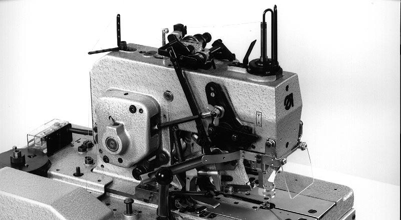
2 4. Malfunction Remedies Optional Equipment Electromagnetic Upper Thread Catcher General Electrical Connection Function Sequence Turn-on Interlocks Setting Lift of the Electromagnet Base Position of the Upper Thread Catcher Lowering Movement Gripping Movement Switches for the Upper Thread Catcher Controls Attachment Pre-assembling the Wiring Distributor Laying the Wiring Control Unit Mounting Switch b Mounting the Switching Rail for Switch b Mounting the Upper Thread Catcher on the Machine Arm The illustrations used in these instructions are of differing sub-classes of the buttonhole machine 558! Please note that your buttonhole may deviate from the illustrations!
3 1. Product Description 1.1 Short Description and Proper Use The DÜRKOPP ADLER 558 is a double chain stitch buttonhole machine. Buttonholes with or without eye and with or without taper bar can be sewn. The buttonhole form is determined by 2 exchangeable disc cams with corresponding knives. The upper disc cam determines the form of the eye. The disc cam lying thereunder determines for buttonholes with taper bar the taper bar form and the buttonhole length. The smallest and largest buttonhole width for each sewing device (E no.) is established by the position of the limit plate. Pendulum swing of the needle bar from the rest position one-sided to the right when sewing the right and one-sided to the left when sewing the left buttonhole seam. Automatic adaption of the upper cloth clamp pressure to differing material thicknesses through spring-hangered clamp frame. The safety devices do not have to be removed when tilting up the machine. The combined finger-eye protection device increases safety. It is held in the work position by springs. The gas pressure spring aids tilting up and effects a sure, slow lowering. The stop position makes an unhindered threading of the hook thread possible. The machine is equipped with a central oil wick lubrication from 2 oil reservoirs (the positions marked in red must also be oiled). In the next chapter the individual sub-classes are described. 5
4 1.2 Sub-classes With automatic trimmers. The upper thread, the underthread and the gimp fed in from the bottom are cut so short that no thread ends are visible. Cleaning is unnecessary. Cutting open the buttonhole after sewing. Cutting length 20 mm With automatic trimmers. The upper thread is cut off short. The underthread and the gimp fed in from the bottom are cut off long (about 30 mm). Cutting open the buttonhole depending on E no. before or after sewing, as desired. This sub-class has the electromagnetic upper thread catcher as standard equipment. Cutting length mm With automatic trimmer. Only the upper thread is cut short. The sewing piece can be easily removed from the sewing position or, with buttonholes lying in a row, simply pulled a bit to the left. The underthread and the lower gimp are then trimmed by hand. With this sub-class the sewing piece is positioned 12 mm further forward than with and Cutting open of the buttonhole, depending on the E no., as desired, before or after sewing. Cutting length mm The sewing piece is positioned 9.5 mm further forward than with sub-classes and This means a better view and more freedom when positioning the sewing pieces. With automatic trimmers. The upper thread, the underthread and the gimp fed in from the bottom are trimmed so short that no thread ends are visible. No cleaning is necessary. Cutting open the buttonhole after sewing. Cutting length dependent on the length package mm With automatic trimmer. Only the upper thread is cut short. The sewing piece can be easily removed from the sewing position or, with the buttonholes lying in a row, simply pulled a bit to the left. The underthread and the lower gimp are then trimmed by hand. Cutting open the buttonhole can be switched between cutting before or after sewing. Cutting length mm 6
5 1.3 Technical Specification Number of stitches: Stitches/min Type of stitch: Double chain stitch Sewing length: max. 50 mm Cutting length: max. 50 mm Needle system: 558 Needle thickness: Nm Depending on the type of sewing thread and the material. Looping stroke: mm Depending on the sewing device (E no.). Material thicknesses: max. 10 mm with sub-class max. 12 mm with all othersub-classes Sewing thread thickness: Upper thread max. Nm 50 Underthread max. Nm 30 Nominal voltage: ~ 400 V + N, 50/60 Hz ~ 230 V, 50/60 Hz ~ 230 V, 50 Hz ~ 230 V, 60 Hz The machine is delivered with one of the listed drive packages appropriate to the nominal voltage. Noise: Lc = 80 db (A) by sewing cycle 5.0 s on and 1.4 s off to DIN B-1 Dimensions: (H x W x D) 1570 x 630 x 520 mm (Standard) 1570 x 1060 x 520 mm (Wide model) Weight: 128 kg (complete with machine head, frame and motor) 55 kg (only frame and motor) Work height: mm (Top edge of table) 7
6 1.4 Sewing Devices The devices parts for the different buttonhole forms and cutting lengths are established under device numbers (E no. s). After the E no. behind a slash the cutting length or the setting range in mm is given. Example: 578 E2107 / 20 or 578 E209 / E209 / For sewing the various buttonhole lengths different cutting blocks, cloth clamps and disc cams are required. The appropriate order numbers can be found in the device sheet for the 558. The device summary table on the following page lists the currently available devices. The most suitable device for a specific buttonhole form and a certain type of material can be chosen quickly from the table. ATTENTION : For the 558 after July 1994 the device numbers for the 578 apply ( Chapter ). For the 558 up to June 1994 the device numbers for the 558 apply ( Chapter ). There are two different groups of buttonhole machines: Only cutting after sewing. Cutting before or after sewing as desired. For conversion of the buttonhole machine to a further buttonhole form or cutting length the following points are to be considered: 1. Only those parts are to be ordered and attached whose order numbers do not agree with those of the device available. See the device sheets for the 558 and the The cutting lengths can only be selected appropriate to the device or the setting range. By devices which have only one digit behind the slash the cutting length is not adjustable. 3. By machines which are switched over to cutting before or after sewing, the appropriate sections of these instructions are to be observed. 4. The setting values, buttonhole width and looping stroke, are interdependent and must be observed when changing to another device (E no.). If values deviating from the table arise, the adaption is to be made by a specialist as per the Service Instructions. 8
7 1.4.1 Device Summary Table and Function Characteristics 578 E... /... Buttonhole form Cutting Short trimmer Buttonhole Cutting Looping for width area stroke 558 Material before after min. max. mm mm mm mm Loose, coarse weave cloth E2107 / ---> N Upper thread, 4,5 5,8 0,4 2,7 20 Under th., Gimp Under thread, Gimp long 3,0 High quality clothing of E212 / E213 / V <-- ---> N " 5,0 7,0 - / 0,4 2,7 variing thicknesses Loose, coarse weave cloth Buttonholes similar to handworked E309 / ---> N Upper thread 4,1 5,2 0,4 3,0 quality in outerwear Small buttonholes in elastic material E311 / * ---> N " 4,1 5,2 0,4 3,2 (e.g. knitware) with round or flat gimp 6-34 Materials of variing quality and E312 / E312 / V < > N " 5,0 7,0 - / 0,4 2, thickness Garment leather E327 / V < > N " 5,0 7,0 - / 0,6 3, Waistbands on jeans, E328 / ---> N " 4,5 5,8 0,4 3,0 graduated cloth clamps Fine, tightly woven materials E334 / V <--- " 6,0 7,0-2,7 (e.g. poplin) * The construction set upper gimp guide must be ordered additionally. 9
8 Buttonhole form Cutting Short trimmer Buttonhole Cutting Looping for width area stroke 558 Nähgut before after min. max. mm mm mm mm Loose, coarse weave cloth E2407 / ---> N Upper thread, 4,5 5,8 0,4 2,7 L1 - L3 Under th., Gimp Buttonholes in elastic material (e.g. knitware) Waistbands on jeans and similar E2417 / ---> N " 4,5 5,8 0,4 3,0 L1 - L3 Loose, coarse weave cloth, E2431 / ---> N " 4,5 5,8 0,4 2,7 plastic stitch formation L1 - L Materials of variing quality and E512 / E512 / V < > N Upper thread 5,0 7,0 / 0,4 2,7 thickness
9 1.4.2 Device Summary Table and Function Characteristics 558 E... /... Buttonhole form Cutting Short trimmer Buttonhole Cutting Looping for width area stroke 558 Material before after min. max. mm mm mm mm Loose, coarse weave cloth E107 / ---> N Upper thread, 4,5 5,8 0,4 2,7 20 Under th., Gimp Under thread, Gimp long 3,0 High quality clothing of E212 / E213 / V <-- ---> N " 5,0 7,0 - / 0,4 2,7 variing thicknesses Loose, coarse weave cloth Buttonholes similar to handworked E309 / ---> N Upper thread 4,1 5,2 0,4 3,0 quality in outerwear Small buttonholes in elastic material E311 / * ---> N " 4,1 5,2 0,4 3,2 (e.g. knitware) with round or flat gimp 6-34 Materials of variing quality and E312 / E312 / V < > N " 5,0 7,0 - / 0,4 2, thickness Garment leather E327 / V < > N " 5,0 7,0 - / 0,6 3, Waistbands on jeans, E328 / ---> N " 4,5 5,8 0,4 3,0 graduated cloth clamps Fine, tightly woven materials E334 / V <--- " 6,0 7,0-2,7 (e.g. poplin) * The construction set upper gimp guide must be ordered additionally. 11
10 Buttonhole form Cutting Short trimmer Buttonhole Cutting Looping for width area stroke 558 Nähgut before after min. max. mm mm mm mm Loose, coarse weave cloth E407 / ---> N Upper thread, 4,5 5,8 0,4 2,7 L1 - L3 Under th., Gimp Buttonholes in elastic material (e.g. knitware) Waistbands on jeans and similar E417 / ---> N " 4,5 5,8 0,4 3,0 L1 - L3 Loose, coarse weave cloth, E431 / ---> N " 4,5 5,8 0,4 2,7 plastic stitch formation L1 - L Materials of variing quality and E512 / E512 / V < > N Upper thread 5,0 7,0 / 0,4 2,7 thickness
11 1.5 Optional Equipment Electromagnetically operated upper thread catcher The electromagnetically operated upper thread catcher immediately after the thread trimming procedure grips the upper thread. It holds this clamped and inserts it in the right seam during sewing of the next buttonhole. This means: Secure seam beginning even with light, loose cloth. Beginning stitches pulled tight. Neating the underside of the buttonhole is unnecessary because the beginning thread is sewn over. The sub-class has the upper thread catcher as standard equipment. It is available on request for all other sub-classes Thread oiler For improving thread glide in extremely thickness material Gimps roller holder on the table top For lower Gimps which are stiff and hard to bend Thread unreeler, complete For holding thread or wool cones. The attachment is to the middle traverse of the table frame Stop for buttonhole interval from mm App Halogen sewing light App Mounting kit Sewing light transformer Stops for the clearance between material edge and buttonhole are available in different lengths on request. 13

12
13 2. Operation 2.1 Removal and Placement of the Clamp Plates Caution Risk of Injury! Pull the mains plug. Remove or place the clamp plates only with the machine turned off. The removal or placement of the clamp plates 3 and 5 occurs in the machine end position (see Chapter 2.3). The clamp operating lever 1 must be open! This is the case when it is pushed to the back until it hits. ATTENTION! In order to avoid damage to the needle the combined finger-eye protection 4 must remain swung down. Sub-class and : Removing the clamp plates Swing the clamp plate holder 2 away to the side. Reach under each nail slit 6 and lift the clamp plate. Remove the clamp plates to the front. Placing the clamp plates The clamp operators 8 must reach into the forks of the clamp arms. Push the clamp plates to the right or left against the pressure screws 7 and plate edges 9. Place the clamp plates over the setbolt 10 on the material support plate. Swing the clamp plates holder 2 back over the clamp plates. The clamp plates are secured against lifting. Check by closing the clamp operating lever 1 if the clamps open and close correctly. 15


14 und

15 Sub-classes , and : Removing the clamp plates Swing the clamp plate holder 1 away to the side. Pull the spring mounted slide 3 in the direction of the arrow and remove the right clamp plate. Reach under the nail slit 2 and remove the left clamp plate. Placing the clamp plates Place first the left, then the right clamp plate. The clamp operators 5 must reach into the forks of the clamp arms. Push the clamp plates to the right or left against the pressure screws 4 and plate edges 6. Place the clamp plates over the setbolt 7 on the the material support plate. Hereby pull the spring mounted slide 3 in the direction of the arrow and let catch in groove 8. Swing the clamp plate holder 1 over the clamp plates again. The clamp plates are secured against lifting. Check by closing the clamp operating lever if the clamps open and close correctly

16 1 2 18
17 2.2 Turning On - Quick Stop - Restart Caution Risk of Injury! Do not reach into the area of moving machine parts, particularly not under the knife and the cloth clamps. Turning on Turn on the drive motor with the hand shift lever 1. Loosen the hand shift lever 1 out of its catch by pulling up on the ball head and bring into position "I". The catch prevents an unwanted turning on of the drive motor. Turning off Turn off the drive motor, as desired, with the hand shift lever 1 or the pedal 2. Place the hand shift lever 1 in position "0". The hand shift lever catches in this position. Step forward on pedal 2. Caution Risk of Injury! As long as the operator is not yet familiar with the machine, she should turn off the motor with the pedal or hand shift lever after sewing each buttonhole. restarting should occur only after the cloth has been repositioned and the clamp are closed. Quick stop The safety system of the 558 has two possibilities for an immediate stop during the sewing process by operating errors or malfunctions (e.g. needle or thread breakage): Put the hand shift lever 1 in position "0". Step pedal 2 forward. 19

18
19 Restart In order to avoid damage to the machine, when restarting after a quick stop it is essential to proceed as follows: Lift the idle lever 5 until it jumps off of the nose 4 of the length setting slide 6. Attention! This point is only to be carried out if the machine was turned off immediately after the first sewing stitches. Pull the turn-off lever 1 forward. ATTENTION! Before turning on the machine always bring the needle into the high position by catching in the handwheel 3. A bending of the needle or damage to the material is thus avoided. Exception: The handwheel may not, however, be turned at that moment in which, after the end of the sewing sequence, the cutting movement of the upper thread knife begins and this lies under the needle hole of the needle plate. Turn the handwheel 3 in the direction of the arrow until it catches. The handwheel is arrested in this position by brake lever 2. The needle is in its highest position. Open the clamp plates and remove material. Close the clamp plates again. Turn on the machine with the hand shift lever. The material support plate moves to its end position. The needle remains in its highest position. ATTENTION! Only turn the hand crank of the high-speed wheel when the handwheel has caught in the direction of turn. 21
20 1 2 22

21 2.3 End Position of the Sewing Machine Turn handwheel 2 until it catches. The needle is in its highest position. ATTENTION! Before turning the hand crank it is essential that the needle be brought into its high position by moving the handwheel into its catch. A bending of the needle or damage to the material is thus avoided. Exception: The handwheel may not, however, be turned at that moment in which, after the end of the sewing sequence, the cutting movement of the upper thread knife begins and this lies under the needle hole of the needle plate. Turn the hand crank until the clamp closing lever 1 automatically opens the clamp arms. Depending on the setting of the machine to cutting before or after sewing opening occurs before or after operation of the cutter bar 3. The machine is in the end position. 3 23

22 2.4 Needles, Threads and Gimps 1 2 Table: Threads and Gimps Sub-class Needle thread type and thickness Hook thread type and thickness Lower gimp type and thickness Polyester fiber thread, schappe-spun 70/3 Polyester fiber thread, schappe-spun 70/3 Tube or wire gimp Polyester fiber thread, schappe-spun 70/3 Polyester fiber thread, schappe-spun 30/3 not required Upper gimp type and thickness not required Twist gimp 15/3 24
23 Needles Needle system: 558 Needle thickness: Nm Dependent on type of sewing thread and material. Replacing the needle Caution Risk of Injury! Pull the mains plug. Replace the needle only with the machine turned off. Swing up the combined finger-eye protection. The needle is accessable without hinderance. Loosen screw 1 and remove the needle. Push the new needle as far as possible into the hole in the needle bar 2. Attention! The furrow of the needle must show to the front with the machine in its end position. Tighten screw 1 again. Swing the combined finger-eye protection back again. Threads As needle and hook thread, spun, synthetic fiber thread or silk thread can be used. The appearance of the buttonhole is considerably influenced by the thread used. the use of different strengths for needle and hook thread. Gimps The gimp should stabilize the buttonhole and at the same time by it form. It should have the following characteristics: not too thick, but pliable and firm uniform diameter The recommended threads and gimps in the table alongside are only guide lines. Dependent on sewing device (E no.) and material other threads and thread thicknesses may also be required. 25


24 a b c e d c 26
25 2.5 Threading of the Underthread (Hook Thread) Caution Risk of Injury! Pull the mains plug. Thread the underthread only with the machine turned off. The threading of the underthreads 1 (Page 28) is conducted as shown in the illustrations on pages 26 and 28 in alphabetical order of the letters: Bring the machine in its end position (see Chapter 2.3). In the end position the hook bracket with the underthread tension must point to the front (to the seamstress). Remove the clamp plates (see Chapter 2.1). Tilt up the machine head. The gas pressure spring aids the tilting and holds the machine head in its position. Place the thread spool on the thread stand and guide the thread through hole a. Guide the thread through the thread guide b in the thread guide tube c on the back of the housing. Guide the thread through the thread guide tube d. Guide the thread with the aid of the threading wire from the accessories pack into the spreader drive spindle e. For this insert the threading wire into the spreader drive spindle from above. Lead the thread over the guide pin f and past behind the tension plate g. Lead the thread between the two tension discs of the underthread tension h up over the guide pin i. Guide the thread through the eye of the torsion spring k. With sub-classes , and additionally guide the thread through the hole of the bring-forward lever l. Lead the thread up through the thread guide tube m. Lead the thread through the spreader stop n. Guide the thread from below through hole o in the hook and needle hole p of the needle plate. Hereby let an approx. 25 mm long underthread end hang out of the needle hole. 2 = Gimp thread (Page 28) 27
26 m k l f i g h 1 2 p o n 28
 underneath the table. Lead the thread through the thread guides under the table. Lead the thread up through the thread tube.")
27 Path of the underthread when using yarn or wool cones: If yarn or wool cones are used as hook thread then these are to be set on the as optional equipment available thread unreeler 1 (Order no ) underneath the table. Lead the thread through the thread guides under the table. Lead the thread up through the thread tube. The threading of the machine above the table is conducted as described above. 1 29


28 a
29 2.6 Threading the Gimp Caution Risk of Injury! Pull the mains plug. Thread the lower and upper gimp only with the machine turned off. Place tube and wire gimp rolls on the gimp roll holder 1. Place the gimp rolls with crosswinding vertically on the yarn plate 2 for an easy pull off of the gimp or thread. For stiff and difficult to bend lower gimps choose the short feed over the as optional equipment available gimp roll holder 3 (Order no ). Lower gimp threading The threading of the lower gimp is conducted as shown in the lllustrations on pages 30, 32 and 33 in the alphabetical order of the letters: Sub-classes , , and : Remove the clamp plates (see Chapter 2.1). Thread the gimp from the gimp roll holder 1 or the yarn plate 2 through hole a in the thread stand. Lead the gimp in order through the gimp guide b and the gimp guide tubes c and d. Thread the gimp through gimp guide e. With sub-class the gimp must also be threaded through the draw spring f. Through the draw spring the loosening gimp thread is held taut during simultaneous turning movement of the hook bracket and operation of the gripper knife. Thread the gimp through the gimp hole g of the needle plate. Allow an approx. 25 mm long gimp end to hang out of the gimp hole. 4 = Hook thread (Page 32) 5 = Gimp thread (Page 32) Replace the clamp plates again (see Chapter 2.1). 31
30 b c d 4 5 e f g 32
. Turn the hand crank drehen until the hook bracket reaches the position shown.")
31 Sub-class : This sub-class is equipped with gimp pulling device. Before the start of sewing it pulls the gimp back to the correct starting length. For correct positioning see the Service Instructions. Remove the clamp plates (see Chapter 2.1). Turn the hand crank drehen until the hook bracket reaches the position shown. The gimp pulling device 1 faces forward (to the seamstress). Lead the gimp 2 from the lower gimp roll holder 4 through the side recess a in the machine housing. 3 = Hook thread Thread the gimp through the holes of the gimp pulling device 1. For threading through the hole b press the brake flap 5 lying behind a little to the back. Thread the gimp 2 through the holes of the gimp guide c and gimp hole d of the needle plate. With the gimp pulling device in low position let an approx. 4 mm long gimp end look out of the gimp hole of the needle plate. Replace the clamp plates again (see Chapter 2.1) d c 5 4 a b 1 33


32 a b c d f e 34
33 Upper gimp threading The feed of the upper gimp is possible with a gimp guider placed in front of the needle. The threading of the upper gimp is conducted as shown in the illustrations alongside in the alphabetical order of the letters: Thread the gimp from the gimp roll holder a through gimp guide b. Lead the gimp through the gimp guide angle c and between the tension discs of the gimp pre-tensioning d. Thread the gimp through the gimp guide e and the gimp guider f. The assembly for round and flat gimps is available under the Order no.:


34 a b d i h 1 g e c f 2 36
35 2.7 Threading of the Upper Thread (Needle Thread) Caution Risk of Injury! Pull the mains plug. Thread the upper thread only with the machine turned off. The threading of the upper thread is conducted as shown in the illustrations on pages 36 and 38 in the alphabetical order of the letters: Bring the machine into its end position (see Chapter 2.3). In the end position the hook bracket with the underthread tension must face forward (to the seamstress). Close the clamps with the aid of the clamp operating lever and swing up the combined finger-eye protection. The needle bar and needle are accessable unhindered. Place the thread spool on the thread stand and guide the thread through hole a. Guide the thread in order through the thread guide b and under thread guide c. Lead the thread between the tension discs d of the upper thread tension and over guide pin e. Guide the thread through the hole of the lever f and the thread lever g. Lead the thread through the thread gripper h and thread guide i. Guide the thread with the aid of the threading wire from the accessories pack through needle bar k. Lead the thread past behind the tension disc of the pre-tensioning l and through the eye of the needle. Subsequent pulling of the upper thread by hand The upper thread is trimmed after the last stitch automatically. For subsequent pulling of the upper thread: Operate the release lever 2 or push button 1 and subsequently pull the upper thread by hand. 37


36 k l 38

37 Threading by difficult to unreel thread rolls To achieve an easy pull off of the upper and underthread from the thread plate: Additionally guide the underthread through the holes 1 and 2. Additionally guide the upper thread through hole

38
39 2.8 Thread Tension Upper thread tension The upper thread tension on the machine arm must generally be set tighter than the underthread tension. It is set by turning the knurled nut 6. Tension increase = turn to the right Tension decrease = turn to the left The upper thread tension is executed as a dual tension: Remaining rest tension 1 It serves to tauten the upper thread during the cutting procedure under the needle plate as well as to achieve the desired length of upper thread end. The rest tension must, depending on the elasticity of the upper thread used, be so set that upper thread end hanging out of the needle is long enough to assure a secure sewing start. The setting occurs by turning the sleeve 2. Longer thread end = turn to the left Shorter thread end = turn to the right ATTENTION! Do not heighten the cutting effect of the upper thread knife by further increasing the rest tension. To heighten the cutting effect sharpen the knife. If the upper thread end remains too long then work must be conducted without tension release. This can, for example, be the case with firm and hardly flexible upper thread. For the appropriate settings see Service Instruction 558. Main tension 5 This should be appropriately corrected after changing the rest tension. The thread gripper 3 remains closed in the end position. During removal of the sewing pieces this avoids a subsequent pulling of the upper thread out of the thread tension. For the next sewing sequence there is then always an uniformly long starting thread available. Subsequent pulling of the upper thread by hand Open the thread gripper 3 by hand and subsequently pull the thread. For this either hold the button 4 down or swing the release lever 7 down. 41
40
41 Underthread tension The underthread tension is set by turning the knurled nut 3 on the hook bracket. Tension increase = turn to the right Tension decrease = turn to the left Thread pull-on spring for the underthread The thread pull-on spring 1 influences the pull-on of the underthread through its stopper width and pre-tension and thus the form and beading of the buttonhole. Setting the stopper width: Loosen screw 5 and turn the angle 4. Setting the pre-tension: Loosen screw 6 and turn angle 2. Gimps The upper and lower gimp should be pulled easily and uniformly from the guide hole in the needle plate and the gimp guider. For a faultless appearance of the buttonhole a braking or clamping of the gimp on its way to the sewing station is to be avoided. 43

42
43 2.9 Sewing Place a work piece under the clamps and align precisely. The alignment can be made with markings or the stops available as optional equipment (see Chapter 1.5). Caution Risk of Injury! Keep hands out from under the lowering cloth clamps! Pull the clamp operating lever 1 to the front until it touches. The work piece is fixed by the clamps. Turn on the motor with hand shift lever 3. For this loosen the hand shift lever out of its catch by pulling up on the ball head and bring into position "I". Press start lever 2 down. The machine, depending on setting, automatically conducts the following work steps in order: With the setting "cutting before sewing": The cutting knife cuts the buttonhole slit. The material support plate moves quickly with the clamped in work piece so far forward until the beginning of the buttonhole slit is exactly under the needle. At the same time the clamp plates are drawn apart. The buttonhole slit is opened a little. The sewing unit is turned on and the buttonhole sewn. After the left seam row is completed the needle stops outside the cloth. The material support plate moves quickly to its end position, thereby opening the clamps. With the setting "cutting after sewing": The material support plate moves quickly with the clamped in work piece so far forward until the position where the buttonhole is to start is exactly under the needle. At the same time the clamp plates are drawn apart. The cloth lies taut for the sewing of the buttonhole. The sewing unit is turned on and the buttonhole sewn. After the left seam row is completed the material support plate moves quickly in the cutting position. The buttonhole slit is cut. The material support plate moves quickly to its end position, thereby opening the clamps. 45
44
45 Caution Risk of Injury! As long as the seamstress is not yet familiar with the operation of the machine she should turn off the motor with the hand shift lever 3 or the pedal after sewing each buttonhole. Work procedure for the experienced seamstress After a suitable learning period the closing of the clamp operating lever 1 and the turning on and off of the motor with every buttonhole through the seamstress can be eliminated. Instead the experienced seamstress proceeds as follows: Place the work piece exactly under the clamps by eye or with stops and hold the cloth fixed in this position. Caution Risk of Injury! Keep hands out from under the lowering cloth clamps! With the left index finger press the start lever 2 down. The machine closes the clamps by itself and runs through all described work procedure automatically. Taking out the finished work piece If necessary a little subsequent pulling of the upper gimp and then trimming. The work piece can be pushed further or removed. For removal of work pieces with sub-classes and Guide the underthread (hook thread) and lower gimp under the thread gripper 5. Pull both threads from right to left along the knife 6. The threads are trimmed Blocking the Clamp Lift Normally, after the ending of the sewing process the clamps are automatically lifted (opened). If they should not be lifted, proceed as follows: Push button 3 immediately and hold pressed until the machine shuts off. 47

46
47 2.11 Buttonhole length Caution Risk of Injury! Pull the mains plug. Set the buttonhole length only with the machine turned off. ATTENTION! The changing of the buttonhole length requires a simultaneous change of the cutting length and thus the mounting of a different cutting block (see Chapter 2.12)! Buttonholes without Taper Bar By buttonholes without taper bar the buttonhole length is determined through the position of the length setting slide 3: Loosen clamp screw 4. Set the desired buttonhole length. Longer buttonhole length = Pull the length setting slide 3 forward Shorter buttonhole length = Push the length setting slide 3 to the rear The scale 1 and marking lines 2 serve for setting a specific buttonhole length. Tighten clamp screw 4 again. ATTENTION! Set only the through the sewing device (E no.) allowable minimum and maximum buttonhole lengths. Sub-classes and : With these sub-classes an exceeding of the maximum sewing length is prevented by a stop. With the setting of the length setting slide at max. sewing length the stop piece must lay in at the guide slit at the front. ATTENTION! Scale plate, length setting slide and stop piece have been correctly set at the factory. They may not be altered. 49

48 1 Example: E407/L2 resp. E2407/L2 Sewing length Cutting length Taper bar length minimum Sewing length maximum Sewing length Sewing length 50
49 Buttonholes with Taper Bar By buttonholes with taper bar the different buttonhole lengths are achieved through insertion of the appropriate lower disc cam 1. It determines taper bar form and length. For exchanging the lower disc cam see Chapter The order numbers for the different lower disc cams can be found on the device sheets for the 558 and 578. The shortening, lengthening or complete shutting off of the taper bars occurs as described above through adjusting the length setting slide and mounting of the corresponding cutting block. ATTENTION! Do not set the taper bar length below the minimum or beyond the maximum buttonhole length. When setting the length of buttonholes with taper bar along with the cutting length the taper bar length must also be added in. Example: 18 mm cutting length + 4 mm taper bar length = 22 mm sewing length Special characteristic by sub-class : With this sub-class buttonhole length, cutting length and taper bar length can be changed. For this four different cutting length packages (L1...L4) can be requested: L1 for cutting lengths of mm L2 for cutting lengths of mm L3 for cutting lengths of mm L4 for cutting lengths of mm Each cutting length package includes: 3 lower disc cams and cutting blocks for sewing buttonholes with 3 different cutting lengths a corresponding clamp plate set The clamp plate sets are differentiated by differing lengths for cloth clamps and thread scissors with operating element for the short trimming of thread. In order to assure a secure gripping and short trimming of thread and gimp the difference in the buttonhole lengths which can be sewn with one cutting length package cannot exceed 2 mm. Example: 578 E 2407/L2 (Sewing device E2407 combined with cutting length package L2) Allowable sewing lengths: minimum 24 mm maximum 26 mm. 51


50
51 2.12 Cutting Length The cutting length is determined by the length of the cutting block. It can be altered by changing the cutting block. The order numbers for the different cutting blocks are, taking into account the sewing device used (E no.), to be found on the device sheets for the 558 or 578. Changing the cutting block Caution Risk of Injury! Pull the mains plug. Change the cutting block and cutting knife only with the machine turned off. Cutting block 3 and cutting knife 4 are designed so that two configurations are possible: Configuration top (on cutter bar 1) Configuration bottom (below the clamp plates on the anvil body 6) To change the cutting block: Loosen screw 2 or 8 and remove the cutting block or cutting knife entfernen. Insert the new cutting block and cutting knife and tighten screws 2 and 8 again. Attention! When inserting push the new cutting block to the back until touching on the stop 5 or 7. ATTENTION! Insert only the cutting blocks corresponding to each cutting knife. Cutting knife for "cutting before sewing" have a larger eye form than a cutting knife for "cutting after sewing". In order to avoid having two different knife impressions on one cutting block the cutting block corresponding to the cutting knives must always be inserted. Cutting knives with two different knife impressions cause buttonholes to not be cleanly cut and must be trued again (see Chapter 2.13). 53


52
53 Mounting the cutting block at the top or bottom? The mounting of the cutting block 2 and the cutting knife 1 is dependent on the sub-class with its sewing device (E no.) for cutting "before" or "after sewing": A. Sewing device for "cutting before sewing": Cutting block at bottom and cutting knife at top The material is supported by the cutting block during the cutting procedure. In this way an unwanted pressing down of the edges of the buttonhole slit by thick material (as in configuration b) is avoided. Attention! With the cutting knife mounted at the top the waste pipe 3 for collection of cutting waste must be mounted on the cutter bar 4. B. Sewing device for "cutting after sewing": Cutting block at the top and cutting knife below The sewn buttonhole seam glides down the slim sides of the cutting knife without resistance during the cutting procedure. In this way an unwanted deformation through pressure exerted on the buttonhole seam (as with configuration a) is avoided. C. Sewing device for "cutting before and after sewing": Cutting block at the top and cutting knife below Exception: With the setting "cutting before sewing" and at the same time processing of thick material the reverse configuration (cutting block at the bottom and cutting knife above) is to be chosen. In this way an unwanted pressing down of the edges of the buttonhole slit (as with configuration b) is avoided. ATTENTION! For the change-over from "cutting before sewing" to "cutting after sewing" it is essential to obderve Chapter

54
55 2.13 Cutting Blocks Caution Risk of Injury! Pull the mains plug. Remove the cutting block only with the machine turned off. A trueing (filing) of the cutting block becomes necessary, when the cutting block has been too strongly cut into by the cutting knife. when two different cutting knife forms have worked on the cutting block (Illus. 2). When trueing the cutting block care is to be taken: The cutting block must be so filed that the impression of the knife blade is to be seen everywhere very fine and exactly uniform ( Illus. 1). ATTENTION! The trueing of the cutting block must be conducted very precisely. Use only flawless, straight bastard files! The height of the cutting blocks may only be reduced by a maximum 1.5 mm through filing. To achieve a uniform distribution of the cutting pressure the cutting block must hit parallel onto the cutting knife (see sketch). One-sided cutting pressure, particularly in the area of the eye, can cause the cutting knife to break off. Illustration 1 shows a correctly filed, illustration 3 a badly filed cutting block. After trueing one cutting block, all other cutting block used must also be reworked to the same height dimension. Only in this way can, after a cutting block change, work continue with the same cutting pressure. Otherwise there is a danger of breaking the cutting knife by a change of the cutting block! Malfunctions during cutting After a longer period of operation the sharpness of the cutting knife is reduced. The blade is blunt and the knife no longer cuts precisely in spite of a correctly trued cutting block. Send the knife to one of the DÜRKOPP ADLER AG for reworking. 57

56 2.14 Cutting Pressure 1 The cutting pressure is set with screw 1: Increase cutting pressure = turn to the right Decrease cutting pressure = turn to the left After each adjustment of screw 1 the cutting pressure must be checked. Checking the cutting pressure Turn the machine with the hand crank. The cutting pressure may only be set so high that the hand crank can be turned at the moment of cutting without exerting too much energy! ATTENTION! Excessive cutting pressure leads to unnecessary wear of the cutting tools! If even with this setting of the cutting pressure the cloth can still not be cleanly cut: True the cutting block or check the sharpness of the knife blade (see Chapter 2.13). 58

57 2.15 Spreading of the Material Caution Risk of Injury! Pull the mains plug. Set the spreading only with the machine turned off. At the setting "cutting after sewing" the clamp plates are drawn apart after the run start of the material support plate. The material is drawn taut. At the setting "cutting before sewing" the clamp plates are drawn apart only after the cutting. The buttonhole slit is opened a little. The stitching needle can cleanly sew both seam rows without stitching into the cut edge of the material. Normally a spreading of 1.5 mm is sufficient. Remove the clamp plates (see Chapter 2.1). Loosen screws 1 and 3 and move the stops 2 and 4. Increase spreading = move the stops inward Decrease spreading = move the stops outward ATTENTION! So that both seam rows are equally wide the left and right stops must be moved equal distances. Tighten screws 1 and 3 again. With unequal seam widths correct the spreading accordingly 59


58 A B 1 2 A 3 B 4 60
59 2.16 Stitch Density Caution Risk of Injury! Pull the mains plug. Set the stitch density only with the machine turned off. For the whole buttonhole length The stitch density is adjustable between 0.9 and 2 mm. It is determined by the required strength and the appearance of the buttonhole, as well as the thread size used. Loosen screw 2. Move the transport lever 1. Movement in direction A = stitches become denser Movement in direction B = stitche are farther apart Tighten screw 2 again. In the eye of the buttonhole This setting has no influence on the stitch density in both seam rows. Stitch density in the buttonhole eye to be smaller: Loosen screw 4. Move the stitch length regulator rail 5 in the direction of the arrow. Tighten screw 4 again. Stitch density in the buttonhole eye to be greater: Loosen screw 4. Replace the old stitch length regulator rail 5 with the stitch length regulator rail 3 found in the accessories pack. Tighten screw 4 again
60 B A Seam width Cutting area Buttonhole width 62
61 2.17 Seam Width (Buttonhole Width) Caution Risk of Injury! Pull the mains plug. Set the seam width only with the machine turned off. At the setting "cutting after sewing" the buttonhole width is arrived at as follows: Buttonhole width = Cutting area + 2 x seam width Setting the seam width Loosen the wing nut 2. Move the connecting rod 3. Movement in direction A = wider seam Movement in direction B = narrower seam Tighten the wing nut 2 again. Setting for sewing with gimp thread Select the seam width so that the gimp thread is not pierced by the needle tip but rather just still overcast. Smallest and greatest allowable seam width The smallest and greatest allowable seam width for the sewing device used (E no.) is determined by the limit plate attached with screw 1. ATTENTION! Do not loosen screw 1 under any circumstances. There is a danger of breakage for the needle, cloth clamps, hook, spreader and needle plate! Should the machine be converted to another sewing device (E no.) umgerüstet werden, then the allowable buttonhole widths for it are to be found in the table in Chapter 1.4. The conversion is to be made per the Service Instructions. 63

62
63 2.18 Buttonhole Form The buttonhole form is determined by the two exchangeable disc cams 1 and 2: The upper disc cam 1 determines the eye form. The lower disc cam 2 determines, by taper bar buttonholes, the taper bar form and buttonhole length. Disc cams, cutting blocks and cutting knife for the different buttonhole forms and buttonhole lengths are to be found in the device sheet for the 558 and 578. Exchanging the disc cams Bring the machine into the end position (see Chapter 2.3). In the end position the roller bolt 4 is held in position by the underlying cam plate 3. The disc cams can be removed unhindered. Remove and exchange the disc cams. After the exchange of the disc cams it is essential that the following points be checked: 1. Are the corresponding cutting knife and the appropriately long cutting block mounted? If necessary exchange the cutting knife and cutting block (see Chapter 2.12) 2. Is the correct buttonhole length set as per Chapter 2.11? If necessary set the correct buttonhole length at the length setting slide (see Chapter 2.11). 3. During the exchange of the knives was the corresponding cutting block also mounted? ATTENTION! When changing to a different cutting knife form it is essential to also install the corresponding cutting block! When using the wrong cutting block two differing cutting knife impressions appear in it. This leads to a bad cutting of the buttonhole slit. In this case true the cutting block again (see Chapter 2.13). 65

64 1 2 66
65 2.19 Change-over to Cutting Before or After Sewing Caution Risk of Injury! Pull the mains plug. Conduct the change-over to "cutting before" or "cutting after sewing" only with the machine turned off vornehmen. The change-over from "cutting before" to "cutting after sewing" is only possible with sub-classes with the appropriate sewing device (E no.) (see Device Table in Chapter 1.4). All machine elements which must be adjusted are marked by the following bi-lingual sticker with the following meaning: Adjustment in direction of arrow = cutting before sewing Adjustment in direction of arrow = cutting after sewing Note: CA and CB are the English language abbreviations. CA = Cut after CB = Cut before Change-over to "cutting before" or "cutting after sewing" The settings for cutting before and cutting after sewing are each limited by two stops. ATTENTION! The stops have been set. They may not be altered! 1. Timing of the cut Loosen screw 2. Slide the turn-off bolt 1 in the appropriate arrow direction. Press the high-speed wheel inward for easier setting of the turn-off bolt. Tighten screw 2 again. 67

66
67 2. Timing of the closing and opening of the clamps Tilt the machine head up. Loosen screw 2. Push the clamp closing lever 1 in the appropriate arrow direction up to the stop. Tighten screw 2 again. 3. With or without cutting room between the seam rows Loosen screws 5. Slide the lever 4 in the appropriate arrow direction up or down up to the stop. Attention! The amount that the lever has to be moved is very small. Tighten screws 5 again. 4. Cutting knife and cutting block Slide the cutting knife 4 in the appropriate arrow direction up to the stop. The configuration of the cutting at the top or below occurs hereby as per the instructions in Chapter Insert the cutting block 3 corresponding to the cutting knife used and slide to the back up to the stop (see Chapter 2.12). ATTENTION! Only mount the cutting block corresponding the cutting knife used! When using the wrong cutting block two different cutting knife impressions are made. This leads to a bad cut of the buttonhole slit. 5. Exchanging the upper disc cam (see Chapter 2.19) Bring the machine in its end position bringen (see Chapter 2.3). In end position the roller bolt is held in its position by the underlying cam plate. The upper disc cam can be removed unhindered. Remove and exchange the upper disc cam. 69

68 3. Maintenance 1 Caution Risk of Injury! Pull the mains plug. Maintain the machine only when it is turned off. 3.1 Cleaning A clean machine protects against malfunctions! Daily cleaning: Clean the area under the clamp plates, particularly around the hook bracket 1, of sewing dust, thread rests and cutting refuse. ATTENTION! It is to be avoided that cutting refuse enters into the housing of the main disc cam at the back. If a vacuum is available this is recommended. Take off the clamp plates (see Chapter 2.1) and remove cutting waste. Tilt up the machine head and remove cutting waste from the base. 70

69 3.2 Lubrication 1 2 For lubrication of the machine only ESSO SP-NK 10 lubricating oil is to be used. SP-NK 10 is available at the DÜRKOPP ADLER AG sales offices. Check the oil level in the oil reservoirs The lubrication of all moving parts the machine on the machine arm and hook bracket is through a central oil wick lubrication out of the oil reservoirs 1 and 2. If necessary fill oil through the filling plug up to the "max." marking. Weekly lubrication of the buttonhole machine The marked positions on the material support plate and the control curve housings are to be given a few drop of oil weekly. The positions are shown in the pictures on the following page. 71


70 3.3 Oiling Positions * * * * * * * * * * * 72


71 * * * * * * * * * * * * * 73


72 * * * * * * * 74

73 * * 75
74 4. Malfunction Remedies Malfunction Remedy 1. Machine does not start or runs unevenly. a) V-belt from the motor to the high-speed wheel or to the handwheel is too loose. b) Machine is in front of the cutting position at the time of starting. Tension V-belt as per Installation Instructions for the 558. With the main witch turned off and the needle high bring the machine into its end position with the hand crank. Reduce cutting pressure as per Chapter Clamp closing lever cannot be closed or opened. Material support plate is not in the end position. With the hand crank bring the material support plate into the end position. With a repeat of this malfunction have a specialist reset the turn-off timing (see Service Instructions for the 558). When changing over to cutting before or cutting after sewing always slide the turn-off bolt up to the stop. 3. Cloth clamp pressure is too high or too low. 4. Buttonhole is not cleanly cut open. a) Cutting block has been cut into too deeply by the knife. b) Knife blade is blunt or broken. c) Exit opening in the knife is blocked by cloth waste. d) Cutting pressure is not correctly set. e) The cutting block corresponding to the cutting knife is not mounted. Reset the cloth clamp pressure (see Chapter 2.17). True the cutting block (see Chapter 2.13) and reset the cutting pressure (see Chapter 2.14). Insert a new knife or send the old knife to one of the DÜRKOPP ADLER AG business offices for reworking. Remove the knife and clean the exit opening in the knife and knife holder or cutter bar. Reset the cutting pressure (see Chapter 2.14). Always mount the cutting block corresponding to the cutting knife used! 76
75 Malfunction Remedy 5. Unequal stitch lengths or stitch positions. a) V-belt is too loose. b) Gimp is too taut, jams or does not pass easily through the gimp hole of the needle plate. 6. Missing stitches a) Needle is blunt, bent or not correctly inserted. b) Upper or underthread is not correctly threaded. c) Thread tension is set too taut. d) Thread unwinds badly from the thread rolls. e) Hook or spreader have become misadjusted. f) Material is not held or spread correctly. 7. Loose stitches. a) Thread tensions are not set correctly. b) Upper or underthread is not threaded correctly. 8. Thread breakage. a) Upper or underthread is not threaded correctly. b) Needle is incorrectly inserted, bent or sharp-edged. c) Thread used is unsuitable (knotted, hard or too thick). d) Thread tensions are set too taut. e) Needle plate, hook or spreader are damaged. Tension V-belt as per Installation Instructions for the 558. Use thinner gimp or insert a needle plate with larger gimp hole. For stiff and inflexible gimps use gimp roller holder on the table (Order no ). Insert a new, flawless needle (see Chapter 2.4). Check the threading path of the upper or underthread (see Chapter 2.5 and 2.7). Reset thread tension (see Chapter 2.8). See Chapter 2.7. Readjustment only through a specialist! Check the spreading of the material (see Chapter 2.17) and pressure of the upper cloth clamps. Reset thread tensions (see Chapter 2.8). Check the threading path of the upper or underthread (see Chapter 2.5 and 2.7). Check the threading path of the upper or underthread (see Chapter 2.5 and 2.7). Insert a new, flawless needle (see Chapter 2.4). Use a different thread. See recommendations in Chapter 2.6. Reset thread tensions. (see Chapter 2.8) Replace damaged parts through new ones or have reworked by a specialist. 77
76 Malfunction Remedy 9. Needle breakage. a) Needle thickness is unsuitable for the material or the thread. b) Needle is hitting the cloth clamps. 10. No clean seam beginning or unthreading of the upper thread. a) Rest tension for the upper thread is set too taut. Start thread for the next sewing beginning is thus too short. b) Thread gripper on the upper thread tension does not clamp the upper thread in the machine end position. Use a needle thickness as per Chapter 2.6 or as per sewing device (E no.). The max. buttonhole width listed in the table on page 8 for each sewing device (E no.) may not be exceeded. Resetting by service personnel as per Service Instructions for the 558. Reset the rest tension for the upper thread (see Chapter 2.8). Reset the thread gripper as per Service Instructions for the
77 5. Optional Equipment Electromagnetically Operated Upper Thread Catcher 5.1 General The sub-class has the the electro-magnetically operated upper thread catcher as standard equipment. All other sub-classes can, on request, be outfitted with it at the factory or have it retrofitted. Function The electromagnetically operated upper thread catcher grabs the upper thread immediately after the thread cutting procedure and hold it clamped. When sewing the next buttonhole it places it in the right seam. The means: Secure seam beginning even in light, loose weaves. Beginning stitches drawn fast. Trimming of the underside of the buttonhole is unnecessary because the starting thread is overcast. Parts set required for the retrofitting Retrofitting attachment: Order no Factory attachment: Order no ATTENTION! By equipment with the upper thread catcher in the individual sub-classes the following points are to be observed: The maximum sewing length with thread catcher function is 32 mm. For sewing lengths above 32 mm the upper thread catcher must be deactivated (see chapter 2.2) The max. sewing length with thread catcher function is 42 mm. For sewing lengths above 42 mm the thread catcher must be deactivated. 79

78 b
79 5.2 Electrical Connection ATTENTION All work on the electrical components of the upper thread catcher may only be conducted by electricians or appropriately trained personnel. The mains plug must be pulled. The transformer in the controls of the upper thread catchers is equipped with connections for following mains voltages: 1 ~ 200 V 1 ~ 220 V 1 ~ 380 V 1 ~ 415 V At the factory the transformer is connected to 1 ~ 380 V. With other mains voltages change the connection on the primary side of the transformer accordingly before commissioning. 5.3 Function Sequence After the machine is turned on the switching piece mounted on the material support plate operates switch b3. Thread catcher 1 lowers with the clamped upper thread 2 to the material. Appropriate to the set buttonhole length the sewing drive turns on and begins with the right seam. The upper thread end placed by the thread catcher is thereby overcast and sewn in. Shortly before reaching the buttonhole eye switch b3 falls off of the switching piece. Thread catcher 1 moves back into its upper position. During sewing of the buttonhole eye the upper toothed segment 5 with stopper angle 4 leaves its extreme right position. The slewably bearinged thread catcher changes from the insertion to the catch position, e.g. from the right to the left buttonhole seam. After finishing the left buttonhole seam the sewing drive turns off in the needle high position. The upper thread is trimmed. (Continuation see the following page) 81

80 6 b
81 The cam 6 connected with the length setting slide operates the switch b2. The thread catcher lowers. Through the slide of the opener lever 8 onto the opener 7 the thread catcher is opened. Via the curve plate 3 it is swung in front of the needle to grip the upper thread. During further lowering the opener lever 8 falls off the opener 7. The thread catcher closes. After cam 6 has run over the switch b2 the thread catcher with the clamped thread moves back into the upper position. Opener lever 8 thereby slides past behind opener 7 without being operated. 83


82 1 b4 84 b1 b5
83 5.4 Turn-on Interlocks Switch b4 With the cloth clamps opened the machine can only be turned on in its end position. For this cams 1 operates the switch b4. Switch b1 In all other machine positions with the cloth clamps opened a turning on and thus also the thread catcher function are blocked by switch b1. The safety switch b1 is bypassed by the activated switch b4. The machine, with opened cloth clamps, can only be started in its end position. Example: The sewing sequence is interrupted with the hand shift lever. During the subsequent release of the cloth clamps switch b1 opens. The switch interlock in the thread catcher controls switches the motor off. To restart: Pull the turn-off lever forward (see chapter 2.2). Turn the handwheel until it catches. The needle is in its highest position. Remove material. Close the cloth clamps. Bring the hand shift lever into position "I". Turn on the motor by operating the push button b5. The machine moves back into its end position. Deactivating the upper thread catcher By pulling the plug from the electromagnet the upper thread catcher is deactivated. ATTENTION! Do not block the thread catcher by pulling the plug from the thread catcher controls. The power supply for the sewing drive is interrupted otherwise. 85


84
85 5.5 Setting Caution Risk of Injury! Pull the mains plug. Make setting only with the machine turned off Lift of the Electromagnet The lift of the electromagnet should be 20 mm. Measured is the distance between the upper edge of the protective sleeve 4 and the upper edge of the anchor 3 in both positions (ON and OFF). The difference must be 20 mm. Loosen lock nut 6. Screw anchor 3 further in or out. Tighten lock nut 6 again Base Position of the Upper Thread Catchers The forward edge 5 of the magnet must be in line with the face 2 of the machine arm. Loosen screws 1 and 12. Align the magnet. Tighten screws 1 and 12 again. Opener lever 13 and guide piece 11 must lie parallel to one another. Loosen clamp screw 9. Turn the opener lever 13 with thread catcher 10 and set parallel to the guide piece 11. Tighten clamp screw 9 again. So that the thread catcher 10 can close securely there must be a little play between the lower part 14 of the opener lever and the movable leg 15. Bring the machine into the end position (see chapter 2.2.3). Screw out the stop screw 7 so far that during retreat of the opener lever before operation of the movable leg 15 a clearance of approx. 0.3 mm is still felt between bracket 8 and stop screw 7. 87


86
87 5.5.3 Lowering Movement Opener setting After the closing of the thread gripper 1 the opener lever 3 must move past behind the opener 2 unhindered. Thread gripper 1 must thereby remain closed. Check the unhindered movement of the opener lever 1. If necessary, set opener 2 accordingly with screw 9. Insertion position When sewing the right buttonhole seam and simultaneous manual operation of the magnet the inserted upper thread end should be overcast. Set the insertion position accordingly with setting screw 8. Thread catcher height The clearance between lowered thread gripper and material should be 3-4 mm. This setting applies for medium-weight material. With thicker or thinner materials a correction may be necessary. Loosen screws 6 and 7. Set the thread catcher height. Tighten screws 6 and 7 again. Check the insertion position again and correct, if necessary. Opener The clearance between the back of the opener 2 and the opener lever 3 must be about 0.5 mm. Set the distance accordingly by turning the setting screw 8. Slewing movement Shortly before reaching its lowest position wird thread gripper 1, through the curve plate 5, is swung close in front of the needle. In this position the distance between thread gripper 1 and needle must be about 3 mm. Loosen screws 4. Set the curve plate 5 higher or lower. Tighten screws 4 again. 89


88
89 5.5.4 Gripping Movement Bringing the thread gripper in gripping position After sewing the left buttonhole seam the thread gripper 3 must be set in the precise gripping position for the upper thread. Turn the handwheel until the sewing sequence for the left buttonhole seam is completed and the handwheel catches. Turn the material support plate with the hand crank about 14 mm farther. For this measure the distance between bearing block 2 and machine arm 1. If the measured distance is e.g mm, then we get a distance to be set of 7.5 mm by subtracting 14 mm. Move the bearing block 2, by turning the hand crank, toward the machine arm 1. Opening width If, in gripping position, the magnet is operated manually, then the opener lever 9 must glide onto the front of the opener 7 and open the thread gripper 3. The opening width of the thread gripper should thereby be 3-3,5 mm. Set the opener 7 more or less in the path of the opener lever 9 by turning the setting screw 6. Position the thread gripper The upper thread to be caught must, with lowered and opened thread gripper 3, lie in the center of its opening. Set the thread gripper by turning the setting screw 5. The screw 5 is hidden in the illustration by the lever. Timing of the closing The closing of the thread gripper 3 should only occur shortly before reaching the lowest position of the thread catcher. At the end of the slewing movement of the thread catcher in the direction of the needle the pin 8 should have moved past the upper thread approx. 2 mm. The timing of the closing is determined by the opener 7. Loosen screws 4. Set the opener 7. Opener higher = earlier closing Opener lower = later closing Tighten screws 4 again. Check the timing of closing by slow manual lowering of the magnet. 91
90 5.5.5 Switches for the Upper Thread Catcher Controls b1 1 b4 ATTENTION! Before commissioning the machine all switches must be set as described below. Switch b4 Safety switch b1 is bypassed by the operation of switch b4. The machine, with open cloth clamps, can only be started in its end position. In the end position the switching piece 1 must turn on the switch b4 and hold it operative. Bring the machine in its end position (see chapter 2.3). The end position is reached when the cloth clamps are automatically opened. Set the switching piece 1 under the material support plate and switch b4 on the control curve housing accordingly. 92

91 1 b Switch b3 After the sewing in of the upper thread end in the right buttonhole seam switch b3 determines the timing of the raising of the thread catcher. The upper thread end should be held as long as possible. Thereby the switching roller 2 must have fallen from the switching piece 3 before the clamping piece 4 of the thread catcher can run onto the clamp shackle 5. This corresponds to a machine position shortly before entering in the buttonhole eye. Loosen screws 1. Set switch b3. Tighten screws 1 again. 93


92 b1 b2 1 2 Switch b2 After the trimming of the upper thread switch b2 operated by cam 1 determines the timing for lowering the thread catcher. Cam 1 is connected to the length setting slide. With the setting of a different buttonhole length the correct switch timing is thus set automatically. Just before ending the left buttonhole seam turn the handwheel until it catches. The sewing drive turns off. Turn the material support plate with the hand crank about 6 mm farther. At this time switch b2 should be operated by cam 1. The thread catcher lowers. Adjust switch b2. Correct the switch timing after a trial run, if necessary. The upper thread must be caught about 2 mm behind pin 2. 94

93 1 b1 Switch b1 Safety switch b1 is directly under the clamp frame 1. It is to prevent the machine being turned on with the cloth clamps open. Switch b1 must, with open cloth clamps, be open. With the cloth clamps closed it must be closed. Align switch b1 to the clamp frame 1 so that the above mentioned switching functions are assured during the whole advancing movement of the material support plate (with material in place). 95
94 10 b3 7 b5 3 b2 b b L b4 96
95 5.6 Attachment Caution Risk of Injury! Pull the mains plug. The attachment of the upper thread catcher may only be conducted with the machine turned off and only by trained skilled personnel Pre-assembling the Wiring Distributor The designation numbers affixed to the cables and position numbers in these instructions are indentical with the cable numbers in the enclosed hook-up diagram and in the circuit diagram Lay the cables 2 and 3 through the holder tube 12. Connect the cores of the cables to the two outside terminals (1 and 4) of the switches b1 and b2. Fasten the switches b1 and b2 to angle 13. Lay the cables 1 and 4 through the holder tube 11. Connect the cores of cable 1 to magnet plug 10. The terminal with the ground symbol remains free. Connect the cores of the cable 4 at switch b3 to the terminals "Normally open" (3) and "Common" (1). Pull the cable brackets of cable 7 off of the connects in the wiring distributor L1. Since the button b5 is already soldered on the freed cable end must be fed through the holder tube 11 from above. Push the cable brackets back onto the contacts (1 and 5). Connect the cores of cable 6 to the two outside terminals (1 and 4) of the switch b4. 97

96 10 b3 7 b5 3 b2 b b L b

97 5.6.2 Laying the Wiring Pull the hand crank 17 from the shaft end. Loosen nut 16 ( ATTENTION: lefthand thread) Loosen nut 13. Pull off the high-speed wheel 15 with the drive bush 14. Attach the holder tube 11 with cables 1, 4 and 7 to the cover plate. Reattach the high-speed wheel 15 again and tighten nuts 13 and 16. Set a clearance of 1 mm between the latches (see Service Instructions 558). Replace hand crank 17 again and let catch. Mount angle 20 on the machine housing under the screws 21. Thereby do not remove the baffle. Mount the triangle plate 19 with distributor L1 on angle 20. Fasten holder tube 1 with a hose clampto the machine housing. Lay the cables 2 and 3 to the right. (Continuation see next page) 99


98 b1 21 b2 b Fasten angle 21 with switches b1 and b2 to the support 22. Attach the cable clips. Mount switch b4 to the outside of the control curve housing. Secure the cable 6 with a clamp. Mount operator 23 for switch b4 centered in its slot under the material support plate. 100

99 5.6.3 Control Unit 1 2 Mount the control unit 2 under the table. Lay the cable 1 from the wiring distributor to the control unit 2 (plug b10) and aatch to the table with a clamp. The laying of the cable must be conducted with the machine head tilted up. Connect the mains lead and connector lead to the motor as per the hook-up diagram. ATTENTION After connecting the sewing procfedure may only be turned on if all setting have previously been made according to Chapter

100 5.6.4 Mounting Switch b3 b3 1 2 In the parts set there are 2 switching cams for the different sub-classes: Sub-class Switching cam , straight switching cam , milled switching cam milled switching cam The milling must be deepened Loosen and remove cover plate 2. Mount the appropriate switching cam 1 to the machine plate. Mount switch b3 with angle 3 to the cover plate 2. Reattach cover plate 2. Set switch b3 (see chapter 5.3.5). 102


101 5.6.5 Mounting the Switching Rail for Switch b Loosen screw 4. Remove the block 2 from the length setting slide. Screw on the switching rail 1 with the extension to the block 2 Tighten screw 3. Reattach the complete switching rail with block 2 again. Tighten screw

102 5.6.6 Mounting the Upper Thread Catcher on the Machine Arm b s Remove the head cover 8. Replace the protecting bar 10 for the upper toothed segment with the at the right side shortened protecting bar found in the parts set. Reattach head cover 8 again. Fasten the mounting angle 2 for the thread catcher with screws 1 and 3 to the machine arm. Fasten stopper angle 11 to the toothed segment. Attach the thread catcher base plate 6 with screws 5, 7 and 12 to the mounting angle 2. Thereby place holder 4 for switch b5 under the screws 5 and 7. Mount switch b5 on holder 4. Place plug 9 onto magnet s1 and secure with a screw. Fasten the cables with clamps and cable bindings. 104
Part 3: Service Instructions Cl. 558
 Contents Page: Preface and General Safety Notes Part : Service Instructions Cl. 8. General.................................................. Handwheel................................................ Turn-off
Part 1: Operating Instructions Cl. 271 to 274
 Contents Page: Preface and General Safety Notes Part 1: Operating Instructions Cl. 271 to 274 1. Product Description 1.1 Short Description and Proper Use..................... 5 1.2 Technical Data................................
INTRODUCTION THANK YOU FOR CHOOSING OUR OVERLOCK MACHINE FOR YOUR SAFETY BEFORE YOU USE - 1 -
 INTRODUCTION THANK YOU FOR CHOOSING OUR OVERLOCK MACHINE This overlock machine can stitch dependable seams on all kinds of fabric, both light and heavy, including cotton, wool, rayon, tricot, jersey, and
Part 1: Operating Instructions Cl
 Contents Page: Preface and General Safety Information Part 1: Operating Instructions Cl. 381-382 1. Product Description........................... 5 2. Proper Use................................. 5 3.
CONTENTS PRECAUTIONS BEFORE STARTING OPERATION PREPARATION FOR OPERATION CAUTIONS ON USE OPERATION
 CONTENTS PRECAUTIONS BEFORE STARTING OPERATION ------------------------------------- 1 PREPARATION FOR OPERATION 1. Adjustment of needle bar stop position ---------------------------------------------------------
Part 3: Service Instructions Cl ; -23; -24
 Contents Page: Part 3: Service Instructions Cl. 745-22; -23; -24 1. General................................................. 3 2. Transport Carriage.......................................... 5 2.1 Rollers.................................................
Part 3: Service Instructions Cl
 Contents Page: Part 3: Service Instructions Cl. 550--. General................................................. 3. Setting the Machine Head...................................... 4. Arm Shaft Crank............................................
WX8800 WX8700 LX5801 WX8842 WX MC30
 WX8800 WX8700 LX5801 WX8842 WX8842-1 MC30 First published : August 1991 Third edition : August 2004 No. 040037 INTRODUCTION Thank you for your purchasing Kansai Special's WX Series. Read and study this
SERVICE MANUAL PARTS LIST MODEL: NH40
 SERVICE MANUAL & PARTS LIST MODEL: NH40 CONTENTS What to do when... 1-3 SERVICE ACCESS Face Cover... 4 Bed Cover... 5 Free-arm Cover... 6 Front Cover... 7 Rear Cover... 8 MECHANICAL ADJUSTMENT Presser
FBX-PA-2AC. Third edition : April No
 FBX-PA-2AC Third edition : April 2006 No. 060058 INTRODUCTION Thank you very much for purchasing Kansai Special FBX series. Read and study this Instruction Manual carefully before you start any of the
FBX1104P FBX1104 FBX1106P FBX1106
 FBX1104P FBX1104 FBX1106P FBX1106 Second edition : September 2004 No. 040037 INTRODUCTION Thank you for your purchasing Kansai Special's FBX Series. Read and study this instruction manual carefully before
SERVICING MANUAL 419S/423S
 SERVICING MANUAL 415 419S/423S TROUBLESHOOTING PROBLEM CAUSE REMEDY REFERENCE 1. SKIPPING 1. NEEDLE IS NOT INSERTED INSERT THE NEEDLE PROPERLY. STITCHES PROPERLY. 2. NEEDLE IS BENT OR WORN. CHANGE THE
SERVICE MANUAL AND PARTSLIST
 SERVICE MANUAL AND PARTSLIST Next 20 CONTENTS WHAT TO DO WHEN... 1~3 SERVICE ACCESS FACE COVER... 4 TOP COVER... 4 BASE COVER... 5 REAR COVER... 6 FRONT COVER... 7 MECHANICAL ADJUSTMENT NEEDLE THREAD TENSION...
First published : May 1997 Fourth edition : January No
 First published : May 1997 Fourth edition : January 2006 No. 050153 INTRODUCTION Thank you for your purchasing Kansai Special's FX Series. Read and study this instruction manual carefully before beginning
SERVICE MANUAL MODEL: 13512, 14412, 15312
 SERVICE MANUAL MODEL: 13512, 14412, 15312 CONTENTS TROUBLESHOOTING... 1-3 SERVICE ACCESS (1) FACE COVER, BELT COVER... 4 SERVICE ACCESS (2) BASE PLATE... 5 SERVICE ACCESS (3) FRONT COVER... 6 SERVICE ACCESS
the needle, the user must take sufficient care to avoid injury and observe the sewing area continuously while sewing.
 / - nstruct0fl maflua 7 the needle, the user must take the light bulb is 15 watts. agent. by anyone but an authorized Pfaff D) The drive belt must never be adjusted B) When leaving the machine, chan C)
S-85SCH
 4411-4423-4432-4443-4452 5511-5523-5532-5554 44S-85SCH Service Manual 104 73 14-26 2014-02-24 CONTENTS 1. Names of principal parts...2 2. Removing methods of external parts 2-1 Sewing table...3 2-2 Face
INSTRUCTION BX1425P,PSM,PTV BX1433P,PSM,PTV BX1025P,PSM BX1033P,PSM. No First published : November 1997
 INSTRUCTION Industrial Sewing Machines BX1425P,PSM,PTV BX1433P,PSM,PTV BX1025P,PSM BX1033P,PSM First published : November 1997 No. 970112 INTRODUCTION Thank you for your purchasing Kansai Special's BX
Intro to the Sewing Machine
 Intro to the Sewing Machine 1. Bobbin Cover Opens to allow you to put the bobbin and bobbin case in the machine. 2. Stitch Plate Where the seam allowance guidelines are found. Each line is 1/8 apart, beginning
CONTENTS LOCATE AND IDENTIFY THE PARTS... WIND THE BOBBIN... PREPARE YOUR TOP THREAD... STITCH SELECTOR / STITCH LENGTH/STITCH WIDTH CONTROLS...
 SERVICE MANUAL SEWING MACHINE MODEL 385. 15208400 OCTOBER, 2003 CONTENTS LOCATE AND IDENTIFY THE PARTS... WIND THE BOBBIN... PREPARE YOUR TOP THREAD... STITCH SELECTOR / STITCH LENGTH/STITCH WIDTH CONTROLS...
UK10 UK11. First published: June No.KX03023
 UK10 UK11 First published: June 2003 No.KX03023 INTRODUCTION Thank you for purchasing Kansai Special s UK series machine. Please study this instruction manual carefully before operating the machine. 1.
Symbols used. Move the part in the direction of the arrow. Set the clearance as indicated. Move the part to its highest or lowest position.
 4.1999. This service manual was compiled for use when repairing the XL5300, 5200, 5100, 5030, 5020, 5010,PX300,200,100 Zigzag Stitch Sewing Machines. Use this manual, together with the Parts Catalog, when
CONTENTS. LOCATE AND IDENTIFYTHE PARTS... WlNDTHE BOBBIN... PREPARE YOUR TOP THREAD... WHAT TO DO WH EN...
 SERVICE MANUAL SEWING MACHINE MODEL 385.11206300 MARCH, 2003 CONTENTS LOCATE AND IDENTIFYTHE PARTS... WlNDTHE BOBBIN... PREPARE YOUR TOP THREAD... WHAT TO DO WH EN... 1 2 3 4-6 SERVICE ACCESS FACE COVER...
MF-7000 Series 2-3 Needle Cylinder Bed Coverseam Machine
 R 2-3 Needle Flat Bed Coverseam Machine MF-7000 Series 2-3 Needle Cylinder Bed Coverseam Machine MFC-7000 Series ENGINEER S MANUAL 29275609 No.02 PREFACE This Engineer s Manual is written for the technical
SAVE THESE INSTRUCTIONS
 INSTRUCTION BOOK IMPORTANT SAFETY INSTRUCTIONS Your sewing machine is designed and constructed only for HOUSEHOLD use. Read all Instructions before using this appliance. DANGER To reduce the risk of electric
Top Innovations, Inc. Innovative Products to Make Your Life Easier. Model SP-402 Owner s Manual
 Top Innovations, Inc. Innovative Products to Make Your Life Easier Model SP-402 Owner s Manual THIS IS NOT A TOY! Adult supervision recommended Item contains sharp functional points and small parts Machine
CAUTION- SAVE THESE INSTRUCTIONS This product is for household use, or equivalent.
 Never operate this sewing machine if it has a damaged cord or plug, if it is not working properly, if it has been dropped or damaged, dropped into water. Return this sewing machine to the nearest authorized
MAIN PARTS
 MAIN PARTS 7 8 9 10 11 12 13 1 2 3 17 4 5 6 01 02 03 04 05 12 23 34 45 56 13 24 35 46 57 14 25 36 47 58 15 16 26 27 37 38 48 49 59 60 06 07 08 09 10 17 18 28 29 39 40 50 51 61 62 19 30 41 52 63 20 21 31
Operator s Guide. Sequin Device. Version 1.3. Published by: ZSK Stickmaschinen GmbH - Dokumentation - D Krefeld-Gartenstadt
 Operator s Guide Sequin Device Version 1.3 Published by: ZSK Stickmaschinen GmbH - Dokumentation - D-47800 Krefeld-Gartenstadt Magdeburger Str. 38 40 04 by ZSK, Printed in Germany Subject to change. 04
INSTRUCTION. Industrial Sewing Machines V7100/D,DE,F,ML W8100/D,DE,F,C W8042 W V7002-1S W8103-1S. No Third edition : March 2001
 INSTRUCTION Industrial Sewing Machines V7100/D,DE,F,ML W8100/D,DE,F,C W8042 W8042-1 V7002-1S W8103-1S Third edition : March 2001 No. 010012 INTRODUCTION Thank you for your purchasing Kansai Special's V.W
SEWING MACHINE MODEL 385, 15358
 SERVICE MANUAL SEWING MACHINE MODEL 385, 15358 BER, 2006 CONTENTS LOCATE AND identify THE PARTS... WiND THE BOBBIN... PREPAREYOURTOPTHREAD... WHAT TO DO WHEN... 1 2 3 4-6 SERVICE ACCESS FACE COVER... BELT
SERVICE MANUAL FOR HOMELOCK M1034D 2034D 1134DW 1134D
 SERVICE MANUAL FOR HOMELOCK M1034D 2034D 1134DW 1134D 11.2000 2.2012 I HOW TO USE THIS MANUAL... 1 II HOW TO ADJUST... 2 1. Height of needle bar... 2 2. Position of the lowerlooper... 3 3. Timing of the
NAMES OF PARTS. 1 Thread guide for bobbin winding 2 Take-up lever. 3 Upper thread tension dial. 4 Face cover. 5 Thread guide for upper threading
 6 Presser foot thumb screw 9 Spool pins (retractable) 8 Shuttle cover 5 Thread guide for upper threading 7 Presser foot 4 Face cover NAMES OF PARTS.r4r : VjN S* ;WWE7-17 16 15 MODEL 860.-.-.- --. :.---.-
Brother Industries, Ltd. Nagoya, Japan
 4. 2001. This service manual has been compiled for explaining repair procedures of the MODEL XL-6562, XL6452, XR- 46. This was produced based on up-to-date product specifications at the time of issue,
BERNINA. Overlocker Workbook 2
 Overlocker Plus For current BERNINA models 2016 BERNINA of America. Permission granted to copy and distribute in original form only. Content may not be altered or used in any other form or under any other
Basic steps to time the Gammill quilting machine s rotary sewing hook
 Basic steps to time the Gammill quilting machine s rotary sewing hook 1.) Turn the machine off and unplug it. 2.) With the needle bar in the raised position, remove the bobbin and bobbin case. 3.) Remove
OPERATING INSTRUCTIONS 3421UX VETERANS BLVD, CARLSTADT, NJ 07072
 OPERATING INSTRUCTIONS 3421UX5-1 400 VETERANS BLVD, CARLSTADT, NJ 07072 CONTENTS DESCRIPTION... 3 OPERATOR INFORMATION... 5-8 INSTALLATION...... 4 ADJUSTMENT... 8-17 LUBRICATION... 5 INDEX Description
Operation Manual GF MH/L38 GF MH/L38 GF MH/L38 GF MH/L38
 Operation Manual GF-137-443 MH/L38 GF-137-448 MH/L38 GF-237-443 MH/L38 GF-237-448 MH/L38 ANITA B, s.r.o. Průmyslová 2453/7 680 01 Boskovice Czech Republic tel: +420 516 454 774 fax: +420 516 452 751 e-mail:
SAVE THESE INSTRUCTIONS
 INSTRUCTION BOOK IMPORTANT SAFETY INSTRUCTIONS When using an electrical appliance, basic safety precautions should always be followed, including the followings: Read all instructions before using this
DU INSTRUCTION MANUAL
 DU-1281-7 INSTRUCTION MNUL CONTENTS 1. SPECIFICTIONS... 1 2. PREPRTION EFORE OPERTION... 2 2-1. Installing the knee lifter... 2 2-2. Installing the waste oil receiver... 2 2-3. Lubrication... 3 2-4. Oiling
Janome 204D Instruction Manual. MODEL 204D. 204D Owners Manual/ User Guide
 Janome 0D Instruction Manual Janome 0D serger Janome 0D Instruction Manual MODEL 0D 0D Owners Manual/ User Guide Janome 0D Instruction Manual IMPORTANT SAFETY INSTRUCTIONS Your sewing machine is designed
3.2.3 Rear Door Window and Quarter Window Carrier Assembly
 Tighten all bolts. Tighten bolts marked -1- and -2- in specified sequence. Tightening torque: 8 Nm Remaining bolts can be tightened in any sequence. Insert door window -3- through window recess without
GMR 1 PROFESSIONAL. ÁU~²Ýœ ÈULM¼« Àπ ß Õ ŸË Õ Èß π Petunjuk-Petunjuk untuk Penggunaan HıÎng dõn s dùng Instructions d emploi. Operating Instructions
 609 40 44 - Buch Seite Dienstag,. Juni 004 :5 5 GMR PROFESSIONAL * Des idées en action. Operating Instructions Àπ ß Õ ŸË Õ Èß π Petunjuk-Petunjuk untuk Penggunaan HıÎng dõn s dùng Instructions d emploi
SERVICE MANUAL FOR DT4-B281 FOUR NEEDLE DOUBLE CHAIN STITCHER WITH PULLER. From the library of: Superior Sewing Machine & Supply LLC
 SERVICE MANUAL FOR DT4-B281 FOUR NEEDLE DOUBLE CHAIN STITCHER WITH PULLER Table of Contents [A] Model Plate Display... 1 [B] Specifications... 2 [C] Description of Mechanism... 3 [) Needle bar mechanism...
MK-7 Maintenance Manual Revision3 (Ver R02)
") MK-7 Maintenance Manual Revision3 () 1. Features ------------------------------------------------------------------------------------ P2 2. Components -------------------------------------------------------------------------------
MK-7 Maintenance Manual Revision3 () 1. Features ------------------------------------------------------------------------------------ P2 2. Components -------------------------------------------------------------------------------
Serging Ahead For all current BERNINA serger models
 2 Serging Ahead For all current BERNINA serger models 2011 BERNINA of America, Inc. Permission granted to copy and distribute in original form only. Content may not be altered or used in any other form
TABLE OF CONTENTS NAME OF MAIN COMPONENTS. 4-5 SETTONG UP YOUR MACHINE 6-8. The position of thread pole 6 Cone holders 6.
 z Cl) c C-) -I 0 z z C I- E ẕ I CD D CD p C) C m 0 m I a) C-) Controlling sewing speed 7 The position of thread pole 6 Cone holders 6 Connecting the foot control 7 Spool caps 6 SETTONG UP YOUR MACHINE
CONTENTS LOCATE AND IDENTIFY THE PARTS... 1 WHAT TO DO WHEN THREADING OF MACHINE
 SERVICE MANUAL SEWING MACHINE MODEL 385.16221300 JULY, 2003 CONTENTS LOCATE AND IDENTIFY THE PARTS... 1 WHAT TO DO WHEN... 2-4 THREADING OF MACHINE...... 5-6 SERVICEACCESS FACE COVER... 7 TOP COVER...
To register your machine warranty and receive Baby Lock product updates and offers, go to If you have questions with
 To register your machine warranty and receive Baby Lock product updates and offers, go to www.babylock.com/profile. If you have questions with registration, visit your Authorized Baby Lock Retailer. CONTENTS
SINGER 591D200A 591D240A 591D303A 591D305A 591C308A. rom the library of: Superior Sewing Machine & Supply LLC 591D300A
 SINGER 591D200A 591D240A 591D300A 591D303A 591D305A 591D308A 591C200A 591C240A 591C300A 591C308A CONTENTS Page Introducingtlie NewSINGER* Sewing Machine Model 591 \ Oiling the Machine 2 Oiling the Puller
16U288 SINGER' SEWING MACHINE. From the library of: Superior I Sewing Machine & Supply LLC INSTRUCTIONS. Form UIO3 (Rev, 377)., THE SINGER COMPANY
., THE SINGER COMPANY") iiv^- Form UIO3 (Rev, 377)., INSTRUCTIONS FOR USING AND ADJUSTING SINGER' SEWING MACHINE 16U288 THE SINGER COMPANY From the library of: Superior I Sewing Machine & Supply LLC CONTENTS PAGE DESCRIPTION
iiv^- Form UIO3 (Rev, 377)., INSTRUCTIONS FOR USING AND ADJUSTING SINGER' SEWING MACHINE 16U288 THE SINGER COMPANY From the library of: Superior I Sewing Machine & Supply LLC CONTENTS PAGE DESCRIPTION
Daily Maintenance. 2. Insert bobbin cases in to rotary hooks. Make sure bobbin thread is not over 2 inches long. Close bobbin case covers.
 Rotary hook 1. Open bobbin case covers and remove bobbin cases. Use brush to remove lint build up in and around rotary hooks. Compressed air may also be used. Daily Maintenance Cle aning Oiling Rotary
From the library of: Superior Sewing Machine & Supply LLC
 SEIKO {( im (B JP M t O ^ mid jmt ^ IO JES JLi X) 2n> ^ ^ ^ ^ ^ ^ SSlSiD STSRM SlUMRSS 1? /tf SPECIFICATIONS Maximum speed: Number of needle : Needle: Thread: Feed : Stitch: Presser foot: Presser bar lift:
581 Service Instructions
 581 Service Instructions IMPORTANT READ CAREFULLY BEFORE USE KEEP FOR FUTURE REFERENCE All rights reserved. Property of Dürkopp Adler AG and protected by copyright. Any reuse of these contents, including
hobbylock 4752 Instruction Manual
 hobbylock 4752 Instruction Manual Parts of the hobbylock 4752 Right needle thread tension (green) Setting screw for presser foot pressure Telescoping thread guide Thread guides Left needle thread tension
Replacing the Reciprocator on the SWF Compact Series Machine (601C and 1201C)
") Follow the instructions below to replace the reciprocator in the SWF Compact series machines. The tools required can be found in the tool kit that came with the machine. Preparation 1. First, place the
Follow the instructions below to replace the reciprocator in the SWF Compact series machines. The tools required can be found in the tool kit that came with the machine. Preparation 1. First, place the
OPERATIONS MANUAL. Port-O-Slitter
 Tapco Products Company The World Leader in Specialty Tools for the Professional Port-O-Slitter OPERATIONS MANUAL General instructions, set up, accessories and guide to using your portable precision slitting,
Double-chainstitch buttonhole automat. Single-chainstitch automat for stitched eyelets
 Manual, complete 580 Double-chainstitch buttonhole automat Single-chainstitch automat for stitched eyelets Operating Instructions Installation Instructions Service Instructions 2 3 Postfach 7 03 5, D-33703
Sewing Machine 911 with Claudia Miller
 Sewing Machine 9 JAMMED MACHINE MACHINE IS NOT STITCHING Threads are too long and get caught in the bobbin holder Machine is dirty Bobbin thread was not drawn up through the machine Threads are stuck when
Getting to Know: A-LINE SERIES Model BL450A. Baby Lock Consumer Helpline:
 Getting to Know: A-LINE SERIES Model BL450A Baby Lock Consumer Helpline: 800-313-4110 www.babylock.com Model BL450A Introducing Lauren, the easy-to-use serger from the Baby Lock A-Line series of sewing
Cover Stitch Wide. Cover Stitch Looper Thread. Cover Stitch Wide page 1
 Cover Stitch Wide Cover Stitch Wide This professional Cover Hem stitch is a necessary requirement for today s sewing. The stitch is often seen in ready-to-wear garments. Two needles create parallel rows
Manual, complete. Downloaded from manuals search engine
 Manual, complete 580 Double-chainstitch buttonhole automat Single-chainstitch automat for stitched eyelets Operating Instructions Installation Instructions Service Instructions! Postfach 17 0 51, D-70
MEB-3200 Series. The world's first machine that incorporating an active tension mechanism (computer-controlled thread tension mechanism)
") MEB-3200 Series Computer-controlled, Eyelet Buttonholing Machine with Trimmer for Needle and Looper Thread with Gimp MEB-3200 Series The world's first machine that incorporating an active tension mechanism
MEB-3200 Series Computer-controlled, Eyelet Buttonholing Machine with Trimmer for Needle and Looper Thread with Gimp MEB-3200 Series The world's first machine that incorporating an active tension mechanism
CORNELY LG3 English. NV. A. DE KONINCK Avenue Sleeckx B-1030 BRUSSELS -BELGIUM. Phone : ++32/ Fax : ++32/
 TITAN BARATTO CORNELY CORNELY LG3 English OPERATOR'S MANUAL NV. A. DE KONINCK Avenue Sleeckx 84-86 B-1030 BRUSSELS -BELGIUM Phone : ++32/2 216 31 40 Fax : ++32/2 242 41 89 E-mail : info@titansew.com Web
VARIABLE SPEED WOOD LATHE
 MODEL MC1100B VARIABLE SPEED WOOD LATHE INSTRUCTION MANUAL Please read and fully understand the instructions in this manual before operation. Keep this manual safe for future reference. Version: 2015.02.02
VARIABLE SPEED WOOD LATHE. Model DB900 INSTRUCTION MANUAL
 VARIABLE SPEED WOOD LATHE Model DB900 INSTRUCTION MANUAL 1007 TABLE OF CONTENTS SECTION...PAGE Technical data.. 1 General safety rules....1-3 Specific safety rules for wood lathe.....3 Electrical information.4
MEB-3200 Series. The world's first machine that incorporating an active tension mechanism (computer-controlled thread tension mechanism)
") MEB-3200 Series Computer-controlled, Eyelet Buttonholing Machine with Trimmer for Needle and Looper Thread with Gimp MEB-3200 Series The world's first machine that incorporating an active tension mechanism
MEB-3200 Series Computer-controlled, Eyelet Buttonholing Machine with Trimmer for Needle and Looper Thread with Gimp MEB-3200 Series The world's first machine that incorporating an active tension mechanism
FABA. Installation Instructions. Conductor Bar System. Publication #FABA-03 3/1/04 Part Number: Copyright 2004 Electromotive Systems
 FABA Conductor Bar System Installation Instructions Publication #FABA-03 3/1/04 Part Number: 005-1062 Copyright 2004 Electromotive Systems 1S 100 Z Installation Instructions Contents: Basic Diagram - -
Brother PQ- Series Accessories
 Brother PQ- Series Accessories The PQ-series of high-speed straight stitch machines (1300, 1500 and 1500S) are designed to sew quickly and accurately with a wide variety of fabrics, even combinations of
INSTRUCTIONS and PARTS BOOK. U. S. Blind Stitch Machines
 r- INSTRUCTIONS and PARTS BOOK for U. S. Blind Stitch Machines Model 88-R. S. BLIND STITCH MACHINE CORP. 12 SEVENTH AVENUE NEW YORK 1, N. Y. LAclcawanna 4-9144-5-6 A SUPPLEMENT TO PARTS CATALOGUE FOR U.S.
From the library of: Superior Sewing Machine & Supply LLC
 CONTENTS ~MECHANISM~.... ~ASSEMBLY~... 14 OJ Upper shaft and needle bar mechanism OJ Needle bar... 14 [I] Lower shaft and rotary hook [I] Feed mechanism (8706 8707)... 15 mechanism... I1J Feed mechanism
INSTRUCTION MANUAL 2263
 INSTRUCTION MANUAL 2263 TABLE OF CONTENTS Congratulations on the purchase of your new SINGER sewing machine! May we recommend that before you start using your machine, you take time to discover the many
STARTED! Get. Let s. Americana Series AMERICAN DENIM Model SA1100 Use This Guide First. Simplicity Sewing Machine Education Helpline:
 Let s Get STARTED! Americana Series AMERICAN DENIM Model SA1100 Use This Guide First To help you get started using your new sewing machine, this booklet shows you, step-by-step, how to thread your machine
Hardware and Components:
 Hardware and Components: (A) 5/16 x 2 Hex Bolt (B) 5/16 x 2-1/4 Hex Bolt (C) 5/16 x 2-1/2 Hex Bolt (D) 4X 5/16 x 3/4 Hex Bolt (E) 4X 5/16 x 1-1/4 Hex Bolt (F) 11X 5/16 Flat Washer (G) 12X 5/16 Nylock Nut
MEB-3200SS MEB-3200RS MEB-3200JS MEB-3200CS MEB-3200TS
 Computer-controlled, Eyelet Buttonholing Machine with Trimmer for Needle and Looper Thread with Gimp MEB-3200SS (for men's and ladies' wear) MEB-3200RS (for combined use for lateral and longitudinal buttonholing:
1. Turn off or disconnect power to unit (machine). 2. Push IN the release bar on the quick change base plate. Locking latch will pivot downward.
. 2. Push IN the release bar on the quick change base plate. Locking latch will pivot downward.") Figure 1 Miniature Quick Change Applicators, of the end feed type, are designed to crimp end feed strip terminals to prestripped wires. Each applicator is set up to accept the strip form of certain specific
Figure 1 Miniature Quick Change Applicators, of the end feed type, are designed to crimp end feed strip terminals to prestripped wires. Each applicator is set up to accept the strip form of certain specific
MEB-3200 Series. The world's first machine that incorporating an active tension mechanism (computer-controlled thread tension mechanism)
") MEB-3200 Series Computer-controlled, Eyelet Buttonholing Machine with Trimmer for Needle and Looper Thread with Gimp MEB-3200 Series The world's first machine that incorporating an active tension mechanism
MEB-3200 Series Computer-controlled, Eyelet Buttonholing Machine with Trimmer for Needle and Looper Thread with Gimp MEB-3200 Series The world's first machine that incorporating an active tension mechanism
SPIDA SAW OPERATIONS MANUAL
 SPIDA SAW OPERATIONS MANUAL CM SERIAL NUMBER. OCTOBER 2000 CONTENTS Page description 1.) Contents 2.) Safety First 3.) CM Overview 4.) CM Specifications 5.) CM Installation 6.) CM Operation Setting the
MANUAL PLASTIC STRAPPING TOOL MODEL P404
 OPERATION MANUAL / SPARE PARTS LIST MANUAL PLASTIC STRAPPING TOOL MODEL P404 43.0404.02 43040402.en/MAS/ 12.05 INDEX PAGE 1 SAFETY INSTRUCTIONS 2 2 TECHNICAL DATA 3 3 OPERATION ELEMENTS 4 4 ADJUSTMENT
MF-7524 INSTRUCTION MANUAL
 MF-7524 INSTRUCTION MANUAL 1 CONTENTS Ⅰ. SPECIFICATIONS...1 Ⅱ. CONFIGURATION OF THE MACHINE COMPONENTS...2 Ⅲ. INSTALLATION... 3 1. Installing the machine head onto the table...3 2. Selecting the motor
Instruction Manual X97
 Index Page Technical data... 2 Dimensions... 3 General description... 4 Selection of cutter... 5 Instruction for grinding... 5 Dimensions of bevel... 7 Bevelling angle... 8 Adjustment: Straight edge (Land)...
Cut-True 16M Manual Paper Cutter
 Cut-True 16M Manual Paper Cutter 2/2013 OPERATOR MANUAL FIRST EDITION TABLE OF CONTENTS TOPIC PAGE Specifications 1 Safety Guidelines 1 Assembly 2 Overview 3 Description of Equipment Parts 3-4 Operation
SAVE THESE INSTRUCTIONS
 INSTRUCTION BOOK IMPORTANT SAFETY INSTRUCTIONS When using an electrical appliance, basic safety precautions should always be followed, including the followings: Read all instructions before using this
ABM International, Inc.
 ABM International, Inc. Lightning Stitch required 1 1.0: Parts List head and motor assembly (Qty. 1) Reel stand (Qty. 1) Needle bar frame clamp (Qty. 1) Motor drive (Qty. 1) 2 Cable harness with bracket
Owner s Manual For Sit Down
 Owner s Manual For Sit Down Feb 2015 Table of Contents Warranty...3 Your Light Fixture...4 Attaching the Belt Guard...4 Your Thread Stand...5 Control panel...6 Needle position...7 Speed Setting...8 What
JVice Care and Maintenance Thanks for purchasing a Jvice. If properly looked after your Jvice will give a lifetime of tying pleasure.
 JVice Care and Maintenance Thanks for purchasing a Jvice. If properly looked after your Jvice will give a lifetime of tying pleasure. Although it is manufactured from highest quality materials any metal
PFAFF. rom the library of: Superior Sewing Machine & Supply LLC. Service Manual Justieranl. engi. 7.92
 PFAFF 5642 Service Manual 296-12-13925 Justieranl. engi. 7.92 Notes on safety The machine must only be commissioned in full knowledge of the instruction book and operated by persons with appropriate training.
Owner s Manual For Sit Down
 Owner s Manual For Sit Down Table of Contents Warranty...3 Attaching your square tubing...4 Your Light Fixture...5 Your Thread Stand...6 What is the Tension Release Lever?...7 How Do I Adjust the Height
Introduction to Carpentry Power Tools
 Youth Explore Trades Skills Introduction to Carpentry Power Tools Description s use power tools every day, and the ability to use these tools correctly and safely is paramount. In this Activity Plan, students
FUNCTIONAL DESCRIPTION
 FUNCTIONAL DESCRIPTION NOTE: The information contained in this Instruction Manual is designed to assist you in the safe operation and maintenance of the power tool. Some illustrations in this Instruction
Three-Thread Flatlock (Narrow and Wide)
") Three-Thread Flatlock (Narrow and Wide) Three-Thread Flatlock (Narrow) The Flatlock Stitch is used decoratively to achieve the look of applied trim on a garment, craft or home decorator projects. Special
Three-Thread Flatlock (Narrow and Wide) Three-Thread Flatlock (Narrow) The Flatlock Stitch is used decoratively to achieve the look of applied trim on a garment, craft or home decorator projects. Special
Motorized M3 AX7200 Rotary-Style Gasket Cutter Operating Instructions
 Motorized M3 AX7200 Rotary-Style Gasket Cutter Operating Instructions INTRODUCTION Congratulations! You are the owner of the finest rotary-style gasket cutter in the world. Originally developed and patented
CONTENTS LOCATE AND IDENTIFY THE PARTS... WIND THE BOBBIN... PREPARE YOUR TOP THREAD... STITCH SELECTOR / STITCH LENGTH/STITCH WIDTH CONTROLS...
 SERVICE MANUAL SEWING MACHINE MODEL 385. 15218400 OCTOBER, 2003 CONTENTS LOCATE AND IDENTIFY THE PARTS... WIND THE BOBBIN... PREPARE YOUR TOP THREAD... STITCH SELECTOR / STITCH LENGTH/STITCH WIDTH CONTROLS...
pô1e -/C INSTRUCTION MANUAL FOR SEWING MACHINE WHITE
 pô1e -/C -- INSTRUCTION MANUAL I FOR SEWING MACHINE WHITE Retain these numbers for future reference. Model No. Serial No. The Model No. is located on Rating Plate. The Serial No. is located on Bed Plate.
Be sure to oil your machine as instructed below. To avoid spotting on garments being embroidered, oil the machine sparingly.
 OILING THE MACHINE Oiling is important for maintaining the machine performance over an extended period of time. Turn the power off when lubricating the embroidery machine. Be sure to oil your machine as
CONTENTS (1) PRINCIPAL PARTS... 2 (2) UPPER SHAFT, NEEDLE BAR AND FEED MECHANISM... 4 (3) SHUTTLE HOOK, BH AND FEED ADJUST MECHANISM...
 PRINCIPAL PARTS... 2 (2) UPPER SHAFT, NEEDLE BAR AND FEED MECHANISM... 4 (3) SHUTTLE HOOK, BH AND FEED ADJUST MECHANISM...") 11.1999. CONTENTS (1) PRINCIPAL PARTS... 2 (2) UPPER SHAFT, NEEDLE BAR AND FEED MECHANISM... 4 (3) SHUTTLE HOOK, BH AND FEED ADJUST MECHANISM... 8 (4) PATTERN SELECTION MECHANISM... 10 (5) LAMP, THREAD
11.1999. CONTENTS (1) PRINCIPAL PARTS... 2 (2) UPPER SHAFT, NEEDLE BAR AND FEED MECHANISM... 4 (3) SHUTTLE HOOK, BH AND FEED ADJUST MECHANISM... 8 (4) PATTERN SELECTION MECHANISM... 10 (5) LAMP, THREAD
When using an electrical appliance, basic safety precautions should always be followed, including the following:
 Instruction book IMPORTANT SAFETY INSTRUCTIONS This appliance is not intended for use by persons (including children) with reduced physical, sensory or mental capabilities, or lack of experience and knowledge,
INSTRUCTIONS FOR USING THE GREIST ZIGZAG / AUTOMATIC BUTTONHOLE ATTACHMENT Model #;s 6, 7, 8, 9 &10
 INSTRUCTIONS FOR USING THE GREIST ZIGZAG / AUTOMATIC BUTTONHOLE ATTACHMENT Model #;s 6, 7, 8, 9 &10 The possession of a Buttonhole Attachment is one luxury which is also an economy and sewing becomes a
Thomas Scientific Swedesboro, NJ U.S.A.
 Thomas Scientific Swedesboro, NJ 08085-0099 U.S.A. Wiley Mini Mill 3383-L10 (115 V, 60 HZ) USE AND CARE OF CATALOG NUMBER: 3383-L10 Wiley Mini Mill (115 V, 60 HZ) PRELIMINARY 1. Mill has been properly
The 787 Dreamstitcher Portable Serger
 The 787 Dreamstitcher Portable Serger INSTRUCTION MANUAL TABLE OF CONTENTS 1. KNOWING YOUR MACHINE Identification chart 2 Accessories 3 Setting up your machine 4 Preparation for threading 5-6 Lint tray,