Manual, complete. Downloaded from manuals search engine
|
|
|
- Joan Harvey
- 5 years ago
- Views:
Transcription

5 21 / 9 25 24 5 www.duerkopp-adler.")
1 Manual, complete 580 Double-chainstitch buttonhole automat Single-chainstitch automat for stitched eyelets Operating Instructions Installation Instructions Service Instructions! Postfach , D-70 Bielefeld Potsdamer Straße 190, D-719 Bielefeld Telefon + 49 (0)5 21 / Telefax + 49 (0)5 21 / Ausgabe / Edition: 10/2005 Printed in Federal Republic of Germany Teile-Nr./Part.-No.:
2 580 Manual, complete Contents Operating Instructions Installation Instructions Service Instructions Interconnection-diagram B All rights reserved. Property of Dürkopp Adler AG and copyrighted. Reproduction or publication of the content in any manner, even in extracts, without prior written permission of Dürkopp Adler AG, is prohibited. Copyright Dürkopp Adler AG
3 Foreword This instruction manual is intended to help the user to become familiar with the machine and take advantage of its application possibilities in accordance with the recommendations. The instruction manual contains important information on how to operate the machine securely, properly and economically. Observation of the instructions eliminates danger, reduces costs for repair and down-times, and increases the reliability and life of the machine. The instruction manual is intended to complement existing national accident prevention and environment protection regulations. The instruction manual must always be available at the machine/sewing unit. The instruction manual must be read and applied by any person that is authorized to work on the machine/sewing unit. This means: Operation, including equipping, troubleshooting during the work cycle, removing of fabric waste, Service (maintenance, inspection, repair) and/or Transport. The user also has to assure that only authorized personnel work on the machine. The user is obliged to check the machine at least once per shift for apparent damages and to immediatly report any changes (including the performance in service), which impair the safety. The user company must ensure that the machine is only operated in perfect working order. Never remove or disable any safety devices. If safety devices need to be removed for equipping, repairing or maintaining, the safety devices must be remounted directly after completion of the maintenance and repair work. Unauthorized modification of the machine rules out liability of the manufacturer for damage resulting from this. Observe all safety and danger recommendations on the machine/unit! The yellow-and-black striped surfaces designate permanend danger areas, eg danger of squashing, cutting, shearing or collision. Besides the recommendations in this instruction manual also observe the general safety and accident prevention regulations!
4 General safety instructions The non-observance of the following safety instructions can cause bodily injuries or damages to the machine. 1. The machine must only be commissioned in full knowledge of the instruction book and operated by persons with appropriate training. 2. Before putting into service also read the safety rules and instructions of the motor supplier.. The machine must be used only for the purpose intended. Use of the machine without the safety devices is not permitted. Observe all the relevant safety regulations. 4. When gauge parts are exchanged (e.g. needle, presser foot, needle plate, feed dog and bobbin) when threading, when the workplace is left, and during service work, the machine must be disconnected from the mains by switching off the master switch or disconnecting the mains plug. 5. Daily servicing work must be carried out only by appropriately trained persons. 6. Repairs, conversion and special maintenance work must only be carried out by technicians or persons with appropriate training. 7. For service or repair work on pneumatic systems, disconnect the machine from the compressed air supply system (max bar). Before disconnecting, reduce the pressure of the maintenance unit. Exceptions to this are only adjustments and functions checks made by appropriately trained technicians. 8. Work on the electrical equipment must be carried out only by electricians or appropriately trained persons. 9. Work on parts and systems under electric current is not permitted, except as specified in regulations DIN VDE Conversion or changes to the machine must be authorized by us and made only in adherence to all safety regulations. 11. For repairs, only replacement parts approved by us must be used. 12. Commissioning of the sewing head is prohibited until such time as the entire sewing unit is found to comply with EC directives. 1. The line cord should be equipped with a country-specific mains plug. This work must be carried out by appropriately trained technicians (see paragraph 8). It is absolutely necessary to respect the safety instructions marked by these signs. Danger of bodily injuries! Please note also the general safety instructions.
5 Index Page: Part : Service Instructions Class General notes 1.1 Necessaryprogramsetting Adjusting the locking positions 2.1 General notes Looper and spreader eccentric Threadtake-updisc Throweccentric Needle bar positioning Aligning the looper turret Aligning the needle bar parallel to the looper turret Transversal motion of the fabric support plate Longitudinal motion of the fabric support plate Clamping plates 8.1 Insertedclampingplates Aligningtheclampingplates Adjusting the spreading Heightofthefabricclamps Adjustingthelockingplate Lockingoftheclampingplates Adjustingthefabricclampingpressure Adjusting the seam width 9.1 Presettingtheseamwidth Needle zero position Cutting knife (eyelet knife) 10.1 Positionofthecuttingknife Settingdimensions Adjustingtheknifeparalleltothecuttingblock Adjustingtheknifeparalleltothecuttingblockwith Multiflex machines Cuttingblockadjustment Adjustingthecuttingblockposition(Multiflexsystem) Settingtheswitchforthe Multiflex cuttingsystem Cuttingpressure Cuttingduration... 44
6 Index Page: 11. Looper height Adjusting the loop stroke Needle bar height Distance between looper and needle Needle protection Spreader Spreader plate Throat plate Adjusting the needle thread knife Adjusting the fabric clamps Thread take-up spring Short trimmer for lower thread ( , ) 22.1 Function sequence Initialposition Adjustingthecuttingpressure/clampingpressure Knife change Long trimmer for looper thread and gimp ( und ) 2.1 Cuttingpressureandcuttingmotion Adjustingtheknifeoverlap Position of the looper thread and gimp clamp Threaddeflector Short trimmer for looper thread and gimp ( ) 24.1 Optional equipment for subclass Gimp pulling device for subclass Thread catcher 26.1 General notes Adjustment Subsequent fitting of the thread catcher Maintenance Annex 28.1 Adjusting operations without head cover... 81
7 Index Page: 28.2 Fusesinthecontrolbox Exchange of the control Adjusting the contrast of the control panel Service menu (technician level) 29.1 Activatingtheservicemenu Quittingtheservicemenu Menustructure Menustructurewithnumbers Menu items configuration automatic buttonholer Loading position Menuitemthrowwidth Menuitemthreadmonitor Menuitemdutycycleofcuttingblock Menu item sewing equipment Menu item threading mode Menu item operation mode Menuitemtensiondata MenuitemMultiflex Menu items operating configuration Menu item language Menuitempush-buttons Menuitembrightnessofthesewinglamp Menu item key tones Menuitemstestfunctionsmultitest Menuitemoutputtest Menu item manual input test Menu item automatic input test Menuitemsewingmotortest Menuitemstepmotortest Menuitemflashtest MenuitemRAM-test Menu items test functions / Test program sewing sequence Menuitemstop Menuitemreferencestart Menu item continuous operation Menuitemevents Menuitemallevents Menuitemlatestevents Error messages Troubleshooting
8
9 1. General notes The service manual on hand describes the adjustment of the automatic buttonholer 580 in an appropriate sequence. ATTENTION! Various setting positions are interdependent. Therefore it is absolutely necessary to make the individual adjustments following the described order. The operations described in this service manual must only be executed by qualified staff or correspondingly instructed persons respectively! Attention: Danger of breakage! Before recommissioning of the automatic buttonholer after disassembly operations first carry out the necessary adjustments according to these service instructions. Before all setting operations of parts involved in the stitch formation: Insert a new needle without any damage. Caution: Danger of injury! In case of repair, alteration and maintenance work: Turnthemainswitchoff. Exception: Adjustments carried out with the help of test or adjusting programs. Adjusting operations and function tests when the machine is running Carry out adjusting operations and function tests of the running machine only under observation of all safety measures and with utmost caution. Adjusting operations in the needle zone In order to avoid injuries remove the corresponding parts before carrying out adjusting operations. Exception: The parts are absolutely necessary for the adjusting operations. 1.1 Necessary program setting For adjusting the automatic buttonholer the following buttonhole shape has to be set at the control panel: Buttonhole without bartack Connecting stitch = 0 No cutting space Set the connecting stitch to wide (see chapter 9 Setting the seam width ) Note! The set seam width has to be checked not only mechanically but also at the control panel! 5

10 2. Adjusting the locking positions 2.1 General notes With the help of the locking positions an easy adjustment of the needle motion to the looper and spreader motions is possible. When the arm shaft is in locking position, the rotary thread take-up disc and the eccentrics for the spreaders, the loopers and the connecting stitch have to be in locking position, too. The positions have been set by the manufacturer in such a way that standard material can be sewn with the 580. If you want to use other needle sizes, thread sizes or materials, you may have to set positions slightly differing from the staking-out position. The locking pins are included in the accessories of the machine and have a diameter of 5 mm. 6
11 2.2 Looper and spreader eccentric Caution: Danger of injury! Turnthemainswitchoff. Adjust the eccentrics only with the sewing machine switched off. Standard checking When the arm shaft is locked with locking pin 1, it should be possible to lock the looper eccentric and the spreader eccentric 4, too. Lock the arm shaft with locking pin 1. Important! In this position the needle bar must be in the upper dead center in front of the left stitch. Check with locking pin 2 whether the looper eccentric 5 and the spreader eccentric 6 can be staked out. Correction Lock the arm shaft with locking pin 1. Loosen the screws at the looper eccentric. Turn and lock the eccentric. Tighten the screws. Loosen the screws at the spreader eccentric 4. Turn and lock the eccentric. Tighten the screws. 7

, the rotary thread take-up disc 6 should be positioned so that a drill 4 (2 mm diameter)")
 gear 5.")
12 2. Thread take-up disc 2 1 Caution: Danger of injury! Turnthemainswitchoff. Adjust the thread take-up disc only with the machine switched off. Standard checking When the arm shaft has been locked with the locking pin 2 in such a way that the looper turret is in its left end position (left stitch), the rotary thread take-up disc 6 should be positioned so that a drill 4 (2 mm diameter) pushed through the drill-hole of the thread take-up disc rests on the right surface Correction Unscrew the tension plate 1. Loosen the screws at the (timing) gear 5. Insert the drill 4 through the drill-hole in the thread take-up disc 6. Turn the thread take-up disc until the drill 4 abuts on the surface. Tighten the screws at the (timing) gear 5. 8
, the locking pin 4 inserted in the eccentric 2 should abut in the indentation 1 at the")

13 2.4 Throw eccentric Caution: Danger of injury! Turnthemainswitchoff. Adjust the throw eccentric only with the machine switched off. Standard checking When the looper support 5 is in its right end position (right stitch), the locking pin 4 inserted in the eccentric 2 should abut in the indentation 1 at the arm. Turn the arm shaft in such a way that the looper support is on the right side (right stitch). Put the locking pin 4 in the drill-hole of the eccentric 2. Check whether the locking pin 4 abuts in the indentation 1 of the arm. Correction Loosen the screws at the eccentric 2. Position the eccentric with the locking pin right on top against the arm. Tighten the screws at the eccentric 2. 9
 then.")
14 . Needle bar positioning Caution: Danger of injury! Exercise utmost caution when making adjustments with the machine running. Standard checking When the machine positions automatically after being switched on, the needle bar must be in the top dead centre. The looper turret is in its right end position (right stitch) then. Switch the machine on. The machine positions automatically. Check whether the needle bar is in the top dead centre and whether the looper turret is in its right end position (right stitch). 10
15 Correction Switch the machine switch on. The machine positions automatically. Move the needle bar in the correct position by handwheel (right stitch). Press key F. Enter code Press key OK. The controls switches to the technician level. Select menu Test functions". Press key OK. Select menu Multitest. Press key OK. Select menu Input test. Press key OK. Loosen screw 1 at the switch segment 2. Turn the segment in such a way that the light barrier at the flank 4 engages. The switching signals are indicated on the control panel (input S100). Tighten screw 1 at the switching segment 2 Note The switching segment must be in the middle of the light barrier. Switch the machine off/on and check the positioning. 11


16 4. Aligning the looper turret 2 1 Caution: Danger of injury! Turnthemainswitchoff. Align the looper turret only with the machine switched off. Note Please observe the necessary program setting as described in chapter 1.1. Standard checking When the machine has reached its initial position after switching on the main switch, it must be possible to lock the looper turret 2 with the locking pin 1. Switch the machine on The machine and the fabric support plate run to their initial position. Switch the machine off. Check whether the looper turret 2 can be locked with locking pin 1. 12
 gear with the Allen key. Turn the looper turret in such a way that it can be locked with pin 1.")
17 4 Correction Remove the clamping plates 4. Switch the machine on The machine runs to its initial position. Switch the machine off. Loosen the clamping screw in the (timing) gear with the Allen key. Turn the looper turret in such a way that it can be locked with pin 1. Tighten the clamping screw with the Allen key. 1


18

19 5. Aligning the needle bar parallel to the looper turret Caution: Danger of injury! Turnthemainswitchoff. Adjust the needle bar only with the main switch switched off. Standard checking The needle bar 1 and the looper turret must be in parallel position. Remove the cutting block. Unscrew the finger protection and the head cover. Note! Do not separate the cable from the head cover. Switch the machine on The machine runs to its initial position. Switch the machine off. Lock the looper turret with locking pin 2. Position a square 5 at the right side 6 of the looper turret. Check whether the screw 7 at the needle bar guide 8 abuts on the square. Correction Loosen the screws 9 at the (timing) gear 10. Turn the needle bar guide 4 correspondingly. Tighten the screws 9 at the (timing) gear 10. Switch the machine on. Check the needle bar position


20 X2 1 1 X
21 6. Transversal motion of the fabric support plate Caution: Danger of injury! Exercise utmost caution when making adjustments with the machine running. Note Please observe the necessary program setting as described in chapter 1.1. Standard checking The looper turret must be in the centre of the fabric support plate 4. When the automatic buttonholer is in reference position, the dimensions X1 and X2 must be equal when the fabric support plate is adjusted correctly. The distance between reference switch 5 and switch sheet 6 must not exceed 0.5 mm. Switch the machine on. Press key F at the control panel. Enter code Press key OK. The control switches to the technician level. Select menu Test functions. Press key OK. Select menu Sewing proc.. Press key OK. Select menu Start ref.. Press key OK The machine runs to its initial position. Check the dimension X1 (right edge of the throat plate groove to the left edge of the fabric support plate) with the vernier caliper 2. Check the dimension X2 (left edge of the throat plate groove to the right edge of the fabric support plate)

22 Correction Press key F at the control panel and switch the machine on. Enter code Press key OK. The control switches to the technician level. Select menu Test functions. Press key OK. Select menu Sewing proc.. Press key OK. Select menu Start ref.. Press key OK The machine runs to its initial position. Caution: Danger of injury! Exercise utmost caution when making adjustments with the machine running. Shift the fabric support plate manually in such a way that the dimensions X1 and X2 are equal. Loosen screw 7. Turn the switch sheet 6 to the switch actuation point. When turning the switch sheet 6 the switching signals are indicated on the control panel (input r1). Tighten screw 7. Switch the machine off and on again. Let the machine move to its initial position and check the position of the fabric support plate. Correction of the distance between reference switch and switch sheet Loosen the nuts 8. Screw the reference switch 5 out or in so that the distance between reference switch 5 and switch sheet 6 does not exceed 0.5 mm. Tighten the nuts 8. 18


23 7. Longitudinal motion of the fabric support plate Caution: Danger of injury! Exercise utmost caution when making adjustments with the machine running. Note Please observe the necessary program setting as described in chapter Standard checking When the machine is in reference position, the distance between the edge of the fabric support plate 2 and the front edge 1 of the throat plate support should amount to approx. 11 mm. The distance between reference switch and switch sheet must not exceed 0.5 mm. Switch the machine on. Press key F at the control panel. Enter code Press key OK. The control switches to the technician level. Select menu Test functions. Press key OK. Select menu Sewing proc.. Press key OK. Select menu Start ref.. Press key OK The machine runs to its initial position. Switch the machine off. Check the distance between edge of the fabric support plate and front edge 1 of the throat plate support. 19

24 5 4 6 Correction Press key F at the control panel and switch the machine on. Enter code Press key OK. The control switches to the technicial level. In this mode the step motors are dead. Select menu Test functions. Press key OK. Select menu Sewing proc.. Press key OK. Select menu Start ref.. Press key OK The machine runs to its initial position. Caution: Danger of injury! Exercise utmost caution when making adjustments with the machine running. Shift the fabric support plate manually to the desired dimension. Loosen the screws 5. Set the switch sheet 4 to the switch actuation point. When shifting the switch sheet 4 the switching signals are indicated on the control panel (input r2). Tighten the screws 5. Switch the machine off and on again. Let the machine move to its initial position and check the dimension. Correction of the distance between reference switch and switch sheet. Loosen the nut. Screw the reference switch 6 out or in so that the distance between reference switch 6 and switch sheet 4 does not exceed 0.5 mm. Tighten the nut. 20

25 8. Clamping plates 8.1 Inserted clamping plates = Caution: Danger of injury! Turnthemainswitchoff. Adjust the clamping plates only with the machine switched off. Standard checking The inserted clamping plates 1 and 2 should be in the holding groove 4 of the fabric support plate in parallel position and without clearance. Inserting and removing must, however, be fingertip easy. Insert both clamping plates and check whether there is as little clearance as possible. Remove the clamping plates and check whether this is easily possible. Correction Adjust the screws correspondingly. 21

. Put on the right clamping plate. Check distance X1 and X2. Correction Insert the right clamping plate.")
26 8.2 Aligning the clamping plates X2 X Caution: Danger of injury! Turnthemainswitchoff. Adjust the clamping plates only with the machine switched off. Standard checking Both clamping plates must be adjusted in such a way that the distance between clamping plate and fabric support plate 1 is equal on the entire length (distance X1 = distance X2). Put on the right clamping plate. Check distance X1 and X2. Correction Insert the right clamping plate. Loosen the screw 4 with an Allen key. Turn the eccentric 2 correspondingly. Tighten the screw 4. Insert and adjust the left clamping plate. 22
 and to 0. mm (spreaded).")
. Press key OK. The fabric clamps close. Check whether the distance X amounts to 1. mm.")
27 8. Adjusting the spreading 2 X 1 4 Caution: Danger of injury! Exercise utmost caution when making adjustments with the machine running. Standard checking The distance X between the clamping plates 2 and the fabric support plate 1 should amount to 1. mm (non-spreaded) and to 0. mm (spreaded). Insert the clamping plates 2 and switch the machine on. Press key F. Enter code Press key OK. The control switches to the technician level. Select menu Test functions. Press key OK. Select menu Multitest. Press key OK. Select menu Output test. Press key OK. Select function Y0 (closing the fabric clamp). Press key OK. The fabric clamps close. Check whether the distance X amounts to 1. mm. Select function Y04. Press key OK. The clamping plates spread. Check whether the distance X amounts to 0. mm. 2
.")

28 X Correction clamping plate Switch the machine on. The machine positions automatically. Move the needle bar to the correct position by handwheel (right stitch). Press key F. Enter code Press key OK. The control switches to the technician level. Select menu Test functions. Press key OK. Select menu Multitest. Press key OK. Select menu Output test. Press key OK. Select function Y0 (closing the fabric clamp). Press key OK. The fabric clamps close. Loosen the screws 6. Set the distance X to 1. mm (basic adjustment) with the Allen key 5. Tighten the screws 6. Select function Y04. Press key OK. The fabric clamps spread. Loosen screw 7. Set the distance X to 0. mm with the Allen key 8. Tighten screw 7. Adjust the left clamping plate as well. Note! The desired spreading must only be set with the screws 6 according to the sewing material used. 24


29 8.4 Height of the fabric clamps 2 Ø12mm 2 1 Caution: Danger of injury! Turnthemainswitchoff. Adjust the fabric clamp height only with the machine switched off. Standard checking The distance between the open fabric clamps 2 and should amount to 12 mm. Remove the clamping plates. Open the clamping plate and test e.g. with a twist drill Ø 12 mm whether the fabric clamps 2 and have the required distance. Correction Adjustthedistancewithcorepin1. 25


30 8.5 Adjusting the locking plate 2 1 Caution: Danger of injury! Turnthemainswitchoff. Adjust the locking plates only with the machine switched off. Standard checking The locking plates 1 have to be adjusted in such a way that the stops of the clamping plates abut centrally and as tight as possible. Insert the clamping plates. Check the position of the locking plates 1 to the stop. Correction Adjust the locking plate 1 with the special spanner 2 (in the accessories). 1 26


31 8.6 Locking of the clamping plates Caution: Danger of injury! Exercise utmost caution when making adjustments with the machine running. Standard checking There must be a minimum clearance in the height of the inserted clamping plates 2 when: no material is loaded. approx. 8 mm thick material is loaded and the clamps are closed. Insert the clamping plates. Switch the machine on. Close the fabric clamps. Check at the fabric clamp fixture 1 whether the clamping plate can be minimally lifted. Load 8 mm thick material. Check at the fabric clamp fixture 1 whether the clamping plate can be minimally lifted. Correction Switch the machine off. Remove the clamping plates. Loosen the threaded pin. Adjust the stop 4. Tighten the screws. 27


32 8.7 Adjusting the fabric clamping pressure Caution: Danger of injury! Turnthemainswitchoff. Adjust the fabric clamping pressure only with the machine switched off. Standard checking The clamping pressure should be adjusted in such a way that the sewing material is clamped safely and tightly. Please observe that the sewing material is not damaged by a too high pressure. The standard pressure amounts to 4 bar. Correction Switch the machine off and tilt it up. Loosen the counter-nut at the regulator 2 so that the scale 4 is visible. Adjust the pressure with the Allen key 1. Tighten the counter-nut. Check the clamping of the material. 28
33 9. Adjusting the seam width 9.1 Presetting the seam width B 2 A 1 B A Caution: Danger of injury! Turnthemainswitchoff. Adjust the seam width only with the machine switched off. Standard You can choose among two seam widths: Seam width Narrow = Lever 2 mounted in position B Seam width Wide = Lever 2 mounted in position A The seam width Narrow is 2.1 mm and Wide.4 mm. Attention: Danger of breakage! The mechanical components of each sewing equipment are to be used only with one seam width, and so cannot be changed in the sewing equipment configuration. When the sewing equipment is changed, the sewing width will automatically match the sewing equipment. Both sewing widths - electronical and mechanical must either be both narrow or both wide. Under the menu throw width it is possible to check the value of the electronical seam width for the sewing equipment. When changing the configuration of the sewing equipment and the sewing width, please make sure to have the corresponding components of the sewing equipment mounted. 29
.")
34 Setting the sewing equipment Switch the machine on. Press key F. Enter code Press key OK. The control switches to the technician level. Select menu Machine configuration. Press key OK. Select the menu Sewing equipment" Press key OK. Set the sewing equipment (the seam width will then be adjusted automatically to match the sewing equipment - see table). Classes Sewing equipment narrow wide E1501 E1521 E1502 E1522 E1504 E1524 E1551 E1571 E155 E157 E1590 E E1101 E1121 E1151 E1171 E1190 E E1201 E1221 E1202 E1222 E1204 E E1401 E1421 E140 E E101 E E201 E221 B 2 A 1 B A 0
35 Correction Unscrew the side cover at the arm 1. Screw out screw. Screw the screw in drill-hole A or B according to the desired seam width. Switch the machine on. Attention: Danger of breakage! After altering the seam width correct the loop stroke in any case. 1
 to the right (outside). The needle zero position is on the left (inside).")
 Insert a short needle. Part number 0558 006060. Adjust the fabric clamps right to the outside.")
36 9.2 Needle zero position Caution: Danger of injury! Turnthemainswitchoff. Set the needle zero position only with the machine switched off. Standard checking The needle bar oscillates unidirectionally from the left (inside) to the right (outside). The needle zero position is on the left (inside). With the needle zero position the inner stitches of the forward and backward lip must be in a line. Note Please observe the necessary program setting as described in chapter 1.1. Set the seam width to Wide. (see chapter 9.1) Insert a short needle. Part number Adjust the fabric clamps right to the outside. (see chapter 20) Load a piece of cardboard as sewing material. Sew a buttonhole without cutting it open. In case of a wide throw the inner stitches of the lip must lie exactly one on top of the other. Correction Unscrew the head and side covers. Loosen the screws 1 and 2 with the Allen key 4. Shift the yoke up or down. Tighten the screws 1 and 2. Sew a new buttonhole and check the stitches. 2
.")
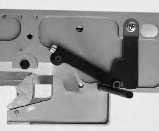
37 10. Cutting knife (eyelet knife) 10.1 Position of the cutting knife 1 2 Caution: Danger of injury! Turn off the main switch. Adjust the cutting knife only with the machine switched off. Standard checking In case of automates for cutting after sewing the cutting knife 2 should cut exactly between the seam rows and in the center of the eyelet (see illustration a). In case of cutting before sewing the cutting knife should cut exactly on the superimposed stitches and around the eyelet (see illustration b). Attention: Danger of breakage! Please take absolute care that the cutting knife corresponds to the subclass and to the sewing equipment. According to the sewing equipment the position of cutting knife 2 and cutting block 1 (not in use on the photo) can be different. Please take care in any case that the correct position of cutting knife and cutting block is adjusted when the sewing equipment is changed on the control panel. The position of the cutting knife is indicated in the table on the next page. Furthermore, the matching clamping plates and fabric clamps must be used for the new sewing equipment. The machine must not be operated before the cutting block, the cutting knife, the clamping plate and the fabric clamps have been adapted to the new sewing equipment. a) b)


38 The cutting knife has to be adjusted in such a way that it cuts in the center of the sewn buttonhole shape. Insert the cutting block. Insert a short needle. Load a piece of paper or cardboard as sewing material. Sew a buttonhole. Check the position of the cut. Correction Loosen the screws 5 at the base plate. Correct the position of the cutting knife 2 laterally. Tighten the screws 5 at the base plate. Loosen screw 4. Shift the cutting knife 2 to the front or to the back. For presetting shift the cutting knife to the setting dimension X (center of buttonhole eyelet to the groove of the throat plate fixture) listed in the table (see chapter 10.2). For fine adjustment shift the cutting knife in such a way that it cuts in the centre of the buttonhole shape. Tighten screw 4. Loosen screw 6. Position guide 7 close to the cutting knife. Tighten screw
39 10.2 Setting dimensions Subclass Sewing equip. Setting dimension E 1101/ E 1121 approx. 59 mm E 1151/ E 1171 approx. 47 mm E 1190/ E 1195 approx. 49,5 mm up to the centre of the stitched eyelet E 1201/ E 1221 E 1202/ E 1222 E 1204/ E 1224 approx. 59 mm E 1401/ L1 E 1421/ L1 E 140/ L1 E 142/ L1 approx. 47 mm E 1401/ L2 E 1421/ L2 E 140/ L2 E 142/ L2 approx. 51 mm E 1401/ L E 1421/ L E 140/ L E 142/ L approx. 59 mm E 1501/ E 1521 E 1502/ E 1522 E 1504/ E 1524 approx. 59 mm E 1551/ E 1571 E 155/ E 157 approx. 47 mm E 1590/ E 1595 approx. 49,5 mm up to the centre of the eyelet 5


40 10. Adjusting the knife parallel to the cutting block Caution: Danger of injury! Turn off the main switch. Adjust the knife only with the machine switched off. Loosen screws 1, 2 and. Put the key 4 (in the accessories) on the hexagonal bolt 5 and twist it. Push the cutting block 6 downward. Check whether the cutting block 6 and the knife 7 are parallel. Tighten the screws 1, 2 and again. 6

 on the hexagonal bolt 5 and twist it. Push the cutting block 6 downward.")
41 10.4 Adjusting the knife parallel to the cutting block with Multiflex machines Caution: Danger of injury! Turn off the main switch. Adjust the knife only with the machine switched off. Correction with the subclasses and Disconnect the machine from the pneumatic supply system. Move the carriage in a way that the screw 1 can be unfastened witha2mmallenkey. Loosen screws 2 and. Put the key 4 (in the accessories) on the hexagonal bolt 5 and twist it. Push the cutting block 6 downward. Check whether the cutting block 6 is in parallel position to the knife 7. Tighten the screws 1, 2 and again. Connect the machine to the pneumatic supply system again. 7


42 10.5 Cutting block adjustment Caution: Danger of injury! Turnthemainswitchoff. Adjust the cutting block only with the machine switched off. The cutting length can be altered by changing the cutting block. The cutting length is determined by the cutting block length. Standard checking The cutting block must be in parallel position to the knife 4. The cutting block stop 5 has to be adjusted so that the knife mark on the cutting block reaches the indicated cutting length. Correction (applies to the subclasses and , too) Loosen the screws 1. Adjust the cutting block 2 laterally to the cutting knife 4. Tighten the screws 1 Loosen screw 2. Adjust the cutting block in longitudinal direction to the cutting knife 4. Tighten screw 2. Loosen screw 6. Position the stop 5 close to the cutting block. Tighten screw 6. 8
43 Adjusting the cutting block position (Multiflex system) Caution: Danger of injury! Turnthemainswitchoff. Adjust the cutting block position only with the machine switched off. The knife 5 has on each side two marks and a number marked. The setting positions for a 10 mm cutting block are situated on one side and on the other side for a 17 mm cutting block. The setting of the 17 mm cutting block will be explained here. Standard checking If the cutting block is located at its right end position (picture on the left), its left edge should stand on the right line 4 of the knife. If the cutting block is located at its left end position (picture on the right), its left edge 7 should stand on the left line 8 of the knife. Correction Disconnect the machine from the pneumatic supply system. Push the cutting block holder 6 downward, until it lays on the knife. Push the cutting block to its right end position. The left edge of the cutting block must stand on the right line 4 of the knife. Loosen the screw 2. Adjust the position of the left cutting block edge by means of the screw 1. Tighten the screw 2 again. 9
44 Push the cutting block to its left end position (picture on the right). The left edge 4 of the cutting block must stand on the left mark 5 of the knife. Loosen the counter nut 2. Adjust the position of the cutting block by means of the screw 1. Tighten the counter nut 2 again. Connect the machine to the pneumatic supply system again. Hint The cutting block holder will then move automatically upward and the cutting block to its right end position, after the compressed air hose is connected. 40
. Insert a piece of cardboard as sewing material. Sew a buttonhole. Measure the cutting length.")
45 2 1 Fine adjustment (right end position) For a 17 mm cutting block, set a buttonhole of 16 mm length without tack and for a 10 mm cutting block, set a buttonhole of 9 mm length without tack on the control panel. Insert a tapping needle (short needle). Insert a piece of cardboard as sewing material. Sew a buttonhole. Measure the cutting length. The cutting length must amount exactly either 16 mm or 9 mm. Correction Loosen screw 2. Adjust the right end position of the cutting block by means of the screw 1. Turn the screw to the right = increase the cutting length Turn the screw to the left = decrease the cutting length Tighten screw 2. 41
. Insert a piece of cardboard as sewing material. Sew a buttonhole. Measure the cutting length.")
46 2 1 Fine adjustment (left end position) For a 17 mm cutting block, set a buttonhole of 20 mm length without tack and for a 10 mm cutting block, set a buttonhole of 14 mm length without tack on the control panel. Insert a tapping needle (short needle). Insert a piece of cardboard as sewing material. Sew a buttonhole. Measure the cutting length. The cutting length must amount exactly either 20 mm or 14 mm. Correction Loosen the counter nut 2. Adjust the left end position of the cutting block by means of the screw 1. Turn the screw to the right = decrease the cutting length Turn the screw to the left = increase the cutting length Tighten the counter nut 2 again. 42


47 10.6 Setting the switch for the Multiflex cutting system Caution: Danger of injury! Turnthemainswitchoff. Set the switch for the cutting system only with the machine switched off. Standard checking When the cutting block is at its upper position, the lower edge 2 of the fork 1 should be on the same level as the lower edge of the switch. There must be a distance of 2 mm between the switch and the fork 1. Correcting the switch height Loosen screw 5. Shift the plate 4 with the switch upward. Tighten screw 5. Correction distance between the switch and the fork Loosen the counter nut 6. Set the switch and the nut 7 in a way that a 2 mm distance is kept. Tighten the counter nut 6. 4
48 10.7 Cutting pressure Standard checking In order to keep the strain of all components as low as possible and to increase the life of the cutting knife, the cutting pressure can be adjusted. Depending on the sewing material and the material thickness, the cutting pressure should be adjusted to be as low as possible. However, it has to be adjusted in such a way that the material is cut safely. The cutting pressure is associated with different cutting lengths in the program. Correction See operating instructions chapter Cutting duration Standard checking It is possible to set the cutting duration, to avoid an unnecessary long cut on the material to be processed thus allowing a clean result. Correction See chapter


49 11. Looper height Before adjusting the loop stroke as well as the needle bar height and particularly after needle breakage it is necessary to check the correct looper height. Use gauge 2 for checking the looper height. Caution: Danger of injury! Turnthemainswitchoff. Set the height of the looper only with the machine switched off. Standard checking When the gauge is put on the looper support, please observe the following: The drill-hole 1 of the gauge must be on top right. The tip of the left looper must be under the edge of the gauge. The tip of the right looper must be under the edge 4 of the gauge. The looper tips must just abut on the gauge Remove the thread trimmer 9, the throat plate 10, the spreader stops 5 and 8 as well as the spreaders 6 and 7 from the looper turrets. Bring the needle bar in position up by turning the handwheel. Put the gauge 2 on the looper turret with the loopers inserted in the looper turrets as far as it will go. In this position the rules mentioned above must be fulfilled. Correction Set the correct looper height by slight alignment of the loopers. 45

50 12. Adjusting the loop stroke Caution: Danger of injury! Turnthemainswitchoff. Adjust the loop stroke only with the machine switched off. Standard checking The loop stroke is the way of the needle bar from its lowest position up to the point where the left or right looper tip is at the level of the middle of the needle. The loop stroke is 2.7 mm. Turn the handwheel in rotation direction until the needle is in the bottom dead centre. Measure the distance between the edge 1 and the top edge of needle bar 2 with a vernier caliper. Scale down the dimension on the vernier caliper by 2.7 mm. Put the vernier caliper with the scaled-down dimension on the edge 1. Slowly continue turning the handwheel in rotation direction until the needle bar hits the vernier caliper. The needle bar is in loop stroke position. Check whether the looper tip is at the level of the middle of the needle (see illustration on the left). Repeat the same procedure with the second looper. 46
 to the needle.")
51 6 4 5 Correction Shift the clamping rings and 4 in such a way that both looper tips have the same distance to the needle. Adjust the left looper 8 and the right looper 7 so that both looper tips in loop stroke position have the same position (X) to the needle. That means both looper tips must be at an equal distance either before or behind the needle. Loosen the screws at the clamping rings and 4. Adjust the looper position as described by shifting the clamping rings. Tighten the screws and 4. It must still be possible to turn the looper turret easily after tightening the screws. If the looper tips are not at the level of the middle of the needle, loosen the screws at the eccentric 5. Turn the eccentric 5 until the looper tips are at the level of the middle of the needle. Tighten the screws at the eccentric 5. Note The washer 6 must still be freely movable after tightening

52 1. Needle bar height Caution: Danger of injury! Turnthemainswitchoff. Adjust the needle bars only with the machine switched off. Standard checking The needle bar has to be adjusted in such a way that approx. ¾ of the needle s eye is to be seen under the left looper tip when the needle bar has moved upward by 2.5 mm from the loop stroke position. Turn the handwheel until the needle is in the bottom dead centre. Measure the distance between the edge 1 and the top edge of needle bar 2 with a vernier caliper. Scale down the dimension on the vernier caliper by the loop stroke dimension +2.5 mm. Example: Loop stroke = 2.7 mm +2.5 mm = Scale the dimension down by 5.2 mm Put the vernier caliper with the scaled-down dimension on the edge 1. Slowly continue turning the handwheel in rotation direction until the needle bar hits the vernier caliper. Correction Loosen the screws at the adjusting rings and 4. Adjust the height of needle bar 5. Tighten the screws at the adjusting rings and 4. Note It must still be possible to turn the needle bar easily after tightening the screws. 48


53 14. Distance between looper and needle Caution: Danger of injury! Turnthemainswitchoff. Adjust the needle protection only with the machine switched off. Standard checking The looper tips 1 and 4 should be in a distance of max. 0.1 mm to the needle. The distance between looper and needle should be equal during the whole rotary motion of the looper turret. Turn the handwheel until the left looper tip is at the level of the middle of the needle. Check the distance between needle and looper tip in the following positions. 1. Looper turret basic position 2. Looper turret manually turned by 90. Looper turret manually turned by 180 If the distance between looper tip and needle is different in the three positions, first align the rotary centres of needle bar and looper turret. Correction Loosen screw 2 at the corresponding looper. Set the distance between looper and needle accordingly. Tighten screw 2. 0,1 mm 49

54 15. Needle protection 1 2 Caution: Danger of injury! Turnthemainswitchoff. Adjust the needle protection only with the machine switched off. Standard checking The needle 1 must slightly abut on the needle protection 2 until the looper tips have reached the needle. The distance between looper and needle must amount to 0.1 mm. The needle protection has been adjusted by the manufacturer. Usually a readjustment is not required. In case other needle sizes are used it may be necessary to readjust the needle protection. Correction Loosen the counter-nut. Turn the Allen screw. 50

.")

.")
55 16. Spreader Caution: Danger of injury! Turnthemainswitchoff. Adjust the spreader only with the machine switched off. Standard checking The distance between the fork spreader 5 and the left looper 4 must correspond to the thickness of the looper thread used (see illustration X opposite). The right spreader 2 should move as closely as possible on the top side of the right looper, but without touching it. The spreaders being under spring pressure are held in their end position by the stops 1 and 6. The fork of the left spreader 5 should be exactly above the thread hole of the left looper 4 (see opposite illustration) and the point of the right spreader 2 centrally above the tip of the right looper (see illustration at the bottom of the page). Correction For adjusting the distance between spreader and looper slightly align the spreaders. For setting the final positions of the spreaders loosen the screws 7 or 8 at the looper to be adjusted. Turn spreader stop 1 or 6 slightly. Tighten screw 7 or 8. 51

, when the needle is in the bottom dead")

56 17. Spreader plate X1 X2 2 1 Caution: Danger of injury! Turnthemainswitchoff. Adjust the spreader plate only with the machine switched off. Standard checking The opening and closing of the spreaders is effected by the alternate motion of the spreader plate 2. When the needle bar is in the bottom dead centre for the right stitch, the distance between spreader plate 2 and spreader leg 1 must be exactly the same as that between spreader plate 2 and spreader leg (dimension X1 = dimension X2), when the needle is in the bottom dead centre for the left stitch Correction Loosen the screws at the clamping rings 4 and 6. Move the clamping rings in such a way that the distance between spreader plate and spreader legs is equal. Tighten the screws at the clamping rings 4 and 6. Note The washer 5 must still be freely movable after tightening. 52


57 18. Throat plate 2 1 Caution: Danger of injury! Turnthemainswitchoff. Adjust the throat plate only with the machine switched off. Standard checking The needle should penetrate the needle hole of the throat plate on one side at the edge 1. The throat plate has to be positioned as high as possible. Thus it is avoided that the material is pressed down too much at the moment of the needle penetration. During the sewing process there must be a small distance to the throat plate at the following points: Under the sewing material or the closed upper fabric clamps respectively. It must be possible for the sewing material to move over the throat plate unhindered. Under the lower fabric clamps. Above the needle thread knife. The needle thread knife must move as closely as possible under the throat plate, but without touching it. Correction Adjust the height of the throat plate at the stop screw 2 in the throat plate guide. By means of the stop screw the adjustment is maintained when inserting the throat plate anew. 5


58 19. Adjusting the needle thread knife Caution: Danger of injury! Turnthemainswitchoff. Adjust the needle thread knife only with the machine switched off. 5 Standard checking The cutting motion of the needle thread knife 2 is effected after sewing. The exact cutting moment is set in the program. When in final position the knife holder must not touch the spreader stop 1. The needle thread knife should cut through the needle thread loop taken up from the right looper at the looper front 5 only. If the needle thread loop is cut through on both sides, this results in a too short thread end and thus in skip stitches at the seam beginning. In the right final position the needle thread knife must neither be in the thread zone nor touch the spreader stop. There must be a distance of approx. 0.2 mm between needle and knife. In cut-off position the knife must move approx. 1 mm beyond the edge 4. Move the knife manually and check whether all rules mentioned above are kept. 0,2 mm 54

59 Correction of the knife motion Loosen the counter-nuts 5 and 8. Adjustthestopscrews6and7accordingtotherule. Tighten the counter-nuts 5 and 8. Adjusting the height of the knife Loosen screw 10. Adjust the height of the knife holder 9 correspondingly. Swing the knife holder 9 manually to check the free movement. Tighten screw 10 again. Adjusting the distance to the needle Loosen screw 11. Shift knife 12. Tighten screw

60 20. Adjusting the fabric clamps Caution: Danger of injury! Turnthemainswitchoff. Adjust the fabric clamps only with the machine switched off. Standard checking Between the needle 2 and the upper fabric clamp 1 there should be a distance of 1 mm over the whole length and in the eyelet. Insert the clamping plates. Insert a new needle. Switch the machine on. Press key F. Enter code Press key OK. The control switches to the technician level. Select menu Test functions. Press key OK. Select menu Multitest. Press key OK. Select menu Output test. Press key OK. Select function Y0 (closing the fabric clamp). Press key OK. The fabric clamps close. Select function Y04. Press key OK. The clamping plates spread. Check the distance between upper fabric clamp 1 and needle 2. 56
61 Correction Loosen screws (underside). Align clamp bow 7 with fabric clamp 5 laterally to the needle. Tighten screws. Loosen screws 4. Align clamp arm 6 with fabric clamp 5 in the eyelet as to the needle. Tighten screw 5. 57


62 21. Thread thread take-up spring Caution: Danger of injury! Turnthemainswitchoff. Adjust the thread take-up spring only with the machine switched off. Standard checking The thread take-up spring 1 must hold the looper thread tensioned until the needle with the needle thread has accurately penetrated the triangle formed by the spreader. Insert and clamp the material. Turn the machine manually and check whether the thread take-up spring tightens the looper thread firmly and long enough. Correction of the spring travel Loosen screw 4. Adjust the stop disc. Disc to the right = longer spring travel Disc to the left = shorter spring travel Tighten screw 4. Correction of the spring tension Loosen screw 5. Adjust the tension bolt 2. Bolt to the right = higher tension Bolt to the left = lower tension Tighten screw 5. 58
63 22. Short trimmer for lower thread ( , ) 22.1 Function sequence 1 A B After the seam end the cutting motion of the needle thread knife is effected. At the same time the short-trimmer is brought to the initial position (fig. B) for trimming the lower thread (looper thread). The lower thread glides in front of the edge of knife 1. Afterwards the short-trimmer is switched back (fig. A). By switching back the lower thread is clamped and cut. In order to guarantee that the lower thread is safely clamped at the seam beginning the spring must press the knife against the knife plate. The clamping pressure has to be set in such a way that the lower thread is safely held. If the clamping pressure is too high, the stitches at the seam beginning are too tight. 59

64 1 5 0,1 mm 1 2 5,0 mm 0,1 mm A 4 B
65 22.2 Initial position Caution: Danger of injury! Exercise utmost caution when making adjustments with the machine running. Standard checking In the two positions (fig. A and fig. B) of the short-trimmer the knife 1 must not be visible in the needle hole 2 and the distance between throat plate and block 4 must amount to approx. 5 mm. Block 4 and knife holder 5 must not touch the throat plate in any position of knife 1. Switch the machine on. The short-trimmer is in the initial position (fig. A). Check the knife position in the throat plate. Knife 1 must not be visible in the needle hole 2. Check the distance between knife holder 5 and throat plate (fig. A). Check the dimension 5 mm between block 4 and throat plate. Press key F. Enter code Press key OK. The control switches to the technician mode. Select the menu item Test functions with key. Press key OK. The control switches to the menu item. Select menu item Multitest. Press key OK. Select menu item Output test". Press key OK. Select output Y00. Press key OK. The short-trimmer and the needle thread trimmer are engaged simultaneously. Check the knife position in the throat plate. Knife 1 must not be visible in the needle hole 2. Check the distance between block 4 and throat plate (fig. B) Correction Dimension 5 mm between block and throat plate (fig. A) Loosen screw 6. Remove throat plate and suction device 7. Set the dimension 5 mm by turning the block 4. Attention! The thread has to be secured against loosening using a securing compound. 61
66 1 5 0,1 mm 1 2 5,0 mm 0,1 mm A 4 B Correction basic position (fig. A) Loosen counter-nut 8. Turn the stop screw 9. Tighten counter-nut 8. Correction switching position (fig. B) Loosen counter-nut 10. Turn the piston rod 11. Tighten counter-nut 10 again. 62


67 22. Adjusting the cutting pressure / clamping pressure 1 2 A B Standard checking The cutting pressure has to be set so that the looper thread is precisely cut and clamped. Loosen screw 7. Remove throat plate and aspiration 6. Open the slide 2 of the throat plate manually so that the slide is in the position according to fig. B. Guide the thread 1 through the center of the needle hole. Move the slide 2 manually to the position according to fig. A. A slight pressure has to be felt when pushing. The thread has to be cut totally. The thread must be clamped after cutting. 6 7 Attention! A too high cutting pressure results in increased knife wear and intensely contracted stitches at the seam beginning. Loosen screw 8. Shift the spring sheet 9. Tighten screw 8. Reinsert throat plate as well as aspiration 6 and tighten with screw
68 22.4 Knife change The parts of the knife kit can be exchanged if necessary. Part No. Spring sheet Knife plate Knife Loosen screws 1, 2 and 4 of the knife plate. Remove the knife plate. Loosen screw 5. Remove knife 6. Insert new knife 6 and tighten with screw 5. There must be a bush on the screw 5. The knife has to be flexibly connected to the slide. Put on the new knife plate and tighten with the screws 1 and 4. Set the cutting pressure by the screw 2 (see chapter 22.2). 64


69 2. Long trimmer for looper thread and gimp ( and ) 2.1 Cutting pressure and cutting motion Caution: Danger of injury! Adjust thread clamp and thread deflector only with the machine switched off. Standard checking The deflector 2 is mounted above the stationary knife. It avoids that the gimp and looper thread ends get between knife and the back of the thread catcher 1. They are guided into the thread catcher or next to it instead. If this is not the case, the knife can be pushed aside and does not cut. The cutting pressure must only be as high as it is necessary for a safe thread trimming. The thread catcher must pass the thread clamps 7 as close as possible, but must not touch them. Correction Thread deflector Loosen the screws 4. Align the thread deflector 2 laterally in such a way that the function described above is achieved. Tighten the screws 4 again. 7 6 Cutting pressure Loosen the screws 5. Shift the stationary knife so that the looper thread and the gimp thread are cut safely. Tighten the screws 5. Distance between the thread clamps and the thread catcher Loosen the screws 6. Shift the thread clamps 7. Tighten the screws 6. 65


70 2.2 Adjusting the knife overlap Caution: Danger of injury! Adjust the trimmer for threads cut long only with the machine switched off. Standard checking The blades 1 and must move one on top of the other by 1 mm. It must be possible to insert the clamping plate without jamming. The roller 2 must reach in the groove of the linkage 5. Remove the right clamping plate. Reinsert the right clamping plate. It must be possible to insert the clamping plate without jamming. Correction Adjusting the linkage Loosen screw 4. Shift the linkage 5 on the piston rod. The dimension X should amount to 9 mm. Tighten screw 4. 66
. Tighten screw 6. Insert clamping plates. Switch the machine on.")
71 7 6 Adjusting the overlap Loosen the clamping screw 6. Turn the lever 7. Set the dimension 61 mm (see illustration on the left). Tighten screw 6. Insert clamping plates. Switch the machine on. Check the size of the overlap. Switch the machine off. 67


72
73 2. Position of the looper thread and gimp clamp Caution: Danger of injury! Adjust the position of the looper thread and gimp clamp only with the machine switched off. Standard checking The long-trimmer clamps both the looper thread and the gimp under a clamping sheet. looper thread and gimp have to be held as tight that a safe and tight seam beginning is guaranteed. Before the cutting operation at the stationary knife starts, looper thread and gimp thread must be pulled between the lower clamping spring 2 and the clamping piece 1. In order to ensure that the gimp and the looper thread are safely pulled between clamping spring 2 and clamping piece 1 before cutting, the clamping spring is opened by the release sheet above the pin 4. The opening width depends on the thickness of the bobbin and gimp thread used. The clamp must be opened at least as wide as to ensure that the threads are safely pulled in front of pin 4 and that they are not pulled out of the thread clamp after thread trimming. When the blade of the thread catcher 5 is approx. 1 mm in front of knife 6, the release sheet must close the thread clamp again. The pin 4 must then be free again. The tip 7 of the thread catcher must push itself under the looper thread and the gimp. Correction Opening width Align the height of the release sheet so that the clamping spring for looper thread and gimp is opened. Time Loosen the screws 8 slightly. Turn the thread clamp 9 so that it is closed when the blade of the thread catcher is 1 mm in front of the knife. Tighten the screws 8. Clamping force Adjust the pressure of the clamping spring 2 by aligning so that the looper thread is slightly clamped after trimming and does not jump back. 69

74 2.4 Thread deflector 1 Standard checking The thread deflector 1 avoids that the thread at the seam beginning is cut. Thus, there is no cutting waste any longer. The thread deflector cannot be adjusted. If there is cutting waste, insert a new thread deflector. 70
75 Notes: 71


76
77 24. Short trimmer for looper thread and gimp ( ) Caution: Danger of injury! Adjust the short-trimmer only with the machine switched off. Standard checking The cutting edges of the two scissors 2 and must have moved approx. 1 mm one on top of the other before reaching their stationary point. The cutting pressure has to be adjusted so that the looper thread and the gimp are safely cut. The knife must not move too heavy or jam. It must be possible to insert the clamping plates without jamming. The roller 5 must reach into the gap of the linkage 6. Remove both clamping plates. Correction Adjusting the gap Loosen screw 7. Shift the linkage 6 on the piston rod until it abuts on the cylinder together with the plastic bush. Tighten screw 7. Adjusting the overlap Open knives 2 and totally. Loosen screw 8. Put the locking pin 10 in the drill-hole 11. Turn the lever 9 against the locking pin. Tighten screw 8. Cutting pressure Loosen nut 4. Set the cutting pressure by the screw 1. The cutting pressure has to be adjusted in such a way that a good trimming result is achieved with the lowest possible cutting pressure. Tighten nut 4. Make a manual trimming test with the looper thread or the gimp and check the smooth running of the knife movement. 7
. Loosen the screws 1 and remove the cover 2. Screw the spacer 4 on the knife with the screws 5. Screw on the cover 6 with the screws.")
78 24.1 Optional equipment for subclass Remark: You can lengthen the end thread on the underside of the buttonhole by using additional sewing equipment (see accessories). Loosen the screws 1 and remove the cover 2. Screw the spacer 4 on the knife with the screws 5. Screw on the cover 6 with the screws. 74


79 25. Gimp pulling device for subclass Caution: Danger of injury! Adjust the gimp pulling device only in position Safe stop or with the machine switched off respectively. Standard checking The drop weight 2 pulls the gimp back to the correct initial length. The course of the drop weight has to be limited by the stop screw in such a way that the gimp is as short as possible at the sewing start, but sewn in safely. This is the case when the gimp end juts out of the gimp hole of the throat plate by approx. 4 mm. Correction Screw in screw = longer gimp end Screw out screw = shorter gimp 75

80 26. Thread catcher 26.1 General notes 1 Immediately after thread trimming the needle thread catcher 1 seizes the needle thread, holds it clamped and places it in the right lip when sewing the next buttonhole. This offers the following advantages: Safe seam beginning, even in light, loose fabrics. Tight stitches at the seam beginning. The needle thread is sewn into the buttonhole lip and does not need trimming. Function sequence After the sewing cycle is started, the needle thread catcher lowers on the workpiece with the thread clamped. The sewing operation starts with the right buttonhole lip. The needle thread end positioned by the thread catcher is stitched over and sewn in. After a point defined in the control the thread catcher lifts and moves back to the position up. Just before the seam end the clamp of the thread catcher is opened, and the thread catcher moves down. After the end of the left buttonhole lip the needle stops in the upper position. The needle thread is cut. The thread catcher moves to the front. The clamp is closed. The thread is caught. The thread catcher moves backwards. The thread catcher moves upwards. 76


81 26.2 Adjustment Caution: Danger of injury! Adjust the thread catcher only with the machine switched off. Standard checking The thread catcher must safely catch the needle thread after sewing a buttonhole. The thread catcher must place the needle thread in the right buttonhole lip. The thread catcher must not collide with the clamping plates. When the thread catcher is in basic position, the following conditions must be fulfilled: The thread catcher 1 must not hit the screw 2. The distance between the front edge of the thread catcher 4 and the needle should amount to approx. 7-8 mm. Laterally the needle and the left edge of the clamp 10 of the thread catcher must stand in a line. 10 According to the thickness of the material used the lower position has to be adjusted differently. When the thread catcher is lowered, there must still be a distance of approx. mm between the lower edge and the fabric. When the thread catcher is lowered and moved to the front, the loop 10 of the thread clamp must approximately be at the level of the middle of the needle. Sew a buttonhole. The thread catcher must not collide with the clamping plates during the sewing operation. The thread has to be safely caught after the sewing operation. Check whether the needle thread has been sewn in the centre of the right buttonhole lip. 77

82 Correction Height of the thread catcher Loosen screw 2. Adjust the height of block. Tighten screw 2. Distance between thread catcher and needle Loosen counter-nut 1. Set the distance to the needle with the stop screw 7. The distance between thread catcher and needle must amount to approx. 7-8 mm. In some cases the distance to the needle can slightly differ from this value. Tighten counter-nut 1. Lower position of the thread catcher Set the lower position of the thread catcher with the knurled screw 4. The distance between thread catcher and fabric must amount to approx. mm. Press the thread catcher down manually and check the position of the thread catcher. Lateral position of the thread catcher Loosen screws 6. Adjust the lateral distance of the thread catcher 5. Tighten screws 6. 78

.")
83 26. Subsequent fitting of the thread catcher Caution: Danger of injury! Mount the thread catcher only with the machine switched off. If a thread catcher is mounted subsequently, the pneumatic base plate 1 has to be supplemented by three valves. Screw off the covers of the valve locations 9, 10 and 11 and screw on the solenoid valves delivered with the mounting kit Mount the thread catcher 2. Lay compressed air lines from the solenoid valves to the thread catcher. Valve 9 = thread catcher down (). Valve 10 = open the thread catcher (4). Valve 11 = swivel the thread catcher to the front (5). 79


84 27. Maintenance Caution: Danger of injury! Turnthemainswitchoff. Maintenance work of the automatic buttonholer must only be carried out with the machine switched off. The daily or weekly maintenance work (cleaning and oiling) to be carried out by the operators of the automatic buttonholer is described in Part 1: Operating Instructions. This is only listed in the following table to complete the picture. Maintenance work to be carried out Operating hours Automatic buttonholer Remove the sewing dust from the area under the throat plate Check the oil level Check and clean the toothed belt Oil the cutting stamp 1 Oil the clamp arms at the felt 2 Oil felt 6 at the cam X X X X X X Pneumatic system Check the water level in the pressure regulator Clean the filter insert in the maintenance unit Make leak test of the system X X X 80

85 28. Annex 28.1 Adjusting operations without head cover 2 1 When the head cover is taken off, the machine is secured against unintentional starting. If you want to operate the machine without head cover for adjusting purposes, the plug 2 can be put on the connecting cable. The plug is in the switch casing 1. Caution: Danger of injury! Remove the head cover for adjustment work only. Exercise utmost caution when making adjustments with the machine running. 81


86 28.2 Fuses in the control box 1 2 The fuses 1 and 2 for the control are on the back of the control box. Only insert the fuses indicated in the circuit diagram. 28. Exchange of the control See: Part 2: Installation Instructions. Assembly of the main switch Assembly of the control Potential equalization Installing the sewing software 28.4 Adjusting the contrast of the control panel Put a small screwdriver in the hole 2 through the opening 1. Twist the screw in the hole 2. The display will then be brighter or darker


87 29. Service menu (technician level) In the service menu of the 580 various basic adjustments and test programs can be executed Activating the service menu Press key F at the control panel. A code query appears. Enter the code 2548 with the cursor keys. Press key OK. The service menu appears. With the cursor keys the individual menus can be selected. With the key OK the selected menu is activated Quitting the service menu Press key ESC. The control switches back to the main menu. 8


88 29. Menu structure cont. next page 84


89 85
90 29..1 Menu structure with numbers Machine config (1) Load pos. (1.1) Zig-zag (1.2) Thread mon. (1.) E-group (1.4) Threading mode (1.6) Standard (1.6.1) Parallel (1.6.2) Operation mode (1.7) Standard (1.7.1) Sample (1.7.2) Tandem (1.7.) Indexer (1.7.4) Tension data (1.8) Data 1 (1.8.1) Data 2 (1.8.2) Data (1.8.) Data 4 (1.8.4) Data 5 (1.8.5) Data 6 (1.8.6) Multiflex (1.9) Mode (1.9.1) X-Corr. L (1.9.2) X-Corr. R (1.9.) Y-Corr. (1.9.4) Block length (1.9.5) Knife L (1.9.6) Knife R (1.9.7) Operat. Config (2) Language (2.1) German (2.2.1) English (2.1.2) Numbers (2.1.) Manual keys (2.2) Sew. Lamp (2.) Key tones (2.4) 86
91 Test functions () Multitest (.1) Output test (.1.1) Input test (.1.2) Auto input test (.1.) Motor test (.1.4) Step. Motor test (.1.5) Flash test (.1.6) RAM test (.1.7) Sewing proc. (.2) Step by Step (.2.1) Start ref. (.2.2) Events (.4) All events (.4.1) Latest events (.4.2) 87
 Standard: 68 The value entered corresponds to the distance from the cutting point. The value 0 corresponds to the cutting-open position.")
92 29.4 Menu items configuration automatic buttonholer Loading position (Load.pos.) Via this menu item the desired loading position can be set. Input: 0 68 (mm) Standard: 68 The value entered corresponds to the distance from the cutting point. The value 0 corresponds to the cutting-open position. The standard value is identical with the seam beginning position Menu item throw width (Zig Zag) In this menu the throw width can be checked and with eyelet machines itcanalsobeset. Caution: Danger of breakage! The throw width must match the mechanical position of the throw eccentric. See chapter 2. Input: 1 = Narrow 2=Wide 88

 The duration of the incision can be set individually so that the material to be processed is cut open accurately and")
93 29.4. Menu item thread monitor (Thread mon.) In this menu the needle thread monitor is set. The set value means: 0 = Thread monitor switched off 1 14 = Number of stitches after which the sewing process is aborted because of thread breakage Input: 0 14 Standard: Menu item duty cycle of cutting block (Cut. time) The duration of the incision can be set individually so that the material to be processed is cut open accurately and no longer than required. Input: Standard:

94 Menu item sewing equipment Various sewing equipment can be used with the automatic buttonholer 580. The selected sewing equipment is entered via this menu item. Input: narrow wide E 1101 E 1121 E 1151 E 1171 E 1190 E E 1201 E 1221 E 1224 E 1202 E 1222 E E 1401/ L1 E 1421/ L1 E 1401/ L2 E 1421/ L2 E 1401/ L E 1421/ L E 140/ L1 E 140/ L2 E 140/ L E 142/ L1 E 142/ L2 E 142/ L E 1501 E 1521 E 1502 E 1522 E 1504 E 1524 E 1551 E 1571 E 155 E157 E 1590 E E 101 E E 201 E


95 Menu item threading mode (Threading mode) In this menu the setting of the machine can be selected. The value set means : Standard = Normal inserting Parallel = Sidewise inserting Entry: Standard / Parallel Menu item operation mode (Operation mode) In this menu the operation mode of the machine can be set. The value set means : Standard sewing normally Sample with high-quality buttonholes, the machine halts before cutting the buttonhole. Thus, allowing the seamstress to verify the buttonhole. Tandem connecting a second machine for operation in tandem. Indexer the machine is installed on indexer. Entry: Standard/ Sample/ Tandem/ Indexer 91
96 Menu item tension data (Tension data) In this menu the characteristic values for the magnets of the needle thread tension can be set. Attention! Only change the characteristic values of the magnets, when mounting new magnet. When ordering new magnet, the corresponding values are enclosed with. Changing the characteristic values Press the F key. Select the menu Machine config.. Select the menu Tension data. Enter the code. Enter value from 1 to 6. 92
 Multi Multiflex cutting system Mode Mono X-correction left buttonhole X-correction right buttonhole Y-correction for both buttonholes Mode")
97 Menu item Multiflex (Multiflex) In this menu the built-in cutting system can be set. The value set means : Mono normal cutting system (2x cut) Multi Multiflex cutting system Mode Mono X-correction left buttonhole X-correction right buttonhole Y-correction for both buttonholes Mode Multi X-correction left buttonhole X-correction right buttonhole Y-correction for both buttonholes Block length Knife number for left knife Knife number for right knife Buttonhole knife and -blocks Part-No. Knife- Form Number with eye 2,8 x 4, x 6 mm with eye 2,1 x,2 x 6 mm Mid cut without eye 8 mm only eye 2,8 x 4, mm only eye 2,1 x,2 mm without eye 6 mm Mid cut with eye 2,8 x 4, x 8 mm Mid cut with eye 2,1 x,2 x 8 mm Eyelet ø 1,0 mm Eyelet ø 1,5 mm Eyelet ø 2,0 mm Eyelet ø,0 mm Eyelet ø 4,0 mm Cutting block 17 mm Cutting block 10 mm Cutting block 26 mm 9
 Key 1: The clamping plates are opened or closed. Key 2: The sewing process only starts with the clamping plates closed.")
98 29.5 Menu item operating configuration Menu item language In this menu the desired language is selected. Languages:German English Numbers Menu item push-buttons In this menu the function of the push-button is converted. 1 st adjustment = 1 (Standard) Key 1: The clamping plates are opened or closed. Key 2: The sewing process only starts with the clamping plates closed. 2 nd adjustment = 2 Key 1: The clamping plates are opened or closed. Key 2: The sewing operation starts. The clamping plates are closed automatically. 94
99 29.5. Menu item brightness of the sewing lamp In this menu the brightness of the incorporated sewing lamp is set. The value set means: 0 = Sewing lamp off 100 = Sewing lamp very bright Standard: Menu item key tones In this menu the key tones are switched on and off. The value set means: 0 off 1-50 Beep in milli-seconds with every touch of the button. 95
100 29.6 Menu items test functions multitest The test functions allow the quick test of input and output elements. Additional measuring instruments are not required. 96
101 Menu item output test Attention: Danger of breakage! The switching of output elements can lead to collisions with other machine elements as well as to damages to the automatic buttonholer. Before switching on an output element make sure that this cannot collide with other components. Caution: Danger of injury! Exercise utmost caution when making the output test with the machine running. In this menu the individual output elements can be engaged. Select the desired output element with the keys or. The current status is shown in the display: 0 = Output inactive 1 = Output active Press key OK. The output is converted. Output Designation Y01 Needle thread trimmer, with and additionally looper thread cutter Y02 Looper thread tension Y0 Fabric clamp Y04 Spreading Y05 Needle thread puller Y06 Cutter Y07 Cutter Y08 Looper thread pulling, only / Y09 Needle thread catcher (material) Y10 Open the needle thread catcher Y11 Needle thread catcher (needle) Y12 Looper thread cutter, only / / Y1 Knife Multiflex, only / Y14 Cutting block Multiflex, only / Y15 Cutter Quit the output test with key ESC. 97
102 Menu item manual input test Caution: Danger of injury! Exercise utmost caution when making the input test with the machine running. In this menu individual input elements can be tested. Select the desired input element with the keys or. The current status is shown in the display: 0 = Input inactive 1 = Input active Input Designation S0 Multiflex S04 Light barrier mode S05 Light barrier mode S09 Push button 1 S10 Push button 2 S11 Foot pedal 1 S12 Foot pedal 2 S1 Foot pedal RefN Sewing motor RefX X-axis RefY Y-axis RefZ Z-axis Quit the input test by pressing the ESC key. 98

103 29.6. Menu item automatic input test Caution: Danger of injury! Exercise utmost caution when making the input test with the machine running. With this menu item the function of all input elements is tested. If the status of an input is altered, this input is automatically indicated in the display. Quit the input test by pressing the ESC key. 99
104 Menu item sewing motor test With this menu item the sewing motor can be checked. During the test the speed can be increased in steps of 100. Attention: Danger of breakage! Before starting the sewing motor test remove the clamping plates in any case. Caution: Danger of injury! Exercise utmost caution when making the sewing motor test. Increase the speed with key. Reduce the speed with key. Quit the motor test with key ESC. 100
105 Menu item step motor test With this menu item the step motors can be checked. The step motors are checked with the related reference switches. Attention: Danger of breakage! Before starting the step motor test remove the clamping plates in any case. Caution: Danger of injury! Exercise utmost caution when making the step motor test. Select the corresponding step motor X...Z with the keys or. With the keys or the step motor runs each 20 steps forwards or backwards. X = X-direction (transversal motion of the fabric support plate) Y = Y-direction (longitudinal motion of the fabric support plate) Z = Z-direction (rotary motion of the sewing works) Quit the step motor test by pressing the ESC key. 101
106 Menu item flash test In this menu item the flash memory is checked. Display: On the left: Calculated checksum On the right: OK or Error Quit the flash memory test with key ESC Menu item RAM-test In this menu item the working memory (RAM) is checked. OK = Working memory works faultlessly Error = Error in the working memory Quit the RAM memory test with key ESC. 102
107 29.7 Menu item test functions / Test program sewing sequence Menu item stop In this menu item the sewing sequence is stopped at various steps. This facilitates the testing and adjusting of the automate. The following is the meaning values set: Caution Risk of injury! The testing program serves only for the checking of cycles and functions. Maintenance and setting work should not be conducted when running the testing program. 0= normal sewing cycle, the testing program is turned off. 1= the sewing cycle is stopped after switching the valves of the thread catcher on. 2= the sewing cycle is stopped after switching the valve of the respective thread trimming system on. = the sewing cycle is stopped after switching each valve on Menu item reference start In this menu item it is possible to start a reference run. This testing program is particularly helpful for the setting of the sewing machine. Caution: Danger of injury! Exercise utmost caution when making the output test with the machine running. 10

108 29.7. Menu item continuous operation (St.cont.operat.) In this menu item the continuous operation mode can be switched on/off. Starting the continuous operation can be done via the query yes/no. Caution Risk of injury! Exercise utmost caution when running the continuous operation. 104
 In this menu item the latest events are displayed. Quit the menu item with key ESC.")
109 29.8 Menu item events Menu item all events (example) In this menu item all events occurred are displayed. Quit the menu item with key ESC. Further displays with key Menu item latest events (example) In this menu item the latest events are displayed. Quit the menu item with key ESC. Further displays with key. 105
581 Service Instructions
 581 Service Instructions IMPORTANT READ CAREFULLY BEFORE USE KEEP FOR FUTURE REFERENCE All rights reserved. Property of Dürkopp Adler AG and protected by copyright. Any reuse of these contents, including
Double-chainstitch buttonhole automat. Single-chainstitch automat for stitched eyelets
 Manual, complete 580 Double-chainstitch buttonhole automat Single-chainstitch automat for stitched eyelets Operating Instructions Installation Instructions Service Instructions 2 3 Postfach 7 03 5, D-33703
PFAFF. rom the library of: Superior Sewing Machine & Supply LLC. Service Manual Justieranl. engi. 7.92
 PFAFF 5642 Service Manual 296-12-13925 Justieranl. engi. 7.92 Notes on safety The machine must only be commissioned in full knowledge of the instruction book and operated by persons with appropriate training.
CNC Knopfannähautomat CNC Automat for Button Sewing
 50 CNC Knopfannähautomat CNC Automat for Button Sewing Bedienanleitung / Operating Instructions Aufstellanleitung / Installation Instructions Serviceanleitung / Service Instructions 1 2 Postfach 17 0 51,
M PREMIUM. Additional Instructions. Neat seam beginning (NSB)
") 867 867-M PREMIUM Additional Instructions Neat seam beginning (NSB) IMPORTANT READ CAREFULLY BEFORE USE KEEP FOR FUTURE REFERENCE All rights reserved. Property of Dürkopp Adler AG and protected by copyright.
867 867-M PREMIUM Additional Instructions Neat seam beginning (NSB) IMPORTANT READ CAREFULLY BEFORE USE KEEP FOR FUTURE REFERENCE All rights reserved. Property of Dürkopp Adler AG and protected by copyright.
SERVICE MANUAL MODEL: 13512, 14412, 15312
 SERVICE MANUAL MODEL: 13512, 14412, 15312 CONTENTS TROUBLESHOOTING... 1-3 SERVICE ACCESS (1) FACE COVER, BELT COVER... 4 SERVICE ACCESS (2) BASE PLATE... 5 SERVICE ACCESS (3) FRONT COVER... 6 SERVICE ACCESS
SERVICE MANUAL AND PARTSLIST
 SERVICE MANUAL AND PARTSLIST Next 20 CONTENTS WHAT TO DO WHEN... 1~3 SERVICE ACCESS FACE COVER... 4 TOP COVER... 4 BASE COVER... 5 REAR COVER... 6 FRONT COVER... 7 MECHANICAL ADJUSTMENT NEEDLE THREAD TENSION...
Symbols used. Move the part in the direction of the arrow. Set the clearance as indicated. Move the part to its highest or lowest position.
 4.1999. This service manual was compiled for use when repairing the XL5300, 5200, 5100, 5030, 5020, 5010,PX300,200,100 Zigzag Stitch Sewing Machines. Use this manual, together with the Parts Catalog, when
CONTENTS PRECAUTIONS BEFORE STARTING OPERATION PREPARATION FOR OPERATION CAUTIONS ON USE OPERATION
 CONTENTS PRECAUTIONS BEFORE STARTING OPERATION ------------------------------------- 1 PREPARATION FOR OPERATION 1. Adjustment of needle bar stop position ---------------------------------------------------------
FBX-PA-2AC. Third edition : April No
 FBX-PA-2AC Third edition : April 2006 No. 060058 INTRODUCTION Thank you very much for purchasing Kansai Special FBX series. Read and study this Instruction Manual carefully before you start any of the
Basic steps to time the Gammill quilting machine s rotary sewing hook
 Basic steps to time the Gammill quilting machine s rotary sewing hook 1.) Turn the machine off and unplug it. 2.) With the needle bar in the raised position, remove the bobbin and bobbin case. 3.) Remove
SERVICING MANUAL 419S/423S
 SERVICING MANUAL 415 419S/423S TROUBLESHOOTING PROBLEM CAUSE REMEDY REFERENCE 1. SKIPPING 1. NEEDLE IS NOT INSERTED INSERT THE NEEDLE PROPERLY. STITCHES PROPERLY. 2. NEEDLE IS BENT OR WORN. CHANGE THE
SERVICE MANUAL FOR HOMELOCK M1034D 2034D 1134DW 1134D
 SERVICE MANUAL FOR HOMELOCK M1034D 2034D 1134DW 1134D 11.2000 2.2012 I HOW TO USE THIS MANUAL... 1 II HOW TO ADJUST... 2 1. Height of needle bar... 2 2. Position of the lowerlooper... 3 3. Timing of the
ADJUSTMENT MANUAL. This adjustment manual applies to machines from the following serial numbers onwards: #
 45 46 ADJUSTMENT MANUAL This adjustment manual applies to machines from the following serial numbers onwards: # 6 500 4 96--9 00/00 Justieranleitung engl. 0. The reprinting, copying or translation of PFAFF
First published : May 1997 Fourth edition : January No
 First published : May 1997 Fourth edition : January 2006 No. 050153 INTRODUCTION Thank you for your purchasing Kansai Special's FX Series. Read and study this instruction manual carefully before beginning
S-85SCH
 4411-4423-4432-4443-4452 5511-5523-5532-5554 44S-85SCH Service Manual 104 73 14-26 2014-02-24 CONTENTS 1. Names of principal parts...2 2. Removing methods of external parts 2-1 Sewing table...3 2-2 Face
Adjustment Manual. This Adjustment Manual is valid for machines from the following serial numbers onwards: #
 4 Adjustment Manual This Adjustment Manual is valid for machines from the following serial numbers onwards: # 6 00 000 96--8 64/00 Justieranleitung engl. 06.05 The reprinting, copying or translation of
887 Service Instructions
 887 Service Instructions All rights reserved. Property of Dürkopp Adler AG and copyrighted. Reproduction or publication of the content in any manner, even in extracts, without prior written permission
SERVICE MANUAL PARTS LIST MODEL: NH40
 SERVICE MANUAL & PARTS LIST MODEL: NH40 CONTENTS What to do when... 1-3 SERVICE ACCESS Face Cover... 4 Bed Cover... 5 Free-arm Cover... 6 Front Cover... 7 Rear Cover... 8 MECHANICAL ADJUSTMENT Presser
OPERATING INSTRUCTIONS 3421UX VETERANS BLVD, CARLSTADT, NJ 07072
 OPERATING INSTRUCTIONS 3421UX5-1 400 VETERANS BLVD, CARLSTADT, NJ 07072 CONTENTS DESCRIPTION... 3 OPERATOR INFORMATION... 5-8 INSTALLATION...... 4 ADJUSTMENT... 8-17 LUBRICATION... 5 INDEX Description
Brother Industries, Ltd. Nagoya, Japan
 4. 2001. This service manual has been compiled for explaining repair procedures of the MODEL XL-6562, XL6452, XR- 46. This was produced based on up-to-date product specifications at the time of issue,
Part 3: Service Instructions Cl. 558
 Contents Page: Preface and General Safety Notes Part : Service Instructions Cl. 8. General.................................................. Handwheel................................................ Turn-off
WX8800 WX8700 LX5801 WX8842 WX MC30
 WX8800 WX8700 LX5801 WX8842 WX8842-1 MC30 First published : August 1991 Third edition : August 2004 No. 040037 INTRODUCTION Thank you for your purchasing Kansai Special's WX Series. Read and study this
FBX1104P FBX1104 FBX1106P FBX1106
 FBX1104P FBX1104 FBX1106P FBX1106 Second edition : September 2004 No. 040037 INTRODUCTION Thank you for your purchasing Kansai Special's FBX Series. Read and study this instruction manual carefully before
INSTRUCTION BX1425P,PSM,PTV BX1433P,PSM,PTV BX1025P,PSM BX1033P,PSM. No First published : November 1997
 INSTRUCTION Industrial Sewing Machines BX1425P,PSM,PTV BX1433P,PSM,PTV BX1025P,PSM BX1033P,PSM First published : November 1997 No. 970112 INTRODUCTION Thank you for your purchasing Kansai Special's BX
INSTRUCTION. Industrial Sewing Machines V7100/D,DE,F,ML W8100/D,DE,F,C W8042 W V7002-1S W8103-1S. No Third edition : March 2001
 INSTRUCTION Industrial Sewing Machines V7100/D,DE,F,ML W8100/D,DE,F,C W8042 W8042-1 V7002-1S W8103-1S Third edition : March 2001 No. 010012 INTRODUCTION Thank you for your purchasing Kansai Special's V.W
Service Manual 1st Release August 2001
 Service Manual 1st Release August 2001 Contents 1 Foreword 3 Notes on the sewing machine in relation to environment, handling, cleaning and safety 5 Specifications off PFAFF machines 6 Removing the housing
Spezialnähmaschine. Betriebsanleitung. Instruction manual. Instructions d emploi
 867 Spezialnähmaschine Betriebsanleitung Instruction manual Instructions d emploi D GB F Postfach 17 03 51, D-33703 Bielefeld Potsdamer Straße 190, D-33719 Bielefeld Telefon +49 (0) 521 / 9 25-00 Telefax
Replacing the Reciprocator on the SWF Compact Series Machine (601C and 1201C)
") Follow the instructions below to replace the reciprocator in the SWF Compact series machines. The tools required can be found in the tool kit that came with the machine. Preparation 1. First, place the
Follow the instructions below to replace the reciprocator in the SWF Compact series machines. The tools required can be found in the tool kit that came with the machine. Preparation 1. First, place the
UK10 UK11. First published: June No.KX03023
 UK10 UK11 First published: June 2003 No.KX03023 INTRODUCTION Thank you for purchasing Kansai Special s UK series machine. Please study this instruction manual carefully before operating the machine. 1.
Spezialnähmaschine. Betriebsanleitung. Instruction manual. Instructions d emploi
 867 Spezialnähmaschine Betriebsanleitung Instruction manual Instructions d emploi D GB F Postfach 17 03 51, D-33703 Bielefeld Potsdamer Straße 190, D-33719 Bielefeld Telefon +49 (0) 521 / 9 25-00 Telefax
ABM International, Inc.
 ABM International, Inc. Lightning Stitch required 1 1.0: Parts List head and motor assembly (Qty. 1) Reel stand (Qty. 1) Needle bar frame clamp (Qty. 1) Motor drive (Qty. 1) 2 Cable harness with bracket
Four-Thread Safety Stitch
 Four-Thread Safety Stitch Four-Thread Safety Stitch This stitch is an alternative to the Five-Thread Safety Stitch. It offers the same type of Two-Thread Chainstitch. However the Three-Thread Overlock
888 Service Instructions
 888 Service Instructions All rights reserved. Property of Dürkopp Adler AG and copyrighted. Reproduction or publication of the content in any manner, even in extracts, without prior written permission
MF-7000 Series 2-3 Needle Cylinder Bed Coverseam Machine
 R 2-3 Needle Flat Bed Coverseam Machine MF-7000 Series 2-3 Needle Cylinder Bed Coverseam Machine MFC-7000 Series ENGINEER S MANUAL 29275609 No.02 PREFACE This Engineer s Manual is written for the technical
Operation Manual GF MH/L38 GF MH/L38 GF MH/L38 GF MH/L38
 Operation Manual GF-137-443 MH/L38 GF-137-448 MH/L38 GF-237-443 MH/L38 GF-237-448 MH/L38 ANITA B, s.r.o. Průmyslová 2453/7 680 01 Boskovice Czech Republic tel: +420 516 454 774 fax: +420 516 452 751 e-mail:
Part 3: Service Instructions Cl
 Contents Page: Part 3: Service Instructions Cl. 550--. General................................................. 3. Setting the Machine Head...................................... 4. Arm Shaft Crank............................................
Cover Stitch Wide. Cover Stitch Looper Thread. Cover Stitch Wide page 1
 Cover Stitch Wide Cover Stitch Wide This professional Cover Hem stitch is a necessary requirement for today s sewing. The stitch is often seen in ready-to-wear garments. Two needles create parallel rows
Parts List and Sewing Equipment Please enter your Chinese text here!
 Parts List and Sewing Equipment Please enter your Chinese text here! 281 Manufacturer: Contact: Manufacturer: Contact: Dürkopp Adler Manufacturing (Shanghai) Co., Ltd. 1201 Luoshan Road, Pudong New Area,
Part 1: Operating Instructions Cl. 271 to 274
 Contents Page: Preface and General Safety Notes Part 1: Operating Instructions Cl. 271 to 274 1. Product Description 1.1 Short Description and Proper Use..................... 5 1.2 Technical Data................................
CONTENTS LOCATE AND IDENTIFY THE PARTS... WIND THE BOBBIN... PREPARE YOUR TOP THREAD... STITCH SELECTOR / STITCH LENGTH/STITCH WIDTH CONTROLS...
 SERVICE MANUAL SEWING MACHINE MODEL 385. 15208400 OCTOBER, 2003 CONTENTS LOCATE AND IDENTIFY THE PARTS... WIND THE BOBBIN... PREPARE YOUR TOP THREAD... STITCH SELECTOR / STITCH LENGTH/STITCH WIDTH CONTROLS...
MF-7524 INSTRUCTION MANUAL
 MF-7524 INSTRUCTION MANUAL 1 CONTENTS Ⅰ. SPECIFICATIONS...1 Ⅱ. CONFIGURATION OF THE MACHINE COMPONENTS...2 Ⅲ. INSTALLATION... 3 1. Installing the machine head onto the table...3 2. Selecting the motor
CONTENTS: 1. General safety instructions Introduction... 1
 CONTENTS:. General safety instructions.... Introduction.... Head of the sewing machine.... Hook and hook box..... Description.. Height setting of the hook.. Setting the distance of the hook from the needle..
Q-Zone Hoop-Frame. Assembly Instructions. Copyright July 11, 2018 Grace Company (Reproduction Prohibited) Version 1.8
 Version 1.8") Q-Zone Hoop-Frame Assembly Instructions Copyright July 11, 2018 Grace Company (Reproduction Prohibited) Version 1.8 Table of Contents Table of Contents... i Warranty... ii Parts List Box 1...iii Box 2...
Q-Zone Hoop-Frame Assembly Instructions Copyright July 11, 2018 Grace Company (Reproduction Prohibited) Version 1.8 Table of Contents Table of Contents... i Warranty... ii Parts List Box 1...iii Box 2...
DU INSTRUCTION MANUAL
 DU-1281-7 INSTRUCTION MNUL CONTENTS 1. SPECIFICTIONS... 1 2. PREPRTION EFORE OPERTION... 2 2-1. Installing the knee lifter... 2 2-2. Installing the waste oil receiver... 2 2-3. Lubrication... 3 2-4. Oiling
the needle, the user must take sufficient care to avoid injury and observe the sewing area continuously while sewing.
 / - nstruct0fl maflua 7 the needle, the user must take the light bulb is 15 watts. agent. by anyone but an authorized Pfaff D) The drive belt must never be adjusted B) When leaving the machine, chan C)
CONTENTS LOCATE AND IDENTIFY THE PARTS... 1 WHAT TO DO WHEN THREADING OF MACHINE
 SERVICE MANUAL SEWING MACHINE MODEL 385.16221300 JULY, 2003 CONTENTS LOCATE AND IDENTIFY THE PARTS... 1 WHAT TO DO WHEN... 2-4 THREADING OF MACHINE...... 5-6 SERVICEACCESS FACE COVER... 7 TOP COVER...
Part 3: Service Instructions Cl ; -23; -24
 Contents Page: Part 3: Service Instructions Cl. 745-22; -23; -24 1. General................................................. 3 2. Transport Carriage.......................................... 5 2.1 Rollers.................................................
INTRODUCTION THANK YOU FOR CHOOSING OUR OVERLOCK MACHINE FOR YOUR SAFETY BEFORE YOU USE - 1 -
 INTRODUCTION THANK YOU FOR CHOOSING OUR OVERLOCK MACHINE This overlock machine can stitch dependable seams on all kinds of fabric, both light and heavy, including cotton, wool, rayon, tricot, jersey, and
HAPPY HCS Voyager: Level-1 Maintenance & Repair Intermediate-level repair / maintenance procedures
 TEXMAC Inc. HAPPY HCS Voyager Introduction Training page 1 HAPPY HCS Voyager: Level-1 Maintenance & Repair Intermediate-level repair / maintenance procedures Table of Contents Oiling/Cleaning Page 2 Removing
Instructions for service
 Instructions for service 8 - Minerva Boskovice, a.s., Sokolská 0, CZ - 80 7 Boskovice Tel.: +0--,, Fax: +0-- http://www.minerva-boskovice.com Edition: 0/00 Printed in Czech Republic S7 0008 CONTENTS:.
SEWING MACHINE MODEL 385, 15358
 SERVICE MANUAL SEWING MACHINE MODEL 385, 15358 BER, 2006 CONTENTS LOCATE AND identify THE PARTS... WiND THE BOBBIN... PREPAREYOURTOPTHREAD... WHAT TO DO WHEN... 1 2 3 4-6 SERVICE ACCESS FACE COVER... BELT
52/8 04/2005 UNIVERSAL. Narrow Stitching Head. Operating-Instructions Spare parts list
 Operating-Instructions Spare parts list UNIVERSAL 52/8 04/2005 Narrow Stitching Head hohner Maschinenbau GmbH Gänsäcker 19, 78532 Tuttlingen, Telephone 07462 / 9468-0, Fax 07462 / 9468-20 hohner Maschinenbau
Top spin Nr /
 Top spin Nr. 1840 0000 / 1840 1000 Bedienungsanleitung 21-6680 28052014 / A Made in Germany Ideas for dental technology Top spin Nr. 1840 0000 / 1840 1000 Contents 1. Introduction...2 1.1 Symbols...2 2.
ENGLISH MF-7500 INSTRUCTION MANUAL
 ENGLISH MF-7500 INSTRUCTION MANUAL i CONTENTS Ⅰ. SPECIFICATIONS...1 Ⅱ. CONFIGURATION OF THE MACHINE COMPONENTS...2 Ⅲ. INSTALLATION...3 1. Installing the machine head onto the table... 3 2. Selecting the
NAMES OF PARTS. 1 Thread guide for bobbin winding 2 Take-up lever. 3 Upper thread tension dial. 4 Face cover. 5 Thread guide for upper threading
 6 Presser foot thumb screw 9 Spool pins (retractable) 8 Shuttle cover 5 Thread guide for upper threading 7 Presser foot 4 Face cover NAMES OF PARTS.r4r : VjN S* ;WWE7-17 16 15 MODEL 860.-.-.- --. :.---.-
MK-7 Maintenance Manual Revision3 (Ver R02)
") MK-7 Maintenance Manual Revision3 () 1. Features ------------------------------------------------------------------------------------ P2 2. Components -------------------------------------------------------------------------------
MK-7 Maintenance Manual Revision3 () 1. Features ------------------------------------------------------------------------------------ P2 2. Components -------------------------------------------------------------------------------
MEC Auto-Mate Assembly Manual. For MEC 9000G/GN and 8567 Grabber Series
 MEC Auto-Mate Assembly Manual For MEC 9000G/GN and 8567 Grabber Series Thank you We really appreciate your support of our product line. But our commitment to you hardly ends here. We won't be satisfied
BERNINA. Overlocker Workbook 2
 Overlocker Plus For current BERNINA models 2016 BERNINA of America. Permission granted to copy and distribute in original form only. Content may not be altered or used in any other form or under any other
SERVICE MANUAL MODEL BLE1 AT. U.S.A. Canada EU Au. N.Z. Vol Serial Numbers. From
 SERVICE MANUAL MODEL BLE1 AT Serial Numbers From U.S.A. Canada EU Au. N.Z K6 148120 307467 7041 70771 To Vol. 3.0 1.Construction of Covers New Adjusting Gauge Distance of lower looper tip from center of
Top Innovations, Inc. Innovative Products to Make Your Life Easier. Model SP-402 Owner s Manual
 Top Innovations, Inc. Innovative Products to Make Your Life Easier Model SP-402 Owner s Manual THIS IS NOT A TOY! Adult supervision recommended Item contains sharp functional points and small parts Machine
Three-Thread Flatlock (Narrow and Wide)
") Three-Thread Flatlock (Narrow and Wide) Three-Thread Flatlock (Narrow) The Flatlock Stitch is used decoratively to achieve the look of applied trim on a garment, craft or home decorator projects. Special
Three-Thread Flatlock (Narrow and Wide) Three-Thread Flatlock (Narrow) The Flatlock Stitch is used decoratively to achieve the look of applied trim on a garment, craft or home decorator projects. Special
Technical description
 STAHLWILLE Standard Manoskop 721 Service Manoskop 730 List of contents Technical description... 27 ã=important safety points... 30 Operation... 32 Maintenance... 42 Cleaning the Manoskop... 47 Accessories...
Continuum Frame Assembly Instructions
 Continuum Frame Assembly Instructions Copyright January 1, 2017 Jim M. Bagley, GraceWood, Inc (Reproduction Prohibited) Version 2.2 Table of Contents Continuum Frame Table of Contents... i Warranty...ii
TIPS & TROUBLESHOOTING
 Achieving good stitch quality 5450 North W Street Pensacola FL 32505 850-433-1414 www.martellinotions.com TIPS & TROUBLESHOOTING Understanding how your long arm machine makes a stitch will help you make
CONTENTS. LOCATE AND IDENTIFYTHE PARTS... WlNDTHE BOBBIN... PREPARE YOUR TOP THREAD... WHAT TO DO WH EN...
 SERVICE MANUAL SEWING MACHINE MODEL 385.11206300 MARCH, 2003 CONTENTS LOCATE AND IDENTIFYTHE PARTS... WlNDTHE BOBBIN... PREPARE YOUR TOP THREAD... WHAT TO DO WH EN... 1 2 3 4-6 SERVICE ACCESS FACE COVER...
Part 1: Operating Instructions Cl. 558
 Contents Page: Preface and General Safety Notes Part 1: Operating Instructions Cl. 558 1. Product Description............................. 5 1.1 Short Description............................... 5 1.2 Sub-classes..................................
BEL0093 Sewing Machine
 4 BEL0093 Sewing Machine THE SCIENCE BEHIND SEWING BEL0093 Sewing Machine 5 4 8 10 9 21 11 12 1 2 14 19 13 23 7 6 5 21 3 17 18 22 15 6 BEL0093 Sewing Machine 16 22 Auto Low Foot Pedal Auto High THE SCIENCE
Replacing the Reciprocator on an SWF Multi-head.
 Replacing the Reciprocator on an SWF Multi-head. Follow the instructions below to replace the reciprocator in the SWF multi-head machines. The tools required are found in the tool kit that came with the
Band-Master ATS Nano Pneumatic Banding Tool Operating Instructions
 Band-Master ATS 601-118 Nano Pneumatic Banding Tool CONTENTS 601-118 Overview... 3 Safety.... 5 Initial Tool Set-up... 5 Regulator assembly mounting... 5 Attach tool head to regulator.... 6 Operating instructions...
KE-430FX KE-430FS BE-438FX
 KE-430FX KE-430FS BE-438FX Basic Operation Manual ELECTRONIC DIRECT DRIVE LOCKSTITCH BAR TACKER ELECTRONIC DIRECT DRIVE LOCKSTITCH BUTTON SEWER Please read this manual before using the machine. Please
ADJUSTING INSTRUCTIONS
 ADJUSTING INSTRUCTIONS 54200 SERIES MANUAL NO. INS9203 STYLES 54200J-12-16 REV. 10/22/98 Manual No. INS9203 Adjusting Instructions for the 54200 Series Flat Bed Machines Style 54200-12-16 First Edition,
Dream Fabric Frame Assembly Instructions
 Dream Fabric Frame Assembly Instructions Copyright January 1, 2016 Jim M. Bagley, GraceWood, Inc (Reproduction Prohibited) Version 2.4 Table Of Contents Parts List 3 Step 1: Table Set Up 6 Step 2: Install
Operator s Guide. Sequin Device. Version 1.3. Published by: ZSK Stickmaschinen GmbH - Dokumentation - D Krefeld-Gartenstadt
 Operator s Guide Sequin Device Version 1.3 Published by: ZSK Stickmaschinen GmbH - Dokumentation - D-47800 Krefeld-Gartenstadt Magdeburger Str. 38 40 04 by ZSK, Printed in Germany Subject to change. 04
CONTENTS LOCATE AND IDENTIFY THE PARTS... WIND THE BOBBIN... PREPARE YOUR TOP THREAD... STITCH SELECTOR / STITCH LENGTH/STITCH WIDTH CONTROLS...
 SERVICE MANUAL SEWING MACHINE MODEL 385. 15218400 OCTOBER, 2003 CONTENTS LOCATE AND IDENTIFY THE PARTS... WIND THE BOBBIN... PREPARE YOUR TOP THREAD... STITCH SELECTOR / STITCH LENGTH/STITCH WIDTH CONTROLS...
Copyright December 17, 2018 Grace Company (Reproduction Prohibited) Version 3.4
 Version 3.4") Copyright December 17, 2018 Grace Company (Reproduction Prohibited) Version 3.4 IMPORTANT SAFETY INSTRUCTIONS When using an electrical machine, basic safety precautions should always be followed, including
Copyright December 17, 2018 Grace Company (Reproduction Prohibited) Version 3.4 IMPORTANT SAFETY INSTRUCTIONS When using an electrical machine, basic safety precautions should always be followed, including
SINGER 591D200A 591D240A 591D303A 591D305A 591C308A. rom the library of: Superior Sewing Machine & Supply LLC 591D300A
 SINGER 591D200A 591D240A 591D300A 591D303A 591D305A 591D308A 591C200A 591C240A 591C300A 591C308A CONTENTS Page Introducingtlie NewSINGER* Sewing Machine Model 591 \ Oiling the Machine 2 Oiling the Puller
Feed-off-the arm, 3-Needle, Double Chainstitch Machine Series ENGINEER S MANUAL No.E376-00
 Feed-off-the arm, 3-Needle, Double Chainstitch Machine 35800 Series ENGINEER S MANUAL 40052737 No.E376-00 Introduction This Engineer s Manual is written for the technical personnel who are responsible
From the library of: Superior Sewing Machine & Supply LLC
 SEIKO {( im (B JP M t O ^ mid jmt ^ IO JES JLi X) 2n> ^ ^ ^ ^ ^ ^ SSlSiD STSRM SlUMRSS 1? /tf SPECIFICATIONS Maximum speed: Number of needle : Needle: Thread: Feed : Stitch: Presser foot: Presser bar lift:
REPAIR INSTRUCTIONS. Cat. No Cat. No MILWAUKEE ELECTRIC TOOL CORPORATION. SDS Max Demolition Hammer. SDS Max Rotary Hammer
 Cat. No. 9-0 SDS Max Demolition Hammer Cat. No. -0 SDS Max Rotary Hammer MILWAUKEE ELECTRIC TOOL CORPORATION W. LISBON ROAD BROOKFIELD, WISCONSIN 00-0 8-9-0 d 000 8-9-0 d Special Tools Require Forcing
SERVICE MANUAL MODEL BLE8. Vol 1.02
 SERVICE MANUAL MODEL BLE8 Vol 1.2 1.Construction of Covers D A B C Adjusting gauge Height of presser foot 4.6 Distance of chain looper tip from right side of chain right needle(c3) 2. Distance of lower
Intro to the Sewing Machine
 Intro to the Sewing Machine 1. Bobbin Cover Opens to allow you to put the bobbin and bobbin case in the machine. 2. Stitch Plate Where the seam allowance guidelines are found. Each line is 1/8 apart, beginning
Innov-ís 2500D PREMIUM PACKAGE
 Innov-ís 2500D PREMIUM PACKAGE Version 2 Upgrade Kit Operation Manual Before using this upgrade kit, be sure to read this Operation Manual for information on its correct use. CONTENTS Before You Start...
EBA 430 E EBA 430 EP. Operating Instructions
 EBA 430 E EBA 430 EP Operating Instructions EBA 430 E EBA 430 EP Dear customer, Thank you for choosing a paper cutting machine from EBA. With the purchase of this quality product you can be sure you have
Dream Fabric Frame Assembly Instructions
 Dream Fabric Frame Assembly Instructions Copyright May 01, 2015 Jim M. Bagley, GraceWood, Inc (Reproduction Prohibited) Version 1 Table Of Contents Parts List 3 Step 1: Table Set Up 6 Step 2: Install the
VARIABLE SPEED WOOD LATHE. Model DB900 INSTRUCTION MANUAL
 VARIABLE SPEED WOOD LATHE Model DB900 INSTRUCTION MANUAL 1007 TABLE OF CONTENTS SECTION...PAGE Technical data.. 1 General safety rules....1-3 Specific safety rules for wood lathe.....3 Electrical information.4
A. Preparing the fabric (not shown):
:") INSERTING ZIPPERS - CENTER INSERTION The zipper can be snapped on to the right or to the left side of the needle so that you can sew close to the zipper. When sewing on the right side of the zipper, attach
INSERTING ZIPPERS - CENTER INSERTION The zipper can be snapped on to the right or to the left side of the needle so that you can sew close to the zipper. When sewing on the right side of the zipper, attach
INSTRUCTIONS and PARTS BOOK. U. S. Blind Stitch Machines
 r- INSTRUCTIONS and PARTS BOOK for U. S. Blind Stitch Machines Model 88-R. S. BLIND STITCH MACHINE CORP. 12 SEVENTH AVENUE NEW YORK 1, N. Y. LAclcawanna 4-9144-5-6 A SUPPLEMENT TO PARTS CATALOGUE FOR U.S.
Chapter 4: Troubleshooting and Maintenance
 Training: HAPPY HCD-1501 Operations & Maintenance Chapter 4: Troubleshooting and Maintenance Basic Troubleshooting/ Sewing Interruptions Troubleshooting thread breaks 2 Maintenance and Upkeep Oiling: daily
Fifth-wheel coupling JSK 38/50
 Repair manual Fifth-wheel coupling JSK 38/5 ZDE 199 3 12 E 6/25 1 LT SK38C-3 English RevA Foreword Table of contents Page Fifth wheel couplings are connecting parts that must comply with very high safety
ELECTRIC TOOL CORPORATION
 Cat. No. -0 / Hex Demolition Hammer Cat. No. 0-0 Spline Rotary Hammer MILWAUKEE ELECTRIC TOOL CORPORATION W. LISBON ROAD BROOKFIELD, WISCONSIN 00-0 -9-00 d 000 -9-00 d SpecialTools Require Forcing discs
Operating Manual. for CUTTING, PERFORATING, BENDING SLB120
 Operating Manual for CUTTING, PERFORATING, BENDING SLB120 31040\B06eng 0896 0 Contents 1. Scope of delivery... 1 2. Technical specifications... 1 3. Applications... 1 4. Commissioning... 2 5. Cutting...
CAUTION- SAVE THESE INSTRUCTIONS This product is for household use, or equivalent.
 Never operate this sewing machine if it has a damaged cord or plug, if it is not working properly, if it has been dropped or damaged, dropped into water. Return this sewing machine to the nearest authorized
SERVICE MANUAL FOR DT4-B281 FOUR NEEDLE DOUBLE CHAIN STITCHER WITH PULLER. From the library of: Superior Sewing Machine & Supply LLC
 SERVICE MANUAL FOR DT4-B281 FOUR NEEDLE DOUBLE CHAIN STITCHER WITH PULLER Table of Contents [A] Model Plate Display... 1 [B] Specifications... 2 [C] Description of Mechanism... 3 [) Needle bar mechanism...
Repair manual. Fifth-wheel coupling JSK 38/50
 Repair manual Fifth-wheel coupling JSK 38/5 ZDE 199 3 12 E 6/212 1 Foreword Table of contents Page Fifth wheel couplings are connecting parts that must comply with very high safety requirements and must
MODEL W1.0X305A(12 ) MODEL W1.0X610A(24 ) HAND BENDING BRAKE ASSEMBLY&OPERATING INSTRUCTION
 MODEL W1.0X610A(24 ) HAND BENDING BRAKE ASSEMBLY&OPERATING INSTRUCTION") MODEL W1.0X305A(12 ) MODEL W1.0X610A(24 ) HAND BENDING BRAKE ASSEMBLY&OPERATING INSTRUCTION 1 SAVE THIS MANUAL You will need the manual for the safety warning and precautions, assembly instructions, operating
MODEL W1.0X305A(12 ) MODEL W1.0X610A(24 ) HAND BENDING BRAKE ASSEMBLY&OPERATING INSTRUCTION 1 SAVE THIS MANUAL You will need the manual for the safety warning and precautions, assembly instructions, operating
MEB-3900 INSTRUCTION MANUAL
 MEB-3900 INSTRUCTION MANUAL COVERI CONTENTS 1. SPECIFICATIONS...1 2. NAME OF EACH COMPONENT...2 3. INSTALLATION...3 3-1. Table...3 (1) Drawing of the stand... 3 (2) Drawing of the table(table-fixed type)...
STOP! READ THIS FIRST
 STOP! READ THIS FIRST 1 Getting Started With Your Meistergram Embroidery System (the quick guide) Thank you for choosing Pantograms for your embroidery system provider. We encourage you to read the following
Serging Ahead For all current BERNINA serger models
 2 Serging Ahead For all current BERNINA serger models 2011 BERNINA of America, Inc. Permission granted to copy and distribute in original form only. Content may not be altered or used in any other form
DAC basic/classic Instructions for use. Software version: B03.0 or later
 DAC basic/classic Instructions for use Software version: B03.0 or later IMPORTANT READ CAREFULLY BEFORE USE KEEP FOR FUTURE REFERENCE All rights reserved. Property of Dürkopp Adler AG and protected by