H&O DIE SUPPLY, INC MOUNTING ACCESSORIES & ENGINEERING DATA. UNITTOOL Punch & Die Company Inc.
|
|
|
- Kristian Bryan
- 6 years ago
- Views:
Transcription


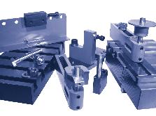


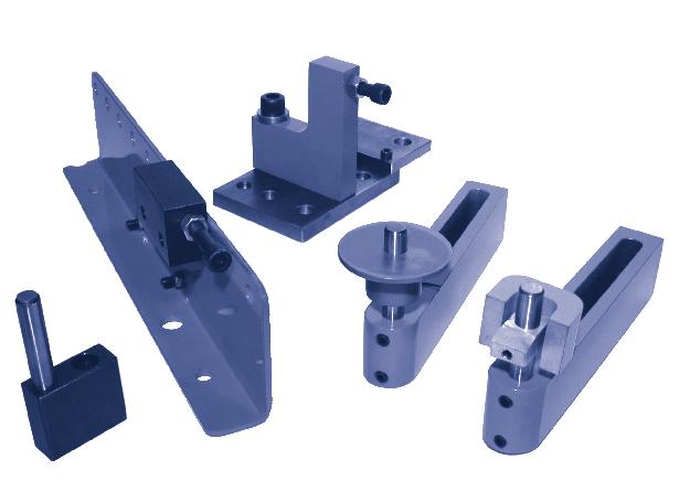

1 MOUNTING ACCESSORIES & ENGINEERING DATA UNITTOOL Punch & Die Company Inc. 1


 C Frame units with 8\" or greater are recommended for use with bedrail.")


2 UNITTOOL MOUNTING ACCESSORIES Ram striker plate RAM STRIKER PLATE PROVIDES ADDITIONAL STRIKING AREA FOR PRESS BRAKE OPERATION Manufactured in 4, 5 and 6 foot lengths. When multiple lengths are used ask for squared ends. (Price on application.) CAT. NO. A B WT.PER FT. RP / RP / RP /2 5 9 RP CAT. NO. BR-800 Bedrail WEIGHT 36# PER FT. FOR USE WITH STRIP TEMPLATE OR BEDRAIL SPACERS. Any template width up to 6" may be used. For template wider than 4 3 /4", remove 3 /8" wide bedrail space bar. Bedrails are manufactured in 4, 6, 8, 10 & 12 foot lengths. When multiple lengths are used, ask for ends to be machined for butting. (Price on application.) C Frame units with 8" depth or greater are recommended for use with bedrail. CAT. NO. BR-801 Bedrail WEIGHT 63# PER FT. FOR USE WITH FORMING DIE, TEMPLATE OR BEDRAIL SPACERS. Eliminates need to remove bedrail for forming operations. Any template up to 6" may be used. For template wider than 4 3 /4", remove 3 /8" wide bedrail spacer bar. Manufactured in 4, 6, 8, 10 & 12 foot lengths. When multiple lengths are used, ask for ends to be machines for butting. (Price on application.) C Frame units with 8" or greater are recommended for use with bedrail. Bedrail spacers CAT. NO. WIDTH FOR USE WITH BRS-807 1" Heavy & Medium Duty Units up to 1 /4" width. BRS /2" Heavy & Medium Duty Units from 1 /4" to 2" width. BRS-809 2" Heavy & Medium Duty Units from 2" to 3" width. BRS /2" Heavy & Medium Duty Units from 3" to 3 1 /2" width. BRS-813 5" Heavy & Medium Duty Units from 3 1 /2" to 5 3 /4" width. BRS-817 8" Heavy & Medium Duty Units from 5 3 /4" to 8" width. BRS /2" Adjustable End Stop - Cat. No. 828 & 829. BRS-812 8" All Series 200 Corner & Edge Notching Units. BRS /2" All Series 100-3x3 & 5x5 Corner Notching Units. For convenient mounting of units on bed rail when template is not used. Spacers can be adjusted along the rail to suit any particular hole pattern. 2
3 A = 1 1 /4" A = 1" H&O DIE SUPPLY, INC sales@hodie.com CAT. NO. WS-821 General purpose stop For use on templates or Tee slotted plates. CAT. NO. WS-818 CAT. NO. WS-819 Dowel pin stop Adjustable Work stop Adjustable work stop sits on plate for template or tee slotted plates. The vertical pin can be removed and the screw can be adjusted for variations in stock dimensions. CAT. NO. WS-820 Spring loaded pick-up pin For relocating from previous pierced hole. FOR H SERIES CAT. NO. HWS-824 FOR M SERIES CAT. NO. MWS-825 For popular use for fixed stop on mounting template Disappearing pin stop For progressive piercing when using edge of sheet for gauging. Fixed pick-up pin For locating from holes previously punched when performing pass along operations. Feed rail and adjustable stop Feed Rail Only FOR H SERIES A = 3 1 /2 FOR M SERIES A = 2 19 / Feed rails are used to support work piece over large spans between punching units. FOR H SERIES CAT. NO. HWS-822 FOR M SERIES CAT. NO. MWS-823 FOR H SERIES CAT. NO. HWS-826 FOR M SERIES CAT. NO. MWS-827 FOR H SERIES A = 3 1 /2 FOR M SERIES A = 2 19 / TRAVEL CAT. NO. HFR-830 CAT. NO. MFR-831 CAT. NO. HFR-8 CAT. NO. MFR-833 Adjustable Stop Only CAT. NO. FRS-834 Adjustable stop For a positive stop location with adjustment feature to compensate for variations in size of work piece. Disc edge stop For end gauging the work piece within the C frame holder. Disc only: Cat. No. Ws-874 Bolt and washer set For template mounting Tee bolt, nut and washer set FOR H SERIES CAT. NO. HWS-824 FOR M SERIES CAT. NO. MWS-825 CAT. NO. WS-873 A = 3"-B = 1 /2-13 CAT. NO. BW 863 FOR MODEL H5 1 /4 & H8 UNITS A = 2 1 /4"-B = 1 /2-13 CAT. NO. BW 842 FOR MODEL M & H UNITS EXCEPT H-5 3 /4, H-8, HH-5 1 /2 & M- 3 /4 A = 2 1 /4"-B = 5/16-18 CAT. NO. BW 8 FOR MODEL M 3 /4 UNIT A = 3 1 /2"-B = 1 /2 CAT. NO. NBW 865 FOR MODEL H5¾ & H8 UNITS A = 3"-B = 1 /2 CAT. NO. NBW 843 FOR MODEL M & H UNITS EXCEPT H-5 3 /4, H-8, HH-5 1 /2 & M- 3 /4 A = 2 1 /2"-B = 5 /16" CAT. NO. NBW 866 FOR MODEL M- 3 /4 UNITS A = 3 1 /2"-B = 1 /2" CAT. NO. NBW 872 SQ. HEAD TEE BOLT SET The base of the tee bolt is designed so it can be dropped into the tee slot at any location. When the nut is tightened, the base of the bolt automatically swings into place for tightening. NBW-872 square head tee bolt must slide in from end of the tee slot. 3
4 Tee slotted plate Unittool s tee slotted plates are used for mounting units in press brakes or stamping presses. When multiple lengths are used ask for ends to be squared. Price on application. Locator pins Width No. of Slots LENGTH AND CATALOG NO Approx. Pounds per Foot of Length 12 6 TSP-1218 TSP-1224 TSP-1230 TSP-1236 TSP-1248 TSP-1260 TSP-1272 TSP TSP-1818 TSP-1824 TSP-1830 TSP-1836 TSP-1848 TSP-1860 TSP-1872 TSP TSP-2424 TSP-2430 TSP-2436 TSP-2448 TSP-2460 TSP TSP-3030 TSP-3036 TSP-3048 TSP-3060 TSP TSP-3636 TSP-38 TSP-3660 TSP Cat. No. A For Use with model LP L - series, M 3 /4 LP M 1 /4 H-1, HP 1, HA 1 LP H 1 /4, HP 1 /4, HA 1 /4 LP M-1 3 /4 LP H 1 /2 - HP 1 /2 - HA 1 /2 LP H 2, HP 2, HA 2, H LP M 2 1 /4 Locator pins are used to set up units on a tee slotter plate or bolster. A sheet metal template is placed on the die section of the unit. The locator is dropped down through the guide to pick up the hole in the template. The unit is then bolted in position. The locator pin is removed and the punch is replaced in the guide. Grind life Punch and die grind life must not exceed the dimension shown. The stripper springs and holder can be severely damaged if punches and dies are used without shims beyond the recommended grind life. See below for shim information. HEAVY-DUTY MEDIUM DUTY MODEL NO. A B C H1 thru H2 4 7 /8 3 /4 HP-1 thru HP /8 2 1 /8 HA-1 thru HA /8 3 /4 H-2 1 / / 3 /4 HP-2 1 / / 2 1 /8 H-3, H-3 1 / / 3 /4 H-5 3 /4 1 7 /8 27 / H / 1 /4 MODEL A B C Punch Ass y Length with Punch Length Die Head w/o Head Height M- 3 / M M-1 1 /4, 1 3 /4, 2 1 / M2 1 /2, M M M M Punch and die shims 1/16" THICKNESS Punch and die life can be extended greatly by use of shims to bring parts up to new length. (For punch and die length when new, see charts above). Punch shims can also be used to lengthen punches in event it is desirable to stagger punching load. ( M series only). PUNCH DIE CATALOG NUMBER FOR MODEL PUNCH NUMBER PS-845 M 3/4 MP 072 PS 846 M 1-1/4 MP 122 PS 847 M 1-3/4 MP 172 PS 848 M 2-1/4 MP 222 PS 849 M 3 MP (FOR PUNCH TIP SIZE UNDER 1.125) PS 850 M 3 MP 302 (FOR PUNCH TIP SIZE OVER 1.125) PS 851 M 5 & H 5-3/4 MP 502 ABC&D PS 852 M 2-1/2 HP 252 PS 853 H 3-1/2 HP 352 CATALOG NUMBER FOR MODEL DIE NUMBER DS 854 M 3/4 MD 073 DS 849 M 1-1/4 MD 123 DS 848 M 1-3/4 MD 173 DS 855 M 2-1/4 MD 223 DS 856 M 3 HD 303 DS 857 M 5 & H 5-3/4 HD 603 DS 858 H 1 & H 1-1/4 HD 123 DS 859 H 1-1/2 HD 153 DS 860 H 2 HD 203 DS 861 H 2-1/2 HD 253 DS 862 H 3-1/2 HD 253
5 Magnetic work stop FULLY ADJUSTABLE RADIALLY & VERTICALLY CAT. NO. MWS 868 Magnetic Work Stops help to insure accurate gauging by eliminating bounce back. Also eliminates the need for the operator to hold work piece against stop during press cycle. Recommended by OSHA. SUITABLE FOR 3-1/2" DIE HEIGHT (Heavy-Duty) or 2-19/ DIE HEIGHT (Medium Duty). Special wrench A Special Wrench designed to drop through slot in upper section of holder for easy access to hex nut on the tee slot bolt when units are on close centers. WRENCH CAT. NO. W. 869 Catalog No. Magnetic Feed Rails Description HFRM-870 Magnetic Feed Rail (Heavy Duty) MFRM-871 Magnetic Feed Rail (Medium Duty) Magnetic work supporting feed rails are now available for use with heavy and medium duty punching and notching systems. This rail virtually eliminates template location and set up time. To release the magnetic force simply lift the magnetic feed rail away from the template or tee slot plate. Compensator caps for H1, H1 1 /4, H1 1 /2 & H2 units. Compensator Caps are used to stagger punching load when available press tonnage is marginal. The caps alter the punch assembly length and cause the punch tips to enter the material at different intervals, thereby reducing the required tonnage accordingly. The disadvantage of using compensator caps is that it overworks the stripping springs because of additional punch assembly length. Caution must be exercised to prevent bottoming. New or full length punches and dies are recommended when using compensator caps in order to keep the press shut height at a maximum. MODEL A B C PART NO. H1, H1 1 /4 1-1/2 1-1/ 1/16 CC /8 CC H1 1 /2 1-3/4 1-9/ 1/16 CC /8 CC H /31 1/16 CC /8 CC CHART TO SHOW HOW DIFFERENT COMBINATIONS CAN BE USED: Material Thickness To Be Punched Compensator Cap Thickness Approx. % of Full Tonnage Reqd Number of Punches Capped 1/16 1/ /2 (50%) 1/8 1/ /2 (50%) 1/8 1/8 50 1/2 (50%) 1/8 1/16 & 1/8 33-1/3 2/3 (66.6%) 1/3 w 1/16" Cap 1/3 w 1/8" Cap 3/16 1/ /2 (50%) 3/16 1/8 50 1/2 (50%) 2/3 (66.6%) 3/16 1/16 & 1/8 33-1/3 1/3 w 1/16" Cap 1/3 w 1/8" Cap 1/4* 1/8 50 1/2 (50%) 1/4* 1/16 & 1/8 40 2/3 (66.6%) 1/3 w 1/16" * Use extreme caution on 1/4" material Cap 1/3 w 1/8" Cap 5
6 Punch adapter guides for H-series Punch Adapter Guides are used to convert a larger unit for use with smaller and less expensive punches. For example:- the HPA-122A punch assembly for the H1¼ unit can be used in the H1½ or H2 unit for punching hole sizes of 7/16" and smaller the HPA-152A punch can be used in the H2 unit for punching hole sizes 5/8" and smaller a savings of 10% to 50% can be realized with this method. The Punch Adapter Guides are available for round or shaped hole punches. The only components required to convert a larger unit for use of smaller punches are: Punch Adapter Guide, Punch and Head Assembly and Stripper Spring. FOR ROUND HOLE UNIT FOR SHAPED HOLE UNIT Punch Adapter Guide Number Adapts Punch Assembly Number For Use with Punch Assembly Max. Punch Tip Dimension Use Stripper Spring Number SHG HPA-122A from H1 1 /4 Holder to H1 1 /2 Holder HPA-122A.4375 HSS-125 SHG HPA-122A from H1 1 /4 Holder to H2 Holder HPA-122A.4375 HSS-125 SHG HPA-152A from H1 1 /2 Holder to H2 Holder HPA-152A.625 HSS-155 SHG K HPA-122K from H1 1 /4K Holder to H1 1 /2K Holder HPA-122K.4375 HSS-125 SHG K HPA-122K from H1 1 /4K Holder to H2K Holder HPA-122K.4375 HSS-125 SHG K HPA-152K from H1 1 /2K Holder to H2K Holder HPA-152K.625 HSS-155 Increased stripping pressure for Heavy-Duty 1", 1 1 /4" & 1 1 /2" units FOR MODEL NUMBER Width of Holder Outside Diameter of Regular Spring Outside Diameter of Oversize Spring Percentage of Increased Pressure Oversize Spring Number Spring Price Oversize Punch Head Number H-1, HA-1 & HP /4 50% HSS-125 HPH-127 H-1, HA-1 & HP /2 170% HSS-155 SPH H-1 1 /4, HA-1 1 /4 & HP-1 1 /4 1 /4 1 /4 1 /2 80% HSS-155 SPH H-1 1 /2, HA-1 1 /2 & HP-1 1 /2 1 /2 1 /2 2 65% HSS-205 SPH See Heavy Duty Price Sheet under H-1 1 /4, H-1 1 /2 & H-2 Illustration shows Model H1 1 /2" with HSS-205 Spring and SPH Punch Head. Increased stripping pressure can be made available by adapting the unit with oversize springs that are larger than standard springs on the outside diameter. Special oversize punch heads are also required to properly center the spring around the punch shank. (The spring and punch head exceed the width of the C frame holder.) Electrical push button punches & dies Dimensions shown are standards listed by Push Button manufacturers. 6 Cutler-Hammer Allen-Bradley Clark General Electric Westinghouse Square-D Westinghouse General Electric Allis Chalmers Furnas Electric General Electric Miniature
7 SHAPED HOLE PUNCHES, DIES & GUIDES Standard Shapes Standard shapes are keyed for both parallel and 90 degree position to the center line of the holder. Semi standard and special shapes SEND SKETCH FOR PRICE QUOTATION NOTE: For Shapes that are not symmetrical specify location of shape in relation to center line of holder so that punches and dies can be properly keyed. Listed below are examples of common special shapes. When ordering, please submit a sketch with dimensions as shown. Also specify material thickness being punched and keying information by (point-x) in relation to the front of the machine. When ordering shaped punches and dies for any keyed holder, specify by placing suffix K after the round hole catalog number. Also forward description and/ or sketch with complete dimensions of shape type and thickness of material to be punched or die size. When ordering keyed punch guides, required for shaped hole missing punching specify by placing the suffix K after the round hole catalog number. EXAMPLE: HP 152 PUNCH (ROUND HOLE HPA 152K SHAPED PUNCH ASS Y.1875 x.375 RECTANGLE EXAMPLE: HP 153 DIE (ROUND HOLE) HPA 153K SHAPED DIE.194 x.381 RECTANGLE EXAMPLE: HP 154 GUIDE (FOR ROUND HOLE PUNCHING) HPA 154K KEYED GUIDE (FOR ROUND & SHAPED HOLE PUNCHING) 7
8 Press brake mounting information Shown below are various mounting arrangements that may be helpful in determining the best method for your application. See Fig. 1 This method requires a template that matches the hole pattern of the part to be punched. The template is placed in the 4-7/8 wide recess of the Bed Rail. Bolting or securing the template to the Bed Rail is not required. The template material is.500" thick cold rolled steel. Any width template from 1" to 4-3/4" may be used to suit the requirement. For template width from 4-3/4" to 6" remove the 3/8" wide keeper bar. The purpose of the 3/8" keeper bar is to provide a 4-7/8" wide retainer space when using Bed Rail Spacer as shown in Figure 2. (See page 1 for Bed Rail Spacers.) The template is produced by drilling and reaming a.375 diameter pilot pin hole for each round hole to be punched in the part. (Pilot pin is on the centerline of each C frame unit.) For shaped hole locations drill and ream for " diameter pilot pins on 1.500" center. For economy reasons a template may be provided with the hole pattern layout of more than one part. In this case the holes are generally color coded or stenciled for easy identification. Illustration to show Template or Base Plate setup with medium duty Punching and Notching units. FIG. 2 Illustration to show Bed Rail No. BR800 or BR801 with Bed Rail Spacer that can be used instead of a template. Spacer can be adjusted along the rail to suit a particular hole pattern. When using this method, we recommend the use of 8" throat units or greater, for maximum front to back adjustment. FIG. 1 FIG. 3 Illustration to show how flanges can be added to the Press Ram to accommodate a wider striking area. (See Fg. 1 for Bed Rail Dimensions) FIG. 4 Illustration to show angle supports to adapt low shut height presses to accommodate Heavy Duty C Frame Units. Not suitable for Medium Duty C Frame Units. FIG. 5 Illustration to show Light Duty Units being mounted on BR100 Bed Rail. See Light Duty Catalog. 8
9 Extruded hole data for # 6, # 8 and # 10 sheet metal screws or machine screws ELECTRICAL KNOCKOUT CONDUIT HOLES FOR #6 SHEET METAL OR MACHINE SCREW FOR #8 SHEET METAL OR MACHINE SCREW METAL THICKNESS B DIA. CAN BE TAPPED FOR MACH. SCREWS 24 Ga..169 No Ga..181 No Ga..193 No Ga..217 Yes Ga..241 Yes.0598 METAL THICKNESS B DIA. CAN BE TAPPED FOR MACH. SCREWS 24 Ga..199 No Ga..211 No Ga..223 No Ga..247 Yes Ga..271 Yes.0598 SINGLE KNOCKOUT Knockout punches and dies can be furnished in standard units or for fabricating type machines. The dies are furnished with a kicker to force the slug out of the die for easy removal of the material. DOUBLE KNOCKOUT CONDUIT SIZE 3 /8 PUNCH SIZE FOR SLIP FIT HOLE 11 /16 PRICE ON APPLICATION FOR #10 SHEET METAL OR MACHINE SCREW METAL THICKNESS B DIA. CAN BE TAPPED FOR MACH. SCREWS 24 Ga..220 No Ga..2 No Ga..244 No Ga..268 Yes Ga..292 Yes /2 7 /8 3 /4 1 1 / /8 1 1 /4 1 3 /4 1 1 / /2 2 1 / /8 3 1 /2 4 1 / / / /4 USE STANDARD UNITS REQUIRE SPECIAL UNITS COUNTERSINK HOLES FOR FLAT HEAD SCREWS SCREW SIZE NO. 6 NO. 8 NO /4" 5 /16" 3 /8" M SERIES UNIT M-1 1 /4 M-1 3 /4 M-1 3 /4 M-1 3 /4 M-2 1 /4 M-2 1 /4 H SERIES UNIT H-1 1 /4 H-1 1 /4 H-1 1 /2 H-1 1 /2 H-2 H-2 METAL THICKNESS 24 ga ga ga ga ga ga ga ga Punch Die Punch Die Punch Die Punch Die Punch Die Punch Die A Dia. A Dia. A Dia. A Dia. A Dia. A Dia
10 General Information TOOL STEELS FOR PUNCHES AND DIES Unittool has standardized on Type O-1 Oil Hardening Tool Steel. This material has performed satisfactorily for most applications. Occasionally, tool steels of other characteristics may be required to suit a particular application. Punches and dies, produced from the tool steels listed below are available ask for quotation. Type M-2 (High Speed) Type D-2 (High Carbon High Chrome) Type A-2 (5% Chrome) Type S-7 (Shock Resistant) PUNCHING INFORMATION The maximum hole size and material thickness for each punching and notching unit is specified in the catalog. The metal thickness refers to SAE mild steel. Other materials may affect the stripping, punching and/or notching ability of the equipment. Refer to tonnage chart on page 12 for tonnage requirement and shear strength of these materials. Listed below is other helpful information. ALUMINIUM, COPPER & BRASS These materials have a low shear strength and therefore cause a drag and galling effect. To help overcome this condition keep punches sharp and lubricate punch and work piece with a kerosene solution. The slugs have a tendency to fuse together when punching soft material. Take caution that slugs do not pile up in slug chutes. It is helpful to decrease die clearance to approximately 75% of mild steel clearance. STAINLESS STEEL The shear strength of stainless steel is approximately 40% to 50% greater than mild steel depending on the physical properties of the material. The capacity of the punching or notching unit must be reduced accordingly. Punches and dies should be sharpened more frequently for good hole quality and also to eliminate tonnage build up due to additional forces required when punches and dies lose their keen cutting edges. RE-ROLLED RAIL STEEL Re-rolled rail steel is one of the most difficult material to punch and notch due to extreme hard spots that cause breakdown of the punch and die cutting edges. In many cases, a particular area may be harder than the punch. The material is unpredictable some parts may punch satisfactorily and other parts may cause excessive punch wear or breakage. Experience has proven that punches produced from M-2 (High Speed) tool steel give the most satisfactory results. Die buttons are generally subject to approximately 50% of the punch wear and therefore Unittool standard Type O-1 oil hardening tool steel generally performs satisfactorily for medium protection. RULE OF THUMB There is definite relationship or ratio that must be maintained between the thickness of material being punched and the minimum punch tip diameter or hole size. The rule of thumb for punching mild steel with a yield or shear strength of 50,000 P.S.I. is that the punch diameter must be equal to or greater than the material thickness to be punched. This of course may be violated under proper conditions. For example: if a press brake or hydraulic press is being used, the shock loads on the punch tips are greatly reduced as the punch enters the material; whereas, high speed mechanical presses create a greater shock load on the punch tip that result in greater failures. Dull punches and dies require greater punching pressure and may result in premature failure. It is helpful in marginal operations to provide the punch tip with a shear ground face which will reduce the punching load on the punch column. Special guided punch tips are also helpful in extending punch life. If material with less yield or shear strength is being punched the thickness to diameter ratio may be altered to as much as 1 to 2, (Example: 1/4" diameter hole in 1/2" material that has a yield strength of 25,000 P.S.I.) or even greater under ideal conditions. If the material has a yield strength of 75,000 P.S.I., the ratio must be reversed to approximately 2 to 1 (Example: 1/2" diameter hole in 1/4" material). MAINTENANCE CHECKLIST Many times production will lag and quality will fall below standard because preventive maintenance has been neglected. It is the little things that develop into major problems which reflect high production costs. Productions costs can be decreased if your punching and notching equipment is properly maintained. You will find the following check list helpful in maintaining best performance of your Unittool equipment. REPLACE WORN SPRINGS!! CHECKLIST A Excessive Burrs Result From: 1. Dull punch and/or die 2. Excessive die clearance 3. Misalignment of C frame holder due to fall or impact 4. Press striker plate or bolster plate out of parallel B Refusal to Strip Results From: NO HAMMERS!! 1. Dull punch and/or die 2. Insufficient die clearance 3. Stock thickness in excess to unit capacity 4. Press shut height below specifications 5. Excessive galling of punch tip 6. Irregular die heights when units are close together will warp material while punching and cause lock up during the stripping action. 7. Damaged stripper spring 8. If punching material with scale or rust the guides may be packed with rust or scale particles that cause the punch to bind in the guide or may cause the guide to hang up in the holder C Spring Breakage Results From: 1. Press shut height too low, causing springs to overstress or bottom D Excessive Punch and/or Die Wear Result From: 1. Holder out of alignment 2. Material being punched has excessive hardness 3. Striker plate is upset or not square to bed of press causing side load, thereby, throwing punch and die into shear E C Frame Holder Out of Alignment Results From: 1. Unit not supported properly 2. Shut height too low, causing unit to bottom and close feed clearance 3. Dirt or grit underneath holder 4. Press ram and bed not parallel 10
11 Frequent Questions WHAT IS SHUT HEIGHT? Shut Height for punching and notching equipment is the distance from the base of the unit to the ram of the press when the punch has entered the die. The Shut Height for a press is defined as the distance between the bed and the ram when the stroke is down. WHAT IS DIE HEIGHT? Die Height is the distance from the base of the punching or notching unit to the top of the die surface. WHAT IS FEED CLEARANCE? Feed Clearance in a unit is the distance between the bottom of the guide and/or holder, and the top of the die when the press stroke is up. WHAT IS DIE CLEARANCE? Die Clearance is the difference in size between the punch and die. For example: if a punch size is.750" diameter and the die size is.762" diameter, it has a total of.012" die clearance (.006" per side). For good hole quality, the die clearance should be increased as the material thickness is increased and vice versa. The recommended die clearance for unitized tooling is as follows: RECOMMENDED DIE CLEARANCE FOR UNITIZED TOOLING Up to 1/16" Thick Mild Steel total over 1/16" to 1/8" Thick Mild Steel total over 1/6" to 3/16" Thick Mild Steel total over 3/16" to 1/4" Thick Mild Steel total over 1/4" to 3/8" Thick Mild Steel total over 3/8" to 1/2" Thick Mild Steel total over 1/2" to 3/4" Thick Mild Steel total The following drawings will show result of proper and excessive die clearance. INSUFFICIENT CLEARANCE PROPER CLEARANCE EXCESSIVE CLEARANCE PENETRATION START OF FRACTURE COMPLETION OF FRACTURE RESULT IN SUBJECT PART 11
12 12 H&O DIE SUPPLY, INC FRACTION AND DECIMAL EQUIVALENTS United States Standard Gauge (REVISED) 1 Manufacturers Standard Gage for Sheet Steel Based on in. per oz. per sq. ft.; in. per lb. per sq. ft. (reciprocal of lb. per sq. ft. per in. thick); in. per lb. per sq. in USEFUL INFORMATION To find circumference of a circle multiply diameter by To find diameter of a circle multiply circumference by To find area of a circle multiply square of diameter by Area of rectangle = length multiplied by breadth. Doubling the diameter of a circle increases its area four times. To find area of a triangle multiply base by 1 /2 perpendicular height. Area of ellipse = product of both diameters x Area of parallelogram = base x altitude. To find side of an inscribed square multiply diameter by or multiply circumference by or divide circumference by Standard Gage No. Thickness Inches Decimal Equivalent Ounces per Sq. Ft. Pounds per Square Inch Pounds per Square Foot Decimal Equivalents of Number Size Drills No. Size of Drill in Inches No. Size of Drill in Inches No. Size of Drill in Inches Decimal Equivalents of Letter Size Drills Letter Size of Drill in Inches Letter Size of Drill in Inches Letter Size of Drill in Inches S L E R K D Q 0.3 J C P 0.3 I B O H A N G M F
13 Drill No. or Letter Inch mm H&O DIE SUPPLY, INC CONVERSION CHART INCH/MM Drill No. or Letter Inch mm Drill No. or Letter Inch mm Drill No. or Letter Inch mm Drill No. or Letter Inch mm N / Y / / / Z / O / / P / / / Q A / / B R / C / / D S E 1/ / / F T G / / / H U / / I / J V / K / W / / L / / M / X /
14 CONVERSION CHART INCH/MM Inch mm Inch mm Inch mm Inch mm Inch mm / / / / / / / / / / / / / / / / / / / / / / / / / / / / / / /
15 TONNAGE CHART APPROXIMATE PRESSURES REQUIRED FOR PUNCHING ROUND HOLES IN MILD STEEL (50,000 P.S.I. YIELD) Metal Gauge HOLE DIAMETER Thickness Inches 1/8".125 3/16" /4".250 5/16" /8".375 7/16" /2".500 9/16" /8".625 PRESSURE IN TONS /" /16" /4" /8" /2" /8" /4" " /16" /4" /16".8125 To obtain tonnage required for punching round holes in mild steel multiply as follows: X DIAMETER OF HOLE X MATERIAL THICKNESS X 25 PUNCHING PRESSURE REQUIRED FOR ONE HOLE TONNAGE CHART APPROXIMATE PRESSURES REQUIRED FOR NOTCHING MILD STEEL 7/8" /16" " METAL THICKNESS Gauge /16" 1/4" 3/8" 1/2" 5/8" 3/4" 1" Decimal TONS REQUIRED TO NOTCH 1" LENGTH Formula for notching mild steel based on 25 tons per square inch: TOTAL SHEAR LENGTH X MATERIAL THICKNESS X 25 = TONNAGE MULTIPLIER CHART THE MULTIPLES SHOWN OPPOSITE MAY BE USED TO CONVERT THE ABOVE CHART AND FORMULA TO FIND TONNAGE REQUIRED TO NOTCH OTHER MATERIAL. FOR EXAMPLE: IT REQUIRES 1.5 TONS TO NOTCH 1" OF 16-GAUGE MILD STEEL STAINLESS STEEL (18-8), WOULD REQUIRE 1.5 X 1.4 (MULTIPLIER) OR 2.1 TONS. MATERIAL DESCRIPTION TONS PER SQ. IN. YIELD or SHEAR STRENGTH PER SQ. IN. MULTIPLIER Aluminium - Soft Sheet 7 1 /2 15,000 P.S.I..30 Aluminium - Half Hard 9 1 /2 19,000 P.S.I..38 Aluminium - Hard 12 25,000 P.S.I..50 Brass - Soft Sheet 15 30,000 P.S.I..60 Brass - Half Hard 17 1 /2 35,000 P.S.I..70 Copper - Rolled 14 28,000 P.S.I..57 Steel - Mild 25 50,000 P.S.I Steel - ASTM-A ,000 P.S.I Steel - 50 Carbon 35 70,000 P.S.I Steel - Cold Drawn 30 60,000 P.S.I Steel - Stainless (18-8) 35 70,000 P.S.I
16 16 d D E d D E d D E 1/4 9/ 5/16 11/ /4 1-9/ 1-5/ / /16 2-3/8 2-7/16 2-1/ /8 13/ 7/16 15/ /8 1-13/ 1-7/ / /16 2-5/8 2-11/16 2-3/ /2 17/ 9/16 19/ /2 1-17/ 1-9/ / /16 2-7/8 2-15/ /8 21/ 11/16 23/ /8 1-21/ 1-11/ / /16 3-1/8 3-3/16 3-1/ /4 25/ 13/16 27/ /4 1-25/ 1-13/ / /16 3-3/8 3-7/16 3-1/ /8 29/ 15/16 31/ /8 1-29/ 1-15/ / /16 3-5/8 3-11/16 3-3/ / 1-1/16 1-3/ / 2-1/16 2-3/ /16 3-7/8 3-15/ /8 1-5/ 1-3/16 1-7/ /8 2-5/ 2-3/16 2-1/ /8 4-1/4 4-3/8 4-1/ Distance across corners of hexagons and squares UNITTOOL D=1.1547d E=1.4142d FORMULA FOR ESTABLISHING C DIMENSION OF RECTANGLE H&O DIE SUPPLY, INC sales@hodie.com
17 1/8 5/ 3/16 7/ 1/4 9/ 5/16 11/ 3/8 13/ 7/16 15/ 1/2 17/ 9/16 19/ 5/8 21/ 11/16 23/ 3/4 25/ 13/16 27/ 7/8 29/ 15/16 31/ 1" 1/ / / / / / / / / / / / / / / DISTANCE ACROSS CORNERS OF SQUARES AND RECTANGLES 19/ / / / / / / / / / / / / " APPROXIMATE SHIPPING WEIGHTS HEAVY DUTY C FRAME UNITS MEDIUM DUTY C FRAME UNITS HEAVY DUTY NOTCHERS Model H Wt. in Lbs. Model HP Wt. in Lbs. Model M Wt. in Lbs. MODEL Wt. in Lbs. 4H-1 9 4HP-1 9 4M- 3 /4 5 SERIES 100 8H HP M- 3 /4 7 H33-LCN 65 12H HP-1 15 H33-RCN 65 4M-1 7 4H-1 1 /4 12 4HP-1 1 /4 12 8M-1 10 H55-LCN 105 8H-1 1 /4 14 8HP-1 1 /4 14 H55-RCN H-1 1 / HP-1 1 /4 17 4M-1 1 /4 9 8M-1 1 /4 12 HV H-1 1 /2 15 4HP-1 1 / M-1 1 /4 15 HV1 1 /2 41 8H-1 1 /2 18 8HP-1 1 / H-1 1 / HP-1 1 /2 21 4M-1 3 /4 15 SERIES H-1 1 / HP-1 1 /2 26 8M-1 3 /4 18 HNC H-1 1 /2 24HP-1 1 /2 12M-1 3 /4 22 HNC M-1 3 /4 26 HNC H HP M-1 3 /4 8H HP-2 24 HNE H HP M-2 1 /4 19 HNE H HP M-2 1 / H HP M-2 1 /4 29 MEDIUM DUTY NOTCHERS 18M-2 1 /4 37 SERIES 100 4H-2 1 /2 29 4HP-2 1 / M-2 1 /4 46 M33-LCN 38 8H-2 1 /2 35 8HP-2 1 /2 28 M33-RCN 38 12H-2 1 / HP-2 1 /2 39 4M-2 1 / H-2 1 /2 53 8M-2 Model HA Wt. in Lbs. /2 26 M55-LCN 54 24H-2 1 / M-2 1 /2 31 M55-RCN 54 4HA M-2 1 /2 41 8H HA M-2 1 /2 50 MV H HA-1 15 MV-1 1 / H M HA-1 1 /4 12 8M-3 29 SERIES 200 8H-3 1 /2 61 8HA-1 1 / M-3 36 MNC H-3 1 / HA-1 1 / M-3 47 MNC H-3 1 / M-3 59 MNC H-3 1 / HA-1 1 /2 15 MNC HA-1 1 / M H-5 3 / HA-1 1 / M-4 42 MISCELLANEOUS UNITS 12H-5 3 / HA-1 1 / M-4 50 L-SERIES- 3 /4 4 3 /4 18H /2 24HA-1 24M H-5 3 /4 186 HCP HA M-5 45 HCP-2 1 / H HA M H HA M-5 68 TP H HA HA M HZP- Model HH Wt. in Lbs. /4 4 18M HZP-1 Model HH Wt. in Lbs. /4 21 8HH-2 1 / M HZP-1 1 / HH-2 1 /2 40 8HH-3 1 /2 53 HZP2 18HH-2 1 / HH-3 1 / HH-3 1 /2 72 8HH-3 12HH HH-5 1 / HH HH-5 1 / HH-5 1 /


18 UNITTOOL Special Application Shown below are a few examples of special unitized hole punching and notching equipment. For your special application, our experienced engineering department will design and quote a method to solve your hole punching requirement. Special application requiring a large feed clearance. Hole punching formed parts. Special cluster units Multiple punch & notch units. Template set up for special aluminum extrusion Special template set up utilizing standard units. For multiple hole piercing on close hole centers
unittool punch & die co., INC. 28XX punches and dies H&O DIE SUPPLY, INC
 CATALOG XX-94 28XX punches and dies unittool punch & die co., INC. Unittool punch & Die 28XX TOOLING TERMS: NET 30 DAYS. F.O.B. OUR PLANT, ST. CATHARINES, ONT. PRICES SUBJECT TO CHANGE WITHOUT NOTICE.
Tu r n y o u r p r e s s b r a k e o r p u n c h p r e s s i n t o a h o l e p u n c h i n g p r o f i t c e n t e r.
 Tu r n y o u r p r e s s b r a k e o r p u n c h p r e s s i n t o a h o l e p u n c h i n g p r o f i t c e n t e r. U n i P u n c h M o d u l a r To o l i n g Works with existing presses Multiple holes
TOOL DESIGN - MANUFACTURING DESIGN SPECIFICATIONS FOR TOOLING AND EQUIPMENT SECTION H - DIE DESIGN TABLE OF CONTENTS. H.1 General...
 TABLE OF CONTENTS H.1 General...Page 2 H.2 General Die Layout...Page 2 H.3 General Die Features...Page 2 H.4 Specific Die Type Features...Page 5 H.5 Special Punches and Die Bushings...Page 6 H.6 Wire E.D.M...Page
Operating Instructions For Lockformer Button Punch Flanger
 Capacity: 20 to 28 Gauge Galvanize Operating Instructions For Lockformer Button Punch Flanger To satisfactorily form the 90º button punch flange on light gauge materials, it was necessary to form the metal
NUMBER 1 Di-Acro Hand Notcher
 OPERATOR S MANUAL & INSTRUCTIONS NUMBER Di-Acro Hand Notcher Di-Acro, Incorporated PO Box 9700 Canton, Ohio 7 373 Progress Street N.E. Canton, Ohio 705 330-55-9 330-55-00 (fax) Revised 0/0 Sale or distribution
Lockformer / 16 Gauge Speednotch
 Lockformer / 16 Gauge Speednotch INSTALLATION PRELIMINARY: After uncrating, locate unit, with or without base skid, to area of operation. Unbind foot switch cord and cylinder hoses and remove gauge pin
Why Use. Stock Ejectors. The New Industry Standard
 Why Use s The New Industry Standard This product may be covered by one or more patents or patent applications. See http://www.standardlifters.com/patents.html for details. 8/14 - Rev. 1 Application - Ejecting
18000 HDL FOUR POST LIFT LB CAPACITY INSTALLATION AND OWNER'S MANUAL
 18000 HDL FOUR POST LIFT 18000 LB CAPACITY INSTALLATION AND OWNER'S MANUAL WARNING! Do not raise a vehicle unless the front stops are in place, the parking brake is set, and the wheels are chocked. Stay
Form No Assembly & Operating Instructions for: SAFETY PRECAUTIONS
 Form No. 0230 Assembly & Operating Instructions for: 833 20300 83 2220 837 0-0008 078 SHOP PRESS Max. Capacity: 2 Ton These instructions are intended for various shop presses. Some models are shipped assembled
Holemaking Products & Accessories
 Holemaking Products & Holemaking Products & Made of top-of-the-line materials for longer lasting performance, Klein's diverse line of drill bits and holemaking products and accessories provide accuracy
Profiform 200 Profiform 320. Operating manual
 Profiform 200 Profiform 320 Operating manual Profiform 200 / Profiform 320 Operating manual Page 1 Table of contents 1. General information Page 2 2. Profile of the Profiform sheet metal working machines
1904, 1904Pg, 1904PgSB, and 1906SB High Capacity Ratchet Knockout Drivers
 INSTRUCTION MANUAL 1904, 1904Pg, 1904PgSB, and 1906SB High Capacity Ratchet Knockout Drivers Read and understand all of the instructions and safety information in this manual before operating or servicing
STAR TOOL SUPPLY / GRAND TOOL SUPPLY
 Made of hardened and tempered tool steel with ground points. es have knurled grip. Set consists of 1 each of 5 punches in plastic pouch. Point Size Length 1/16 3 3040004 5/64 4 3040005 3/32 4 3040006 9/64
Holemaking Products & Accessories
 Holemaking Products & Made of top-of-the-line materials for longer lasting performance, Klein's diverse line of drill bits and holemaking products and accessories provide accuracy and consistency to get
Installation Manual Flat Track Series
 Manual Flat Track Series Contents Safety...1 Parts...2 Hardware.......................................... 2 Tools Required..................................... 4.............................................
Operation, Parts and Maintenance Manual Model Notcher
 Operation, Parts and Maintenance Manual Model 16-18 Notcher 6926 Smithville Hwy. McMinnville, TN 37110 Phone: 931-934-2211 Fax: 931-934-2220 Email info@tennsmith.com www.tennsmith.com Proudly Made in the
OPERATOR S MANUAL Euromac Punch Press Applications
 ROLLER SOLUTIONS Use and Maintenance Instructions OPERATOR S MANUAL Euromac Punch Press Applications ROLLING SHEAR ROLLING RIB ROLLING OFFSET ROLLING PINCHER INDEX I. SAFETY WARNING 2 II. BASIC TOOLING
Fastener Basics. Common Fastener Types. Fastener Materials. Grade / Class and Fastener Strength
 Fastener Basics Common Fastener Types Fastener Grade (US) or Class (metric) refers to the mechanical properties of the fastener material. Generally, a higher number indicates a stronger, more hardened
Operating Instructions
 Operating Instructions Holding the material against the angle gauge slide it into the forming head. Be sure that the material remains against the gauge until work is finished. NOTE: This machine will handle
Design and Analysis of Press Tool Assembly
 Design and Analysis of Press Tool Assembly Raveendra M.Tech Student ABSTRACT Press working may be defined as a chip less manufacturing process by which various components are made from sheet metal. This
Operating, Servicing, and Safety Manual Model # 100 Standard Hydraulic Tubing Notcher Model #100-U Heavy Duty Hydraulic Tubing Notcher
 Operating, Servicing, and Safety Manual Model # 100 Standard Hydraulic Tubing Notcher Model #100-U Heavy Duty Hydraulic Tubing Notcher Model # 100 Standard Model #100-U Heavy Duty CAUTION: Read and Understand
Aluminum Continuous Geared Hinges
 Manufacturing, Inc. Overhead Holders & Stops Hospital Push/Pull Latches Electro-Magnetic Door Holders Electrical Power Transfer Products Stainless Steel Continuous Pin & Barrel Hinges Stainless Steel Edge
MODEL 36 and 52 FOOT SQUARING SHEARS OPERATION, PARTS & MAINTENANCE MANUAL. Proudly Made in the USA
 MODEL 36 and 52 FOOT SQUARING SHEARS OPERATION, PARTS & MAINTENANCE MANUAL Proudly Made in the USA Model 36 and 52 Foot Squaring Shear Parts View 2 Model 36 and 52 Parts List INDEX NO. 36 52 DESCRIPTION
SECTION 3. BOLTS. bolt is a standard AN-type or a special-purpose bolt, and sometimes include the manufacturer.
 9/8/98 AC 43.13-1B SECTION 3. BOLTS 7-34. GENERAL. Hardware is the term used to describe the various types of fasteners and small items used to assemble and repair aircraft structures and components. Only
OPERATION, PARTS & MAINTENANCE MANUAL MODELS HB73-16 HB97-18 HB97-16 HB97-12 HB HB HB HB145-18
 OPERATION, PARTS & MAINTENANCE MANUAL MODELS HB73-16 HB97-18 HB97-16 HB97-12 HB121-18 HB121-16 HB121-14 HB145-18 Proudly Made in the USA 2 3 4 FOREWORD This manual has been prepared for the owner and operators
Di-Acro 36 Power Shear
 OPERATOR S MANUAL & INSTRUCTIONS Di-Acro 36 Power Shear Di-Acro, Incorporated PO Box 9700 Canton, Ohio 44711 3713 Progress Street N.E. Canton, Ohio 44705 330-455-1942 330-455-0220 (fax) Revised 01/02 Sale
TK 1014 A POWER SHEAR
 TIN KNOCKER TK 1014 A POWER SHEAR Parts Diagram & Operating Instructions TAAG INDUSTRIES CORP. 1550 SIMPSON WAY, ESCONDIDO, CA 92029 Tel: (800) 640-0746 Fax: (760) 727-9948 Website: www.tinknocker.com
SMF & MACHINE TOOLS, INC
 SMF & MACHINE TOOLS, INC 800-643-5839 METAL WORKING EQUIPMENT Local 501-897-1110 Fax 501-897-1110 14824 Rockbridge Road Little Rock, AR 72206 www.smfmachinetools.com sales@smfmachinetools.com P II 0 IRONWORKER
METRIC FASTENERS 1520 METRIC FASTENERS
 1520 METRIC FASTENERS METRIC FASTENERS A number of American National Standards covering metric bolts, screws, nuts, and washers have been established in cooperation with the Department of Defense in such
 theartofpressbrake.com http://www.theartofpressbrake.com/wordpress/?page_id=1001 Punch press tooling Tooling Strippers When a hole is punched the body of the tool passes through the material, pushing the
Swivel Hoist Ring RIGGING ACCESSORIES. Color coded to distinguish between UNC (Red) and Metric (Silver) thread types.
 and Metric (Silver) thread types.") RIGGING ACCESSORIES Color coded to distinguish between UNC (Red) and Metric (Silver) thread types. Available in UNC and Metric thread sizes. UNC threads available in sizes from 800 pounds to 100,000 pounds,
RIGGING ACCESSORIES Color coded to distinguish between UNC (Red) and Metric (Silver) thread types. Available in UNC and Metric thread sizes. UNC threads available in sizes from 800 pounds to 100,000 pounds,
SOLUTION BULLETIN KNOCKOUTS 101 DEFINITION
 KNOCKOUTS 101 DEFINITION A knockout is a feature in sheet metal created by punching a slug free of but attached to the sheet with small un-cut areas called tabs. A knockout allows for variation in a part
12912 Farnham Avenue White Bear Lake, Minnesota WILSON WHEEL OPERATOR S MANUAL. for Amada Thick Turret Punch Presses
 12912 Farnham Avenue White Bear Lake, Minnesota 55110 WILSON WHEEL OPERATOR S MANUAL for Amada Thick Turret Punch Presses Rolling Shear Rolling Rib Rolling Offset Rolling Pincher Revised: September 20,
Motorized M3 AX7200 Rotary-Style Gasket Cutter Operating Instructions
 Motorized M3 AX7200 Rotary-Style Gasket Cutter Operating Instructions INTRODUCTION Congratulations! You are the owner of the finest rotary-style gasket cutter in the world. Originally developed and patented
Model: SCD430 SCD640. Installation & Operation Guide P/N SCD640-95
 Model: SCD430 SCD640 Installation & Operation Guide P/N SCD640-95 Model SCD430 and SCD640 Kurt has two Self-Centering vises, a four-inch jaw width (SCD430) and a six-inch jaw width (SCD640). Jaw opening
ENGINEERING STANDARDS SECTION: D TOG-L-LOC V-LOC OVAL-LOC LANCE-N-LOC INFORMATION. Tog-L-Loc. How The Joining Process Works
 Tog-L-Loc Tog-L-Loc is a circular, leakproof joint formed by drawing the metals into a circular "cup'' and then expanding the diameter to form a 360 radial lock below the bottom sheet. How The Joining
Metal Stamping Glossary
 Metal Stamping Glossary Alloy - A substance that has metallic properties and is composed of two or more chemical elements of which at least one is an elemental metal. Annealing - A process involving the
Sheet Metal Tools. by:prem Mahendranathan
 Sheet Metal Tools by: SHEET METAL TOOL KIT SHEET METAL TOOLS Rivet Gun 3/32, 1/8, 5/32, 3/16",Cupped Set Mini Bucking Bar Footed Heel-Toe Bucking Bar Air Tool Oil Mechanics Tool Bag High-Speed Air Drill
PEXTO NO. 137 & NO. 152 FOOT SQUARING SHEAR INSTRUCTIONS AND PARTS IDENTIFICATION
 PEXTO NO. 137 & NO. 152 FOOT SQUARING SHEAR INSTRUCTIONS AND PARTS IDENTIFICATION INSTRUCTIONS FOR ADJUSTING PEXTO FOOT SHEARS -- BEFORE OPERATING -- Remove Shears From Skids and Log in Place 1. This shear
PRO Series Brakes Operating Instructions
 PRO Series Brakes Operating Instructions Tapco Products Company PRO Brake System PRO Cut Off Gauge Simplifies cutting. PRO Cut-Off Quickly, safely, and easily makes factory quality cuts in coil stock,
OPERATION & MAINTENANCE MANUAL
 OPERATION & MAINTENANCE MANUAL AUTOMATIC PECAN CRACKER Food Processing Equipment and Machinery Specializing in the Pecan Industry Mailing: PO Box 817, Mansfield, Louisiana 71052 Located: 280 Independence
FITTING INTRODUCTION:
 FITTING INTRODUCTION: Machine tools are capable of producing work at a faster rate, but there are occasions when components are processed at the bench. Sometimes it becomes necessary to replace or repair
1. Turn off or disconnect power to unit (machine). 2. Push IN the release bar on the quick change base plate. Locking latch will pivot downward.
. 2. Push IN the release bar on the quick change base plate. Locking latch will pivot downward.") Figure 1 Miniature Quick Change Applicators, of the end feed type, are designed to crimp end feed strip terminals to prestripped wires. Each applicator is set up to accept the strip form of certain specific
Figure 1 Miniature Quick Change Applicators, of the end feed type, are designed to crimp end feed strip terminals to prestripped wires. Each applicator is set up to accept the strip form of certain specific
STEEL RULE. Stock TRY SQUARE
 FITTING INTRODUCTION Fitting consists of a handwork involved in fitting together components usually performed at a bench equipped with a vice and hand tools. The matting components have a close relation
Engineering Data Stock Ejectors
 Engineering Data s The New Industry Standard This product may be covered by one or more patents or patent applications. See http://www.standardlifters.com/patents.html for details. 8/14 - Rev. 1 Things
PRO Brake Operating Instructions
 PRO Brake Operating Instructions Tapco Products Company P R O 9 a n d P R O B r a k e s PRO Brake System PRO Cut Off Gauge Simplifies cutting. PRO Cut-Off Quickly, safely, and easily makes factory quality
INSTALLATION INSTRUCTIONS FOR INSTALLING T-SERIES EXTRA HEAVY DUTY LEVER LOCKSET
 HIGH EDGE 2 1/4"(57mm) 03079400070 INSTALLATION INSTRUCTIONS FOR INSTALLING T-SERIES EXTRA HEAVY DUTY LEVER LOCKSET IMPORTANT: THIS LOCK IS NON-HANDED. LOCK IS FACTORY PACKED PREADJUSTED FOR 1³ ₄" (45mm)
OPERATOR S MANUAL MODEL 207 WORK SAFELY AT ALL TIMES WITH QUALIFIED OPERATORS ONLY. QUALIFIED OPERATORS NAME SHIFT DA TE
 OPERATOR S MANUAL WORK SAFELY AT ALL TIMES WITH QUALIFIED OPERATORS ONLY. MODEL SERIAL# We, the undersigned, have read and understand the OPERATOR S MANUAL. QUALIFIED OPERATORS NAME SHIFT DA TE Safety
IN-DIE TAPPING TOOLS TECHNICAL INFORMATION MANUAL
 IN-DIE TAPPING TOOLS TECHNICAL INFORMATION MANUAL CALL TOLL FREE: 1-800-243-2659 FAX: 1-800-833-2659 2004 Danly IEM, A Division of Connell Limited Partnership THIS MANUAL CONTAINS INFORMATION APPLICABLE
NX8 SERIES 6-1/4 HANDRAIL W/ VINYL HANDGRIP
 6-1/4 HANDRAIL W/ VINYL HANDGRIP TYPICAL ASSEMBLY 5 2 BUTT JOINT 12 10 9 1 8 11 6 3 7 4 BUTT JOINT COMPONENT LIST 1 LEFT RETURN 7 UPPER IMPACT ABSORBER 2 RIGHT RETURN 8 LOWER IMPACT ABSORBER 3 OUTSIDE
No. 412, 414, 416 Operations Manual
 No. 412, 414, 416 Operations Manual CARE: Occasional oiling of moving parts with machine oil will ease operation and extend the life of the brake. Occasionally check and tighten the lower beam bracket
Geology, Prospectors, Mining, Metallurgy, Assaying, Environmental, Geotechnical
 LEGEND INC. Geology, Prospectors, Mining, Metallurgy, Assaying, Environmental, Geotechnical 988 Packer Way Sparks, NV 89431 Tel: (786) 786-3003 Fax: (775) 786-3613 Email: info@lmine.com Web: www.lmine.com
Steel Construction Tools
 F o r P Steel Construction Tools r o f e s s i o n a l s. Klein has combined unique design features with skillful engineering and manufacturing to create a superior line of steel construction tools. These
Operating, Servicing, and Safety Manual Model " Foot Shear CAUTION: Read and Understand
 Operating, Servicing, and Safety Manual Model 3000 52" Foot Shear CAUTION: Read and Understand These Operating, Servicing, and Safety Instructions, Before Using This Machine. SAFETY The purpose of the
5/16" Flange nut. Bolt Keeper Plate (8" Sq. SYS.) (3) 1/2" x 3" Hex head connector zinc plated bolt w/ washers and nut. Anchor 3" sq. 7 Ga.
 (3) 1/2 x 3 Hex head connector zinc plated bolt w/ washers and nut. Anchor 3 sq. 7 Ga.") 2 1/2" x 2 1/2" x 10 Ga. 6" 5" 4" Variable Slipbase (8" Sq. SYS.) 5/16 Corner Bolt W/ nut 5/16" Flange nut Stub Insert (8" Sq. SYS.) Bolt Keeper Plate (8" Sq. SYS.) (3) 1/2" x 3" Hex head connector zinc
2 1/2" x 2 1/2" x 10 Ga. 6" 5" 4" Variable Slipbase (8" Sq. SYS.) 5/16 Corner Bolt W/ nut 5/16" Flange nut Stub Insert (8" Sq. SYS.) Bolt Keeper Plate (8" Sq. SYS.) (3) 1/2" x 3" Hex head connector zinc
Wire EDMing One-Piece Stamping Dies
 8 121 Wire EDMing One-Piece Stamping Dies Blanking Die Wire EDM has made it possible to produce high quality dies from one piece of tool steel. This method of producing dies with wire EDM can result in
Rotary Engraving Fact Sheet
 Rotary Engraving Fact Sheet Description Rotary engraving is the term used to describe engraving done with a rotating cutting tool in a motorized spindle. The tool, or cutter, cuts into the surface of the
NX7 SERIES 5-1/2 HANDRAIL
 STORAGE & HANDLING The handrails are shipped unassembled. Upon receipt, immediately check all material for any damage that may have occurred in transit and verify that all of the items and quantities are
A M Supply Co. Metalworking Machinery. Drill Presses Jet Tools J-2221VS 20" Variable Speed Drill Press 115/230V 1Ph
 Drill Presses J-2221VS 20" Variable Speed Drill Press 115/230V 1Ph Part # Style Drills to Center Drilling Cap. Cast Drilling Cap. Mild Distance Column Circle Iron Steel to Spindle 354221 Variable 20" 1-1/4"
SMF & MACHINE TOOLS, INC
 SMF & MACHINE TOOLS, INC 800-643-5839 METAL WORKING EQUIPMENT Local 501-897-1110 Fax 501-897-1110 14824 Rockbridge Road Little Rock, AR 72206 www.smfmachinetools.com sales@smfmachinetools.com C. '..-...p
Complete line of Holemaking Products and Accessories
 Complete line of Holemaking Products and Accessories I N T R O D U C I N G Holemaking Products Klein Tools has expanded our line of Holemaking products. We have added new flexible drill bits and related
Holemaking. FEATURED Products. Slug-Splitter SC (Self-Centering) Knockout Punches NEW. Bi-Metal Hole Saws with Stops. NEW Quick Connect Extensions
 Knockout Punches NEW. Bi-Metal Hole Saws with Stops. NEW Quick Connect Extensions") Year after year, Greenlee delivers holemaking products that are second-to-none in the industry. And today, we offer the most complete line of holemaking solutions for getting through steel, stainless steel,
Year after year, Greenlee delivers holemaking products that are second-to-none in the industry. And today, we offer the most complete line of holemaking solutions for getting through steel, stainless steel,
14824 Rockbridge Road Little Rock, AR Toll Free Fax
 14824 Rockbridge Road Little Rock, AR 72206 Toll Free 800-643-5839 Fax 501-897-4090 www.smfmachinetools.com sales@smfmachinetools.com IRONWORKER STANDARD FEATURES 1. Urethane Stripper Attachment keeps
HAND SHEARS NO. 12 AND NO. 24
 OPERATOR S MANUAL & INSTRUCTIONS HAND SHEARS NO. AND NO. Di-Acro, Incorporated PO Box 9700 Canton, Ohio 7 7 Progress Street N.E. Canton, Ohio 70 0--9 0--00 (fax) Revised 0/0 Sale or distribution of manuals
User's Guide for Tooling
 BTM's Tog-L-Loc and Lance-N-Loc Cross Section of a Lance-N-Loc Tog-L-Loc & Lance-N-Loc are protected by patents in the U.S.A. and most other industrialized nations. Tog-L-Loc & Lance-N-Loc are registered
MobileTrak5 Installation Instructions
 MobileTrak5 Installation Instructions PLEASE OPEN ALL BOXES & CHECK TO MAKE SURE YOU HAVE ALL PIECES REQUIRED READ ALL INSTRUCTIONS BEFORE STARTING Tools Required for Assembly 7/16, 1/2 Wrench Phillips
Cross Peen Hammer. Introduction. Lesson Objectives. Assumptions
 Introduction In this activity plan students will develop various machining and metalworking skills by building a two-piece steel hammer. This project will introduce basic operations for initial familiarization
CHEVY SuperBracket Mounting Kit #0826
 CHEVY SuperBracket Mounting Kit #0826 #1200 SuperGlide (16K) #0800 SuperGlide (20.5K) Gross Trailer Weight (Maximum) Vertical Load Weight (Max. Pin Weight) 16,000 lbs. 4,000 lbs. Gross Trailer Weight (Maximum)
Installation Instructions
 Installation Instructions 000964 Revision F Installation Instructions for PIRIT Read this manual fully prior to starting installation. Call American eating Customer ervice with any questions. What you
OWNERS MANUAL. Model No UTILITY CART
 OWNERS MANUAL Model No. 45-00 UTILITY CART CAUTION: Read Rules for Safe Operation and Instructions Carefully Assembly Operation Maintenance Repair Parts PRINTED IN USA FORM NO. 46274 LOOSE PARTS IN CARTON
ATLANTIS RAIL Contact Information
 ATLANTIS RAIL Contact Information Customer Service (800) 541-6829 (508) 732-9191 Spectrum System Installation Instructions Atlantis Rail s Spectrum System is an easy to install, universal cable railing
Fixed Wall Arm. Installation Guide. Part number Rev E 2012 PolyVision Corporation All rights reserved
 Fixed Wall Arm Installation Guide Part number 2002003-001 Rev E 2012 PolyVision Corporation All rights reserved Table of contents Important Safety Instructions... 3 Overview... 4 Important considerations...
MX8 SERIES 6-1/4 HANDRAIL W/ VINYL HANDGRIP
 6-1/4 HANDRAIL W/ VINYL HANDGRIP TYPICAL ASSEMBLY 5 2 BUTT JOINT 12 10 9 1 8 11 6 3 7 4 BUTT JOINT COMPONENT LIST 1 LEFT RETURN 7 UPPER IMPACT ABSORBER 2 RIGHT RETURN 8 LOWER IMPACT ABSORBER 3 OUTSIDE
INSTALLATION INSTRUCTIONS
 INSTALLATION INSTRUCTIONS HIGH PRESSUE LAMINATE (HPL) TOILET PARTITIONS 1030 TrimLineSeries 1040 DesignerSeries Includes continuous hardware option.65. IMPORTANT: Storage and Handling Information on last
IW SERIES IRONWORKERS DURMA
 IW SERIES IRONWORKERS BETTER PARTS BETTER PROFITS IW SERIES IRONWORKERS STANDARD EQUIPMENT Swing Away Stripper Punching Station Section Cutting Angle Cutting Flat Bar Shearing Notching Twist and Drop Punch
INSTALLATION INSTRUCTIONS
 INSTALLATION INSTRUCTIONS SOLID PHENOLIC TOILET PARTITIONS 1080 DuraLineSeries Class-A Fire Rated Includes Institutional Hardware Option.67 IMPORTANT: Storage and Handling Information on last page. Review
Swivel Hoist Ring Page 142
 Swivel Hoist Ring Page 142 Hoist Rings Color coded to distinguish between UNC (Red) and Metric (Silver) thread types HR-125 M HR-125 Available in UNC and Metric thread sizes. UNC threads available in sizes
TO OPERATE AUTO-GUIDE POWER. 24 Gauge Pittsburgh Operating Instructions FLANGING ATTACHMENT
 24 Gauge Pittsburgh Operating Instructions Holding the material against the angle gauge slide it into the forming head. Be sure that the material remains against the gauge until work is finished. Make
PREMIUM THIN TURRET TOOLING SYSTEM
 Distribuitor: S.C. SM TECH S.R.L. www.smtech.ro www.wilsontool.ro office @ smtech.ro Tel: 0374991480 Tel mob: 0745528494 Fax: 0374091010 PREMIUM THIN TURRET TOOLING SYSTEM Strength. Performance. Innovation.
Operating, Servicing, and Safety Manual Model # & 72 Ultimate Box & Pan Brake
 Operating, Servicing, and Safety Manual Model # 2800 48 & 72 Ultimate Box & Pan Brake CAUTION: Read and Understand These Operating, Servicing, and Safety Instructions, Before Using This Machine. 1-800-467-2464
USER MANUAL & PARTS LIST MODEL 136A S/N:
 NUMBERALL STAMP & TOOL CO., INC. USER MANUAL & PARTS LIST MODEL 136A S/N: P.O. BOX 187, 1 HIGH ST. SANGERVILLE, ME 04479 www.numberall.com office@numberall.com TEL: 207-876-3541 FAX: 207-876-3566 MODEL
MODEL 36 Di-Acro Hand Shear
 OPERATOR S MANUAL & INSTRUCTIONS MODEL 36 Di-Acro Hand Shear Di-Acro, Incorporated PO Box 9700 Canton, Ohio 44711 3713 Progress Street N.E. Canton, Ohio 44705 330-455-1942 330-455-0220 (fax) Revised 01/02
Type XTSR71 Sizes
 (Page 1 of 13) s 494-5258 Type XTSR71 s 494-5258 Figure 1 Thomas XTSR71 Coupling 1. General Information 1.1 Thomas Couplings are designed to provide a mechanical connection between the rotating shafts
Fastener Basics. Common Fastener Types. Fastener Materials. Grade / Class and Fastener Strength
 Fastener Basics Common Fastener Types Fastener Grade (US) or Class (metric) refers to the mechanical properties of the fastener material. Generally, a higher number indicates a stronger, more hardened
Reamer Basics. Fixed Reamers The reamer size is fixed and any size reduction due to wear or sharpening cannot be reclaimed
 1 Reamer Basics Reamers are available in a variety of types, materials, flute styles and sizes The typical reamer is a rotary cutting tools designed to machine a previously formed hole to an exact diameter
INSTALLATION INSTRUCTIONS for the JOMY RETRACTABLE LADDER. If there are any questions, please call (800)
") INSTALLATION INSTRUCTIONS for the JOMY RETRACTABLE LADDER If there are any questions, please call (800) 255-2591 INSTALLATION INSTRUCTIONS WARNING! Ladder Sections Lock When Closed. Do Not Install or Close
INSTALLATION INSTRUCTIONS for the JOMY RETRACTABLE LADDER If there are any questions, please call (800) 255-2591 INSTALLATION INSTRUCTIONS WARNING! Ladder Sections Lock When Closed. Do Not Install or Close
Drill Bits & Hole Saws
 F o r P Drill Bits & Hole Saws r o f e s s i o n a l s. Klein drill bits provide accuracy and consistency for professionals. Made of top-of-the-line materials for longer-lasting performance, Klein drill
Ringblaster Mark IV Maintenance Guide. Version 1.5
 Ringblaster Mark IV Maintenance Guide Version 1.5 WARNING Winchester Industrial Equipment and Loads must be properly stored, handled and maintained for safe and proper function. Mishandling or failure
CertainTeed INSTALLATION GUIDE SIMTEK FENCE PRODUCTS. Fence Installation Guide 3', 4' & 6' High
 CertainTeed INSTALLATION GUIDE SIMTEK FENCE PRODUCTS Fence Installation Guide 3', 4' & 6' High INSTALLATION GUIDE These instructions are designed to assist both professional installers and do-it-yourselfers
PII140 IRONWORKER PII140
 14824 Rockbridge Road Little Rock, AR 72206 Toll Free 800-643-5839 Fax 501-897-4090 www.smfmachinetools.com sales@smfmachinetools.com IRONWORKER 6 1 5 4 2 STANDARD FEATURES 1. Mechanical Stripper Attachment
HANDHOLE SEAT GRINDER
 1041-1601 HANDHOLE SEAT GRINDER OPERATING INSTRUCTIONS & SERVICE MANUAL Rev: A, 9/17/2007 TO REDUCE THE RISK OF INJURY AND EQUIPMENT DAMAGE USER MUST READ AND UNDERSTAND OPERATOR S MANUAL. Thomas C. Wilson,
CONTENTS TOOL LIST U P S I D E I N N O V A T I O N S, L L C RAMP AND STEP SYSTEM ASSEMBLY INSTRUCTIONS. Revised: June 2013
 U P S I D E I N N O V A T I O N S, L L C RAMP AND STEP SYSTEM ASSEMBLY INSTRUCTIONS TOOL LIST Required Tools: - Reciprocating Saw with Metal Cutting Blade - Drill - 7/16 Drill Bit for Metal Drilling -
Crankshaft Gear Modification and Assembly Procedures
 652 Oliver Street Williamsport, PA 17701 U.S.A. Tel. 570-323-6181 Fax. 570-327-7101 www.lycoming.textron.com MANDATORY SERVICE BULLETIN DATE: January 30, 2003 Service Bulletin No. 475C (Supersedes Service
25000 Series Lo-T TM Butterfly Control Valve Instructions
 November 2001 25000 Series Lo-T TM Butterfly Control Valve Instructions Instruction No. 25.1:IM PRELIMINARY STEPS Before installation, note the flow direction arrow on the valve body. The flow should enter
Horizontal and Vertical. Metal Cutting Band Saw MODEL: BS-115
 Horizontal and Vertical Metal Cutting Band Saw MODEL: BS-5 SAFETY. Know your band saw. Read the operator s Manual carefully. Learn the operations, applications and limitation.. Use recommended accessories.
Number Of Holes Chart For Standard Book Length Sheet Size
 RHIN- -TUFF INSTRUCTION BOOK FOR THE EWC-8370, HD-8370, HC-8318 HD-8370 Semi Automatic Wire Inserter/Closer } www.rhin-o-tuff.com HC-8318 Semi Automatic Wire Inserter/Closer AND INTRODUCTION TO OTHER HD
SECTION 7. SAFETYING
 9/8/98 AC 43.13-1B SECTION 7. SAFETYING 7-122. GENERAL. The word safetying is a term universally used in the aircraft industry. Briefly, safetying is defined as: Securing by various means any nut, bolt,
3200 Series Modular Belt Straight Conveyors
 00 Series Modular Belt Straight Conveyors Installation, Maintenance and Parts Manual Flat Modular Belt Conveyor Modular Belt Z-Frame Conveyor Available with: DORNER MFG. CORP. INSIDE THE USA OUTSIDE THE
ENGINEERING STANDARDS SECTION: TOG-L-LOC V-LOC LANCE-N-LOC INFORMATION. Tog-L-Loc. How The Joining Process Works
 Tog-L-Loc Tog-L-Loc is a circular, leakproof joint formed by drawing the metals into a circular "cup'' and then expanding the diameter to form a 360 radial lock below the bottom sheet. How The Joining
Installation and Assembly - Universal Articulating Swivel Double-Arm for 42" - 60" Plasma Screens
 Installation and Assembly - Universal Articulating Swivel Double-Arm for 42" - 60" Plasma Screens Models: PLAV 70-UNL, PLAV 70-UNL-S PLAV 70-UNLP, PLAV 70-UNLP-S R This product is UL Listed. It must be