VARIABLE ANGLE LOCKING HAND SYSTEM
|
|
|
- Alison Cannon
- 6 years ago
- Views:
Transcription


1 VARIABLE ANGLE LOCKING HAND SYSTEM For fragment-specific fracture fixation with variable angle locking and locking technology Instruments and implants approved by the AO Foundation. This publication is not intended for distribution in the USA. SURGICAL TECHNIQUE
2 Image intensifier control This description alone does not provide sufficient background for direct use of DePuy Synthes products. Instruction by a surgeon experienced in handling these products is highly recommended. Processing, Reprocessing, Care and Maintenance For general guidelines, function control and dismantling of multi-part instruments, as well as processing guidelines for implants, please contact your local sales representative or refer to: For general information about reprocessing, care and maintenance of Synthes reusable devices, instrument trays and cases, as well as processing of Synthes non-sterile implants, please consult the Important Information leaflet (SE_023827) or refer to:
3 TABLE OF CONTENTS INTRODUCTION Variable Angle Locking Hand System Overview 2 AO Principles 5 Intended Use and Indications 6 Featured Plates and Technique Highlights 7 Screws in the System 18 Featured Instruments 20 SURGICAL TECHNIQUE Preoperative Planning and Reduction 27 Lag Screw Insertion (Optional) 29 Prepare and Insert Plate 37 Trial Implants 37 Insert Screw 50 Implant Removal 51 PRODUCT INFORMATION Implants 54 Kirschner Wires 63 Instruments 64 Optional Instruments 68 Trial Implants 69 Case Components and Modules 73 Also Available 76 MRI Information 77 Variable Angle Locking Hand System Surgical Technique DePuy Synthes 1


4 VARIABLE ANGLE LOCKING HAND SYSTEM OVERVIEW The DePuy Synthes Variable Angle Locking Hand System consists of plates that are anatomic, procedure-specific, and available in both stainless steel and titanium. The Variable Angle Locking Hand System offers instrumentation to aid in: fracture reduction provisional fixation plate adaptation construct creation Designed for the Surgeon and Patient A dedicated, global surgeon team was integral to the design of this system through extensive consultation and participation in multiple design labs. Surgeon interviews, design and development meetings, and collaboration with key opinion leaders determined the clinical components necessary for the DePuy Synthes Variable Angle Locking Hand System. DePuy Synthes Companies are dedicated to improving patient care. System Snapshot Extensive system of anatomically precontoured plates First to the market with 1.3 mm locking screws for hand plating 1 Forceps that aid in fracture reduction and lag screw application Forceps that aid in plate fixation Self-retaining screwdrivers Plates available in 316L stainless steel and titanium Color-coded instruments 1 DePuy Synthes Companies market analysis of leading orthopaedic companies, conducted May DePuy Synthes Variable Angle Locking Hand System Surgical Technique


5 SYSTEM TECHNOLOGY Variable Angle Locking Technology Variable Angle Locking Plates 1.5 mm and 2.0 mm feature Variable Angle Locking coaxial holes. Four columns of threads in the Variable Angle Locking hole provide four points for threaded locking between the Plate and the Variable Angle Locking Screw to create a fixed-angle construct at the desired screw angle. Variable Angle Locking plate 1.5 holes accept: Variable Angle Locking screws B 1.5 mm Cortex screws B 1.5 mm Locking screws B 1.5 mm. These screws can only be used on-axis Variable Angle Locking plate 2.0 holes accept: Variable Angle Locking screws B 2.0 mm Cortex screws B 2.0 mm Locking screws B 2.0 mm. These screws can only be used on-axis Variable Angle Locking screws can be angled anywhere within a 30 cone Cortex screws B 1.5 mm and 2.0 mm can be used in the plate positioning slots, if present, for traditional compression and fixation Locking Technology Locking plates 1.3 feature locking, coaxial holes. Fully threaded locking holes provide threaded locking between the plate and the locking screw to create a fixed-angle construct Locking plate 1.3 holes accept: Locking screws B 1.3 mm Cortex screws B 1.3 mm Variable Angle Locking Hand System Surgical Technique DePuy Synthes 3
6 Variable Angle Locking Hand System Overview SYSTEM FEATURES Features Extensive range of implant options Anatomically contoured plates Plates designed for lateral and direct dorsal application Low-profile, anatomically precontoured plates Recessed screw heads Variable Angle Locking Technology Benefits Accommodates a variety of fractures and patient sizes Designed with contour to adapt to bony anatomy Accommodates plate placement to help avoid tendon insertion points Designed to reduce soft tissue irritation Designed to sit flush with the plate surface Offers screw placement options in a variety of fragment patterns and around the joint Provides fixed angle stability for metaphyseal and osteopenic bone Elongated plate holes Modular, color-coded system Facilitate plate positioning Aids in clear identification of instruments for Operating Room staff and Central Processing Facilitates proper instrumentation usage by size Comprehensive instrumentation Implants offered in both stainless steel and titanium T4 and T6 self-retaining screwdriver shafts Hex coupling screwdriver handle Reduction Forceps Plate Holding Forceps Aids surgeon in all aspects of procedure: plate adaption, provisional fixation, and bone preparation Allows options for surgeon preference and patient need Aid in screw handling, measuring, and delivery Ergonomic connection mechanism in a handle design that disassembles for cleaning Aids reduction and lag screw application via forceps Holds plate intraoperatively 4 DePuy Synthes Variable Angle Locking Hand System Surgical Technique

7 4 DePuy Synthes Expert Lateral Femoral Nail Surgical Technique AO PRINCIPLES AO PRINCIPLES In 1958, the AO formulated four basic principles, which have become the guidelines for internal fixation. 1, 2 In Those 1958, principles, the AO formulated as applied to four the basic Variable principles, Angle which have Locking become Hand the System, guidelines are: for internal fixation 1, 2. 4_Priciples_03.pdf :08 Anatomic Anatomic reduction reduction Fracture Fracture reduction reduction and and fixation fixation to to restore restore anatomical anatomical relationships. relationships. 1 2 Stable Stable fixation fixation Fracture Fracture fixation fixation providing providing absolute absolute or relative or relative stability, stability, as required as by the required patient, by the the injury, patient, and the the injury, personality and the personality of the fracture. of the fracture. Early, active mobilization Early and safe mobilization and rehabilitation of of the injured part and the patient as as a whole. 4 3 Preservation Preservation of of blood blood supply supply Preservation Preservation of of the the blood blood supply supply to to soft soft tissues tissues and and bone bone by by gentle reduction gentle reduction techniques techniques and and careful careful handling. handling. 1 Müller ME, M Allgöwer, R Schneider, H Willenegger. Manual of Internal Fixation. 3rd ed. Berlin Heidelberg New York: Springer Rüedi TP, RE Buckley, CG Moran. AO Principles of Fracture Management. 1. 2nd Müller ed. Stuttgart, ME, Allgöwer New M, York: Schneider Thieme. R, Willenegger H. Manual of Internal Fixation. 3rd ed. Berlin, Heidelberg, New York: Springer; Rüedi TP, RE Buckley, CG Moran. AO Principles of Fracture Management. 2nd ed. Stuttgart, New York: Thieme; Variable Angle Locking Hand System Surgical Technique DePuy Synthes 5
8 INTENDED USE AND INDICATIONS Intended Use Variable Angle Locking Hand System Implants are intended for temporary fixation, correction or stabilization of bones in anatomical region of the hand. Indications The Variable Angle Locking Hand System is indicated for the treatment of fractures, deformities and degenerative diseases in the hand. Precaution: When using this system to treat skeletally immature patients, physiological status of the physes and individual stature of the patient should be assessed before considering treatment options as damage to the physes may occur, leading to potential growth arrest. 6 DePuy Synthes Variable Angle Locking Hand System Surgical Technique


9 FEATURED PLATES AND TECHNIQUE HIGHLIGHTS The plates contained in this section are featured implants of the DePuy Synthes Variable Angle Locking Hand System. Refer to the product information section for a complete list of all plate configurations offered as part of this system. Phalangeal Head Plate Designed with an anatomic contour and hole configuration to facilitate lateral fixation of fractures of the middle and proximal phalangeal head. Elongated hole for adjustment of plate position Ulnar or radial plate placement Curved plate designed to follow the natural curve of the phalanx Screw configuration in the head is designed to span the attachment of the collateral ligament Available in Right and Left orientations Designed for periarticular fractures and articular fractures of the distal phalanx Available sizes: Left Right 1.3 mm mm = Stainless Steel 04 = Titanium Left Right Surgical Approach Ulnar Radial Right Hand Right Plate Left Plate Left Hand Left Plate Right Plate Variable Angle Locking Hand System Surgical Technique DePuy Synthes 7


 Place screw in most volar hole (4) Confirm placement and depth of screws under radiographic imaging Place")
10 Featured Plates and Technique Highlights When implanting this plate, the following screw order placement is suggested. Place a cortex screw in the elongated hole (1), leaving the screw slightly loose. Screw placement is at the midaxial line. Place plate prior to the K-wire so that the cortex screw can be positioned at the midaxial line Provisionally fix the condyles. Place a K-wire in the center of the condyle, so the wire is located between the two distal holes (2). The K-wire should be placed in the center of the axis of the joint. K-wire placement is relative to the fan-shaped, central collateral ligament. Note that the footprint of the ligament is larger than the center of the axis. Make small adjustments to K-wire placement to avoid intra-articular placement of screws, while still creating a stable construct. Variations in K-wire placement are at surgeon s discretion, considering periarticular tissue and fracture size. For Plates 1.3, use a K-wire B 0.6 mm. For plates 1.5, use a K-wire B 0.8 mm Adjust the plate along the bone shaft, as necessary, so that the K-wire abuts the plate. Tighten the cortex screw in the elongated hole Place a screw in most distal hole (3) Place screw in most volar hole (4) Confirm placement and depth of screws under radiographic imaging Place remaining screws in the head and plate shaft, depending on fracture pattern Refer to surgical technique section for general plate and screw application techniques where this suggested screw insertion order can be applied. 8 DePuy Synthes Variable Angle Locking Hand System Surgical Technique

. For plates 1.3, place a locking screw.")
11 Phalangeal Base Plate Designed with an anatomic contour and hole configuration to facilitate fixation of fractures at the base of the middle and proximal phalanx. Elongated hole for adjustment of plate position Lateral or dorsal placement Designed for metaphyseal transverse, oblique, or comminuted fractures of the phalanx When implanting this plate, the following screw order placement is suggested. Place cortex screw in elongated hole (1), leaving screw slightly loose. Check alignment and adjust plate as necessary Tighten screw in the elongated hole. Place a Variable Angle Locking Screw in one of the head holes (2). For plates 1.3, place a locking screw. Confirm screw placement and depth under radiographic imaging Place remaining screws in the head and plate shaft as needed, depending on fracture pattern Available sizes: 1.3 mm 1.5 mm 2.0 mm = Stainless Steel 04 = Titanium 2 1 Refer to surgical technique section for general plate and screw application techniques where this suggested order can be applied. Variable Angle Locking Hand System Surgical Technique DePuy Synthes 9

, leaving screw slightly loose. Check alignment and adjust plate, as necessary. Tighten the screw in the elongated hole.")
12 Featured Plates and Technique Highlights Condylar Plate Straight plate with hole configuration designed to facilitate fixation of the middle and proximal phalanx, and the metacarpals. Elongated hole for adjustment of plate position Lateral or dorsal placement Designed for metaphyseal transverse, oblique, or comminuted fractures of the phalanx and metacarpals Position the head of the plate on the condyles. Available sizes: 1.5 mm 2.0 mm = Stainless Steel 04 = Titanium 2 1 When implanting this plate, the following screw order placement is suggested. Place a cortex screw in the elongated hole (1), leaving screw slightly loose. Check alignment and adjust plate, as necessary. Tighten the screw in the elongated hole. Place a Variable Angle Locking screw in one of the head holes (2). Confirm screw placement and length using radiographic imaging. Place remaining screws in the head and plate shaft as needed, depending on fracture pattern Refer to surgical technique section for general plate and screw application techniques where this suggested order can be applied. 11 DePuy Synthes Variable Angle Locking Hand System Surgical Technique

13 Metacarpal I Plate, Dorsal Designed with an anatomic contour and hole configuration to facilitate fixation in fractures of the base of MC I. Elongated hole for adjustment of plate position Dorsal placement on MC I with the wide end of the plate placed proximally Three K-wire holes B 1.0 mm accept K-wires B 1.0 mm or smaller, for provisional fixation 4 variable angle screw holes in head designed to facilitate capture of fracture fragments Variable Angle Locking Plate 1.5 has higher strength than a non-locking straight plate 2.0 mm* Available sizes: 1.5 mm 2.0 mm = Stainless Steel = Titanium 3 1 Proximal 2 Distal Position plate on the metacarpal. During plate placement, consider the curve in the base of the metacarpal. Place a K-wire in any of the three K-wire holes, if needed, to hold the plate in place and obtain provisional fixation of the fragments around the joint (1). When implanting this plate, the following screw order placement is suggested: Place cortex screw in the elongated hole (2), leaving the screw slightly loose. Adjust plate position, as necessary. Tighten cortex screw in the elongated hole. Place a Variable Angle Locking Screw in the most proximal, metaphyseal head hole (3). The screw in the most proximal head hole is placed first since it is closest to the joint. Confirm screw placement and length under radiographic imaging. Place remaining screws in the head and plate shaft as needed, depending on the fracture pattern Refer to surgical technique section for general plate and screw application techniques where this suggested order can be applied. * Benchtop testing may not be indicative of clinical performance. Testing on file at DePuy Synthes Companies. Testing was completed comparing the Metacarpal I Plate 1.5, Dorsal to the DePuy Synthes non-locking straight plate 2.0 mm. Variable Angle Locking Hand System Surgical Technique DePuy Synthes 11

 Available in left and right orientations Y-shape with contourable arms to fit varying anatomy and address fracture fragments Designed for T- or Y-shaped")

, leaving the screw slightly loose. Adjust plate position, as necessary. Tighten cortex screw in the elongated hole.")
14 Featured Plates and Technique Highlights Metacarpal I Plate, Lateral Designed with a shape and hole configuration to facilitate fixation in MC I fractures. This plate is designed to be contoured to fit the dorsal and radial periarticular surfaces. Elongated hole for adjustment of plate position. Elongated hole is positioned on the shaft Designed for palmar approach to MC I Lateral placement on MC I (radiopalmar) Plate adaptation is recommended to ensure correct fit of plate to the bone (see technique section related to plate contouring) Available in left and right orientations Y-shape with contourable arms to fit varying anatomy and address fracture fragments Designed for T- or Y-shaped fractures in the sagittal plane and comminuted intra-articular fractures of the base of the first metarcarpal. Placement of the plate is fracture-dependent. When implanting this plate, the following screw order and placement is suggested: Ensure plate is contoured to fit anatomy, prior to implantation. The more contoured arm of the plate is positioned so that it wraps around the bone palmarly. This contoured arm follows the curve of the shaft of the plate. Place a cortex screw in the elongated hole (1), leaving the screw slightly loose. Adjust plate position, as necessary. Tighten cortex screw in the elongated hole. Place a Variable Angle Locking screw in the arms of the plate (2). Confirm screw placement and length under radiographic imaging. Place remaining screws in the plate, depending on fracture pattern. Available size: 1.5 mm Left Right = Stainless Steel 04 = Titanium Left 2 2 Right Refer to surgical technique section for general plate and screw application techniques where this suggested order can be applied. 11 DePuy Synthes Variable Angle Locking Hand System Surgical Technique

, leaving the screw slightly loose.")
 in the distal portion of the plate to hold the plate in place, as necessary Place a Variable")
15 Metacarpal Neck Plate Designed with an anatomic contour and hole configuration to facilitate fixation of the head and neck of the metacarpals. Elongated hole for adjustment of plate position MC V: ulnar placement MC II-IV: dorsolateral placement K-wire B 1.0 mm hole accepts K-wires B 1.0 mm or smaller, for provisional fixation 4 diverging screws for secure fixation Designed for unstable subcapital and comminuted head and neck fractures of the metacarpals Available size: 1.5 mm = Stainless Steel = Titanium When implanting this plate, the following screw order placement is suggested: Place a cortex screw in the elongated hole (1), leaving the screw slightly loose. Adjust plate position, as necessary. Tighten cortex screw in the elongated hole Additionally, a K-wire can be placed in the K-wire hole (2) in the distal portion of the plate to hold the plate in place, as necessary Place a Variable Angle Locking Screw in the either of the most distal holes of the plate head (3). Avoid wire and screw interference when placing screws in a variable angle hole. If necessary, the K-wire can be bent slightly to facilitate placement of the Variable Angle Drill Guide into a plate hole in the head of the plate Variable Angle Locking Hand System Surgical Technique DePuy Synthes 11


 in head of plate.")
16 Featured Plates and Technique Highlights Confirm screw placement and length under radiographic imaging Place remaining screws in the plate, depending on fracture pattern. Fracture pattern will dictate the order of screw placement Refer to surgical technique section for general plate and screw application techniques where this suggested order can be applied. Variable Angle Screws at nominal angle in head of plate. Variable Angle Screws at 15 angulation (distally) in head of plate. 11 DePuy Synthes Variable Angle Locking Hand System Surgical Technique


17 Rotation Correction Plate Designed with an anatomic contour and hole configuration to facilitate fixation of the metacarpals and phalanges. Elongated transverse hole for intraoperative adjustment of the reduction, including correction of the fragment rotation of the bone, if necessary. Elongated hole allows 2.5 mm of travel Design of the plate head facilitates contouring to the anatomy of the condyles Designed for fractures and osteotomies of the metacarpals and phalanges Available sizes: 1.5 mm 2.0 mm = Stainless Steel = Titanium 1 2 When implanting this plate, the following screw order placement is suggested: Position the plate with the T-shaped section of the plate near the joint Insert 2 Variable Angle Locking Screws into the T-shaped section of the plate (1), ensuring that the elongated hole (2) is on the side of the osteotomy away from the joint, near a section of intact bone. Confirm screw placement and length under radiographic imaging Adjust the position of the bone Place a cortex screw into the elongated transverse hole (2), leaving the screw loose. Release and tighten the cortex screw while adjusting plate position, as necessary Check result of repositioning with the wrist at maximum extension. Tighten cortex screw Place remaining screws distal or proximal to the elongated transverse hole. Confirm screw placement and depth using radiographic imaging Variable Angle Locking Hand System Surgical Technique DePuy Synthes 11


18 Featured Plates and Technique Highlights Refer to surgical technique section for general plate and screw application techniques where this suggested order can be applied. 11 DePuy Synthes Variable Angle Locking Hand System Surgical Technique


19 Rotation Correction Fracture Plate Designed for indirect reduction techniques where bridging or in-situ reduction is desired. Allows adjustment of rotation and angulation before fixed angle construct is applied. Consistent with AO indirect reduction techniques of external fixation 1,2 Two elongated holes for intra-operative correction in 2 planes Dorsal placement Staggered shaft Designed for crushed, multifragmented, and/or periarticular fractures of the metacarpals and phalanges Available sizes: 1.5 mm 2.0 mm = Stainless Steel = Titanium 1 2 When implanting this plate, the following screw order placement is suggested: Insert a cortex screw into the head of the plate (1) into the condyle, ensuring that the elongated hole (2) is on the side of the osteotomy away from the joint, near a section of intact bone. Provisional fixation in either adjacent hole may be helpful Correct the position of the bone. Place a cortex screw in the elongated transverse hole (2) Continue to adjust the position of the bone, as necessary Check result of repositioning Place remaining screws distal or proximal to the elongated transverse hole Refer to surgical technique section for general plate and screw application techniques where this suggested order can be applied. 1. Müller ME, Allgöwer M, Schneider R, Willenegger H. Manual of Internal Fixation. 3 rd ed. Berlin, Heidelberg, New York: Springer; Rüedi TP, RE Buckley, CG Moran. AO Principles of Fracture Management. 2 nd ed. Stuttgart, New York: Thieme; Variable Angle Locking Hand System Surgical Technique DePuy Synthes 11
20 SCREWS IN THE SYSTEM Screws with B 1.3 mm Locking Screws 1.3 mm Only for on-axis insertion in the locking holes Threaded, conical head locks securely into the locking hole Self-retaining,T4 Stardrive recess Self-tapping tip facilitates insertion Cortex Screws 1.3 mm Can be used in locking holes to compress the plate to the bone Self-retaining,T4 Stardrive recess Self-tapping tip facilitates insertion Screws with B 1.5 mm Variable Angle Locking Screws 1.5 mm Threaded, rounded head locks securely into the Variable Angle Locking hole Purple, color-coded head to easily distinguish as Variable Angle Locking Screw Self-retaining, T4 Stardrive recess Blunt self-tapping tip Cortex Screws 1.5 mm Can be used in the Variable Angle Locking holes to compress the plate to the bone Self-retaining, T4 Stardrive recess Self-tapping tip facilitates insertion Also Available Locking Screws, Stardrive, B 1.5 mm only used on-axis Compatible with Variable Angle Locking Plate 1.5 mm 11 DePuy Synthes Variable Angle Locking Hand System Surgical Technique


21 Screws with B 2.0 mm Variable Angle Locking Screws 2.0 mm Threaded, rounded conical head locks securely into the locking hole Purple, color-coded head to easily distinguish as a Variable Angle Locking Screw Self-retaining, T6 Stardrive recess Blunt, self-tapping tip Cortex Screws 2.0 mm Can be used in the Variable Angle Locking holes to compress the plate to the bone Self-retaining, T6 Stardrive recess Self-tapping tip facilitates insertion Also Available Locking Screws, Stardrive, B 2.0 mm only used on-axis Compatible with Variable Angle Locking Plate 2.0 mm Variable Angle Locking Hand System Surgical Technique DePuy Synthes 11
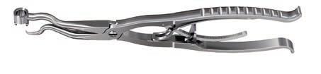
 This instrument is designed to hold reduced metacarpal and phalangeal bone fragments in place, while allowing insertion of a lag screw through")


22 FEATURED INSTRUMENTS Reduction Forceps for Cortex Screws ( ) This instrument is designed to hold reduced metacarpal and phalangeal bone fragments in place, while allowing insertion of a lag screw through the barrel of the forceps. Colors on the drill sleeves indicate the screw size and color bands indicate the threaded and gliding hole. Plate Holding Forceps with Pointed Ball Tip ( ) The plate holding forceps are designed to hold the plate in the desired position against the bone. The ball on the upper portion of the jaws inserts through the plate hole to the bone, and the lower arm is inserted beneath the soft tissue against the underside of the bone The forceps can then be closed to the desired tightness to hold the plate, and is designed to remain in place after the handles are released 22 DePuy Synthes Variable Angle Locking Hand System Surgical Technique


23 Plate Holder ( ) The plate holder is designed to hold the plates. The arms are squeezed together and inserted into a single plate hole. Once the arms are released, they hold the plate via tension The arms of the plate holders can also be placed in two adjacent holes The forceps can also be used to hold the outside edges of the plate. If used to hold the outside of the plate, releasing the arms of the holder will allow the plate to disengage. Variable Angle Locking Hand System Surgical Technique DePuy Synthes 22
 The cutting pliers for locking plates are designed to cut all plates within the variable Angle Locking Hand System.")
24 Featured Instruments Cutting Pliers for Locking Plates 1.3 and VA Locking Plates 1.5 and 2.0 ( ) The cutting pliers for locking plates are designed to cut all plates within the variable Angle Locking Hand System. A rasp for manual deburring is provided on the plate cutter head, if deburring is needed after cutting Cutting Pliers, In-Line, for Locking Plates 1.3 and VA Locking Plates 1.5 and 2.0 ( ) The cutting pliers, in-line for plates are designed to cut plates with straight shafts within the Variable Angle Locking Hand System. Variable Angle Locking and Locking Plate holes are inserted over the insertion posts to hold the plate in place A rasp for manual deburring feature is provided on the plate cutter head, if deburring is needed after cutting 22 DePuy Synthes Variable Angle Locking Hand System Surgical Technique

 Bending pliers facilitate additional contouring of the")
 Bending Pins facilitate additional contouring of 1.")
25 Bending Pliers for Locking Plates 1.3 and VA Locking Plates 1.5 and 2.0 ( , ) Bending pliers facilitate additional contouring of the plates, if necessary. Bending Pins for Locking Plates 1.3 ( ) Bending Pins facilitate additional contouring of 1.3 mm plates, if necessary. Variable Angle Locking Hand System Surgical Technique DePuy Synthes 22

26 Featured Instruments Handle for Screwdriver with Hexagonal Coupling ( ) The design of the handle reduces the likelihood of rolling on a flat surface. The hex coupling provides a one-step, reliable connection when inserting the screwdriver shaft. The handle disassembles into three pieces for cleaning and sterilization. The three parts include the hex coupling with spring, the shaft, and the handle. Stardrive Screwdriver Shafts ( , ) Self-retaining screwdrivers aid in screw handling, measuring, and delivery. Screws with B 1.3 and 1.5 mm feature a T4 Stardrive recess. The tip of the T4 screwdriver is gold-colored. Screws with B 2.0 mm feature a T6 Stardrive recess. 22 DePuy Synthes Variable Angle Locking Hand System Surgical Technique
 Variable angle technique using the cone-shaped end. Nominal angle technique using the fixed-angle end marked coaxial.")
27 Variable Angle Drill Guide coaxial and conical ( , ) The VA Drill Guide, coaxial and conical, is designed for variable angle technique (cone-shaped end) and nominal angle technique (coaxial). Variable Angle Nominal Angle (Coaxial) Variable angle technique using the cone-shaped end. Nominal angle technique using the fixed-angle end marked coaxial. Variable Angle Locking Hand System Surgical Technique DePuy Synthes 22

.")

28 Featured Instruments Variable Angle Drill Guide coaxial and freehand useable ( , ) The VA Drill Guide, coaxial and freehand useable is designed for variable angle technique and nominal angle technique (coaxial). Variable Angle Nominal Angle (Coaxial) Variable angle technique using the variable angle end, which allows freehand angulation of the drill bit. Nominal angle technique using the fixed-angle end marked coaxial. 22 DePuy Synthes Variable Angle Locking Hand System Surgical Technique
29 PREOPERATIVE PLANNING AND REDUCTION 1 Preparation Complete preoperative radiographic assessment and preoperative planning. Select the implant according to the fracture pattern and anatomy of the bone. Note: Ensure the proper plate selection is available, including L (left) or R (right) plates. Left plates are designed for the left hand. Right plates are designed for the right hand. For clarification on right and left Phalangeal Head Plate application, see information on page 7. Variable Angle Locking Hand System Surgical Technique DePuy Synthes 22
 292.100/492.100 Kirschner Wire B 1.0 mm with trocar tip, length 150 mm (stainless steel or titanium) 292.")
30 Preoperative Planning and Reduction 2 Reduce Fracture Instruments / Kirschner Wire B 0.6 mm with trocar tip, length 70 mm, (stainless steel or titanium) / Kirschner Wire B 0.8 mm with trocar tip, length 70 mm (stainless steel or titanium) / Kirschner Wire B 1.0 mm with trocar tip, length 150 mm (stainless steel or titanium) / Kirschner Wire B 1.25 mm with trocar tip, length 150 mm (stainless steel or titanium) Reduce fracture under imaging. The reduction method will depend on patient anatomy and fracture pattern. Optional instrument Reduction Forceps for Cortex Screws B 1.3 to 2.0 mm, soft lock, length 140 mm 22 DePuy Synthes Variable Angle Locking Hand System Surgical Technique
. The associated drill sleeves and drill bits use a color-coded stripe system. The colors on the drill sleeves and drill bits correspond to the screw size.")
31 LAG SCREW INSERTION (OPTIONAL) LAG SCREW INSERTION REDUCTION FORCEPS 1 Select a Drill Sleeve and Drill Bit Lag screws may be inserted using the Reduction Forceps for Cortex Screws B 1.3 to 2.0 mm ( ). The associated drill sleeves and drill bits use a color-coded stripe system. The colors on the drill sleeves and drill bits correspond to the screw size. A single stripe indicates that the drill sleeve or drill bit is used for a threaded hole (pilot hole); a double stripe indicates that the drill sleeve or drill bit is used for a gliding hole. Screw Size Color Coding for Instruments Drill Guide Insert for Threaded Hole Drill Bit for Threaded Hole (One Color Stripe)* Drill Guide Insert for Gliding Hole Drill Bit for Gliding Hole (Two Color Stripes)* 1.3 mm Yellow 1.0 mm mm 1.3 mm mm 1.5 mm Red 1.1 mm mm 1.5 mm mm 2.0 mm Blue 1.5 mm mm 2.0 mm mm * Drill bits are available with various couplings, including Mini Quick Coupling, Jacobs Chuck, and J-Latch. Variable Angle Locking Hand System Surgical Technique DePuy Synthes 22


32 Lag Screw Insertion (Optional) Lag Screw Insertion Reduction Forceps 2 Assemble Drill Guide Insert To Forceps Press the drill guide insert into the barrel of the reduction forceps so that the guide is fully seated and a click is felt. 3 Attach The Reduction Forceps To The Bone Once in place, close the reduction forceps to the desired tightness. The forceps is designed to remain in place after the handles are released. 33 DePuy Synthes Variable Angle Locking Hand System Surgical Technique

33 4 Drill Threaded and Gliding Hole Gliding Hole Threaded Hole Threaded Hole Drill the far fragment using a drill bit for the threaded hole and the corresponding drill guide insert. Gliding Hole Drill the near cortex, so that the thread of the screw does not obtain purchase, using a drill bit for the gliding hole and the corresponding drill guide insert. Drill so that the lag screw is perpendicular to the fracture plane. An alternative technique is to drill for the gliding hole first and then drill for the threaded hole. Variable Angle Locking Hand System Surgical Technique DePuy Synthes 33
 to the handle for screwdriver. Countersink, if desired. 6 Measure Insert the Depth Gauge for Screws B 1.3 to 2.0 mm (03.130.")
34 Lag Screw Insertion (Optional) Lag Screw Insertion Reduction Forceps 5 Countersink (Optional) Remove the drill guide insert from the forceps. Attach the Countersink for Screws B 1.3 to 2.0 mm ( ) to the handle for screwdriver. Countersink, if desired. 6 Measure Insert the Depth Gauge for Screws B 1.3 to 2.0 mm ( ) through the barrel of the forceps, to determine the screw length needed. The depth gauge is designed for one-handed use. 33 DePuy Synthes Variable Angle Locking Hand System Surgical Technique


35 The black line indicates the screw length. Optional Technique Use the scale on the back of the depth gauge to measure for screw length. Note: the depth gauge consists of 2 pieces and is designed to be disassembled for cleaning. Slide the tip of the hook so it is fully inside the black outer body. Press the tab on the back of the sliding hook and remove it from the black outer body. Variable Angle Locking Hand System Surgical Technique DePuy Synthes 33


36 Lag Screw Insertion (Optional) Lag Screw Insertion Reduction Forceps 7 Insert Cortex Screw Instruments Screwdriver Shaft Stardrive 1.3/1.5, T4, self-holding, for Hexagonal Coupling Screwdriver Shaft Stardrive 2.0, T6, self-holding, for Hexagonal Coupling Assemble the screwdriver shaft to the handle for screwdriver. For 1.3 mm and 1.5 mm screws, use the Screwdriver Shaft Stardrive 1.3/1.5, T4 ( , with yellow and red bands). The tip of the T4 screwdriver is coated in gold-color. For 2.0 mm screws, use the Screwdriver Shaft Stardrive 2.0, T6 screwdriver shaft ( , with blue band). The screwdriver and screws are designed to be self holding. To attach the screw to the screwdriver, position the screwdriver directly in line with the screw with no tilting. Ensure that the screwdriver tip engages the star-shaped lobes of the recess in the screw. It may be necessary to rotate the screwdriver up to a quarter turn to fully align the lobes of the screwdriver tip with the lobes of the screw recess. In addition, a tactile sensation may be noticed when the tip of the screwdriver shaft is fully aligned with the screw recess. Apply firm axial pressure downwards to ensure that the screw is fully seated before removing the screw from the implant module. Using the screwdriver, place the screw on the scale of the implant module, to confirm the length of the screw. Insert the screw through the barrel of the reduction forceps. Confirm screw placement under radiographic imaging. Once the screw has been inserted, remove the forceps from the bone. Note: Prior to sterilization of the reduction forceps, soft lock, add one drop of DePuy Synthes Autoclavable Oil ( ) to instrument joints and ratchet mechanisms. 33 DePuy Synthes Variable Angle Locking Hand System Surgical Technique
37 LAG SCREW INSERTION DOUBLE DRILL GUIDE (OPTIONAL) Instruments Double Drill Guide 1.3/ Double Drill Guide 1.5/ Double Drill Guide 2.0/1.5 For cortex screws B 1.3, 1.5 and 2.0 mm used as independent lag screws, use a double-ended drill guide and corresponding drill bit. Drill bits and drill guides are color-coded. Drill bits are available with several different couplings (see item listing). Etch lines on drill bits are spaced 5 mm apart. A K-wire may be used through the double drill guide. Screw Size Color Coding for Instruments Double Drill Guide Drill Bit For Threaded Hole (One Color Stripe)* Drill Bit for Gliding Hole (Two Color Stripes)* 1.3 mm Yellow mm 1.3 mm 1.5 mm Red mm 1.5 mm 2.0 mm Blue mm 2.0 mm * Drill bits are available with various couplings, including Mini Quick Coupling, K-wire, and J-Latch. Variable Angle Locking Hand System Surgical Technique DePuy Synthes 33
38 Lag Screw Insertion Double Drill Guide (Optional) For cortex screws B 1.0 used as independent lag screws, use a drill bit B 0.8 mm (green band) and drill bit B 1.0 mm. Insert the screws using the Screwdriver Shaft 1.0, cruciform, with holding sleeve, with Hexagonal Coupling ( ). Instruments Drill Bit B 0.8 mm, length 64/33 mm, for Pilot Hole, for Jacobs Chuck Drill Bit B 0.8 mm, length 56/16 mm, 2-flute, for J-Latch Coupling Drill Bit B 0.8 mm, length 40/16 mm, 2-flute, for Mini Quick Coupling Screwdriver Shaft 1.0, cruciform, with holding sleeve, with Hex Coupling 33 DePuy Synthes Variable Angle Locking Hand System Surgical Technique
. Place the trial implant on the bone. Trial Implants are etched with the position of screw holes.")
39 PREPARE AND INSERT PLATE Trial Implants (Optional) To determine plate type and size intra-operatively, select a trial implant. Trial implants are available for most plates in the system (see complete list on pages 69 72). Place the trial implant on the bone. Trial Implants are etched with the position of screw holes. K-wire holes are located on the trial implant between the screw holes for provisional fixation of the trial implant. The trial implants include an elongated slot or round hole, which can be used with the Plate Holding Forceps ( ) for placement. After coupling, remove trial implant and K-wires. Warning: Do not bend or cut trial implants. Do not implant trial implants. Variable Angle Locking Hand System Surgical Technique DePuy Synthes 33


40 Prepare and Insert Plate 1 Trim Plate Instrument Cutting Pliers for Locking Plates 1.3 and VA Locking Plates 1.5/2.0 If desired, plate cutting pliers can be used to adjust the length of the plate. The Cutting Pliers ( ) are designed to cut all plates within the Variable Angle Locking Hand System. Note: To prevent sharp edges from causing soft tissue irritation, place the plate top side up on the cutters to ensure any sharp edges will angle towards the underside of the plate. Trim the plate to the desired length using the cutting pliers, and remove any burr by using the rasp on the side of the cutting pliers. The cutting pliers create a straight cut. Remove any burr by using the rasp on the side of the cutting pliers. 33 DePuy Synthes Variable Angle Locking Hand System Surgical Technique


 prior to cleaning and sterilization. The cutting pliers, in-line, create a cut with a rounded profile.")
41 Optional instrument Cutting Pliers, In-Line, for Locking Plates 1.3 and VA Locking Plates 1.5/2.0 Cut portion of plate The Cutting Pliers, In-Line ( ) are designed to cut plates with straight shafts within the Variable Angle Locking Hand System. Note: When using the cutting pliers, in-line, insert the plate top side up in its respective color coded area on the cutting pliers. This is to ensure that the plate holes are protected during cutting. Insert the plate so that the section of the plate to be implanted is located on the side that is color-coded. Ensure that the plate is correctly inserted on the post. These cutting pliers are designed to be used to cut straight shafts of plates within the Variable Angle Locking Hand System. Note: The cutting pliers are designed with 2 silicone inserts in the jaws to hold the cut segment of the plate after cutting. The cutting pliers, in-line are designed with 1 silicone insert. Remove the silicone insert(s) prior to cleaning and sterilization. The cutting pliers, in-line, create a cut with a rounded profile. Remove any burr by using the rasp on the side of the cutting pliers. Variable Angle Locking Hand System Surgical Technique DePuy Synthes 33


42 Prepare and Insert Plate 2 Contour Plate If necessary, contour the plate to fit the patient s anatomy. Instruments Bending Pliers for Locking Plates 1.3 and VA Locking Plates 1.5/2.0, right Bending Pliers for Locking Plates 1.3 and VA Locking Plates 1.5/2.0, left Bending Pin for Locking Plates 1.3, with thread Bend using adjacent holes in the plate. Orient the bending pliers so the side etched UP is facing up, with the top of the plate also facing up. Precaution: Reverse bending or use of the incorrect instrumentation for bending may weaken the plate and lead to premature plate failure (e.g. breakage). Do not bend the plate beyond what is required to match the anatomy. 44 DePuy Synthes Variable Angle Locking Hand System Surgical Technique

. Reverse or sharp bends may weaken the plate and lead to premature plate failure.")
43 Optional The Bending Pin for Locking Plates 1.3 ( ) are designed to be used with the 1.3 mm locking plates. Bend adjacent holes in the plates. Precaution: Avoid reverse bends and sharp bends (sharp bends include a single out-of-plane bend between two adjacent holes of >30 ). Reverse or sharp bends may weaken the plate and lead to premature plate failure. Variable Angle Locking Hand System Surgical Technique DePuy Synthes 44
 292.100/ Kirschner Wire B 1.0 mm with trocar tip, 492.")

44 Prepare and Insert Plate 3 Position Plate Instruments / Kirschner Wire B 0.6 mm with trocar tip, length 70 mm (stainless steel and titanium) / Kirschner Wire B 0.8 mm with trocar tip, length 70 mm (stainless steel or titanium) / Kirschner Wire B 1.0 mm with trocar tip, length 150 mm (stainless steel or titanium) Position the plate over the reduced fracture using the preferred positioning method. Either K-wires or forceps may be used to hold the plate in place. K-wires can be used in the plate K-wire holes, if present. Optional instrument Plate Holding Forceps with pointed ball tip As an alternative, the plate holding forceps with pointed ball tip may be used to hold the plate to the bone. Insert the ball portion through a plate hole to the bone. The curved arm wraps around the underside of the bone through the incision. Close the forceps to the desired tightness to hold the plate. The forceps is designed to remain in place after the handles are released. Precaution: When using the plate holding forceps with pointed ball tip, avoid the tendons and avoid applying excessive pressure. Note: Prior to sterilization of the plate holding forceps with pointed ball tip, add one drop of DePuy Synthes Autoclavable Oil ( ) to instrument joints and ratchet mechanisms. For more information, refer to the Featured Instrument section. 44 DePuy Synthes Variable Angle Locking Hand System Surgical Technique
45 4 Determine Screw Type Depending on the individual case, cortex screws or Variable Angle Locking/Locking Screws may be inserted. Locking or cortex screws can be used in any of the screw holes, with the exception of the nonthreaded elongated hole, if present. The elongated hole is designed for adjustment of plate position. The elongated hole accepts cortex screws only. Leave the cortex screw slightly loose in the elongated hole while adjusting plate position, as necessary. Tighten the cortex screw once plate placement has been confirmed. If a combination of locking and cortex screws is planned, a cortex screw should be inserted first to pull the plate to the bone. If a locking screw is inserted first, ensure that the plate is held securely to the bone, to avoid spinning the plate as the screw is locked in place. Variable Angle Locking Hand System Surgical Technique DePuy Synthes 44
46 Prepare and Insert Plate 5 Drill Instruments For Screws with B 1.3 mm Drill Bit B 1.0 mm, length 75/31 mm, for Pilot Hole, for Jacobs Chuck Drill Bit B 1.0 mm, length 61/31 mm, for Pilot Hole, for J-Latch Coupling Drill Bit B 1.0 mm, length 61/31 mm, for Pilot Hole, for Mini Quick Coupling For Screws with B 1.5 mm Drill Bit B 1.1 mm, length 70/39 mm, for Pilot Hole, for Jacobs Chuck Drill Bit B 1.1 mm, length 65/39 mm, for Pilot Hole, for J-Latch Coupling Drill Bit B 1.1 mm, length 56/39 mm, for Pilot Hole, for Mini Quick Coupling For Screws with B 2.0 mm Drill Bit B 1.5 mm, length 88/57 mm, for Pilot Hole, for Jacobs Chuck Drill Bit B 1.5 mm, length 83/57 mm, for Pilot Hole, for J-Latch Coupling Drill Bit B 1.5 mm, length 74/57 mm, for Pilot Hole, for Mini Quick Coupling Select a drill bit based on the size of the screw. Drill bits are color-coded to the size of the associated screw. Note: The fracture pattern will dictate the optimal screw placement. Screw Size Drill Bit Size/Color Code 1.3 mm 1.0 mm Yellow 1.5 mm 1.1 mm Red 2.0 mm 1.5 mm Blue Fracture pattern will determine the order of screw insertion. In all cases, make sure the plate is in the correct position and flush with the bone. If placing a plate on the condyle, be cognizant of reducing and restoring the articular surface. 44 DePuy Synthes Variable Angle Locking Hand System Surgical Technique
47 6 Select a Drill Guide and Drilling Technique VA Drill Guide, coaxial and conical ( , ) Variable Angle Locking Screws can be inserted using 2 different techniques, depending on which end of the drill guide is used: Verify the drill bit angle and depth under radiographic imaging to ensure the desired angle has been achieved. If necessary, drill at a different angle and verify again under imaging. Precaution: Avoid redrilling, especially in osteopenic bone. Variable Angle Nominal Angle (Coaxial) Variable angle technique using the cone-shaped end. Fully insert the variable angle end of the drill guide into the Variable Angle Locking hole. When drilling, the tip of the drill guide should remain fully seated in the hole Nominal angle technique using the fixed-angle end marked coaxial. Fully insert the coaxial end of the drill guide into the Variable Angle Locking hole and drill. Drill the hole with the drill bit at the desired angle within the cone by positioning the drill bit. Precaution: When using the variable angle end of the guide, it is important to not angulate more than 15 from the central axis of the screw hole. Overangulation could result in difficulty locking the screw. Variable Angle Locking Hand System Surgical Technique DePuy Synthes 44


48 Prepare and Insert Plate Drill for Variable Angle Screws Freehand VA Drill Guide, coaxial and freehand useable ( , ) Variable Angle Locking Screws can be inserted using 2 different techniques, depending on which end of the drill guide is used: Verify the drill bit angle and depth under radiographic imaging to ensure the desired angle has been achieved. If necessary, drill at a different angle and verify again under imaging. Avoid redrilling, especially in osteopenic bone. Variable Angle Nominal Angle Variable angle technique using the variable angle. Nominal angle technique using the fixed-angle end marked coaxial. Fully insert the variable angle end of the drill guide into the Variable Angle Locking hole. Fully insert the coaxial end of the drill guide into the Variable Angle Locking hole and drill. Drill the hole with the drill bit at the desired angle by positioning the drill guide in the hole. Precaution: When using the variable angle end of the guide, it is important to not angulate more than 15 from the central axis of the screw hole. Over angulation could result in difficulty locking the screw. 44 DePuy Synthes Variable Angle Locking Hand System Surgical Technique

 is available for use with")


 to drill for cortex screws")
49 A Drill Sleeve 1.3, with thread, for Drill Bits B 1.0 mm ( ) is available for use with only the plates 1.3. The drill guide allows drilling in the nominal position in the locking hole. Use a Double Drill Guide ( , , or ) to drill for cortex screws through the plate. Variable Angle Locking Hand System Surgical Technique DePuy Synthes 47
 to determine screw length.")

50 Prepare and Insert Plate 7 Determine Screw Length Use the Depth Gauge for Screws B 1.3 to 2.0 mm ( ) to determine screw length. Screw length is indicated by the black line. See pages for additional technique information for the depth gauge. 44 DePuy Synthes Variable Angle Locking Hand System Surgical Technique

. The screwdriver shafts and screws are designed to be self holding.")

51 8 Insert Screw Instruments Screwdriver Shaft Stardrive 1.3/1.5, T4, self-holding, for Hexagonal Coupling Screwdriver Shaft Stardrive 2.0, T6, self-holding, for Hexagonal Coupling Handle for Screwdriver, with Hexagonal Coupling Assemble the screwdriver shaft to the handle for screwdriver. Screws B 1.3 and 1.5 mm are inserted with a screwdriver shaft Stardrive T4 (yellow and red bands). The tip of the screwdriver is coated in gold-color. Screws B 2.0 mm are inserted with a screwdriver shaft Stardrive T6 (blue band). The screwdriver shafts and screws are designed to be self holding. To attach the screw to the screwdriver, position the screwdriver directly in line with the screw, with no tilting. Ensure that the screwdriver tip engages the star-shaped lobes of the recess in the screw. It may be necessary to rotate the screwdriver up to a quarter turn to fully align the lobes of the screwdriver tip with the lobes of the screw recess. In addition, a tactile sensation may be noticed when the tip of the screwdriver shaft is fully aligned with the screw recess. Apply firm axial pressure downwards to ensure that the screw is fully seated before removing the screw from the implant module. Using the screwdriver, place the screw on the scale of the implant module, to confirm the length of the screw. Insert screw. Variable Angle Locking Hand System Surgical Technique DePuy Synthes 44


52 INSERT SCREW When inserting screws, use a two-finger tightening technique. For Variable Angle Locking and Locking Screws, confirm screw placement and length under radiographic imaging prior to final tightening. For Variable Angle Locking and Locking Screws, screw insertion is complete when the screw is flush to the plate. Confirm screw position and depth under radiographic imaging. Precaution: Avoid penetrating the articular surface. Postoperative Treatment Postoperative treatment with locking plates or Variable Angle Locking Plates does not differ from conventional internal fixation procedures. 55 DePuy Synthes Variable Angle Locking Hand System Surgical Technique
53 IMPLANT REMOVAL If removal of the implant is necessary, the following instructions are suggested. 1 Preoperative Planning To ensure that the appropriate screw removal instruments are obtained, the surgeon should have the following information before implant removal: Implant type Time of implantation Material (steel, titanium) Recess geometry and dimension of screws Any visible damage to the implant (eg, broken screw shaft) 2 Clean Recess Instrument Sharp Hook, length 155 mm Before removing screws, clean the screw recess. Free the screw recess from ingrown bone and tissue using the sharp hook to ensure the screwdriver can be fully inserted. Check the condition and the geometry of the recess of the exposed screwhead. Variable Angle Locking Hand System Surgical Technique DePuy Synthes 51

54 Implant Removal 3 Implant Removal Instruments Screwdriver Shaft 1.0, cruciform, with holding sleeve, with Hexagonal Coupling Screwdriver Shaft Stardrive 1.3/1.5, T4, self-holding, for Hexagonal Coupling Screwdriver Shaft Stardrive 2.0, T6, self-holding, for Hexagonal Coupling Handle for Screwdriver, with Hexagonal Coupling Optional set Extraction Set for Standard Screws To remove locking screws, first unlock all screws from the plate; then remove the screws completely from the bone. The last screw removed should be a nonlocking screw on the shaft. This prevents the plate from spinning when locking screws are removed. Note: To remove broken screws or screws with a damaged screw recess, please refer to the DePuy Synthes Screw Extraction Set Application Notes for removal instructions. 55 DePuy Synthes Variable Angle Locking Hand System Surgical Technique
55 SUMMARY TABLE INSTRUMENTS Screw Size Cortex B 1.0 mm Cortex B 1.3 mm Cortex B 1.5 mm Cortex B 2.0 mm Gliding Hole Threaded Hole Gliding Hole (Two Stripes) 1.0 mm 1.3 mm 1.5 mm 2.0 mm Drill Bit Threaded Hole (One Stripe) 0.8 mm 1.0 mm 1.1 mm 1.5 mm Drill Guide Double Drill Guide for Cortex Screws n/a (1.3/1.0 mm) (1.5/1.1 mm) (2.0/1.5 mm) For Variable Angle Locking, Locking, or Cortex Screws through the plate Cortex B 1.0 mm Locking or Cortex Screws B 1.3 mm Variable Angle Locking or Cortex Screws B 1.5 mm Variable Angle Locking or Cortex Screws B 2.0 mm n/a Drill Bit 1.0 mm 1.1 mm 1.5 mm Variable Angle Double Drill Guide with Cone n/a (1.1 mm) (1.5 mm) Drill Guide Variable Angle Double Drill Guide Freehand (1.1 mm) (1.5 mm) Threaded Drill Guide n/a n/a Double Drill Guide for Cortex Screws n/a (1.3/1.0 mm) (1.5/1.1 mm) (2.0/1.5 mm) Screwdriver Cruciform T4 Stardrive T6 Stardrive Depth Gauge Variable Angle Locking Hand System Surgical Technique DePuy Synthes 55
56 PLATES Locking Plates Stainless Steel and TiCP Titanium* Plate Thickness: 0.75 mm Stainless Steel Titanium Locking Plate 1.3, 6 holes, straight, length 24 mm Locking Plate 1.3, 12 holes, straight, length 48 mm Locking T-Plate 1.3, head 3 holes, shaft 5 holes, length 26 mm Locking Y-Plate 1.3, head 3 holes, shaft 5 holes, length 27 mm Locking Phalangeal Base Plate 1.3, head 2 holes, shaft 5 holes, length 26 mm Locking Phalangeal Head Plate 1.3, right, length 22 mm Locking Phalangeal Head Plate 1.3, left, length 22 mm Locking Strut Plate 1.3, 8 holes, oblique-angled, right, length 19 mm Locking Strut Plate 1.3, 8 holes, oblique-angled, left, length 19 mm Locking Web Plate 1.3, 14 holes, length 29 mm * Available nonsterile or sterile-packed. Add S to catalog number to order sterile product. 55 DePuy Synthes Variable Angle Locking Hand System Surgical Technique
57 Variable Angle Locking Plates L Stainless Steel and TiCP Titanium* Plate Thickness: 1.0 mm Stainless Steel Titanium VA Locking Plate 1.5, 6 holes, straight, length 28 mm VA Locking Plate 1.5, 12 holes, straight, length 57 mm VA Locking T-Plate 1.5, head 3 holes, shaft 7 holes, length 40 mm VA Locking Y-Plate 1.5, head 3 holes, shaft 7 holes, length 42 mm VA Locking Phalangeal Base Plate 1.5, head 2 holes, shaft 6 holes, length 36 mm VA Locking Condylar Plate 1.5, head 2 holes, shaft 6 holes, length 36 mm VA Locking Phalangeal Head Plate 1.5, right, length 26 mm VA Locking Phalangeal Head Plate 1.5, left, length 26 mm VA Locking Strut Plate 1.5, 8 holes, oblique-angled, right, length 23 mm VA Locking Strut Plate 1.5, 8 holes, oblique-angled, left, length 23 mm VA Locking Strut Plate 1.5, 12 holes, rectangular, length 36 mm VA Locking Web Plate 1.5, 14 holes, length 33 mm * Available nonsterile or sterile-packed. Add S to catalog number to order sterile product. Variable Angle Locking Hand System Surgical Technique DePuy Synthes 55

58 Plates Stainless Steel Titanium VA Locking Strut Plate 1.5, 4 holes, rectangular, length 11 mm VA Locking Plate 1.5, for Metacarpal I, dorsal, length 29 mm VA Locking Plate 1.5, for Metacarpal I, lateral, right VA Locking Plate 1.5, for Metacarpal I, lateral, left VA Locking Rotation Correction Plate 1.5, head 2 holes, shaft 6 holes, length 33 mm VA Locking Rotation Correction Fracture Plate 1.5, length 32 mm VA Locking Metacarpal Neck Plate 1.5, length 29 mm 55 DePuy Synthes Variable Angle Locking Hand System Surgical Technique


59 Variable Angle Locking Plates L Stainless Steel and TiCP Titanium* Plate Thickness: 1.3 mm Stainless Steel Titanium VA Locking Plate 2.0, 6 holes, straight, length 35 mm VA Locking Plate 2.0, 12 holes, straight, length 71 mm VA Locking T-Plate 2.0, head 3 holes, shaft 7 holes, length 50 mm VA Locking Y-Plate 2.0, head 3 holes, shaft 7 holes, length 52 mm VA Locking Phalangeal Base Plate 2.0, head 2 holes, shaft 6 holes, length 44 mm VA Locking Condylar Plate 2.0, head 2 holes, shaft 6 holes, length 44 mm VA Locking Strut Plate 2.0, 12 holes, rectangular, length 45 mm VA Locking Strut Plate 2.0, 4 holes, rectangular, length 13 mm VA Locking Plate 2.0, for Metacarpal I, dorsal, length 32 mm VA Locking Rotation Correction Plate 2.0, holes, length 41 mm VA Locking Rotation Correction Fracture Plate 2.0, length 42 mm * Available nonsterile or sterile-packed. Add S to catalog number to order sterile product. Variable Angle Locking Hand System Surgical Technique DePuy Synthes 55
60 SCREWS Cortex Screws B 1.0 mm, Self-Tapping, Cruciform* 316L Stainless Steel and TiCP Titanium Stainless Steel Titanium Length (mm) * Available nonsterile or sterile-packed. Add S to catalog number to order sterile product. 55 DePuy Synthes Variable Angle Locking Hand System Surgical Technique
61 Cortex Screws B 1.3 mm, Self-Tapping, T4 Stardrive Recess* 316L Stainless Steel and Titanium Alloy** Stainless Steel Titanium Length (mm) Locking Screws B 1.3 mm, Self-Tapping, T4 Stardrive Recess* 316L Stainless Steel and Titanium Alloy** Stainless Steel Titanium Length (mm) * Available nonsterile or sterile-packed. Add S to catalog number to order sterile product. ** Ti-6Al-7Nb Variable Angle Locking Hand System Surgical Technique DePuy Synthes 55
62 Screws Cortex Screws B 1.5 mm, Self-Tapping, T4 Stardrive Recess* 316L Stainless Steel and Titanium Alloy** Stainless Steel Titanium Length (mm) * Available nonsterile or sterile-packed. Add S to catalog number to order sterile product. ** Ti-6Al-7Nb 66 DePuy Synthes Variable Angle Locking Hand System Surgical Technique
63 Variable Angle Locking Screws B 1.5 mm, Self-Tapping, T4 Stardrive Recess* 316L Stainless Steel and Titanium Alloy** Stainless Steel Titanium Length (mm) * Available nonsterile or sterile-packed. Add S to catalog number to order sterile product. ** Ti-6Al-7Nb Variable Angle Locking Hand System Surgical Technique DePuy Synthes 66
64 Screws Cortex Screws B 2.0 mm, Self-Tapping, T6 Stardrive Recess* 316L Stainless Steel and Titanium Alloy** Stainless Steel Titanium Length (mm) Variable Angle Locking Screws B 2.0 mm, Self-Tapping, T6 Stardrive Recess* 316L Stainless Steel and Titanium Alloy** Stainless Steel Titanium Length (mm) * Available nonsterile or sterile-packed. Add S to catalog number to order sterile product. ** Ti-6Al-7Nb 66 DePuy Synthes Variable Angle Locking Hand System Surgical Technique
65 KIRSCHNER WIRES Kirschner Wire B 0.6 mm with trocar tip, length 70 mm, Stainless Steel, pack of 10 units Kirschner Wire B 0.8 mm with trocar tip, length 70 mm, Stainless Steel, pack of 10 units Kirschner Wire B 0.8 mm with trocar tip, length 150 mm, Stainless Steel, pack of 10 units Kirschner Wire B 1.0 mm with trocar tip, length 150 mm, Stainless Steel, pack of 10 units Kirschner Wire B 1.25 mm with trocar tip, length 150 mm, Stainless Steel, pack of 10 units Kirschner Wire B 0.6 mm with trocar tip, length 70 mm, Titanium Alloy (TAV) Kirschner Wire B 0.8 mm with trocar tip, length 70 mm, Titanium Alloy (TAV) Kirschner Wire B 0.8 mm with trocar tip, length 150 mm, Titanium Alloy (TAV) Kirschner Wire B 1.0 mm with trocar tip, length 150 mm, Titanium Alloy (TAV) Kirschner Wire B 1.25 mm with trocar tip, length 150 mm, Titanium Alloy (TAV) Variable Angle Locking Hand System Surgical Technique DePuy Synthes 66
66 INSTRUMENTS Drill Bit B 0.8 mm, length 64/33 mm, for Pilot Hole, for Jacobs Chuck Drill Bit B 0.8 mm, length 56/16 mm, 2-flute, for J-Latch Coupling Drill Bit B 0.8 mm, length 40/16 mm, 2-flute, for Mini Quick Coupling Drill Bit B 1.0 mm, length 75/31 mm, for Pilot Hole, for Jacobs Chuck Drill Bit B 1.0 mm, length 61/31 mm, for Pilot Hole, for J-Latch Coupling Drill Bit B 1.0 mm, length 61/31 mm, for Pilot Hole, for Mini Quick Coupling Drill Bit B 1.3 mm, length 60/29 mm, for Gliding Hole, for Jacobs Chuck Drill Bit B 1.3 mm, length 55/29 mm, for Gliding Hole, for J-Latch Coupling Drill Bit B 1.3 mm, length 46/29 mm, for Gliding Hole, for Mini Quick Coupling Drill Bit B 1.1 mm, length 70/39 mm, for Pilot Hole, for Jacobs Chuck Drill Bit B 1.1 mm, length 65/39 mm, for Pilot Hole, for J-Latch Coupling Drill Bit B 1.1 mm, length 56/39 mm, for Pilot Hole, for Mini Quick Coupling 66 DePuy Synthes Variable Angle Locking Hand System Surgical Technique

67 Drill Bit B 1.5 mm, length 62/31 mm, for Gliding Hole, for Jacobs Chuck Drill Bit B 1.5 mm, length 57/31 mm, for Gliding Hole, for J-Latch Coupling Drill Bit B 1.5 mm, length 48/31 mm, for Gliding Hole, for Mini Quick Coupling Drill Bit B 1.5 mm, length 88/57 mm, for Pilot Hole, for Jacobs Chuck Drill Bit B 1.5 mm, length 83/57 mm, for Pilot Hole, for J-Latch Coupling Drill Bit B 1.5 mm, length 74/57 mm, for Pilot Hole, for Mini Quick Coupling Drill Bit B 2.0 mm, length 71/41 mm, for Gliding Hole, for Jacobs Chuck Drill Bit B 2.0 mm, length 66/41 mm, for Gliding Hole, for J-Latch Coupling Drill Bit B 2.0 mm, length 57/41 mm, for Gliding Hole, for Mini Quick Coupling Handle for Screwdriver, with Hexagonal Coupling Screwdriver Shaft 1.0, cruciform, with holding sleeve, with Hexagonal Coupling Screwdriver Shaft Stardrive 1.3/1.5, T4, self-holding, for Hexagonal Coupling Variable Angle Locking Hand System Surgical Technique DePuy Synthes 66

68 Instruments Screwdriver Shaft Stardrive 2.0, T6, self-holding, for Hexagonal Coupling Drill Sleeve 1.3, with thread, for Drill Bits B 1.0 mm Double Drill Guide 1.3/ VA Drill Guide, coaxial and conical, for Drill Bits B 1.1 mm VA Drill Guide, coaxial and freehand useable, for Drill Bits B 1.1 mm Double Drill Guide 1.5/ VA Drill Guide, coaxial and conical, for Drill Bits B 1.5 mm VA Drill Guide, coaxial and freehand useable, for Drill Bits B 1.5 mm Double Drill Guide 2.0/ DePuy Synthes Variable Angle Locking Hand System Surgical Technique


69 Depth Gauge for Screws B 1.3 to 2.0 mm, measuring range to 43 mm Countersink for Screws B 1.3 to 2.0 mm, for Hexagonal Coupling Plate Holder Bending Pliers for Locking Plates 1.3 and VA Locking Plates 1.5/2.0, right Bending Pliers for Locking Plates 1.3 and VA Locking Plates 1.5/2.0, left Cutting Pliers, In-Line, for Locking Plates 1.3 and VA Locking Plates 1.5/ Cutting Pliers for Locking Plates 1.3 and VA Locking Plates 1.5/ Silicone Insert for Cutting Pliers, In-Line, Silicone Insert for Cutting Pliers Variable Angle Locking Hand System Surgical Technique DePuy Synthes 67


70 OPTIONAL INSTRUMENTS Bending Pin for Locking Plates 1.3, with thread Plate Holding Forceps with pointed ball tip Reduction Forceps for Cortex Screws B 1.3 to 2.0 mm, soft lock, length 140 mm Drill Guide Insert, yellow, for Drill Bits B 1.0 mm, for No Drill Guide Insert, yellow, for Drill Bits B 1.3 mm, for No Drill Guide Insert, red, for Drill Bits B 1.1 mm, for No Drill Guide Insert, red, for Drill Bits B 1.5 mm, for No Drill Guide Insert, blue, for Drill Bits B 1.5 mm, for No Drill Guide Insert, blue, for Drill Bits B 2.0 mm, for No DePuy Synthes Variable Angle Locking Hand System Surgical Technique
71 TRIAL IMPLANTS Trial Implants for Locking Plates 1.3 (Optional) Trial Implant for Locking Plate 1.3, straight, 6 holes, length 24 mm Trial Implant for Locking T-Plate 1.3, 3 holes head/5 holes shaft, length 26 mm Trial Implant for Locking Y-Plate 1.3, 3 holes head/5 holes shaft, length 27 mm Trial Implant for Locking Phalangeal Base Plate 1.3, 2 holes head/5 holes shaft, length 26 mm Trial Implant for Locking Phalangeal Head Plate, 1.3, right, length 22 mm Trial Implant for Locking Phalangeal Head Plate, 1.3, left, length 22 mm Trial Implant for Locking Strut Plate 1.3, 8 holes, oblique-angled, right, length 19 mm Trial Implant for Locking Strut Plate 1.3, 8 holes, oblique-angled, left, length 19 mm Trial Implant for Locking Web Plate 1.3, 14 holes, length 29 mm Variable Angle Locking Hand System Surgical Technique DePuy Synthes 66


72 Trial Implants Trial Implants for Locking Plates 1.5 (Optional) Trial Implant for VA Locking Plate 1.5, straight, 6 holes, length 28 mm Trial Implant for VA Locking T-Plate 1.5, 3 holes head/7 holes shaft, length 40 mm Trial Implant for VA Locking Y-Plate 1.5, 3 holes head/7 holes shaft, length 42 mm Trial Implant for VA Locking Phalangeal Base Plate 1.5, 2 holes head/6 holes shaft, length 36 mm Trial Implant for VA Locking Phalangeal Head Plate, 1.5, right, length 26 mm Trial Implant for VA Locking Phalangeal Head Plate, 1.5, left, length 26 mm Trial Implant for VA Locking Strut Plate 1.5, 8 holes, oblique-angled, right, length 23 mm Trial Implant for VA Locking Strut Plate 1.5, 8 holes, oblique-angled, left, length 23 mm Trial Implant for VA Locking Strut Plate 1.5, 12 holes, rectangular, length 36 mm Trial Implant for VA Locking Web Plate 1.5, 14 holes, length 33 mm 77 DePuy Synthes Variable Angle Locking Hand System Surgical Technique


73 Trial Implants for Locking Plates 1.5 (Optional) Trial Implant for VA Locking Plate 1.5, for Metacarpal I, dorsal, length 29 mm Trial Implant for VA Locking Plate 1.5, for Metacarpal I, lateral, right Trial Implant for VA Locking Plate 1.5, for Metacarpal I, lateral, left Trial Implant for VA Locking Rotation Correction Fracture Plate 1.5, length 32 mm Trial Implant for VA Locking Metacarpal Neck Fracture Plate 1.5, length 29 mm Variable Angle Locking Hand System Surgical Technique DePuy Synthes 77


74 Trial Implants Trial Implants for Locking Plates 2.0 (Optional) Trial Implant for VA Locking Plate 2.0, straight, 6 holes, length 35 mm Trial Implant for VA Locking T-Plate 2.0, 3 holes head/7 holes shaft, length 50 mm Trial Implant for VA Locking Y-Plate 2.0, 3 holes head/7 holes shaft, length 52 mm Trial Implant for VA Locking Phalangeal Base Plate 2.0, 2 holes head/6 holes shaft, length 44 mm Trial Implant for VA Locking Strut Plate 2.0, 12 holes, rectangular, length 45 mm Trial Implant for VA Locking Plate 2.0, for Metacarpal I, dorsal, length 32 mm Trial Implant for VA Locking Rotation Correction Fractures Plate 2.0, length 42 mm 77 DePuy Synthes Variable Angle Locking Hand System Surgical Technique


75 CASE COMPONENTS AND MODULES Locking Module 1.0/1.3 for VA Locking Hand System, without contents Plate Module, for Locking Module 1.0/1.3 for VA Locking Hand System, without contents Auxiliary Bin, for VA Locking Hand System Modules, without contents VA Locking Module 1.5 for VA Locking Hand System, without contents Plate Module Basic, for VA Locking Module 1.5 for VA Locking Hand System, without contents Variable Angle Locking Hand System Surgical Technique DePuy Synthes 77


76 Case Components and Modules Plate Module Supplementary, for VA Locking Module 1.5 for VA Locking Hand System, without contents VA Locking Module 2.0 for VA Locking Hand System, without contents Plate Module Basic, for VA Locking Module 2.0 for VA Locking Hand System, without contents Plate Module Supplementary, for VA Locking Module 2.0 for VA Locking Hand System, without contents Standard Instruments Module for VA Locking Hand System, without contents 77 DePuy Synthes Variable Angle Locking Hand System Surgical Technique


77 Additional Instruments Module for VA Locking Hand System, without contents K-wire Rack 0.6, 0.8, 1.0, 1.25 mm, without contents Storage Basket, for VA Locking Hand System, without contents Storage Basket, for VA Locking Hand System, with Lid, without contents Optional Set Extraction Set for Standard Screws Variable Angle Locking Hand System Surgical Technique DePuy Synthes 77

78 ALSO AVAILABLE Reduction Forceps, with Points, wide, ratchet lock, length 132 mm Termite Forceps, ratchet lock, length 90 mm Reduction Forceps with Points, ratchet lock, length 130 mm Sharp Hook, length 155 mm Bone Lever, small, short narrow tip, width 6 mm, length 160 mm Bone Lever, small, short narrow tip, width 8 mm, length 160 mm Periosteal Elevator, 3 mm width, curved blade, round edge 76 DePuy Synthes Variable Angle Locking Hand System Surgical Technique
VARIABLE ANGLE LOCKING HAND SYSTEM
 VARIABLE ANGLE LOCKING HAND SYSTEM For fragment-specific fracture fixation with variable angle locking and locking technology SURGICAL TECHNIQUE TABLE OF CONTENTS INTRODUCTION Variable Angle Locking Hand
Variable Angle LCP Mesh Plate 2.4/2.7. Part of the Variable Angle LCP Forefoot/Midfoot System 2.4/2.7.
 Variable Angle LCP Mesh Plate 2.4/2.7. Part of the Variable Angle LCP Forefoot/Midfoot System 2.4/2.7. Surgical Technique This publication is not intended for distribution in the USA. Instruments and implants
Variable Angle LCP Tarsal Plates 2.4/2.7. Navicular Plate and Cuboid Plates.
 Variable Angle LCP Tarsal Plates 2.4/2.7. Navicular Plate and Cuboid Plates. Surgical Technique This publication is not intended for distribution in the USA. Instruments and implants approved by the AO
LCP Pilon Plate 2.7/3.5. Surgical Technique
 LCP Pilon Plate 2.7/3.5 Surgical Technique Image intensifier control This description alone does not provide sufficient background for direct use of DePuy Synthes products. Instruction by a surgeon experienced
Technique Guide. 2.4/2.7 mm Locking Tarsal Plates. Talus Plate, Navicular Plate and Cuboid Plate.
 Technique Guide 2.4/2.7 mm Locking Tarsal Plates. Talus Plate, Navicular Plate and Cuboid Plate. Table of Contents Introduction 2.4/2.7 mm Locking Tarsal Plates 2 AO Principles 4 Indications 5 Clinical
1.5 MM LCP SYSTEM. For treatment of fractures and arthrodeses of canines and felines SURGICAL TECHNIQUE
 1.5 MM LCP SYSTEM For treatment of fractures and arthrodeses of canines and felines SURGICAL TECHNIQUE TABLE OF CONTENTS INTRODUCTION 1.5 mm LCP System 2 AO Principles 4 SURGICAL TECHNIQUE Reduce Fracture
Part of the DePuy Synthes Cannulated Screw System. 3.5 mm Cannulated Screws
 Part of the DePuy Synthes Cannulated Screw System 3.5 mm Cannulated Screws Surgical Technique Table of Contents Introduction 3.5 mm Cannulated Screws 2 AO Principles 3 Indications 4 Surgical Technique
Technique Guide. Quadrilateral Surface Plates 3.5. Part of the Low Profile Pelvic System 3.5.
 Technique Guide Quadrilateral Surface Plates 3.5. Part of the Low Profile Pelvic System 3.5. Table of Contents Introduction Quadrilateral Surface Plates 3.5 2 AO Principles 4 Indications 5 Surgical Technique
7.0 mm Cannulated Screws
 Part of the DePuy Synthes Cannulated Screw System 7.0 mm Cannulated Screws Surgical Technique Table of Contents Introduction 7.0 mm Cannulated Screws 2 AO Principles 3 Indications 4 Surgical Technique
Variable Angle LCP Forefoot/Midfoot System 2.4/2.7. Procedure specific plates for osteotomies, arthrodeses and fractures of the foot.
 Instruction for Use Variable Angle LCP Forefoot/Midfoot System 2.4/2.7. Procedure specific plates for osteotomies, arthrodeses and fractures of the foot. Table of Contents Introduction VA-LCP Forefoot/Midfoot
2.4 mm and 3.0 mm Headless Compression Screws
 For Fixation of Small Bones and Small Bone Fragments 2.4 mm and 3.0 mm Headless s Surgical Technique Table of Contents Introduction 2.4 mm and 3.0 mm Headless 2 Technique Overview 4 AO Principles 5 Indications
Technique Guide. Occipito-Cervical Fusion System. Implants and instruments designed to optimize fixation to the occiput.
 Technique Guide Occipito-Cervical Fusion System. Implants and instruments designed to optimize fixation to the occiput. Table of Contents Introduction Overview 2 AO ASIF Principles 4 Indications and Contraindications
Technique Guide. 7.0 mm Cannulated Screws. Part of the Synthes Cannulated Screw System.
 Technique Guide 7.0 mm Cannulated Screws. Part of the Synthes Cannulated Screw System. Table of Contents Introduction 7.0 mm Cannulated Screws 2 AO Principles 3 Indications 4 Surgical Technique Surgical
Instructions for Use. LCP Locking Compression Plate. Combine without Compromise.
 Instructions for Use LCP Locking Compression Plate. Combine without Compromise. Table of Contents LCP: Combine without Compromise 2 AO ASIF Principles of Osteosynthesis 4 Indications and Contraindications
3.5 mm and 4.5 mm Curved Locking Compression Plates (LCP )
") For Minimally Invasive Osteosynthesis 3.5 mm and 4.5 mm Curved Locking Compression Plates (LCP ) Surgical Technique Table of Contents Introduction 3.5 mm and 4.5 mm Curved Locking Compression 2 Plates
For Minimally Invasive Osteosynthesis 3.5 mm and 4.5 mm Curved Locking Compression Plates (LCP ) Surgical Technique Table of Contents Introduction 3.5 mm and 4.5 mm Curved Locking Compression 2 Plates
3.5 mm Cannulated Screw Technique Guide
 3.5 mm Cannulated Screw Technique Guide An Integral Part of the SYNTHES Cannulated Screw System Original Instruments and Implants of the Association for the Study of Internal Fixation AO ASIF The 3.5 mm
HCS 2.4/3.0. The countersinkable compression screw.
 Technique Guide HCS 2.4/3.0. The countersinkable compression screw. Table of Contents Introduction Features and Benefits 2 Functional Principle 3 Indications 4 Surgical Technique Hand Scaphoid 5 Foot
Technique Guide. Variable Angle LCP Opening Wedge Plates 2.4/2.7. Part of the Variable Angle LCP Forefoot / Midfoot System 2.4 / 2.7.
 Technique Guide Variable Angle LCP Opening Wedge Plates 2.4/2.7. Part of the Variable Angle LCP Forefoot / Midfoot System 2.4 / 2.7. Table of Contents Introduction Variable Angle LCP Opening Wedge Plates
VECTRA SURGICAL TECHNIQUE. Anterior cervical plate system. This publication is not intended for distribution in the USA.
 VECTRA Anterior cervical plate system This publication is not intended for distribution in the USA. SURGICAL TECHNIQUE Image intensifier control This description alone does not provide sufficient background
Technique Guide. 4.5 mm Cannulated Screws. Part of the Synthes Cannulated Screw System.
 Technique Guide 4.5 mm Cannulated Screws. Part of the Synthes Cannulated Screw System. TableofContents Introduction 4.5 mm Cannulated Screws 2 AO Principles 3 Indications 4 Surgical Technique Surgical
Small Fragment Locking Compression Plate (LCP ) System Stainless Steel and Titanium TECHNIQUE GUIDE
 System Stainless Steel and Titanium TECHNIQUE GUIDE") Small Fragment Locking Compression Plate (LCP ) System Stainless Steel and Titanium TECHNIQUE GUIDE R Original Instruments and Implants of the Association for the Study of Internal Fixation AO ASIF Introduction
Small Fragment Locking Compression Plate (LCP ) System Stainless Steel and Titanium TECHNIQUE GUIDE R Original Instruments and Implants of the Association for the Study of Internal Fixation AO ASIF Introduction
Instruments for Removing DePuy Synthes Screws. Screw Removal Set
 Instruments for Removing DePuy Synthes Screws Screw Removal Set Surgical Technique Table of Contents Introduction Screw Removal Set 2 Surgical Technique Preoperative Planning and Preparation 6 Removal
URS Degen. Top loading pedicle screw system for posterior stabilization.
 URS Degen. Top loading pedicle screw system for posterior stabilization. Technique Guide This publication is not intended for distribution in the USA. Table of Contents Introduction URS Degen 2 AO Principles
HCS 1.5. The countersinkable compression screw.
 HCS 1.5. The countersinkable compression screw. Surgical Technique This publication is not intended for distribution in the USA. Instruments and implants approved by the AO Foundation. Table of Contents
The Percutaneous Reduction Forceps Technique Guide
 The Percutaneous Reduction Forceps Technique Guide Indications + Product Overview Introduction The Percutaneous Reduction Forceps The Percutaneous Reduction Forceps facilitate standard technique for fixation
Technique Guide. Cable System. For Orthopaedic Trauma Surgery.
 Technique Guide Cable System. For Orthopaedic Trauma Surgery. Table of Contents Introduction Overview 2 AO Principles 4 Indications and Contraindications 5 Surgical Technique Standard Cerclage Technique
MatrixMANDIBLE Preformed Reconstruction Plates. Preshaped to the mandibular anatomy.
 MatrixMANDIBLE Preformed Reconstruction Plates. Preshaped to the mandibular anatomy. Technique Guide CMF Matrix Table of Contents Introduction MatrixMANDIBLE Preformed Reconstruction Plates 2 AO Principles
Instruments for removing Synthes screws. Screw Extraction Set. Handling Technique
 Instruments for removing Synthes screws Screw Extraction Set Handling Technique Image intensifier control This description alone does not provide sufficient background for direct use of DePuy Synthes products.
DLS Dynamic Locking Screw. Combined with LCP Locking Compression Plate.
 DLS Dynamic Locking Screw. Combined with LCP Locking Compression Plate. Instructions for Use Discontinued June 2016 DSEM/TRM/0517/0844(1) Table of Contents Introduction DLS Dynamic Locking Screw 2 Indications
Occipito-Cervical Fusion System. Implants and instruments designed to optimize fixation to the occiput.
 Occipito-Cervical Fusion System. Implants and instruments designed to optimize fixation to the occiput. Technique Guide This publication is not intended for distribution in the USA. Instruments and implants
Technique Guide. Variable Angle LCP 1 st MTP Fusion Plates 2.4/2.7. Part of the Variable Angle LCP Forefoot / Midfoot System 2.4 / 2.7.
 Technique Guide Variable Angle LCP 1 st MTP Fusion Plates 2.4/2.7. Part of the Variable Angle LCP Forefoot / Midfoot System 2.4 / 2.7. Table of Contents Introduction Variable Angle LCP 1 st MTP Fusion
LCP Pilon Plate 2.7/3.5
 LCP Pilon Plate 2.7/3.5 Surgical Technique This publication is not intended for distribution in the USA. Instruments and implants approved by the AO Foundation. Table of contents Indications 2 Implants
VECTRA. SURGICAL TECHNIQUE. Anterior cervical plate system. This publication is not intended for distribution in the USA.
 VECTRA. Anterior cervical plate system. This publication is not intended for distribution in the USA. SURGICAL TECHNIQUE Contents Indications and contraindications Implants Vario Case Instruments Surgical
ACLP Anterior Cervical Locking Plate System TECHNIQUE GUIDE
 ACLP Anterior Cervical Locking Plate System TECHNIQUE GUIDE Instruments and implants approved by the AO Foundation ACLP Anterior Cervical Locking Plate System The ACLP System is designed to reduce the
VLP FOOT Variable Angle Locked Plating System
 Surgical Technique VLP FOOT Variable Angle Locked Plating System Surgical Technique Table of Contents Product overview Implant selection...2 Introduction...3 System overview...4 Indications...4 Design
Technique Guide. Modular Sternal Cable System. Flexibility and strength in sternal closure and repair.
 Technique Guide Modular Sternal Cable System. Flexibility and strength in sternal closure and repair. Table of Contents Introduction Overview 2 Indications and Contraindications 3 Surgical Technique A.
2.4 mm Cannulated Screw. An integral part of the Synthes Cannulated Screw System (CSS).
.") 2.4 mm Cannulated Screw. An integral part of the Synthes Cannulated Screw System (CSS). Surgical Technique This publication is not intended f distribution in the USA. and implants approved by the AO Foundation.
2.4 mm Cannulated Screw. An integral part of the Synthes Cannulated Screw System (CSS). Surgical Technique This publication is not intended f distribution in the USA. and implants approved by the AO Foundation.
OPERATIVE TECHNIQUE RIVAL REDUCE FRACTURE PLATING SYSTEM. foot & ankle trauma procedures
 OPERATIVE TECHNIQUE RIVAL REDUCE FRACTURE PLATING SYSTEM foot & ankle trauma procedures INTRODUCTION 3 SYSTEM DESCRIPTION 3 TECHNICAL DETAILS 4 SALES AND MARKETING CONFIGURATION 5 OPERATIVE TECHNIQUE 7
OCCIPITO-CERVICAL FUSION SYSTEM Implants and instruments designed to optimize fixation to the occiput
 OCCIPITO-CERVICAL FUSION SYSTEM Implants and instruments designed to optimize fixation to the occiput Instruments and implants approved by the AO Foundation. This publication is not intended for distribution
MATRIX COMBO PLATING SYSTEM. Streamlined set for craniofacial and mandibular trauma and reconstruction
 MATRIX COMBO PLATING SYSTEM Streamlined set for craniofacial and mandibular trauma and reconstruction MATRIXCOMBO PLATING SET MATRIXCOMBO PLATING SET (01.503.400) The aim of surgical fracture treatment
6.5 mm and 7.3 mm Cannulated Screws Technique Guide
 6.5 mm and 7.3 mm Cannulated Screws Technique Guide An Integral Part of the SYNTHES Cannulated Screw System Original Instruments and Implants of the Association for the Study of Internal Fixation AO ASIF
Occipito-Cervical Fusion System
 Implants and Instruments designed to enhance Fixation to the Occiput Occipito-Cervical Fusion System Surgical Technique Image intensifier control This description alone does not provide sufficient background
LCP Pilon Plate 2.7/3.5
 Surgical Technique LCP Locking Compression Plate Original Instruments and Implants of the Association for the Study of Internal Fixation AO/ASIF Table of contents Indications 3 Implants 4 Instruments 5
Cannulated Percutaneous Guiding System. For percutaneous placement of 3.5 mm pelvic and cortex screws in the pelvic area.
 Cannulated Percutaneous Guiding System. For percutaneous placement of 3.5 mm pelvic and cortex screws in the pelvic area. Technique Guide This publication is not intended for distribution in the USA. Instruments
Synthes Kirschner Wires and Cerclage Wires. Multifunctional devices for temporary fixation, tension band, cerclage wiring and percutaneous pinning.
 Technique Guide Synthes Kirschner Wires and Cerclage Wires. Multifunctional devices for temporary fixation, tension band, cerclage wiring and percutaneous pinning. Image intensifier control Warning This
Technique Guide. LCP Pilon Plate 2.7/3.5
 Technique Guide LCP Pilon Plate 2.7/3.5 LCP Pilon Plate 2.7/3.5 Table of contents Indications 3 Implants 4 Instruments 5 Surgical technique 6 Implant removal 12 Image intensifier control Warning This
Technique Guide. Synapse System. An enhanced set of instruments and implants for posterior stabilization of the cervical and upper thoracic spine.
 Technique Guide Synapse System. An enhanced set of instruments and implants for posterior stabilization of the cervical and upper thoracic spine. Table of Contents Introduction Synapse System 2 AO Principles
Technique Guide. LCP Dynamic Helical Hip System (DHHS). Part of the Synthes Large Fragment LCP System.
. Part of the Synthes Large Fragment LCP System.") Technique Guide LCP Dynamic Helical Hip System (DHHS). Part of the Synthes Large Fragment LCP System. Table of Contents Introduction LCP Dynamic Helical Hip System (DHHS) 2 AO Principles 4 Indications
Technique Guide LCP Dynamic Helical Hip System (DHHS). Part of the Synthes Large Fragment LCP System. Table of Contents Introduction LCP Dynamic Helical Hip System (DHHS) 2 AO Principles 4 Indications
Universal Humeral Nail
 990210009 INDEX Indications Preoperative Planning Patient Position Surgical Technique - Step 1 Open Humerus - Step 2 Calibrate The Nail - Step 3 Insert Nail - Step 4 Proximal Locking - Step 5 Assemble
Integra. Capture Screw System SURGICAL TECHNIQUE
 Integra Capture Screw System SURGICAL TECHNIQUE Table of Contents Indications... 2 Contraindications... 2 System Description... 2 System Features... 2 Cannulated Low-Profile Screws (AC-Series) Overview...
Titanium Modular Hand System. For fractures, replantations and reconstruction of the hand.
 Titanium Modular Hand System. For fractures, replantations and reconstruction of the hand. Plates precontoured for anatomic fit Instruments colorcoded for easy recognition Modules for 1.0 mm to 2.4 mm
Cerclage Passer. For minimally invasive application of cerclage cables.
 Cerclage Passer. For minimally invasive application of cerclage cables. Handling Technique Cable application This publication is not intended for distribution in the USA. Instruments and implants approved
Cable System. For Orthopaedic Trauma Surgery.
 Cable System. For Orthopaedic Trauma Surgery. Surgical Technique This publication is not intended for distribution in the USA. Instruments and implants approved by the AO Foundation. Image intensifier
Fibula Plating System
 ANATOMIC LOCKED PLATING SYSTEM Fibula Plating System Securing optimal fixation through versatile locked and compression plating technology Contents Surgeon Design Team 2 Introduction 3 Anatomic Fibula
OPERATIVE TECHNIQUE RIVAL VIEW PLATING SYSTEM. foot & ankle reconstruction procedures
 OPERATIVE TECHNIQUE RIVAL VIEW PLATING SYSTEM foot & ankle reconstruction procedures INTRODUCTION 3 SYSTEM DESCRIPTION 3 TECHNICAL DETAILS 4 SALES AND MARKETING CONFIGURATION 5 OPERATIVE TECHNIQUE 7 OPERATIVE
WRIST SYSTEM. ARIX Volar Distal Radius Locking Plate System
 WRIST SYSTEM A Contents 3 4 7 14 15 16 19 21 Indications Product Overview Features & Benefits Ordering Information - Screws -2.5mm Self-Tapping Cortical Screws (Non-Locking) -2.5mm Self-Tapping Locking
Top Loading Pedicle Screw and Hook System for Posterior Stabilization. URS System. Surgical Technique
 Top Loading Pedicle Screw and Hook System for Posterior Stabilization URS System Surgical Technique Image intensifier control This description alone does not provide sufficient background for direct use
DISTAL RADIUS PLATES 3.5 mm / ANGULARLY STABLE. Distal radius plates 3,5 mm / angularly stable. Locking bone screws. Cortical bone screw
 SURGICAL NÁSTROJE TECHNIQUE PRO ARTROSKOPII DISTAL INSTRUMENTS RADIUS PLATES FOR ARTHROSCOPY 3.5 mm / ANGULARLY STABLE Distal radius plates 3.5 mm / angularly stable Indication The plates are used for
5th Metatarsal Fracture System Surgical Technique
 5th Metatarsal Fracture System Surgical Technique 5th Metatarsal Fracture System 5th Metatarsal Fracture System The 5th Metatarsal Fracture System (AR-8956S) is a uniquely designed screw and plate system
OPERATIVE TECHNIQUE RIVAL BITE HEADED CANNULATED AND HEADLESS COMPRESSION SCREWS. foot & ankle applications
 OPERATIVE TECHNIQUE RIVAL BITE HEADED CANNULATED AND HEADLESS COMPRESSION SCREWS foot & ankle applications INTRODUCTION 3 SYSTEM DESCRIPTION 3 TECHNICAL DETAILS 4 SALES AND MARKETING CONFIGURATION 6 OPERATIVE
Surgical Technique 1
 Surgical Technique 1 D-RAD SMART PACK Single-Use Volar Distal Radius Plating System Surgical Technique Table of Contents Indications... 3 Contraindications... 3 D-RAD SMART PACK product overview... 4 Instrumentation...
Distal Radius System 2.5
 SURGICAL TECHNIQUE STEP BY STEP Distal Radius System 2.5 APTUS Wrist 2 Distal Radius System 2.5 Contents 3 Introduction 3 Product Materials 3 Indications 3 Contraindications 3 Color Coding 3 Possible Combination
Lag Screw Device TECHNIQUE GUIDE. Indicated for symphyseal fracture fixation of the mandible. Instruments and implants approved by the AO Foundation
 Lag Screw Device TECHNIQUE GUIDE Indicated for symphyseal fracture fixation of the mandible Instruments and implants approved by the AO Foundation Lag Screw Device Indicated for symphyseal fracture fixation
Technique Guide Supplement. Standard DHS Lag Screw with LCP DHHS Sideplate.
 Technique Guide Supplement Standard DHS Lag Screw with LCP DHHS Sideplate. Table of Contents Surgical Technique Standard DHS Lag Screw with LCP DHHS 2 Sideplate Technique DHS One-step Lag Screw with DHHS
MaxTorque. surgical technique. Cannulated Screw System. Foot & Ankle. OrthoHelix Technology
 MaxTorque Cannulated Screw System OrthoHelix Technology surgical technique Foot & Ankle 2 M A X T O R Q U E C A N N U L A T E D S C R E W S Y S T E M Table of Contents Advantages 3 Indications 4 Contraindications
Integra. Stainless Headed Compression Screw System SURGICAL TECHNIQUE
 Integra Stainless Headed Compression Screw System SURGICAL TECHNIQUE Table of Contents Design Rationale...2 Indications...2 Contraindications...2 Surgical Technique Step 1: Inserting Guide Wire... 3 Step
Digital Compression Screw
 Digital Compression Screw Surgical Technique Contents Product The BioPro Digital Compression Screw is a stainless steel lag screw designed for digital fusions. Table of contents Indications & Contraindications
ISO Plate SURGICAL TECHNIQUE
 MINI MAXLOCK EXTREME ISO Plate SURGICAL TECHNIQUE Contents Table of Contents Key Design Features 2 Surgical Technique 3 Implants and Instruments 8 Key Design Features The MINI MAXLOCK EXTREME ISO (Intraosseous
ACCS Anterior Cervical Compression System TECHNIQUE GUIDE
 ACCS Anterior Cervical Compression System TECHNIQUE GUIDE Original Instruments and Implants of the Association for the Study of Internal Fixation AO ASIF ACCS Anterior Cervical Compression System The Anterior
VariAx DistalFibula. Foot & Ankle. Locking Plate System. Operative Technique
 VariAx DistalFibula Locking Plate System Operative Technique Foot & Ankle Distal Fibula Fracture Repair Polyaxial Locking Technology Low Profile Design VariAx 2 Color Coded Screws and Instruments VariAx
Expert HAN. Expert Hindfoot Arthrodesis Nail.
 Expert HAN. Expert Hindfoot Arthrodesis Nail. Technique Guide Expert Nailing System Table of Contents Introduction Expert Hindfoot Arthrodesis Nail 2 AO Principles 4 Indications 5 Surgical Technique Preoperative
Distal Fibula Plate SURGICAL TECHNIQUE
 MAXLOCK EXTREME Distal Fibula Plate SURGICAL TECHNIQUE Contents Key Design Features 3 Surgical Technique 4 Implants and Instruments 8 Proper surgical procedures and techniques are the responsibility of
Small Plate and Screw System SURGICAL TECHNIQUE
 MINI MAXLOCK EXTREME Small Plate and Screw System SURGICAL TECHNIQUE Contents Key Design Features 2 Surgical Technique 3 Implants and Instruments 9 Proper surgical procedures and techniques are the responsibility
Technique Guide. Synapse System. An enhanced set of implants and instruments for posterior stabilization of the cervical and upper thoracic spine.
 Technique Guide Synapse System. An enhanced set of implants and instruments for posterior stabilization of the cervical and upper thoracic spine. Image intensifier control Warning This description alone
Vectra, Vectra-T and Vectra-One. Anterior cervical plating for spinal fusion.
 Vectra, Vectra-T and Vectra-One. Anterior cervical plating for spinal fusion. Technique Guide Instruments and implants approved by the AO Foundation Table of Contents Introduction Vectra, Vectra-T and
The Titanium Cannulated Lateral Entry Femoral Recon Nail. Expert nailing system with radiolucent instrumentation.
 The Titanium Cannulated Lateral Entry Femoral Recon Nail. Expert nailing system with radiolucent instrumentation. Technique Guide EXPERT Nailing System Table of Contents Introduction Titanium Cannulated
VariAx Foot Locking Plate System
 VariAx Foot Locking Plate System Operative Technique Trauma and Deformity Correction Polyaxial Locking Technology Comprehensive Calcaneal Fracture Plates Table of Contents 1. Introduction 3 2. Overview
Orthopedic Bone Nail System Universal Humeral Nail
 Orthopedic Bone Nail System Universal Humeral Nail Surgical Technique Manual Note: The surgical procedures should be performed under the guidance of qualified skilled orthopedic surgeons, and this surgical
Technique Guide. Modular Sternal Cable System. Flexibility and strength in sternal closure and repair.
 Technique Guide Modular Sternal Cable System. Flexibility and strength in sternal closure and repair. Table of Contents Introduction Modular Sternal Cable System 2 Indications 4 Modular Sternal Closure
MTP Fusion Surgical Technique
 MTP Fusion Surgical Technique Patent and Patent Pending CAUTION: Federal Law (USA) restricts this device to sale by or on the order of a physician. INDICATIONS FOR USE The Omni Foot Plating System is intended
Synapse System. An enhanced set of instruments and implants for posterior stabilization of the upper spine.
 Synapse System. An enhanced set of instruments and implants for posterior stabilization of the upper spine. Technique Guide 100º Instruments and implants approved by the AO Foundation Table of Contents
SURGICAL TECHNIQUE GUIDE
 SURGICAL TECHNIQUE GUIDE DANGER indicates an imminently hazardous situation which, if not avoided, will result in death or serious injury. WARNING indicates a potentially hazardous situation which, if
SYNAPSE SYSTEM An enhanced set of implants and instruments for posterior stabilization of the cervical and upper thoracic spine
 SYNAPSE SYSTEM An enhanced set of implants and instruments for posterior stabilization of the cervical and upper thoracic spine Instruments and implants approved by the AO Foundation. This publication
DART-FIRE. Small Screw System SURGICAL TECHNIQUE
 DART-FIRE Small Screw System SURGICAL TECHNIQUE DART-FIRE Small Screw System Surgical Technique Contents Chapter 1 4 Chapter 2 6 Chapter 3 7 Appendix 1 10 Appendix 2 12 Introduction Intended Use DART-FIRE
Pangea Degenerative Spine System. Top Loading Preassembled Pedicle Screw System for Posterior Stabilization of the Thoracolumbar Spine.
 Technique Guide Pangea Degenerative Spine System. Top Loading Preassembled Pedicle Screw System for Posterior Stabilization of the Thoracolumbar Spine. Contents Introduction AO ASIF Principles 4 Indications
MatrixMANDIBLE. Mandible Plating System.
 MatrixMANDIBLE. Mandible Plating System. Surgical Technique EXPERT CMF Nailing Matrix System This publication is not intended for distribution in the USA. Instruments and implants approved by the AO Foundation.
EX NAIL INSTRUMENTATION
 EX NAIL INSTRUMENTATION PRODUCT OVERVIEW OPENING INSTRUMENTS Awl Description Cannulated to accommodate a 3.0 mm Ball Tipped Reaming Rod 03.037.008 8.0 mm Cannulated Curved Awl Wire Guide Accessory Removable
Distal Medial Tibia Plate Surgical Technique
 Locking Compression Technology by aap 1 Disclaimer This surgical technique is exclusively intended for medical professionals, especially physicians, and therefore may not be regarded as a source of information
Vortex TRAUMATOLOGY. Vortex Distal Femur
 Vortex TRAUMATOLOGY Vortex Distal Femur 1 Content 1. Introduction 4 4. Implant list 16-17 The following surgical description contains general outlines for Vortex Distal Femur plating. However, the operating
Proximal Humerus Plate 3.5 Surgical Technique
 Locking Compression Technology by aap 1 Disclaimer This surgical technique is exclusively intended for medical professionals, especially physicians, and therefore may not be regarded as a source of information
Table of Contents 2-6. Introduction. Indications Surgical Technique. Ordering Information 15-24
 Table of Contents Introduction Product information ExtremiFix Midsize Large Screw Offering Headless Screw Characteristics Design Features & Benefits Instrumentation Technical Details Calibrated Drill Bits
MTP Set SURGICAL TECHNIQUE
 MINI MAXLOCK EXTREME MTP Set SURGICAL TECHNIQUE Contents Table of Contents Key Design Features 3 Surgical Technique Standard MTP Plate 4 MTP Plate with POCKETLOCK Technology 10 Implants and Instruments
DART-FIRE. Small Screw System SURGICAL TECHNIQUE
 DART-FIRE Small Screw System SURGICAL TECHNIQUE DART-FIRE Small Screw System SURGICAL TECHNIQUE Contents Chapter 1 4 Chapter 2 6 Appendix 1 9 Appendix 2 11 Introduction DART-FIRE Small Screw System Surgical
For Minimally Invasive Application of Cerclage Wires. Cerclage Passer. Surgical Technique
 For Minimally Invasive Application of Cerclage Wires Cerclage Passer Surgical Technique Table of Contents Introduction Cerclage Passer 2 Surgical Technique Preparation 4 Insert Cerclage Passer 5 Connect
Mecron Cannulated Screws
 Surgical Technique and Ordering Information 2 Table of contents Description... 4 Indications for use... 4 Contraindications... 4 State-of-the-art design features... 5 Surgical Technique... 6 Surgery Steps
Surgical Technique. Customer Service:
 Patent Pending CAUTION: Federal Law (USA) restricts this device to sale by or on the order of a physician. Notes This page is blank INDICATIONS FOR USE The Extremity Medical Hallu X Intramedullary Fusion
Technique Chart. DHS/DCS One-Step Insertion Wrench. For use with DHS/DCS One-Step Lag Screws.
 Technique Chart DHS/DCS One-Step Insertion Wrench. For use with DHS/DCS One-Step Lag Screws. DHS/DCS One-Step Insertion Wrench DHS Triple Reamer (338.13) Assembly 338.10 8.0 mm Drill Bit 338.11 DHS Reaming
SYnaPSe oct SYSteM. An enhanced set of instruments and implants for posterior stabilization of the upper spine
 SYnaPSe oct SYSteM An enhanced set of instruments and implants for posterior stabilization of the upper spine SurgIcal technique Table of Contents Introduction SYNAPSE OCT System 2 AO Principles 5 Indications
VariAxFibula. Fibula Fractures. Locking Plate System. Operative Technique
 Foot and Ankle VariAxFibula Locking Plate System Operative Technique Fibula Fractures Distal Fibula Fracture Repair Polyaxial Locking Technology Low Profile Design VariAx Fibula Locking Plate System Contributing
MEDIALMAX System SURGICAL TECHNIQUE
 MAXLOCK EXTREME MEDIALMAX System SURGICAL TECHNIQUE Contents The MEDIALMAX Advantage Design Feature Various flex options POCKETLOCK Technology Anatomic design Advantage Provides the surgeon with multiple