Cerclage Passer. For minimally invasive application of cerclage cables.
|
|
|
- Brendan Craig
- 5 years ago
- Views:
Transcription


1 Cerclage Passer. For minimally invasive application of cerclage cables. Handling Technique Cable application This publication is not intended for distribution in the USA. Instruments and implants approved by the AO Foundation.
2
3 Table of Contents Introduction Cerclage Passer 2 Indications 4 Clinical Cases 5 Surgical Technique Preparation 6 Surgical Steps 7 Product Information Implants 15 Instruments 16 Sets 18 Bibliography 20 MRI Information 21 Image intensifier control Warning This description alone does not provide sufficient background for direct use of DePuy Synthes products. Instruction by a surgeon experienced in handling these products is highly recommended. Processing, Reprocessing, Care and Maintenance For general guidelines, function control and dismantling of multi-part instruments, as well as processing guidelines for implants, please contact your local sales representative or refer to: For general information about reprocessing, care and maintenance of Synthes reusable devices, instrument trays and cases, as well as processing of Synthes non-sterile implants, please consult the Important Information leaflet (SE_023827) or refer to: Cerclage Passer Surgical Technique DePuy Synthes 1

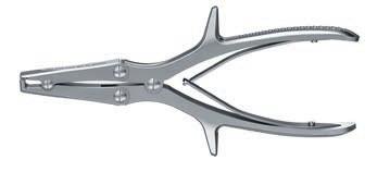
4 Cerclage Passer. For minimally invasive application of cerclage cables. Overview Cerclage Passer Techniques for the treatment of periprosthetic fractures and other indications often include the application of cerclage cables. The Cerclage Passer Instrument Set contains the additional instruments needed for minimally invasive procedures. Modular set configuration The cerclage passer can be used for the minimal invasive application of cerclage cables. The modular case concept allows storage of the relevant instruments on modular instrument trays. Note: Set does not include implants Available in two sizes (diameter 46 mm and 60 mm) adapted to anatomy. Allow passage of cable around the bone through small approach. One size trocar is compatible with both cerclage passer sizes. Designed as two separate halves to facilitate sequential insertion through one incision. Quick Step Surgical Technique 2 DePuy Synthes Cerclage Passer Surgical Technique

5 Cerclage Tunneling Device Prepares the way and facilitates the passage of the cerclage passer. Available in two sizes that correspond with the bending diameter of the cerclage passer. Cerclage Passer Surgical Technique DePuy Synthes 3
6 Indications For general orthopedic trauma surgery involving the application of cerclage cables Periprosthetic fractures of the femur Subtrochanteric fractures Hip and knee prostheses Additional fixation Temporary reduction 4 DePuy Synthes Cerclage Passer Surgical Technique


7 Clinical Cases 78 year old female with AO 32-A1.1 fracture Preoperative Postoperative 72 year old female with AO 32-A1.2 fracture Preoperative Postoperative Cerclage Passer Surgical Technique DePuy Synthes 5
 technique requires a keen understanding of the neurovascular anatomy.")
8 Preparation 1 Preparation Set Instrument Set for minimally invasive Cable Cerclage Optional set Cable System in Vario Case Implants x98.80x.01 Cerclage Cables with Crimp Precaution: Application of cerclage cables using a minimally invasive (MIS) technique requires a keen understanding of the neurovascular anatomy. Complete a preoperative radiographic assessment and prepare the preoperative plan. Position the patient according to the respective fracture requirements on a radiolucent operating table. Complete the closed reduction with traction to minimize anatomic distortion. 2 Incision and preparation of soft tissue tunnel Instruments Cerclage Tunneling Device, B 46 mm Cerclage Tunneling Device, B 60 mm Choose the appropriate size cerclage tunneling device for the field of application and the fracture. Make an incision and carefully insert the tunneling device over the periosteum from ventral and dorsal around the bone. Make an incision in the skin and fascia approximately 4 5 cm wide to avoid tension. Ensure the cerclage tunneling device perforates the fascia directly adjacent to the linea aspera on the dorsal femur. Preparation of the tunnel is necessary to facilitate the following insertion of the cerclage passer. 6 DePuy Synthes Cerclage Passer Surgical Technique
9 Surgical Steps 1 Insertion of cerclage passer Instruments Cerclage Passer, B 46 mm, minimally invasive Cerclage Passer, B 60 mm, minimally invasive Trocar, for Cerclage Passer Nos and Put one trocar in each tube of the cerclage passer. This prevents soft tissue from entering the cannulated tubes of the cerclage passer. The posterior and anterior cerclage passer handles should be passed through the soft-tissue tunnel created by the cerclage tunneling device. Keep contact with the bone all the time. Precaution: To prevent damage do not apply too much force while inserting the cerclage passer. Deformation of the tubes can result in non-closure of the instrument when connecting the halves. Place the cerclage passer handles directly adjacent to the bone surface to connect the two handle halves. Where possible, use the smaller cerclage passer. Make sure the instrument is close to the bone. Precaution: When the cerclage passer is in use, pay attention to the sterile field. Cerclage Passer Surgical Technique DePuy Synthes 7
. Precaution: While connecting the two parts, the tips must not meet.")
 can be used for orientation.")
10 Surgical Steps 2 Connection and closure of cerclage passer 1 To connect the two parts of the cerclage passer, slide the notch of one half into the corresponding part of the other half (1, 2). Precaution: While connecting the two parts, the tips must not meet. Do not attempt to close the forceps as long as the middle of the forceps is not connected properly. The markings on each half ( small, large ) can be used for orientation. When the forceps are connected together, the markings will appear in the same direction. 2 8 DePuy Synthes Cerclage Passer Surgical Technique
. Remove the trocars.")

11 Once the two connecting parts have been brought together, close the forceps until the markings on the two halves are aligned and form a line (3). The tips of the cannulated tubes will then meet and form a passageway for the cable. 3 Secure the closed cerclage passer by locking the bracket (4). Remove the trocars. 4 Note: Open and close the bracket by pressing the ends of the handles slightly together. Closed correctly, the bars of the cerclage passer forceps are parallel. The correctly closed position of the cerclage passer can be controlled by moving it up and down or using image intensifier control. Warning: When closing the cerclage passer, be careful not to damage any soft-tissue structures. Where necessary, enlarge the approach to verify that no soft-tissue structures (mainly the neurovascular structures) are being damaged. Never push the handles medial to bring the halves together; instead, pull them towards the medial cortex. The clamping should be performed without force. Cerclage Passer Surgical Technique DePuy Synthes 9

12 Surgical Steps 3 Insertion of cable passing tube Instrument S Cable Passing Tube, length 400 mm, sterile Push the cable passing tube through the tube of the closed cerclage passer. The only correct direction for insertion is marked by an arrow. Note: It is not possible to pass a pre-assembled cerclage cable without cable passing tube. The crimp at the beaded end of the cable allows no direct passage through the cerclage passer. The cable passing tube is for single use only and must not be reprocessed or resterilized. Precaution: Do not use pliers for cable passing tube insertion due to tube damages. The cable passing tube must exit the opposite part of the cerclage passer. Do not open the cerclage passer when the cable passing tube is in use. The ends of the cerclage passer might cut the cable passing tube. Note: For better insertion bevel the cable passing tube. 11 DePuy Synthes Cerclage Passer Surgical Technique
13 4 Remove cerclage passer forceps Unlock the forceps by opening the bracket. Disconnect the two halves of the cerclage passer forceps and remove the half with arrow. Be sure that the inserted cable passing tube stays around the bone. Hold the opposite end of the cable passing tube by hand. Cerclage Passer Surgical Technique DePuy Synthes 11
14 Surgical Steps 5 Insert cable through cable passing tube Implants Cerclage Cable with Crimp B 1.0 mm, Stainless Steel Cerclage Cable with Crimp B 1.7 mm, Stainless Steel Cerclage Cable with Crimp B 1.0 mm, Titanium Alloy (TAN) Cable with Crimp B 1.7 mm, Titanium Alloy (TAN) Select the cable according to the application and fracture. Push the end without bead through the cable passing tube without the cerclage passer until the cable exits. Remove the other half of the cerclage passer. Precaution: If the cerclage cable is used in contact with other implants (e.g. LCP broad curved plate), consider the correct combination of metals. 11 DePuy Synthes Cerclage Passer Surgical Technique

15 6 Remove cable passing tube Remove the cable passing tube by pulling it over the end without bead. Take care that the inserted cable stays around the bone. Cerclage Passer Surgical Technique DePuy Synthes 11
16 Surgical Steps 7 Tightening and fixation of cable For further procedure, please refer to the Cable System technique guide ( ) page 8, step 4A. 8 Cut cable Instrument Front Cutter Cut the loose end of the cable using the front cutter. Position the cutting jaws very close to the crimp, and make the cut in one action to produce a clean cut. Ensure that the adjacent cerclage cables do not get damaged. 11 DePuy Synthes Cerclage Passer Surgical Technique
17 Implants Cerclage Cable with Crimp B 1.0 mm, Stainless Steel Cerclage Cable with Crimp B 1.7 mm, Stainless Steel Cerclage Cable with Crimp B 1.0 mm, Titanium Alloy (TAN) Cable with Crimp B 1.7 mm, Titanium Alloy (TAN) For additional implants please refer to the Cable System technique guide ( ), page 32. Cerclage Passer Surgical Technique DePuy Synthes 11

18 Instruments Cerclage Passer B 46 mm, minimally invasive Cerclage Passer B 60 mm, minimally invasive Trocar, for Cerclage Passer Nos and Cerclage Tunneling Device B 46 mm Cerclage Tunneling Device B 60 mm Front Cutter Cable Tensioner S Cable Passing Tube, length 400 mm, sterile 16 DePuy Synthes Cerclage Passer Surgical Technique


19 Cable Crimper Attachment Bit for Tension Holder Tension Holder, for temporary use Cerclage Passer Surgical Technique DePuy Synthes 11


20 Sets Instrument Set for minimally invasive Cable Cerclage Tray for Standard Instruments for minimally invasive Wire and Cable Cerclage Cerclage Tunneling Device B 46 mm Cerclage Passer B 46 mm, minimally invasive Cerclage Tunneling Device B 60 mm Cerclage Passer B 60 mm, minimally invasive Trocar, for Cerclage Passer Nos and Tray for Additional Instruments for minimally invasive Cable Cerclage Cable Tensioner Cable Crimper Attachment Bit for Tension Holder Tension Holder, for temporary use Front Cutter S Cable Passing Tube, length 400 mm, sterile 11 DePuy Synthes Cerclage Passer Surgical Technique
21 Additionally available in sterile S Cable Passing Tube, length 400 mm, sterile Additionally available Labelling Plate for Instrument Set for minimally invasive Cerclage, for Vario Case Lid for Modular Tray, size 1/ Cleaning Brush, for Compact Air Drive, Power Drive and Colibri Vario Case components Lid (Stainless Steel), size 1/1, for Vario Case Vario Case, Framing, size 1/1, height 126 mm Cerclage Passer Surgical Technique DePuy Synthes 11
22 Bibliography Schmidt AH, Kyle RF (2002) Periprosthetic fractures of the femur. Orthop Clin North Am: Tong G, Bavonratanavech S (2006) Minimally Invasive Plate Osteosynthesis (MIPO): Concepts and cases presented by the AO East Asia 22 DePuy Synthes Cerclage Passer Surgical Technique
23 MRI Information Torque, Displacement and Image Artifacts according to ASTM F , ASTM F e1 and ASTM F Non-clinical testing of worst case scenario in a 3 T MRI system did not reveal any relevant torque or displacement of the construct for an experimentally measured local spatial gradient of the magnetic field of 3.69 T/m. The largest image artifact extended approximately 169 mm from the construct when scanned using the Gradient Echo (GE). Testing was conducted on a 3 T MRI system. Radio-Frequency-(RF-)induced heating according to ASTM F a Non-clinical electromagnetic and thermal testing of worst case scenario lead to peak temperature rise of 9.5 C with an average temperature rise of 6.6 C (1.5 T) and a peak temperature rise of 5.9 C (3 T) under MRI Conditions using RF Coils [whole body averaged specific absorption rate (SAR) of 2 W/kg for 6 minutes (1.5 T) and for 15 minutes (3 T)]. Precautions: The above mentioned test relies on non-clinical testing. The actual temperature rise in the patient will depend on a variety of factors beyond the SAR and time of RF application. Thus, it is recommended to pay particular attention to the following points: It is recommended to thoroughly monitor patients undergoing MR scanning for perceived temperature and/or pain sensations. Patients with impaired thermo regulation or temperature sensation should be excluded from MR scanning procedures. Generally it is recommended to use a MR system with low field strength in the presence of conductive implants. The employed specific absorption rate (SAR) should be reduced as far as possible. Using the ventilation system may further contribute to reduce temperature increase in the body. Cerclage Passer Surgical Technique DePuy Synthes 22
24
25
26
27
28 DSEM/TRM/0815/ /15 Synthes GmbH Eimattstrasse Oberdorf Switzerland Tel: Fax: This publication is not intended for distribution in the USA. All surgical techniques are available as PDF files at DePuy Synthes Trauma, a division of Synthes GmbH All rights reserved
For Minimally Invasive Application of Cerclage Wires. Cerclage Passer. Surgical Technique
 For Minimally Invasive Application of Cerclage Wires Cerclage Passer Surgical Technique Table of Contents Introduction Cerclage Passer 2 Surgical Technique Preparation 4 Insert Cerclage Passer 5 Connect
HCS 1.5. The countersinkable compression screw.
 HCS 1.5. The countersinkable compression screw. Surgical Technique This publication is not intended for distribution in the USA. Instruments and implants approved by the AO Foundation. Table of Contents
LCP Pilon Plate 2.7/3.5
 LCP Pilon Plate 2.7/3.5 Surgical Technique This publication is not intended for distribution in the USA. Instruments and implants approved by the AO Foundation. Table of contents Indications 2 Implants
Variable Angle LCP Mesh Plate 2.4/2.7. Part of the Variable Angle LCP Forefoot/Midfoot System 2.4/2.7.
 Variable Angle LCP Mesh Plate 2.4/2.7. Part of the Variable Angle LCP Forefoot/Midfoot System 2.4/2.7. Surgical Technique This publication is not intended for distribution in the USA. Instruments and implants
Variable Angle LCP Tarsal Plates 2.4/2.7. Navicular Plate and Cuboid Plates.
 Variable Angle LCP Tarsal Plates 2.4/2.7. Navicular Plate and Cuboid Plates. Surgical Technique This publication is not intended for distribution in the USA. Instruments and implants approved by the AO
Cable System. For Orthopaedic Trauma Surgery.
 Cable System. For Orthopaedic Trauma Surgery. Surgical Technique This publication is not intended for distribution in the USA. Instruments and implants approved by the AO Foundation. Image intensifier
LCP Pilon Plate 2.7/3.5. Surgical Technique
 LCP Pilon Plate 2.7/3.5 Surgical Technique Image intensifier control This description alone does not provide sufficient background for direct use of DePuy Synthes products. Instruction by a surgeon experienced
2.4 mm Cannulated Screw. An integral part of the Synthes Cannulated Screw System (CSS).
.") 2.4 mm Cannulated Screw. An integral part of the Synthes Cannulated Screw System (CSS). Surgical Technique This publication is not intended f distribution in the USA. and implants approved by the AO Foundation.
2.4 mm Cannulated Screw. An integral part of the Synthes Cannulated Screw System (CSS). Surgical Technique This publication is not intended f distribution in the USA. and implants approved by the AO Foundation.
VECTRA SURGICAL TECHNIQUE. Anterior cervical plate system. This publication is not intended for distribution in the USA.
 VECTRA Anterior cervical plate system This publication is not intended for distribution in the USA. SURGICAL TECHNIQUE Image intensifier control This description alone does not provide sufficient background
Cannulated Percutaneous Guiding System. For percutaneous placement of 3.5 mm pelvic and cortex screws in the pelvic area.
 Cannulated Percutaneous Guiding System. For percutaneous placement of 3.5 mm pelvic and cortex screws in the pelvic area. Technique Guide This publication is not intended for distribution in the USA. Instruments
Instruments for removing Synthes screws. Screw Extraction Set. Handling Technique
 Instruments for removing Synthes screws Screw Extraction Set Handling Technique Image intensifier control This description alone does not provide sufficient background for direct use of DePuy Synthes products.
Synthes Kirschner Wires and Cerclage Wires. Multifunctional devices for temporary fixation, tension band, cerclage wiring and percutaneous pinning.
 Technique Guide Synthes Kirschner Wires and Cerclage Wires. Multifunctional devices for temporary fixation, tension band, cerclage wiring and percutaneous pinning. Image intensifier control Warning This
Technique Guide. Cable System. For Orthopaedic Trauma Surgery.
 Technique Guide Cable System. For Orthopaedic Trauma Surgery. Table of Contents Introduction Overview 2 AO Principles 4 Indications and Contraindications 5 Surgical Technique Standard Cerclage Technique
VECTRA. SURGICAL TECHNIQUE. Anterior cervical plate system. This publication is not intended for distribution in the USA.
 VECTRA. Anterior cervical plate system. This publication is not intended for distribution in the USA. SURGICAL TECHNIQUE Contents Indications and contraindications Implants Vario Case Instruments Surgical
Technique Guide. 2.4/2.7 mm Locking Tarsal Plates. Talus Plate, Navicular Plate and Cuboid Plate.
 Technique Guide 2.4/2.7 mm Locking Tarsal Plates. Talus Plate, Navicular Plate and Cuboid Plate. Table of Contents Introduction 2.4/2.7 mm Locking Tarsal Plates 2 AO Principles 4 Indications 5 Clinical
Technique Guide. Modular Sternal Cable System. Flexibility and strength in sternal closure and repair.
 Technique Guide Modular Sternal Cable System. Flexibility and strength in sternal closure and repair. Table of Contents Introduction Overview 2 Indications and Contraindications 3 Surgical Technique A.
HCS 2.4/3.0. The countersinkable compression screw.
 Technique Guide HCS 2.4/3.0. The countersinkable compression screw. Table of Contents Introduction Features and Benefits 2 Functional Principle 3 Indications 4 Surgical Technique Hand Scaphoid 5 Foot
DLS Dynamic Locking Screw. Combined with LCP Locking Compression Plate.
 DLS Dynamic Locking Screw. Combined with LCP Locking Compression Plate. Instructions for Use Discontinued June 2016 DSEM/TRM/0517/0844(1) Table of Contents Introduction DLS Dynamic Locking Screw 2 Indications
Technique Guide. Occipito-Cervical Fusion System. Implants and instruments designed to optimize fixation to the occiput.
 Technique Guide Occipito-Cervical Fusion System. Implants and instruments designed to optimize fixation to the occiput. Table of Contents Introduction Overview 2 AO ASIF Principles 4 Indications and Contraindications
Technique Guide. Quadrilateral Surface Plates 3.5. Part of the Low Profile Pelvic System 3.5.
 Technique Guide Quadrilateral Surface Plates 3.5. Part of the Low Profile Pelvic System 3.5. Table of Contents Introduction Quadrilateral Surface Plates 3.5 2 AO Principles 4 Indications 5 Surgical Technique
Instructions for Use. LCP Locking Compression Plate. Combine without Compromise.
 Instructions for Use LCP Locking Compression Plate. Combine without Compromise. Table of Contents LCP: Combine without Compromise 2 AO ASIF Principles of Osteosynthesis 4 Indications and Contraindications
90 SCREWDRIVER Minimally invasive drilling and screw insertion
 90 SCREWDRIVER Minimally invasive drilling and screw insertion This publication is not intended for distribution in the USA. SURGICAL TECHNIQUE This description alone does not provide sufficient background
Technique Guide. Modular Sternal Cable System. Flexibility and strength in sternal closure and repair.
 Technique Guide Modular Sternal Cable System. Flexibility and strength in sternal closure and repair. Table of Contents Introduction Modular Sternal Cable System 2 Indications 4 Modular Sternal Closure
Occipito-Cervical Fusion System
 Implants and Instruments designed to enhance Fixation to the Occiput Occipito-Cervical Fusion System Surgical Technique Image intensifier control This description alone does not provide sufficient background
Technique Guide. 4.5 mm Cannulated Screws. Part of the Synthes Cannulated Screw System.
 Technique Guide 4.5 mm Cannulated Screws. Part of the Synthes Cannulated Screw System. TableofContents Introduction 4.5 mm Cannulated Screws 2 AO Principles 3 Indications 4 Surgical Technique Surgical
URS Degen. Top loading pedicle screw system for posterior stabilization.
 URS Degen. Top loading pedicle screw system for posterior stabilization. Technique Guide This publication is not intended for distribution in the USA. Table of Contents Introduction URS Degen 2 AO Principles
Variable Angle LCP Forefoot/Midfoot System 2.4/2.7. Procedure specific plates for osteotomies, arthrodeses and fractures of the foot.
 Instruction for Use Variable Angle LCP Forefoot/Midfoot System 2.4/2.7. Procedure specific plates for osteotomies, arthrodeses and fractures of the foot. Table of Contents Introduction VA-LCP Forefoot/Midfoot
OPERATIVE TECHNIQUE RIVAL REDUCE FRACTURE PLATING SYSTEM. foot & ankle trauma procedures
 OPERATIVE TECHNIQUE RIVAL REDUCE FRACTURE PLATING SYSTEM foot & ankle trauma procedures INTRODUCTION 3 SYSTEM DESCRIPTION 3 TECHNICAL DETAILS 4 SALES AND MARKETING CONFIGURATION 5 OPERATIVE TECHNIQUE 7
6.5 mm and 7.3 mm Cannulated Screws Technique Guide
 6.5 mm and 7.3 mm Cannulated Screws Technique Guide An Integral Part of the SYNTHES Cannulated Screw System Original Instruments and Implants of the Association for the Study of Internal Fixation AO ASIF
Instruments for Removing DePuy Synthes Screws. Screw Removal Set
 Instruments for Removing DePuy Synthes Screws Screw Removal Set Surgical Technique Table of Contents Introduction Screw Removal Set 2 Surgical Technique Preoperative Planning and Preparation 6 Removal
MATRIX COMBO PLATING SYSTEM. Streamlined set for craniofacial and mandibular trauma and reconstruction
 MATRIX COMBO PLATING SYSTEM Streamlined set for craniofacial and mandibular trauma and reconstruction MATRIXCOMBO PLATING SET MATRIXCOMBO PLATING SET (01.503.400) The aim of surgical fracture treatment
The Percutaneous Reduction Forceps Technique Guide
 The Percutaneous Reduction Forceps Technique Guide Indications + Product Overview Introduction The Percutaneous Reduction Forceps The Percutaneous Reduction Forceps facilitate standard technique for fixation
Occipito-Cervical Fusion System. Implants and instruments designed to optimize fixation to the occiput.
 Occipito-Cervical Fusion System. Implants and instruments designed to optimize fixation to the occiput. Technique Guide This publication is not intended for distribution in the USA. Instruments and implants
Technique Guide. Variable Angle LCP Opening Wedge Plates 2.4/2.7. Part of the Variable Angle LCP Forefoot / Midfoot System 2.4 / 2.7.
 Technique Guide Variable Angle LCP Opening Wedge Plates 2.4/2.7. Part of the Variable Angle LCP Forefoot / Midfoot System 2.4 / 2.7. Table of Contents Introduction Variable Angle LCP Opening Wedge Plates
OCCIPITO-CERVICAL FUSION SYSTEM Implants and instruments designed to optimize fixation to the occiput
 OCCIPITO-CERVICAL FUSION SYSTEM Implants and instruments designed to optimize fixation to the occiput Instruments and implants approved by the AO Foundation. This publication is not intended for distribution
1.5 MM LCP SYSTEM. For treatment of fractures and arthrodeses of canines and felines SURGICAL TECHNIQUE
 1.5 MM LCP SYSTEM For treatment of fractures and arthrodeses of canines and felines SURGICAL TECHNIQUE TABLE OF CONTENTS INTRODUCTION 1.5 mm LCP System 2 AO Principles 4 SURGICAL TECHNIQUE Reduce Fracture
Technique Guide. 7.0 mm Cannulated Screws. Part of the Synthes Cannulated Screw System.
 Technique Guide 7.0 mm Cannulated Screws. Part of the Synthes Cannulated Screw System. Table of Contents Introduction 7.0 mm Cannulated Screws 2 AO Principles 3 Indications 4 Surgical Technique Surgical
The information contained in this document is intended for healthcare professionals only.
 The information contained in this document is intended for healthcare professionals only. Apex Pin Fixation System Half Pins, Transfixing Pins & Instruments 1 Table of Contents Introduction.......................................................................01
Universal Humeral Nail
 990210009 INDEX Indications Preoperative Planning Patient Position Surgical Technique - Step 1 Open Humerus - Step 2 Calibrate The Nail - Step 3 Insert Nail - Step 4 Proximal Locking - Step 5 Assemble
7.0 mm Cannulated Screws
 Part of the DePuy Synthes Cannulated Screw System 7.0 mm Cannulated Screws Surgical Technique Table of Contents Introduction 7.0 mm Cannulated Screws 2 AO Principles 3 Indications 4 Surgical Technique
Apex & HA Apex Pins. Pin Fixation System. Half Pins, Transfixing Pins HA Coated Half Pins for long term fixation Instruments
 Apex & HA Apex Pins Pin Fixation System Half Pins, Transfixing Pins HA Coated Half Pins for long term fixation Instruments Apex Pins This publication sets forth detailed recommended procedures for using
3.5 mm and 4.5 mm Curved Locking Compression Plates (LCP )
") For Minimally Invasive Osteosynthesis 3.5 mm and 4.5 mm Curved Locking Compression Plates (LCP ) Surgical Technique Table of Contents Introduction 3.5 mm and 4.5 mm Curved Locking Compression 2 Plates
For Minimally Invasive Osteosynthesis 3.5 mm and 4.5 mm Curved Locking Compression Plates (LCP ) Surgical Technique Table of Contents Introduction 3.5 mm and 4.5 mm Curved Locking Compression 2 Plates
Technique Guide. LCP Pilon Plate 2.7/3.5
 Technique Guide LCP Pilon Plate 2.7/3.5 LCP Pilon Plate 2.7/3.5 Table of contents Indications 3 Implants 4 Instruments 5 Surgical technique 6 Implant removal 12 Image intensifier control Warning This
3.5 MM low-profile cortex screws
 3.5 MM low-profile cortex screws Low-profle fxation option compatible with all Trauma 3.5 mm plates MechanicallY comparable To DEPUY SYNTHES TRAUMA standard 3.5 MM cortex screws low-profile option To MiniMiZe
Part of the DePuy Synthes Cannulated Screw System. 3.5 mm Cannulated Screws
 Part of the DePuy Synthes Cannulated Screw System 3.5 mm Cannulated Screws Surgical Technique Table of Contents Introduction 3.5 mm Cannulated Screws 2 AO Principles 3 Indications 4 Surgical Technique
SYNAPSE SYSTEM An enhanced set of implants and instruments for posterior stabilization of the cervical and upper thoracic spine
 SYNAPSE SYSTEM An enhanced set of implants and instruments for posterior stabilization of the cervical and upper thoracic spine Instruments and implants approved by the AO Foundation. This publication
Technique Guide. Synapse System. An enhanced set of instruments and implants for posterior stabilization of the cervical and upper thoracic spine.
 Technique Guide Synapse System. An enhanced set of instruments and implants for posterior stabilization of the cervical and upper thoracic spine. Table of Contents Introduction Synapse System 2 AO Principles
Small Fragment Locking Compression Plate (LCP ) System Stainless Steel and Titanium TECHNIQUE GUIDE
 System Stainless Steel and Titanium TECHNIQUE GUIDE") Small Fragment Locking Compression Plate (LCP ) System Stainless Steel and Titanium TECHNIQUE GUIDE R Original Instruments and Implants of the Association for the Study of Internal Fixation AO ASIF Introduction
Small Fragment Locking Compression Plate (LCP ) System Stainless Steel and Titanium TECHNIQUE GUIDE R Original Instruments and Implants of the Association for the Study of Internal Fixation AO ASIF Introduction
OsteoBridge IKA Intramedullary Knee Arthrodesis Fixation System. From the «BioBall Company» OsteoBridge Family
 From the «BioBall Company» OsteoBridge Family OsteoBridge IKA Intramedullary Knee Arthrodesis Fixation System The modular system for the fixation of the knee joint 01. OsteoBridge IKA The OsteoBridge IKA
VARIABLE ANGLE LOCKING HAND SYSTEM
 VARIABLE ANGLE LOCKING HAND SYSTEM For fragment-specific fracture fixation with variable angle locking and locking technology Instruments and implants approved by the AO Foundation. This publication is
3.5 mm Cannulated Screw Technique Guide
 3.5 mm Cannulated Screw Technique Guide An Integral Part of the SYNTHES Cannulated Screw System Original Instruments and Implants of the Association for the Study of Internal Fixation AO ASIF The 3.5 mm
Integra. Stainless Headed Compression Screw System SURGICAL TECHNIQUE
 Integra Stainless Headed Compression Screw System SURGICAL TECHNIQUE Table of Contents Design Rationale...2 Indications...2 Contraindications...2 Surgical Technique Step 1: Inserting Guide Wire... 3 Step
Technique Guide. Variable Angle LCP 1 st MTP Fusion Plates 2.4/2.7. Part of the Variable Angle LCP Forefoot / Midfoot System 2.4 / 2.7.
 Technique Guide Variable Angle LCP 1 st MTP Fusion Plates 2.4/2.7. Part of the Variable Angle LCP Forefoot / Midfoot System 2.4 / 2.7. Table of Contents Introduction Variable Angle LCP 1 st MTP Fusion
DISTAL RADIUS PLATES 3.5 mm / ANGULARLY STABLE. Distal radius plates 3,5 mm / angularly stable. Locking bone screws. Cortical bone screw
 SURGICAL NÁSTROJE TECHNIQUE PRO ARTROSKOPII DISTAL INSTRUMENTS RADIUS PLATES FOR ARTHROSCOPY 3.5 mm / ANGULARLY STABLE Distal radius plates 3.5 mm / angularly stable Indication The plates are used for
Integra. Capture Screw System SURGICAL TECHNIQUE
 Integra Capture Screw System SURGICAL TECHNIQUE Table of Contents Indications... 2 Contraindications... 2 System Description... 2 System Features... 2 Cannulated Low-Profile Screws (AC-Series) Overview...
Technique Guide Supplement. Standard DHS Lag Screw with LCP DHHS Sideplate.
 Technique Guide Supplement Standard DHS Lag Screw with LCP DHHS Sideplate. Table of Contents Surgical Technique Standard DHS Lag Screw with LCP DHHS 2 Sideplate Technique DHS One-step Lag Screw with DHHS
ACLP Anterior Cervical Locking Plate System TECHNIQUE GUIDE
 ACLP Anterior Cervical Locking Plate System TECHNIQUE GUIDE Instruments and implants approved by the AO Foundation ACLP Anterior Cervical Locking Plate System The ACLP System is designed to reduce the
Zimmer Natural Nail System
 Zimmer Natural Nail System Cephalomedullary Nail Surgical Technique Compact Case- Short Nails Only SMALL Zimmer Natural Nail System Cephalomedullary Nail Technique - Small 1 Zimmer Natural Nail System
SynReam. The Synthes reaming system
 SynReam. The Synthes reaming system Surgical Technique This publication is not intended for distribution in the USA. Instruments and implants approved by the AO Foundation. Image intensifier control This
Zimmer Natural Nail System
 Zimmer Natural Nail System Cephalomedullary Nail Surgical Technique Compact Case - Short Nails Only STANDARD Zimmer Natural Nail System Cephalomedullary Nail Surgical Technique - Standard 1 Zimmer Natural
Top Loading Pedicle Screw and Hook System for Posterior Stabilization. URS System. Surgical Technique
 Top Loading Pedicle Screw and Hook System for Posterior Stabilization URS System Surgical Technique Image intensifier control This description alone does not provide sufficient background for direct use
Reflex TM Surgical Technique. Anterior Cervical Plate
 Reflex TM Surgical Technique Anterior Cervical Plate Surgical Technique Acknowledgement: Stryker Spine extends their thanks to the following surgeons for their participation in the development of the Reflex
Lag Screw Device TECHNIQUE GUIDE. Indicated for symphyseal fracture fixation of the mandible. Instruments and implants approved by the AO Foundation
 Lag Screw Device TECHNIQUE GUIDE Indicated for symphyseal fracture fixation of the mandible Instruments and implants approved by the AO Foundation Lag Screw Device Indicated for symphyseal fracture fixation
2.4 mm and 3.0 mm Headless Compression Screws
 For Fixation of Small Bones and Small Bone Fragments 2.4 mm and 3.0 mm Headless s Surgical Technique Table of Contents Introduction 2.4 mm and 3.0 mm Headless 2 Technique Overview 4 AO Principles 5 Indications
OPERATIVE TECHNIQUE RIVAL BITE HEADED CANNULATED AND HEADLESS COMPRESSION SCREWS. foot & ankle applications
 OPERATIVE TECHNIQUE RIVAL BITE HEADED CANNULATED AND HEADLESS COMPRESSION SCREWS foot & ankle applications INTRODUCTION 3 SYSTEM DESCRIPTION 3 TECHNICAL DETAILS 4 SALES AND MARKETING CONFIGURATION 6 OPERATIVE
Vortex TRAUMATOLOGY. Vortex Distal Femur
 Vortex TRAUMATOLOGY Vortex Distal Femur 1 Content 1. Introduction 4 4. Implant list 16-17 The following surgical description contains general outlines for Vortex Distal Femur plating. However, the operating
SpeedTip CCS 5.0, 7.0
 SURGICAL TECHNIQUE STEP BY STEP SpeedTip CCS 5.0, 7.0 Cannulated Compression Screws APTUS 2 SpeedTip CCS 5.0, 7.0 Cannulated Compression Screws Contents 3 Introduction Product Materials Indications Contraindications
Zimmer Natural Nail System. Cephalomedullary Nail Surgical Technique SMALL
 Zimmer Natural Nail System Cephalomedullary Nail Surgical Technique SMALL Zimmer Natural Nail System Cephalomedullary Nail Technique - Small 1 Zimmer Natural Nail System Cephalomedullary Nail Surgical
Omega 3 System Compression Hip Screw
 Omega 3 System Compression Hip Screw Hip Fracture Axially Stable Locking Option Contents Omega3 Compression Hip Screw Introduction 4 Potential Features & Benefits 5 Relative Indications & Contraindications
The Titanium Cannulated Lateral Entry Femoral Recon Nail. Expert nailing system with radiolucent instrumentation.
 The Titanium Cannulated Lateral Entry Femoral Recon Nail. Expert nailing system with radiolucent instrumentation. Technique Guide EXPERT Nailing System Table of Contents Introduction Titanium Cannulated
SpeedTip CCS 5.0, 7.0
 SURGICAL TECHNIQUE STEP BY STEP SpeedTip CCS 5.0, 7.0 Cannulated Compression Screws APTUS 2 SpeedTip CCS 5.0, 7.0 Cannulated Compression Screws SpeedTip CCS 5.0, 7.0 Cannulated Compression Screw 3 SpeedTip
VARIABLE ANGLE LOCKING HAND SYSTEM
 VARIABLE ANGLE LOCKING HAND SYSTEM For fragment-specific fracture fixation with variable angle locking and locking technology SURGICAL TECHNIQUE TABLE OF CONTENTS INTRODUCTION Variable Angle Locking Hand
LCP Pilon Plate 2.7/3.5
 Surgical Technique LCP Locking Compression Plate Original Instruments and Implants of the Association for the Study of Internal Fixation AO/ASIF Table of contents Indications 3 Implants 4 Instruments 5
MatrixMANDIBLE. Mandible Plating System.
 MatrixMANDIBLE. Mandible Plating System. Surgical Technique EXPERT CMF Nailing Matrix System This publication is not intended for distribution in the USA. Instruments and implants approved by the AO Foundation.
Distal Volar Radius Plate Procedure Steps.
 Distal Volar Radius Plate Procedure Steps www.carbo-fix.com Introduction The CarboFix Implants The CarboFix Distal Volar Radius Plates are made of numerous continues carbon fibers embedded in polymer (PEEK).
OPERATIVE TECHNIQUE RIVAL VIEW PLATING SYSTEM. foot & ankle reconstruction procedures
 OPERATIVE TECHNIQUE RIVAL VIEW PLATING SYSTEM foot & ankle reconstruction procedures INTRODUCTION 3 SYSTEM DESCRIPTION 3 TECHNICAL DETAILS 4 SALES AND MARKETING CONFIGURATION 5 OPERATIVE TECHNIQUE 7 OPERATIVE
Biomet Peritrochanteric Nail (PTN) System. Surgical Technique
 System. Surgical Technique") Biomet Peritrochanteric Nail (PTN) System Surgical Technique Contents Introduction... Page 1 Indications... Page 2 OTA Femoral Fracture Classifications... Page 3 Surgical Technique... Page 4 Patient Positioning...
Biomet Peritrochanteric Nail (PTN) System Surgical Technique Contents Introduction... Page 1 Indications... Page 2 OTA Femoral Fracture Classifications... Page 3 Surgical Technique... Page 4 Patient Positioning...
CMF Surgery. Angulus2. Angled Screwdriver. ref
 CMF Surgery Angulus2 Angled Screwdriver ref. 90-126-02-04 It s the head that counts and the face. There is nothing with which we identify ourselves more than with the face. We are how we see ourselves.
64 SECUROS Orthopedic Resource Guide 1 (877) BONEFIX ( )
 BONEFIX ( )") 64 SECUROS Orthopedic Resource Guide 1 (877) BONEFIX (266-3349) www.securos.com SECUROS PINS WIRES TOOLS Pin & Wire Management Introduction...66 Starter Kits...66 Pins -Steinmann/Intermedullary...67 -Self
64 SECUROS Orthopedic Resource Guide 1 (877) BONEFIX (266-3349) www.securos.com SECUROS PINS WIRES TOOLS Pin & Wire Management Introduction...66 Starter Kits...66 Pins -Steinmann/Intermedullary...67 -Self
MatrixMANDIBLE Preformed Reconstruction Plates. Preshaped to the mandibular anatomy.
 MatrixMANDIBLE Preformed Reconstruction Plates. Preshaped to the mandibular anatomy. Technique Guide CMF Matrix Table of Contents Introduction MatrixMANDIBLE Preformed Reconstruction Plates 2 AO Principles
2.0. Contents Function control
 Contents 2.0 Drill bits 2.1 Medullary reamer heads 2.2 Burrs 2.3 Bone taps 2.4 Drill sleeves with serrated ends 2.5 Drill guides for plates 2.6 Aiming device 2.7 Pointed drill guide 2.8 Quick coupling
The CentroNail System: Universal Femoral Nailing Applications
 O P E R A T I V E T E C H N I Q U E The CentroNail System: Universal Femoral Nailing Applications 1 2 3 FEATURES AND BENEFITS Proximal locking Locking screws 4 INDICATIONS 5 EQUIPMENT REQUIRED 9 17 26
Distal Medial Tibia Plate Surgical Technique
 Locking Compression Technology by aap 1 Disclaimer This surgical technique is exclusively intended for medical professionals, especially physicians, and therefore may not be regarded as a source of information
S U R G I C A L T E C H N I Q U E TRAUMA & EXTREMITIES GROUP
 S U R G I C A L T E C H N I Q U E TRAUMA & EXTREMITIES GROUP TABLE OF CONTENTS ATN NAIL SYSTEM DESIGN RATIONALE INDICATIONS/CONTRAINDICATIONS PREOPERATIVE PLANNING AND PATIENT POSITIONING NAIL INSERTION
VLP FOOT Variable Angle Locked Plating System
 Surgical Technique VLP FOOT Variable Angle Locked Plating System Surgical Technique Table of Contents Product overview Implant selection...2 Introduction...3 System overview...4 Indications...4 Design
Orthopedic Bone Nail System Universal Humeral Nail
 Orthopedic Bone Nail System Universal Humeral Nail Surgical Technique Manual Note: The surgical procedures should be performed under the guidance of qualified skilled orthopedic surgeons, and this surgical
Peanut Growth Control Plating System. Surgical Technique
 Peanut Growth Control Plating System Surgical Technique 1 Peanut Growth Control Plating System Table of Contents System Design Features... 2 Instrument Tray... 5 Implant Caddy... 6 Surgical Technique...
MIS TECHNOLOGY GUIDE READ PRODUCT INSERT THOROUGHLY BEFORE USE
 COR-KNOT FIG. 1 MIS TECHNOLOGY GUIDE READ PRODUCT INSERT THOROUGHLY BEFORE USE 1 3 COR-KNOT QUICK LOAD UNIT DESCRIPTION Each COR-KNOT QUICK LOAD UNIT provides one sterile COR-KNOT FASTENER 1 held in a
VariAx Fibula Locking Plate System
 VariAx Fibula Locking Plate System Operative Technique Distal Fibula Fracture Repair Polyaxial Locking Technology Low Profile Design 1 Contributing Surgeon: Bradley R. Merk, MD Associate Professor of Orthopaedic
Zimmer Natural Nail System
 Zimmer Natural Nail System Cephalomedullary Small Nail Surgical Technique Table of Contents Product Overview... 2 Implant Overview... 2 Indications... 3 Contraindications... 3 Surgical Technique... 4 Preoperative
Operative Technique Distal Fibula Fracture Repair Polyaxial Locking Technology Low Profile Design
 VariAx Fibula Locking Plate System Operative Technique Distal Fibula Fracture Repair Polyaxial Locking Technology Low Profile Design Contributing Surgeon: Bradley R. Merk, MD Associate Professor of Orthopaedic
Aesculap Orthopaedics Targon F/T
 esculap Orthopaedics Targon F/T Interlocking Nail System for Femur and Tibia Operation Technique F/T for strong connections The Targon interlocking nail system is the result of years of clinical experience
Technique Guide. Synapse System. An enhanced set of implants and instruments for posterior stabilization of the cervical and upper thoracic spine.
 Technique Guide Synapse System. An enhanced set of implants and instruments for posterior stabilization of the cervical and upper thoracic spine. Image intensifier control Warning This description alone
Humeral Nail System Procedural Steps.
 Humeral Nail System Procedural Steps www.carbo-fix.com Table of Contents Introduction..3 Instrumentation Set... 8 Procedural Steps: Humeral Nail.........10 Procedural Steps: Proximal Humeral Nail.....13
Proximal Humerus Plate 3.5 Surgical Technique
 Locking Compression Technology by aap 1 Disclaimer This surgical technique is exclusively intended for medical professionals, especially physicians, and therefore may not be regarded as a source of information
DART-FIRE. Small Screw System SURGICAL TECHNIQUE
 DART-FIRE Small Screw System SURGICAL TECHNIQUE DART-FIRE Small Screw System Surgical Technique Contents Chapter 1 4 Chapter 2 6 Chapter 3 7 Appendix 1 10 Appendix 2 12 Introduction Intended Use DART-FIRE
From the «BioBall Company» OsteoBridge Family. OsteoBridge Knee Arthrodesis. The modular system for the fusion of the knee joint
 From the «BioBall Company» OsteoBridge Family OsteoBridge Knee Arthrodesis The modular system for the fusion of the knee joint OsteoBridge Knee Arthrodesis System 01. OsteoBridge Knee Arthrodesis The OsteoBridge
Proximal Femur Nailing System Surgical Technique. fix.com
 ProximalFemurNailingSystem SurgicalTechnique www.carbofix.com Implants Introduction The Nail and Lag Screw are made of longitudinal continuous carbon fiber reinforced polymer (PEEK). The screws are made
CETRA ANTERIOR CERVICAL PLATE
 CETRA TM ANTERIOR CERVICAL PLATE The CETRA Anterior Cervical Plate System offers a low profile titanium alloy plate with an intuitive locking mechanism, large graft windows, a high degree of screw angulation
ACCS Anterior Cervical Compression System TECHNIQUE GUIDE
 ACCS Anterior Cervical Compression System TECHNIQUE GUIDE Original Instruments and Implants of the Association for the Study of Internal Fixation AO ASIF ACCS Anterior Cervical Compression System The Anterior