Proximal Femur Nailing System Surgical Technique. fix.com
|
|
|
- Ella George
- 5 years ago
- Views:
Transcription

1 ProximalFemurNailingSystem SurgicalTechnique
 of 5 degrees, and a Caput-collum-diaphyseal angle")
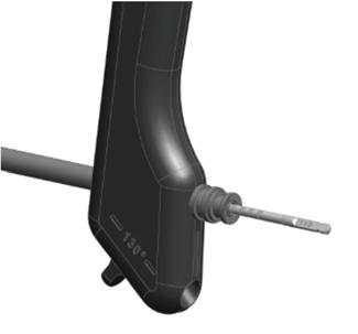
2 Implants Introduction The Nail and Lag Screw are made of longitudinal continuous carbon fiber reinforced polymer (PEEK). The screws are made of Titanium-alloy (Ti-6Al-4V). Features of the CarboFix Proximal Femur Nailing System: Anatomically shaped ProximalFemurNail with a slight bend close to its proximal end (M-L Bend) of 5 degrees, and a Caput-collum-diaphyseal angle (CCD) of 130 degrees. Lag Screw is intended for insertion through the Nail proximal screw-hole, into the femoral head. It is available in varying lengths. The Proximal Femur nail is used in an antegrade approach. For further information please refer to the product Instructions for Use. The Nail and Lag Screw are supplied sterile. Implants dimensions are as follows: Proximal Femur Nail LagScrew Screws Lag Screw Proximal Femur Nail
, which also limits Lag Screw sliding. [A Retrograde Femoral Case]")
3 SetScrew The Piccolo Composite Proximal Femur Nail is provided with both a short Set Screw ("Sliding Set Screw"), which eliminates Lag Screw rotation, but allows sliding, and a longer Set Screw ("Locking Set Screw"), which also limits Lag Screw sliding. [A Retrograde Femoral Case]
4 Instrumentation AccessGuideWire(Ø3.2mm) Marks the entry point into the medulla canal, and the trajectory. Awl Used to access the medullary canal for insertion of the Nail. The Awl can be positioned over the Access Guide Wire. EntryPortal&EntryTrocar The Entry Portal is a soft tissue protector used during soft tissue tunneling and reaming. The Entry Trocar is used for soft tissue tunneling at the access point. It accommodates a Ø3.2mm Access Guide Wire. The Trocar is locked to the Entry Portal by turning it clockwise. Ø17x300mmDrillBit Used to access the medullary canal. It is to accommodate a Ø3.2mm Access Guide Wire.
5 BallTipGuideWire(Ø2.5mm) Assists in fracture reduction, reaming and medulla canal length measurement. Compatible with conventional reamer sets. Ball Tip diameter is 4.5mm. Supplied sterile; packed separately, for single use. GuideWireRuler Measures the required nail length over the proprietary Ball-Tip Guide Wire. RadiographicRuler Used to determine the required Nail diameter and length. GuideWireExchangeTube Used for replacing the Ball-Tip Guide Wire with the Ø2.5mm Guide Wire. Supplied sterile; packed separately, for single use. GuideWire(Ø2.5mm) The Ø2.5mm Guide Wire is used for Nail insertion into the medulla canal. It may be supplied sterile; packed separately, for single use.


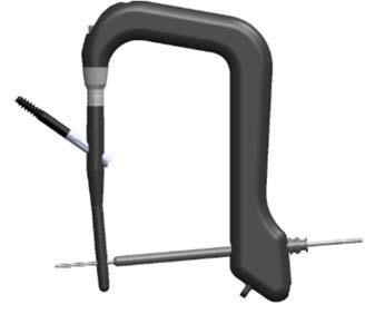
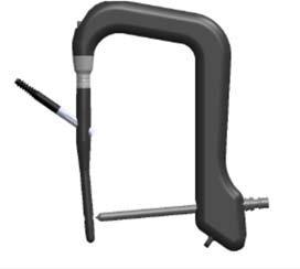
6 InsertionHandle The Insertion Handle is connected to the Nail, and enables Nail insertion ConnectionTube The Connection Tube connects and locks the Handle to the Nail proximal end. BallHexTipScrewdriver Connects to the Nail Adapter for detaching the Insertion Handle from the Nail. May also be used for connecting and detaching the Lag Screw Insertion Handle from the Lag Screw. StrikingAdapter Connects to the Insertion Handle. During Nail insertion, the surgeon can tap on it using a Mallet, or connect it to the Slide Hammer. Mallet The Mallet may be used during Nail insertion. The plastic side of the Mallet should be used for tapping the Striking Adapter gently.
7 LagScrewSleeve,LagScrewKWireSleeve&LagScrewTrocar The Sleeves provide working channel for Lag Screw insertion, and accommodate a Ø2.85mm K-Wire and the Ø10.4mm Drill Bit. The Guide & Drill Sleeves lock to each other. LagScrewKWireDepth(Ø2.85mm) Marks the entry point and trajectory for Lag Screw insertion. Supplied sterile; packed separately. KWireDepthGauge Measures the required Lag Screw length; for use with the Lag Screw K-Wire. DrillBits There are several Drill Bits in the set: Ø10.4mmStepDrillBitfor drilling the hole for the Lag Screw. Ø4.2mmStep Drill BitLong (L: 365mm) for drilling the Distal Screw hole through the Insertion Handle. It has markings along its shaft for measuring the required screw length. Ø4.2mmStepDrillBitShort(L: 180mm) for free hand drilling of the hole for the Distal Screw. Tap For Lag Screw hole tapping.
8 LagScrewDriver(LagScrewInsertionHandleAssembly) A two-component insertion handle for the Lag Screw, combined of an outer tube and an inner rod. The driver distal end design prevents relative rotation between the Lag Screw and the driver. SlidingLimitDriver An instrument designed to assess in limiting Lag Screw sliding. It is inserted via the Connection Tube, to rotate a screw located within the Nail proximal end. DistalScrewGuide&DrillSleeve,DistalScrewTrocar The Guide Sleeve is a working channel through which the Drill Sleeve and the Trocar are inserted. The Drill Sleeve accommodates the Ø4.2mm Drill Bit. The Guide & Drill Sleeves lock to each other. FreeHandDrillSleeve A working channel for Ø4.2mm Drill Bits. It is radiolucent and is used for drilling, in free hand technique, the distal screw hole(s).
9 DistalScrewDepthGauge Used to measure the required Distal Screw length. Screwdriver Used to insert or remove the Screws and the Nail Cap. PowerDriveScrewdriver For use with a power drive. NailRemovalAdapter For Nail removal; connects to the Nail proximal end as well as to the Slide Hammer. SlideHammer Used for Nail removal by connecting it to the Nail Removal Adapter. Optionally, it may be used for Nail insertion. In such cases it is connected to the Striking Adapter.

10 ProcedureSteps Note:Theentireprocessshallbeperformedunderfluoroscopicvisualization. Entry&Preparation 1. Makeskinincisionofapproximately2.5cmfromthegreatertrochantertowards theiliaccrest.achieveaccesstothebone. 2. UsetheØ3.2mmAccessKWiretomarktheentrypoint. Therearetwowaystoenterthebone: A. Use the Awl over the Access KWire to perforateanentryhole.theawldiameteris 17mm,tofitthediameteroftheNail. B. InserttheEntryTrocarintotheEntryPortal, andlockitbyrotatingitclockwise.

11 InsertThePortalAssemblyovertheKWire,so thatthekwirepassesthroughthecenterhole oftheentrytrocar; Use the adjacent holes of the Entry Trocar in ordertoimprovekwireposition,ifrequired: RotatetheEntryTrocarsothattheholes arelocatedasdesired. InsertaKWirethroughthedesiredhole, andremovetheonethatwasincorrectly placed. RemovetheEntryTrocar. Use the Ø17mm Drill Bit over the KWire to accessthebone. 3. For LongNailsInsert the BallTipGuide Wireinto the medulla canal past the fractureline.performreamingifdesired.theballtipguidewirecanbeusedwith anyconventionalintramedullaryflexiblefemoralreamingsystem,andaccording toitsinstructionsforuse.theguidewireshaftdiameteris2.5mm,andtheball Tipdiameteris4.5mm. Finalreamingshouldbe1 1.5mmlargerthantheselectedNaildiameter.


12 NailMeasurement(forLongNails) 4. MeasuretheFemurlengthanddiameterusinga RadiographicRuler. Optional: the required nail length can be measured by using the Guide Wire Ruler. A marker on the BallTip Guide Wire marks the requirednaillength. 5. Use a Guide Wire Exchange Tube to exchange the BallTip Guide Wire by the Ø2.5mmGuideWire,onwhichthenailwillbeinserted. NailInsertion 6. Connect the Handle to the Nail proximal end using theconnectiontube. Make sure the protrusions on the Insertion Handle match the grooves on the nail. Verify the nail is orientedproperly.


13 TightentheConnectionTubetotheHandleusing theballhextipscrewdriver.donotapplyhigh torque. 7. ConnecttheStrikingAdaptertotheHandle. 8. InserttheNailintothecanal,overtheGuideWire. Ifneeded,theMalletcanbeusedtoinserttheNail.Usetheplasticpartofthe MallettotapontheStrikingAdapter. Important:Donotuseexcessiveforce.UseslightstrokesonlytopositiontheNail. DonotuseoscillatingmovementstoinserttheNail.TapontheAdapteronly.


14 DuringNailinsertion,assurefracturereductionusing fluoroscopy. TheNailiscorrectlylocatedwithinthecanaloncethe Nailproximalend(theareaofconnectionoftheNail to the Insertion Handle, as can be seen using fluoroscopy) is aligned with the tip of the greater trochanter. RemovetheGuideWire. LagScrewInsertion 9. Make skin incision where Lag Screw hole is located, andachieveaccesstothebone. 10. Place the Lag Screw Sleeve, with the KWire Sleeve andkwiretrocarwithinit,insidethelagscrewhole ofthehandle.lockthesleevestothehandleusingthe lockingknobonthehandle. Locking Knob


15 Remove the Trocar and insert a Ø2.85mm KWire throughthekwiresleeve. Ensurethatthesleevesareincontactwiththelateral cortex, while verifying the anatomic position under fluoroscopy(apandlateralfluoroscopy):thekwire shallbepositionedintheinferior1/3 rd ofthecervical femur. 11. EvaluatetherequiredLagScrewlengthusingtheLag ScrewDepthGaugeovertheKWire. 12. RemovetheKWireSleeve.

16 13. UnderfluoroscopydrillaholefortheLagScrewusing the cannulated Step Drill Bit over the LagScrew K Wire.ThedistaltipoftheStepDrillBitshallgetasfar asthelagscrewdistaltipshallbelocated.verifythat thesleevesareincontactwiththebone. AstopperprovidedontheDrillBitcanbesettothe desireddrillingdepthbasedonthelagscrewlength evaluation. VerifytheLagScrewlengthaccordingtotheStep DrillBitscale.ThedistalpartoftheStepDrillBitis markedwithlinesindicatingtheavailablelagscrew lengths, at 10 mm steps, with the most proximal line corresponding to a 110 mm long Lag Screw. RemovetheStepDrillBit. Prepare the hole created for Lag Screw insertion withthehelpofthecannulatedscrewtapoverthe LagScrewKWire. RemovetheScrewTap. Stopper Length Indication


17 14. ConnecttheLagScrewDrivertotheselectedLagScrew.AligntheLagScrewDriver tubewiththerecessesatthelagscrewproximalend,androtateitsrodclockwise, tothreaditintothelagscrew. The BallHexTip Screwdriver can be used for final tightening. Do not apply high torque. 15. Insert the Lag Screw, through the Lag Screw Sleeve, while verifying proper positioning of the fracture.thelagscrewdriverismarkedwithlines indicatinginsertiondirection makesureoneof themarksisalignedwiththemarkonthehandle.
18 16. If desired compaction may be performed; rotate the knob on the Lag Screw Driver to achievethedesiredcompaction. Compactionofupto15mmcanbeachieved. 17. SelecttherequiredSetScrew. UsetheSlidingLimitDrivertoinserttheSetScrew throughtheconnectiontubeintothenailproximal end. GentlyrotatetheSetScrewwithintheNailproximal endclockwisetoslightlytightenthesetscrew. Remove the Lag Screw Driver by counterclockwise rotationofitsrod.theballhextipscrewdrivermay beused. RemovetheLagScrewSleeveandtheKWire. DistalScrews 18. Make skin incision where Distal Screw hole is located, and achieve access to the bone.
19 FortheshortNails(180,200mmlength) 19. PlacetheDistalScrewGuideSleeve,withtheDrillSleeveandTrocarwithinit,inside theappropriatehandlehole. AfterpositioningoftheSleeves,removetheTrocar. 20. Drill a holefor thescrew using the long Ø4.2mm DrillBit.DrillBitgraduationmarksmaybeusedto assessscrewlengthagainstthedrillsleeve. RemovetheDrillBitandDrillSleeve.
. 22.")
 23.")
20 21. Select the appropriate length of the Ø5.0mm Screw, by using the Distal Screw Depth Gauge and/orthedrillbitgraduationmarks(asindicated above). 22. InserttheScrewthroughtheGuideSleeve,by using the Screwdriver (Power Screwdriver couldalsobeused). RemovetheScrewdriverandGuideSleeve. Note:Alternatively, freehand drillingmaybeperformed;insuchcase,please Followthenextsteps. FortheLongNails( mmlength) 23. Distaldrillingisperformedin freehand technique. Tinytantalumrodsmarkers,locatednearthedistalholes,assistinlocatingthe centeroftheholes.
21 Uponproperpositioning,whilethexraybeamisperpendiculartothehole,the2 radiopaquemarkersateachsideoftheholeshouldbealignedintoasingledot.in properpositioningasingledotshouldbeseenateachsideofthehole. Radiopaque Markers Holefor Screw Radiopaque Markers Holefor Screw DrillaholefortheInterlockingScrewusingthe short Ø4.2mm Step Drill Bit through the Free HandDrillSleeve,infreehandtechnique. 24. SelecttheappropriatelengthoftheØ5.0mmScrew,byusingtheDistalScrewDepth Gauge. 25. InserttheScrewbyusingtheScrewdriver(PowerScrewdrivercouldalsobeused). X IncorrectAlignmentofMarkersfor DistalScrewsInsertion Correct AlignmentofMarkersforDistal ScrewsInsertion

22 NailCapInsertion 26. RemovetheConnectionTube(counterclockwise rotation)anddisconnectthehandlefromthe Nail. 27. The Nail Cap shall be inserted by using the Screwdriver. There are 3 available Nail Cap lengths: 0, 5 & 10mm. TheNail Capincorporates twoembedded radiopaque markersforvisualization underfluoroscopy. 28. Closethebonepenetrationpointsaccordingtothesurgicalprocedure.
23 NailRemoval 1. Makeskinincisionandexposetheboneentryhole. 2. ConnecttheScrewdrivertotheNailCapattheNailproximal end,andremovethecapbycounterclockwiserotation. 3. UsetheSlidingLimitDrivertoreleasetheLagScrew rotate thesetscrewcounterclockwise. 4. MakeskinincisionwherethedistalScrewislocated.Usingthe Screwdriver,removetheScrewbycounterclockwiserotation. 5. MakeskinincisionwheretheLagScrewislocated.Connectthe LagScrewDrivertotheLagScrewandremovetheLagScrew bycounterclockwiserotation. 6. ScrewtheNailRemovalAdapterontothenail sproximalend. 7. ConnecttheSlideHammertotheNailRemovalAdapter. UselightstrokesoftheSlideHammertoremovetheNail fromthebone. 8. Closethepenetrationpointsaccordingtothesurgical procedure.

24 Fordetailedprocedure,indications,contraindications,possibleadverseevent,warningsandprecautions,refertotheInstructionsforUse Caution:IntheU.S.A.,federallawrestrictsthisdevicetosalebyorontheorderofaphysician. 1 MANUFACTURED BY: U.S.A.OFFICE: ECAUTHORIZED REPRESENTATIVE: CarboFix OrthopedicsLtd. 11Ha hoshlimst., Herzeliya ,Israel Tel: Fax: info@carbofix.com CarboFix OrthopedicsInc Beach Drive SW Ocean Isle Beach, NC 28469, USA Tel: usa@carbofix.com MEDNETGmbH Borkstrasse10,48163Münster Germany Ver.002_ Patentsarepending
Humeral Nail System Procedural Steps.
 Humeral Nail System Procedural Steps www.carbo-fix.com Table of Contents Introduction..3 Instrumentation Set... 8 Procedural Steps: Humeral Nail.........10 Procedural Steps: Proximal Humeral Nail.....13
Biomet Peritrochanteric Nail (PTN) System. Surgical Technique
 System. Surgical Technique") Biomet Peritrochanteric Nail (PTN) System Surgical Technique Contents Introduction... Page 1 Indications... Page 2 OTA Femoral Fracture Classifications... Page 3 Surgical Technique... Page 4 Patient Positioning...
Biomet Peritrochanteric Nail (PTN) System Surgical Technique Contents Introduction... Page 1 Indications... Page 2 OTA Femoral Fracture Classifications... Page 3 Surgical Technique... Page 4 Patient Positioning...
S U R G I C A L T E C H N I Q U E TRAUMA & EXTREMITIES GROUP
 S U R G I C A L T E C H N I Q U E TRAUMA & EXTREMITIES GROUP TABLE OF CONTENTS ATN NAIL SYSTEM DESIGN RATIONALE INDICATIONS/CONTRAINDICATIONS PREOPERATIVE PLANNING AND PATIENT POSITIONING NAIL INSERTION
Orthopedic Bone Nail System Universal Humeral Nail
 Orthopedic Bone Nail System Universal Humeral Nail Surgical Technique Manual Note: The surgical procedures should be performed under the guidance of qualified skilled orthopedic surgeons, and this surgical
Zimmer Natural Nail System
 Zimmer Natural Nail System Cephalomedullary Small Nail Surgical Technique Table of Contents Product Overview... 2 Implant Overview... 2 Indications... 3 Contraindications... 3 Surgical Technique... 4 Preoperative
Zimmer Natural Nail System. Cephalomedullary Nail Surgical Technique SMALL
 Zimmer Natural Nail System Cephalomedullary Nail Surgical Technique SMALL Zimmer Natural Nail System Cephalomedullary Nail Technique - Small 1 Zimmer Natural Nail System Cephalomedullary Nail Surgical
Universal Humeral Nail
 990210009 INDEX Indications Preoperative Planning Patient Position Surgical Technique - Step 1 Open Humerus - Step 2 Calibrate The Nail - Step 3 Insert Nail - Step 4 Proximal Locking - Step 5 Assemble
Introduction TRIGEN META-TAN Nail specifications Surgical technique Patient positioning Opening the proximal femur Intramedullary reaming
 Surgical Technique Table of contents Introduction... 2 TRIGEN META-TAN Nail specifications... 3 Surgical technique... 4 Patient positioning... 4 Opening the proximal femur... 5 Incision and entry point...
The CentroNail System: Universal Femoral Nailing Applications
 O P E R A T I V E T E C H N I Q U E The CentroNail System: Universal Femoral Nailing Applications 1 2 3 FEATURES AND BENEFITS Proximal locking Locking screws 4 INDICATIONS 5 EQUIPMENT REQUIRED 9 17 26
Distal Volar Radius Plate Procedure Steps.
 Distal Volar Radius Plate Procedure Steps www.carbo-fix.com Introduction The CarboFix Implants The CarboFix Distal Volar Radius Plates are made of numerous continues carbon fibers embedded in polymer (PEEK).
The Titanium Cannulated Lateral Entry Femoral Recon Nail. Expert nailing system with radiolucent instrumentation.
 The Titanium Cannulated Lateral Entry Femoral Recon Nail. Expert nailing system with radiolucent instrumentation. Technique Guide EXPERT Nailing System Table of Contents Introduction Titanium Cannulated
Zimmer Natural Nail System
 Zimmer Natural Nail System Cephalomedullary Nail Surgical Technique Compact Case- Short Nails Only SMALL Zimmer Natural Nail System Cephalomedullary Nail Technique - Small 1 Zimmer Natural Nail System
Zimmer Natural Nail System
 Zimmer Natural Nail System Cephalomedullary Nail Surgical Technique Compact Case - Short Nails Only STANDARD Zimmer Natural Nail System Cephalomedullary Nail Surgical Technique - Standard 1 Zimmer Natural
OPERATIVE TECHNIQUE. The Centronail Titanium Universal Femoral Nailing System
 OPERATIVE TECHNIQUE The Centronail Titanium Universal Femoral Nailing System 1 2 3 FEATURES AND BENEFITS Proximal locking Locking screws 4 INDICATIONS 5 EQUIPMENT REQUIRED 9 17 26 28 ANTEGRADE INSERTION
EX NAIL INSTRUMENTATION
 EX NAIL INSTRUMENTATION PRODUCT OVERVIEW OPENING INSTRUMENTS Awl Description Cannulated to accommodate a 3.0 mm Ball Tipped Reaming Rod 03.037.008 8.0 mm Cannulated Curved Awl Wire Guide Accessory Removable
Pocket Reference Cards
 Stryker Nailing T2 Pocket Reference Cards Tibial Nails Femoral Nails Humeral Nails T2 Arthrodesis Nails Flexible Nails General Notes The following notes apply to all T2 IM Nails (except T2 Kids) unless
Gamma3 Trochanteric Nail 170 & 180. Operative technique
 Gamma3 Trochanteric Nail 170 & 180 Operative technique Gamma3 Trochanteric Nail 170 & 180 Contents 1. Design of the Gamma3 System....4 Gamma Nail 170 and 180... 4 Distal locking screws... 5 2. Indications
Features and Benefits 2. Indications and Pre-op Planning 7. Patient Positioning and Reduction 8. Entry and Canal Preparation 9.
 S U R G I C A L T EC H N I Q U E Contents Features and Benefits 2 Indications and Pre-op Planning 7 Patient Positioning and Reduction 8 Entry and Canal Preparation 9 Nail Insertion 12 Proximal Locking
Operasjonsteknikk. Retrograd Femur
 Operasjonsteknikk Retrograd Femur TRIGEN META-NAIL Retrograde Femoral Nail System Surgical Technique Table of Contents Indications...2 Implant Specifications...3 Surgical Technique Patient Positioning...4
Ankle Fracture System. Surgical Technique STRENGTH FROM WITHIN
 Ankle Fracture System Surgical Technique STRENGTH FROM WITHIN Ankle Fracture System The Sonoma FibuLock nail is the first intramedullary device that has the same indications as plates and delivers anatomic
Knee Nail for Retrograde Femoral Mode
 Surgical Technique *smith&nephewt TRIGEN IM Nail System Knee Nail for Retrograde Femoral Mode Table of Contents Indications 2 Surgical Technique 3 TRIGEN STABLE-LOK Nut & Washer Surgical Technique 16 TRIGEN
The Percutaneous Reduction Forceps Technique Guide
 The Percutaneous Reduction Forceps Technique Guide Indications + Product Overview Introduction The Percutaneous Reduction Forceps The Percutaneous Reduction Forceps facilitate standard technique for fixation
Surgical Technique Guide
 Surgical Technique Guide Patented - www.flow-fx.net Flow-FX, LLC 9301 W 191st Street Mokena, IL 60448 P. 815.531.4424 by Flow-FX, LLC. 2017 Products referenced with TM are trademarks of Flow-Fx. STG-101
TALON DISTALFIX Proximal Femoral Nail. Surgical Technique
 TALON DISTALFIX Proximal Femoral Nail Surgical Technique TALON DISTALFIX SLN-Nail Surgical Technique Table of Contents Introduction 3 TALON DISTALFIX SLN-Nail 3 Design Features 4 Indications/Contraindications
Surgical Technique. Customer Service:
 Patent Pending CAUTION: Federal Law (USA) restricts this device to sale by or on the order of a physician. Notes This page is blank INDICATIONS FOR USE The Extremity Medical Hallu X Intramedullary Fusion
Technique Chart. DHS/DCS One-Step Insertion Wrench. For use with DHS/DCS One-Step Lag Screws.
 Technique Chart DHS/DCS One-Step Insertion Wrench. For use with DHS/DCS One-Step Lag Screws. DHS/DCS One-Step Insertion Wrench DHS Triple Reamer (338.13) Assembly 338.10 8.0 mm Drill Bit 338.11 DHS Reaming
Gamma3 Long Nail R1.5 and R2.0. Operative technique
 Gamma3 Long Nail R1.5 and R2.0 Gamma3 Long Nail R1.5 and R2 Gamma3 Long Nail R1.5 and R2.0 Contents 1. Design of the Gamma3 System...4 Lag screw and set screw function... 5 Distal locking screws... 5 2.
OR manual. PLATON ti) )))
 )))") OR manual PLATON ti) Characteristics of the PLATON ti system Variation I dynamic with sliding distance limitation Variation II AR Clip dynamic with sliding distance limitation PLATON ti-s PLATON ti-l Proximal
OR manual PLATON ti) Characteristics of the PLATON ti system Variation I dynamic with sliding distance limitation Variation II AR Clip dynamic with sliding distance limitation PLATON ti-s PLATON ti-l Proximal
Technique Guide Supplement. Standard DHS Lag Screw with LCP DHHS Sideplate.
 Technique Guide Supplement Standard DHS Lag Screw with LCP DHHS Sideplate. Table of Contents Surgical Technique Standard DHS Lag Screw with LCP DHHS 2 Sideplate Technique DHS One-step Lag Screw with DHHS
The Universal Nail System TECHNIQUE GUIDE
 The Universal Nail System TECHNIQUE GUIDE R Original Instruments and Implants of the Association for the Study of Internal Fixation AO ASIF Table of Contents.. THE..... UNIVERSAL............ NAILS............................
Carpal Tunnel Ligament Release
 Hip T2 KnifeLight Recon Nailing System R2.0 Carpal Tunnel Ligament Release Femur Operative Technique Operative Technique Hip & Femur Fractures T2 Recon Nailing System Contributing Surgeons We greatly acknowledge
Surgical Technique International Version
 Surgical Technique International Version TRIGEN INTERTAN Intertrochanteric Antegrade Nail Surgical Technique As described by: Professor Dr. med. J.M. Rueger Thomas A. Russell, MD Roy W. Sanders, MD Paul
Carpal Tunnel Ligament Release
 Hip Gamma3 KnifeLight Trochanteric Nail 180 Carpal Tunnel Ligament Release Operative Technique Operative Technique Hip Fractures Trochanteric Nail 180 Contributing Surgeons Prof. Kwok Sui Leung, M. D.
OsteoBridge IKA Intramedullary Knee Arthrodesis Fixation System. From the «BioBall Company» OsteoBridge Family
 From the «BioBall Company» OsteoBridge Family OsteoBridge IKA Intramedullary Knee Arthrodesis Fixation System The modular system for the fixation of the knee joint 01. OsteoBridge IKA The OsteoBridge IKA
Operative Technique Hip Fracture Systems
 Gamma3 Trochanteric Nail 180 Operative Technique Hip Fracture Systems Trochanteric Nail 180 Contributing Surgeons: Prof. Kwok Sui Leung, M. D. Chairman of Department of Orthopaedics and Traumatology The
Aesculap Orthopaedics Targon F/T
 esculap Orthopaedics Targon F/T Interlocking Nail System for Femur and Tibia Operation Technique F/T for strong connections The Targon interlocking nail system is the result of years of clinical experience
Expert HAN. Expert Hindfoot Arthrodesis Nail.
 Expert HAN. Expert Hindfoot Arthrodesis Nail. Technique Guide Expert Nailing System Table of Contents Introduction Expert Hindfoot Arthrodesis Nail 2 AO Principles 4 Indications 5 Surgical Technique Preoperative
6.5 mm and 7.3 mm Cannulated Screws Technique Guide
 6.5 mm and 7.3 mm Cannulated Screws Technique Guide An Integral Part of the SYNTHES Cannulated Screw System Original Instruments and Implants of the Association for the Study of Internal Fixation AO ASIF
Vortex TRAUMATOLOGY. Vortex Distal Femur
 Vortex TRAUMATOLOGY Vortex Distal Femur 1 Content 1. Introduction 4 4. Implant list 16-17 The following surgical description contains general outlines for Vortex Distal Femur plating. However, the operating
T2 Recon Nailing System
 Osteosynthesis T2 Recon Nailing System Operative Technique Contributing Surgeons: Kyle F. Dickson, MD, MBA Professor and Chairman University of Texas Medical School at Houston Department of Orthopaedic
OPERATIVE TECHNIQUE RIVAL BITE HEADED CANNULATED AND HEADLESS COMPRESSION SCREWS. foot & ankle applications
 OPERATIVE TECHNIQUE RIVAL BITE HEADED CANNULATED AND HEADLESS COMPRESSION SCREWS foot & ankle applications INTRODUCTION 3 SYSTEM DESCRIPTION 3 TECHNICAL DETAILS 4 SALES AND MARKETING CONFIGURATION 6 OPERATIVE
HipHip Fracures. Gamma3. Trochanteric Nail 180
 HipHip Fracures Gamma3 Trochanteric Nail 180 Gamma3 Trochanteric Nail 180 Contributing Surgeons Prof. Kwok Sui Leung, M. D. Chairman of Department of Orthopaedics and Traumatology The Chinese University
Instructions for Use. LCP Locking Compression Plate. Combine without Compromise.
 Instructions for Use LCP Locking Compression Plate. Combine without Compromise. Table of Contents LCP: Combine without Compromise 2 AO ASIF Principles of Osteosynthesis 4 Indications and Contraindications
Surgical Technique. Including
 Surgical Technique Including TRIGEN META-NAIL Retrograde Femoral Nail System Surgical Technique Table of contents Indications...2 Implant specifications... 4 Surgical technique Patient positioning...
Aesculap Orthopaedics Targon RF. Retrograde Femoral Nail
 Aesculap Orthopaedics Targon RF Retrograde Femoral Nail Retrograde Femoral Nail The implantation of interlocking nails from an antegrade access has become the gold standard for most fractures of the femoral
Technique Guide. LCP Dynamic Helical Hip System (DHHS). Part of the Synthes Large Fragment LCP System.
. Part of the Synthes Large Fragment LCP System.") Technique Guide LCP Dynamic Helical Hip System (DHHS). Part of the Synthes Large Fragment LCP System. Table of Contents Introduction LCP Dynamic Helical Hip System (DHHS) 2 AO Principles 4 Indications
Technique Guide LCP Dynamic Helical Hip System (DHHS). Part of the Synthes Large Fragment LCP System. Table of Contents Introduction LCP Dynamic Helical Hip System (DHHS) 2 AO Principles 4 Indications
HCS 2.4/3.0. The countersinkable compression screw.
 Technique Guide HCS 2.4/3.0. The countersinkable compression screw. Table of Contents Introduction Features and Benefits 2 Functional Principle 3 Indications 4 Surgical Technique Hand Scaphoid 5 Foot
Humerus. Humeral Nailing System. Humeral Fractures
 Humerus T2 Humeral Nailing System Humeral Fractures Operative Technique T2 Humeral Nailing System Contributing Surgeons Rupert Beickert, M. D. Senior Trauma Surgeon Murnau Trauma Center Murnau Germany
SURGICAL TECHNIQUE INSTRUMENT SET FOR NAIL EXTRACTION
 SURGICAL TECHNIQUE INSTRUMENT SET FOR NAIL EXTRACTION Instructions for use of the set for nail extraction PL0236. The nail assortment for which the set is intended: Medical device description Indications:
VECTRA SURGICAL TECHNIQUE. Anterior cervical plate system. This publication is not intended for distribution in the USA.
 VECTRA Anterior cervical plate system This publication is not intended for distribution in the USA. SURGICAL TECHNIQUE Image intensifier control This description alone does not provide sufficient background
Technique Guide. 4.5 mm Cannulated Screws. Part of the Synthes Cannulated Screw System.
 Technique Guide 4.5 mm Cannulated Screws. Part of the Synthes Cannulated Screw System. TableofContents Introduction 4.5 mm Cannulated Screws 2 AO Principles 3 Indications 4 Surgical Technique Surgical
Gamma3 Trochanteric Nail 170
 Gamma3 Trochanteric Nail 170 Operative Technique Hip Fracture Trochanteric Nail 170 Contributing Surgeons: Prof. Kwok Sui Leung, M. D. Chairman of Department of Orthopaedics and Traumatology The Chinese
VECTRA. SURGICAL TECHNIQUE. Anterior cervical plate system. This publication is not intended for distribution in the USA.
 VECTRA. Anterior cervical plate system. This publication is not intended for distribution in the USA. SURGICAL TECHNIQUE Contents Indications and contraindications Implants Vario Case Instruments Surgical
Technique Guide. 7.0 mm Cannulated Screws. Part of the Synthes Cannulated Screw System.
 Technique Guide 7.0 mm Cannulated Screws. Part of the Synthes Cannulated Screw System. Table of Contents Introduction 7.0 mm Cannulated Screws 2 AO Principles 3 Indications 4 Surgical Technique Surgical
Integra. Capture Screw System SURGICAL TECHNIQUE
 Integra Capture Screw System SURGICAL TECHNIQUE Table of Contents Indications... 2 Contraindications... 2 System Description... 2 System Features... 2 Cannulated Low-Profile Screws (AC-Series) Overview...
Surgical Technique ANAX TM OCT. Spinal System
 Surgical Technique ANAX TM OCT Spinal System Product Overview Occipital plate Medial occipital plate (Small, Medium, Large) Lateral occipital plate (Small, Medium, Large) Cortical screw (D4.5mm), Rescue
Interlagos Retractor System Surgical Technique
 Interlagos Retractor System Surgical Technique TABLE OF CONTENTS Instructions for Use Design Rationale Surgical Technique 1. Pre-Operative Preparation 2. Pedicle Preparation 3. Primary Retraction 4. Secondary
DLS Dynamic Locking Screw. Combined with LCP Locking Compression Plate.
 DLS Dynamic Locking Screw. Combined with LCP Locking Compression Plate. Instructions for Use Discontinued June 2016 DSEM/TRM/0517/0844(1) Table of Contents Introduction DLS Dynamic Locking Screw 2 Indications
Cannulated Screws Ø 3.5 mm / 4.5 mm
 Cannulated Screws Ø / 4.5 mm Table of contents Implants Ø 4 Implants Ø 4.5 mm 6 Operation technique - Ø Cannulated Screws 9 Reduce fracture and insert guide wire 9 Determine the screw length 9 Drilling
OPERATIVE TECHNIQUE RIVAL REDUCE FRACTURE PLATING SYSTEM. foot & ankle trauma procedures
 OPERATIVE TECHNIQUE RIVAL REDUCE FRACTURE PLATING SYSTEM foot & ankle trauma procedures INTRODUCTION 3 SYSTEM DESCRIPTION 3 TECHNICAL DETAILS 4 SALES AND MARKETING CONFIGURATION 5 OPERATIVE TECHNIQUE 7
Omega 3 System Compression Hip Screw
 Omega 3 System Compression Hip Screw Hip Fracture Axially Stable Locking Option Contents Omega3 Compression Hip Screw Introduction 4 Potential Features & Benefits 5 Relative Indications & Contraindications
DISTAL RADIUS PLATES 3.5 mm / ANGULARLY STABLE. Distal radius plates 3,5 mm / angularly stable. Locking bone screws. Cortical bone screw
 SURGICAL NÁSTROJE TECHNIQUE PRO ARTROSKOPII DISTAL INSTRUMENTS RADIUS PLATES FOR ARTHROSCOPY 3.5 mm / ANGULARLY STABLE Distal radius plates 3.5 mm / angularly stable Indication The plates are used for
Operative Technique Hip Fracture Systems
 Gaa3 Long Nail R2.0 Operative Technique Hip Fracture Systems Gaa3 Long Nail R2.0 Contributing Surgeons: Prof. Kwok Sui Leung, M. D. Chairman of Department of Orthopaedics and Traumatology The Chinese University
A free-extending two part cannulated screw that will elongate with growth. SURGICAL TECHNIQUE
 A free-extending two part cannulated screw that will elongate with growth. SURGICAL TECHNIQUE The Free-Gliding SCFE Screw System, designed to treat the most common hip problem in growing children, SLIPPED
PRE-OPERATIVE PREPARATIONS
 SURGICAL TECHNIQUE PRE-OPERATIVE PREPARATIONS Pre-operative X-ray will help to determine the diameter of the nail to be used. Using X-ray of uninjured femur may also help in determining diameter and length
LCP Pilon Plate 2.7/3.5
 Surgical Technique LCP Locking Compression Plate Original Instruments and Implants of the Association for the Study of Internal Fixation AO/ASIF Table of contents Indications 3 Implants 4 Instruments 5
Aesculap Orthopaedics Targon PFT
 Aesculap Orthopaedics Targon PFT Intramedullary Nail For Proximal Femoral Fractures...because two are better than one Targon PFT Priv. Doz. Dr. H.-W. Stedtfeld, Centre for Trauma Surgery, Nuremberg, Germany
Digital Compression Screw
 Digital Compression Screw Surgical Technique Contents Product The BioPro Digital Compression Screw is a stainless steel lag screw designed for digital fusions. Table of contents Indications & Contraindications
Instruments for Removing DePuy Synthes Screws. Screw Removal Set
 Instruments for Removing DePuy Synthes Screws Screw Removal Set Surgical Technique Table of Contents Introduction Screw Removal Set 2 Surgical Technique Preoperative Planning and Preparation 6 Removal
Rotator Cuff Repair ICONN Answer PEEK Suture Anchor 4.75/5.5. Surgical Protocol by Geoffrey Connor, 4.75/5.5 MD of D1 Sports Medicine
 Rotator Cuff Repair ICONN Answer PEEK Suture Anchor 4.75/5.5 Surgical Protocol by Geoffrey Connor, 4.75/5.5 MD of D1 Sports Medicine ICONN s revolutionary approach is to drive value into every aspect of
Lag Screw Device TECHNIQUE GUIDE. Indicated for symphyseal fracture fixation of the mandible. Instruments and implants approved by the AO Foundation
 Lag Screw Device TECHNIQUE GUIDE Indicated for symphyseal fracture fixation of the mandible Instruments and implants approved by the AO Foundation Lag Screw Device Indicated for symphyseal fracture fixation
ACCS Anterior Cervical Compression System TECHNIQUE GUIDE
 ACCS Anterior Cervical Compression System TECHNIQUE GUIDE Original Instruments and Implants of the Association for the Study of Internal Fixation AO ASIF ACCS Anterior Cervical Compression System The Anterior
Technique Guide. Synapse System. An enhanced set of instruments and implants for posterior stabilization of the cervical and upper thoracic spine.
 Technique Guide Synapse System. An enhanced set of instruments and implants for posterior stabilization of the cervical and upper thoracic spine. Table of Contents Introduction Synapse System 2 AO Principles
Technique Guide. LCP Pilon Plate 2.7/3.5
 Technique Guide LCP Pilon Plate 2.7/3.5 LCP Pilon Plate 2.7/3.5 Table of contents Indications 3 Implants 4 Instruments 5 Surgical technique 6 Implant removal 12 Image intensifier control Warning This
Mecron Cannulated Screws
 Surgical Technique and Ordering Information 2 Table of contents Description... 4 Indications for use... 4 Contraindications... 4 State-of-the-art design features... 5 Surgical Technique... 6 Surgery Steps
Integra. Stainless Headed Compression Screw System SURGICAL TECHNIQUE
 Integra Stainless Headed Compression Screw System SURGICAL TECHNIQUE Table of Contents Design Rationale...2 Indications...2 Contraindications...2 Surgical Technique Step 1: Inserting Guide Wire... 3 Step
D. Greg Anderson, MD Thomas Jefferson University Hospital Philadelphia, PA
 Surgical Technique D E S I G N I N G S U R G E O N S D. Greg Anderson, MD Thomas Jefferson University Hospital Philadelphia, PA Robert Heary, MD University of Medicine and Dentistry of New Jersey Newark,
Cervical Solutions. Lineum OCT. Spine System. Surgical Technique Guide
 Cervical Solutions Lineum OCT Spine System Surgical Technique Guide 2 Lineum OCT Spine System Surgical Technique Guide Designed to encourage optimal screw placement and procedural efficiency Lineum OCT
4.0 CANNULATED SCREW SYSTEM
 Surgical Technique 4.0 CANNULATED SCREW SYSTEM Surgical technique Table of contents Design features...2 Indications...3 Surgical technique...4 Inserting the screw...4 Extracting the screw...6 Catalog
HCS 1.5. The countersinkable compression screw.
 HCS 1.5. The countersinkable compression screw. Surgical Technique This publication is not intended for distribution in the USA. Instruments and implants approved by the AO Foundation. Table of Contents
WRIST SYSTEM. ARIX Volar Distal Radius Locking Plate System
 WRIST SYSTEM A Contents 3 4 7 14 15 16 19 21 Indications Product Overview Features & Benefits Ordering Information - Screws -2.5mm Self-Tapping Cortical Screws (Non-Locking) -2.5mm Self-Tapping Locking
Distal Medial Tibia Plate Surgical Technique
 Locking Compression Technology by aap 1 Disclaimer This surgical technique is exclusively intended for medical professionals, especially physicians, and therefore may not be regarded as a source of information
VLP FOOT Variable Angle Locked Plating System
 Surgical Technique VLP FOOT Variable Angle Locked Plating System Surgical Technique Table of Contents Product overview Implant selection...2 Introduction...3 System overview...4 Indications...4 Design
Technique Guide. Cable System. For Orthopaedic Trauma Surgery.
 Technique Guide Cable System. For Orthopaedic Trauma Surgery. Table of Contents Introduction Overview 2 AO Principles 4 Indications and Contraindications 5 Surgical Technique Standard Cerclage Technique
Cerclage Passer. For minimally invasive application of cerclage cables.
 Cerclage Passer. For minimally invasive application of cerclage cables. Handling Technique Cable application This publication is not intended for distribution in the USA. Instruments and implants approved
SURGICAL TECHNIQUE GUIDE
 SURGICAL TECHNIQUE GUIDE DANGER indicates an imminently hazardous situation which, if not avoided, will result in death or serious injury. WARNING indicates a potentially hazardous situation which, if
Technique Guide. Variable Angle LCP 1 st MTP Fusion Plates 2.4/2.7. Part of the Variable Angle LCP Forefoot / Midfoot System 2.4 / 2.7.
 Technique Guide Variable Angle LCP 1 st MTP Fusion Plates 2.4/2.7. Part of the Variable Angle LCP Forefoot / Midfoot System 2.4 / 2.7. Table of Contents Introduction Variable Angle LCP 1 st MTP Fusion
OPERATIVE TECHNIQUE RIVAL VIEW PLATING SYSTEM. foot & ankle reconstruction procedures
 OPERATIVE TECHNIQUE RIVAL VIEW PLATING SYSTEM foot & ankle reconstruction procedures INTRODUCTION 3 SYSTEM DESCRIPTION 3 TECHNICAL DETAILS 4 SALES AND MARKETING CONFIGURATION 5 OPERATIVE TECHNIQUE 7 OPERATIVE
5th Metatarsal Fracture System Surgical Technique
 5th Metatarsal Fracture System Surgical Technique 5th Metatarsal Fracture System 5th Metatarsal Fracture System The 5th Metatarsal Fracture System (AR-8956S) is a uniquely designed screw and plate system
ACLP Anterior Cervical Locking Plate System TECHNIQUE GUIDE
 ACLP Anterior Cervical Locking Plate System TECHNIQUE GUIDE Instruments and implants approved by the AO Foundation ACLP Anterior Cervical Locking Plate System The ACLP System is designed to reduce the
CLOUS PFN-G PFN-G NAILS. Viseur radio transparent Radiolucent insertion handle 1-1
 CLOUS PFN-G PFN-G NAILS Viseur radio transparent Radiolucent insertion handle 1-1 CLOUS PFN-G PFN-G NAILS Clou PFN-G long PFN-G long nail 11 300 ~ 420 Type Droite / Right Droite / Right Angle 130 135 302231~237
MTP Set SURGICAL TECHNIQUE
 MINI MAXLOCK EXTREME MTP Set SURGICAL TECHNIQUE Contents Table of Contents Key Design Features 3 Surgical Technique Standard MTP Plate 4 MTP Plate with POCKETLOCK Technology 10 Implants and Instruments
Technique Guide. 2.4/2.7 mm Locking Tarsal Plates. Talus Plate, Navicular Plate and Cuboid Plate.
 Technique Guide 2.4/2.7 mm Locking Tarsal Plates. Talus Plate, Navicular Plate and Cuboid Plate. Table of Contents Introduction 2.4/2.7 mm Locking Tarsal Plates 2 AO Principles 4 Indications 5 Clinical
SpeedTip CCS 5.0, 7.0
 SURGICAL TECHNIQUE STEP BY STEP SpeedTip CCS 5.0, 7.0 Cannulated Compression Screws APTUS 2 SpeedTip CCS 5.0, 7.0 Cannulated Compression Screws Contents 3 Introduction Product Materials Indications Contraindications
7.0 mm Cannulated Screws
 Part of the DePuy Synthes Cannulated Screw System 7.0 mm Cannulated Screws Surgical Technique Table of Contents Introduction 7.0 mm Cannulated Screws 2 AO Principles 3 Indications 4 Surgical Technique
LCP Pilon Plate 2.7/3.5
 LCP Pilon Plate 2.7/3.5 Surgical Technique This publication is not intended for distribution in the USA. Instruments and implants approved by the AO Foundation. Table of contents Indications 2 Implants
1.5 MM LCP SYSTEM. For treatment of fractures and arthrodeses of canines and felines SURGICAL TECHNIQUE
 1.5 MM LCP SYSTEM For treatment of fractures and arthrodeses of canines and felines SURGICAL TECHNIQUE TABLE OF CONTENTS INTRODUCTION 1.5 mm LCP System 2 AO Principles 4 SURGICAL TECHNIQUE Reduce Fracture
Locking Small Fragment
 Locking Small Fragment Page 1 Locking Small Fragment Table of contents Implants 5 Operation technique 7 Inserting drill guides 7 Drilling 7 Length measurement 7 Inserting the measured screw 8 Different
Anterior Cervical Plate SURGICAL TECHNIQUE GUIDE. Surgeon Driven Innovation
 Anterior Cervical Plate SURGICAL TECHNIQUE GUIDE Surgeon Driven Innovation 1 The Snowmass Anterior Cervical Plate System is intended for the surgical treatment and correction of traumatic and pathologic
For Minimally Invasive Application of Cerclage Wires. Cerclage Passer. Surgical Technique
 For Minimally Invasive Application of Cerclage Wires Cerclage Passer Surgical Technique Table of Contents Introduction Cerclage Passer 2 Surgical Technique Preparation 4 Insert Cerclage Passer 5 Connect