OPERATIVE TECHNIQUE RIVAL VIEW PLATING SYSTEM. foot & ankle reconstruction procedures
|
|
|
- Clarissa Warner
- 6 years ago
- Views:
Transcription

1 OPERATIVE TECHNIQUE RIVAL VIEW PLATING SYSTEM foot & ankle reconstruction procedures
2 INTRODUCTION 3 SYSTEM DESCRIPTION 3 TECHNICAL DETAILS 4 SALES AND MARKETING CONFIGURATION 5 OPERATIVE TECHNIQUE 7
3 OPERATIVE TECHNIQUE 3 INTRODUCTION This operative technique explains the recommended procedures for using the RIVAL VIEW Plating System s devices and instruments. Please refer to the corresponding instructions below on specific steps. The IFU (Instruction For Use) leaflet contains the indications for use as well as the contraindications and has been included in the packaging of all implants. It can also be found at SYSTEM DESCRIPTION The RIVAL VIEW Plating System includes titanium alloy, sterile packed Lapidus, First Metatarsophalangeal (MTP), Calcaneal-Cuboid (CC), Evans Osteotomy and Talonavicular (TN) plates along with sterile titanium alloy bone screws. The RIVAL VIEW Plates have been developed to utilize a perimeter loading design. The shape of RIVAL VIEW creates a window, offering a possibility to monitor the healing process of the fracture or osteotomy. The RIVAL VIEW Plating System is offered in a variety of sizes for use with the RIVAL non-locking and locking bone screws. The screws are available in a variety of diameters and lengths. The corresponding instrumentation necessary for insertion is found in Orthofix s RIVAL Instrumentation.
 Small, Medium, Large Small, Medium, Large 6mm, 8mm, 10mm, 12mm Spacers Plate Specifics Anatomic Right and Left specific Anatomic")

4 4 OPERATIVE TECHNIQUE TECHNICAL DETAILS Table 1: RIVAL VIEW Plating System PLATES MTP Lapidus Talonavicular (TN) Calcaneal-cuboid (CC) Evans Osteotomy Plate Thickness 1.5mm 1.8mm 2.0mm 1.5mm 2.0mm Plate Sizes Small, Medium, Large Small, Large (Flat and 2mm Step) Small, Medium, Large Small, Medium, Large 6mm, 8mm, 10mm, 12mm Spacers Plate Specifics Anatomic Right and Left specific Anatomic Anatomic Anatomic Anodization Vector Purple Gold Magenta Blue Vector Purple BONE SCREWS 2.7mm Locking 2.7mm Non- Locking 3.2mm Locking 3.2mm Non-Locking Size Range 8 to 40 mm 8 to 40 mm 10 to 50mm 10 to 50mm Length Increments 2mm 2mm 2mm 2mm Drill Size 2mm 2mm 2mm 2mm Anodization Gun Metal Gray Gun Metal Gray Gold Gold RIVAL Instrument Set - Top Tray Q.ty 001-A Parallel Wire Guide, 4.0/4.5mm Screw A Paralle Wire Guide, 6.5/8.0mm Screws A Small Depth Gauge, 0.9mm, 1.1mm and 1.5mm Guide 1 Wires 001-A Large Depth Gauge, 2.8mm Guide Wire A Small Ratcheting Handle, Cannulated, A Medium Ratcheting Handle, Cannulated, A Large Ratcheting Handle, Cannulated, A Cannulated Cruciform Driver, 2.0/2.5mm Headed Screw, A Cannulated Cruciform Driver, 3.0/3.5mm Headed Screw, A Cannulated Cruciform Driver, 4.0/4.5mm Headed Screw, A Cannulated Cruciform Driver, 6.5/8.0mm Headed Screw, A Cannulated Hex Driver, 2.0/2.5mm Headless Screw, A Cannulated Hex Driver, 3.0/3.5mm Headless Screw, A Cannulated Hex Driver, 4.0/4.5mm Headless Screw, A Cannulated Hex Driver, 6.5/7.5mm Headless Screw, A Pin Inserter, 0.9mm and 1.1mm Guide Wire A Pin Inserter, 1.5mm Guide Wire A Hex Screw Driver, For 2.0/2.7/3.2mm Screws, Quick 2 Connect 002-A Drill Guide (Locking And Non-Locking) A Depth Gauge With Hook A Locking Drill Sleeve 2 RIVAL Instrument Set - Middle Tray Q.ty 001-A Small Joint Distraction Forceps, 1.5mm Guide Wire A Joint Compression Forceps A Bone Reduction Forceps, A Bone Reduction Forceps, A Plate Bending Iron, Left A Plate Bending Iron, Right A Plate Bending Joistick A Cup Reamer, 14mm, A Cup Reamer, 16mm, A Cup Reamer, 18mm, A Cup Reamer, 20mm, A Cone Reamer, 14mm, A Cone Reamer, 16mm, A Cone Reamer, 18mm, A Cone Reamer, 20mm, A Soft Tissue Elevator A Lobster Claw 1


5 OPERATIVE TECHNIQUE 5 RIVAL Instrument Set - VIEW Trial Caddy Q.ty 002-A View Trial, MTP Plate, Small A View Trial, MTP Plate, Medium A View Trial, MTP Plate, Large A-01014L View Trial, Lapidus Plate, Small, 0mm Step, Left A-01014R View Trial, Lapidus Plate, Small, 0mm Step, Right A-01214L View Trial, Lapidus Plate, Small, 2mm Step, Left A-01214R View Trial, Lapidus Plate, Small, 2mm Step, Right A-02014L View Trial, Lapidus Plate, Large, 0mm Step, Left A-02014R View Trial, Lapidus Plate, Large, 0mm Step, Right A-02214L View Trial, Lapidus Plate, Large, 2mm Step, Left A-02214R View Trial, Lapidus Plate, Large, 2mm Step, Right A View Trial, Tn Plate, Small A View Trial, Tn Plate, Medium A View Trial, Tn Plate, Large A View Trial, CC Plate, Small A View Trial, CC Plate, Medium A View Trial, CC Plate, Large A View Trial, Evans Plate, 6mm Spacer A View Trial, Evans Plate, 8mm Spacer A View Trial, Evans Plate, 10mm Spacer A View Trial, Evans Plate, 12mm Spacer 1 The VIEW Plates are designed to be used with 2.7mm and 3.2mm locking and non-locking screws (*). The locking screws lock into the plates flush reducing screw prominence. The VIEW Plates are designed with guide wire holes for easy implant placement during surgery. The VIEW Plates are designed with a distinct window as per the perimeter loading design of the plates. The window provides surgeons the ability to apply substances (such as bone grafts or growth factors) and to monitor the healing process of fractures, osteotomies and joint fusions. SALES AND MARKETING CONFIGURATION RIVAL VIEW Plating System Configurations Implant Range VIEW Plates I VIEW Plates II View MTP, View Lapidus + Locking and Non-Locking Screws (2.7mm, 3.2mm) + BITE Headed 4.0mm View CC, Evans, TN + Locking and Non-Locking Screws (2.7mm, 3.2mm) + BITE Headed 4.0mm


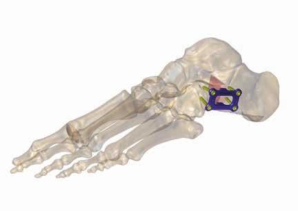
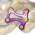
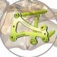
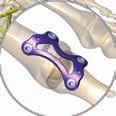
6 6 OPERATIVE TECHNIQUE Examples of RIVAL VIEW Plates applications LATERAL AXIAL
7 OPERATIVE TECHNIQUE 7 OPERATIVE TECHNIQUE Preoperative Planning The RIVAL VIEW Plating System is composed of a variety of plates and bone screws. Detailed preoperative planning is important for determining appropriate screw and plate sizes and location for the desired procedure(s) being performed. Surgical Technique The operative technique listed below is designed to provide general principles for the use of the RIVAL VIEW Plating System. Important indications and specific steps are also highlighted below. Exposure and Joint Preparation (OPTIONAL) 001-A Small Joint Distraction Forceps, 1.5mm Guide Wire 001-A Large Joint Distraction Forceps, 2.8mm Guide Wire (available upon request) Expose the implantation site with the appropriate surgical approach specific to the procedure(s) being performed. Table 2 identifies the recommended surgical approaches based on the indication. The surgical approach should facilitate adequate visualization of important anatomic structures and facilitate use of instrumentation and implant placement. TABLE 2: Recommended surgical approach by indication Indication/Plate Recommended Surgical approach MTP Dorsal approach Lapidus Dorsomedial approach Talonavicular Medial/Dorsomedial approach Calcaneocuboid Lateral approach Evans osteotomy Lateral approach For joint fusions, carefully prepare the surfaces of the joint to be fused. Remove joint cartilage and any fibrous tissue from within the joint. Using a drill and/or osteotome create multiple defects in the subchondral bone to stimulate bleeding. Care should be taken to maintain subchondral bone and, thereby, length. If necessary, use joint distraction forceps to distract the joint.

8 8 OPERATIVE TECHNIQUE SPECIFIC STEPS FOR MTP PLATES: Metatarsal Preparation 001-A Guide Wire 1.5mm, 4.0/4.5mm Bite Compression Screw CONE REAMERS 002-A Cone Reamer, 14mm, 002-A Cone Reamer, 16mm, 002-A Cone Reamer, 18mm, 002-A Cone Reamer, 20mm, Plantarflex the phalanx to expose the metatarsal head. Insert a Ø 1.5mm Guide Wire proximally through the center of the metatarsal head and advance it through medullary canal (Fig. 1). Fig. 1 Select the Cone Reamer that best matches the contour of the native metatarsal head. Using power, advance the Cone Reamer over the Ø 1.5mm Guide Wire (Fig. 2). Starting reaming action prior to advancing onto the bone can avoid excessive removal. Ensure that the surrounding soft tissues are adequately retracted to avoid injury. Retract reamer frequently to control resection of subchondral bone. Continue the reaming process, downsizing reamer sizes to match the metatarsal head as needed, until bleeding subchondral bone becomes visible to the joint surface. Take note of the last reamer size. NOTE: Check the progress of the reamers frequently to prevent excessive shortening of the metatarsal. Fig. 2 NOTE: Take care not to run the teeth of the reamer against the sesamoids.

9 OPERATIVE TECHNIQUE 9 Phalangeal Preparation 001-A Guide Wire 1.5mm, 4.0/4.5mm Bite Compression Screw CONE REAMERS 002-A Cup Reamer, 14mm, 002-A Cup Reamer, 16mm, 002-A Cup Reamer, 18mm, 002-A Cup Reamer, 20mm, Plantarflex the proximal phalanx, insert a Ø 1.5mm Guide Wire into the center of the joint surface and advance it into the diaphysis taking care not to penetrate the interphalangeal joint (Fig. 3). Fig. 3 Select the Cup Reamer that best matches the contour of the diameter of the phalangeal base. Using power, advance the Cup Reamer over the Ø 1.5mm Guide Wire (Fig. 4). Ensure that the surrounding soft tissues are adequately retracted to avoid injury. Retract the Cup Reamer frequently to control resection of subchondral bone. Continue the reaming process, increasing reamer sizes until the proximal phalanx is prepared with the same diameter utilized to prepare the metatarsal head. NOTE: Exposure to the articular surface can be maintained with general surgical instruments such as a curved McGlamry or Hohmann Retractor. Fig. 4

10 10 OPERATIVE TECHNIQUE SPECIFIC STEP FOR EVANS PLATES: Osteotomy Once adequate exposure is achieved, perform an osteotomy 1cm to 1.5cm posterior to the calcaneal - cuboid joint and just anterior to the subtalar joint. SPECIFIC STEP FOR LAPIDUS PLATES: If arthrodesis of the intercuneiform is necessary, that joint should be prepared and bone graft considered. Plate Selection and Temporary Fixation VIEW PLATES TRIALS 002-A View Trial, MTP Plate, Small 002-A View Trial, MTP Plate, Large 002-A View Trial, MTP Plate, Medium 002-A-01014L View Trial, Lapidus Plate, Small, 0mm Step, Left 002-A-01014R View Trial, Lapidus Plate, Small, 0mm Step, Right 002-A-01214L View Trial, Lapidus Plate, Small, 2mm Step, Left 002-A-01214R View Trial, Lapidus Plate, Small, 2mm Step, Right 002-A-02014L View Trial, Lapidus Plate, Large, 0mm Step, Left 002-A-02014R View Trial, Lapidus Plate, Large, 0mm Step, Right 002-A-02214L View Trial, Lapidus Plate, Large, 2mm Step, Left 002-A-02214R View Trial, Lapidus Plate, Large, 2mm Step, Right Provisionally fix the joint with K-wires and confirm the correct alignment with image intensifier. Use the RIVAL VIEW plate trials, found in the RIVAL Instrumentation, to evaluate and identify the appropriate plate size to fit individual patient anatomy. Once the best plate fit has been identified, open the corresponding sterile packed plate. If necessary, contour the selected plate by using plate bending irons available in the RIVAL Instrumentation (Fig. 5). 002-A View Trial, Tn Plate, Small 002-A View Trial, Tn Plate, Medium 002-A View Trial, Tn Plate, Large 002-A View Trial, Cc Plate, Small 002-A View Trial, Cc Plate, Medium 002-A View Trial, Cc Plate, Large 002-A View Trial, Evans Plate, 6mm Spacer 002-A View Trial, Evans Plate, 8mm Spacer 002-A View Trial, Evans Plate, 10mm Spacer 002-A View Trial, Evans Plate, 12mm Spacer PLATE BENDING IRONS 002-A Plate Bending Iron, Left 002-A Plate Bending Iron, Right Fig. 5 (optional) 002-A Plate Bending Joystick 002-A-2P003 Olive Wires (Kit Of 2)


11 OPERATIVE TECHNIQUE 11 SPECIFIC STEP FOR LAPIDUS PLATES: Lapidus Plate 5 th Tab Contouring 002-A Plate Bending Joystick The RIVAL VIEW Lapidus Plate has a 5 th tab that was designed for increased transverse stability. Prior to inserting screws contour the 5 th tab by using the plate bending joystick to optimize screw placement. Position the plate over the joint and provisionally stabilize using olive wires (Fig. 6). NOTE: RIVAL VIEW plate trials can be contoured by using plate bending irons and applied to the application site to identify the best fit. Fig. 6 WARNING: Excessive bending and re-bending of titanium plates can lead to plate failure and is not recommended. WARNING: Do not bend the plate using screw holes as it will damage the locking threads precluding their use. Preparing for Compression (only for Joint Compression Forceps) 001-A Joint Compression Forceps Using the joint compression forceps as guide, place two K-wires, one on each side of the joint to be compressed. Screw Selection All screw holes in the RIVAL VIEW Plating System accommodate both locking and non-locking screws. Select the appropriate screw diameter and type (See Table 1 pag. 4) based upon patient s bone quality and anatomy. Pre-drilling 002-A Standard Drill Bit, D 1.5mm X 125mm, 002-A Standard Drill Bit, D 2.0mm X 125mm, 002-A Drill Guide (Locking And Non-Locking) 002-A Locking Drill Sleeve Fig.7 WARNING: Do not use the locking drill sleeve as a bending iron for the plates as this may damage the threads and preclude the use of the locking mode. PRECAUTION: It is particularly important to frequently screen with an image intensifier during drilling. Use appropriate sterile packed drill bits with the appropriate drill guides found in the RIVAL Instrumentation (See Table 1 pag. 4) to prepare proximal or distal screw holes depending on the procedure being performed. Ensure complete drilling through both cortices (Fig. 7).
.")

12 12 OPERATIVE TECHNIQUE Screw length determination 002-A Depth Gauge With Hook Insert the depth gauge through the pilot hole and hook the far cortex. Press the barrel of the depth gauge to the surface of the plate to determine the screw length (Fig. 8). Image intensifier may be used to visualize the depth gauge and confirm correct screw position especially when screws are not placed perpendicular to the plate. Screw insertion 002-D-270XX Non-Locking Screws D 2.7mm 002-E-270XX Locking Screws D 2.7mm 002-D-320XX Non-Locking Screws D 3.2mm 002-E-320XX Locking Screws D 3.2mm 002-A Hex Screw Driver, For 2.0/2.7/3.2mm Screws, Fig. 8 Once the appropriate screw length is determined open the corresponding sterile packed screw. Use the hex screwdriver found in the RIVAL Instrumentation to advance the screw (Fig. 9) until it is fully seated and engaged in the plate. NOTE: Final screw tightening is not recommended until all desired screws have been inserted into the plate. WARNING: Screws must not be over-tightened during insertion. Excessive over-tightening will compromise the integrity of the screw head, resulting in possible screw stripping/breakage. Fig. 9 WARNING: Excessive tightening of a locking bone screw may to lead to stripping of the locking threads. In the event that a locking bone screw thread strips out, replace the locking screw with a non-locking screw. PRECAUTION: It is particularly important to frequently screen with an image intensifier during screw insertion.

13 OPERATIVE TECHNIQUE 13 Compression Once the plate has been fixed distally or proximally depending on the procedure being performed, remove olive wires at the opposite side in order to permit compression. Use joint compression forceps and/or interfragmentary screws to obtain compression. OPTION A: JOINT COMPRESSION FORCEPS 001-A Joint Compression Forceps Apply desired compression by using the joint compression forceps and maintain with locking feature on forceps. OPTION B: COMPRESSION SCREW INSERTION For procedures where an interfragmentary screw is recommended (Table 3), reference the RIVAL BITE Headed Cannulated and Headless Compression Screw Operative Technique for step by step instructions for compression screw insertion. NOTE: When placing interfragmentary compression screws make sure to avoid interference with the plate and existing and proposed screws. TABLE 3: Interfragmentary RIVAL BITE Screw Recommendations Indication/Procedure Recommended Screw Size MTP 3.0, 3.5 or 4.0mm Lapidus 3.5 or 4.0mm Calcaneal-cuboid 4.0, 4.5 or 6.5mm Talonavicular 4.0, 4.5 or 6.5mm Completion of screw insertion Repeat drill, measuring and placement of screws in other holes as required (Fig. 10) to complete plate fixation. NOTE: Remember to use the appropriate drill size for the desired screw diameter. Remove joint compression forceps and/or provisional fixation. Fig. 10
 or middle cuneiform (Fig. 12) to minimize any instability at the intercuneiform joint.")

14 14 OPERATIVE TECHNIQUE SPECIFIC STEP FOR LAPIDUS PLATE Insertion of the screw in the 5 th tab After placing all four perimeter screws, secure the 5 th tab. It is possible to place a screw in the second metatarsal (Fig. 11) or middle cuneiform (Fig. 12) to minimize any instability at the intercuneiform joint. It is recommended to use a non-locking 3.2mm bone screws placed in lag mode. Fig. 11 Fig. 12 Final screw tightening When all desired screws have been inserted into the plate, perform final manual tightening with consideration. Final fluoroscopic control Use image intensifier to control final plate and screws position.

. Fig.")
15 OPERATIVE TECHNIQUE 15 Plate and Screw Removal 002-A Hex Screw Driver, For 2.0/2.7/3.2mm Screws, Quick Connect 003-A Soft Tissue Elevator If the plate and screws need to be removed, perform appropriate surgical incisions to adequately expose the implantation site. If necessary, remove overgrown bone to expose entire screw heads. Use the hex screwdriver found in the RIVAL Instrumentation to remove each screw from the plate (Fig. 13). Fig. 13 Use a soft tissue elevator or other general surgical grasping instrument to lift off the plate from the bone (Fig. 14). Fig. 14
16 Electronic Instructions for use available at the website Electronic Instructions for use - Minimum requirements for consultation: Internet connection (56 kbps) Device capable to visualize PDF (ISO/IEC ) files Disk space: 50Mbites Free paper copy can be requested to customer service (delivery within 7 days): tel , fax , customerservice@orthofix.it Distributed by: Manufactured by: ORTHOFIX Srl Via Delle Nazioni 9, Bussolengo (Verona), Italy Telephone , Fax Instructions for Use: See actual package insert for Instructions for Use. RI-1703-OPT-E0 D 08/17 Caution: Federal law (USA) restricts this device to sale by or on the order of a physician. Proper surgical procedure is the responsibility of the medical professional. Operative techniques are furnished as an informative guideline. Each surgeon must evaluate the appropriateness of a technique based on his or her personal medical credentials and experience. Please refer to the Instructions for Use supplied with the product for specific information on indications for use, contraindications, warnings, precautions, adverse reactions and sterilization.
OPERATIVE TECHNIQUE RIVAL REDUCE FRACTURE PLATING SYSTEM. foot & ankle trauma procedures
 OPERATIVE TECHNIQUE RIVAL REDUCE FRACTURE PLATING SYSTEM foot & ankle trauma procedures INTRODUCTION 3 SYSTEM DESCRIPTION 3 TECHNICAL DETAILS 4 SALES AND MARKETING CONFIGURATION 5 OPERATIVE TECHNIQUE 7
OPERATIVE TECHNIQUE RIVAL BITE HEADED CANNULATED AND HEADLESS COMPRESSION SCREWS. foot & ankle applications
 OPERATIVE TECHNIQUE RIVAL BITE HEADED CANNULATED AND HEADLESS COMPRESSION SCREWS foot & ankle applications INTRODUCTION 3 SYSTEM DESCRIPTION 3 TECHNICAL DETAILS 4 SALES AND MARKETING CONFIGURATION 6 OPERATIVE
MTP Fusion Surgical Technique
 MTP Fusion Surgical Technique Patent and Patent Pending CAUTION: Federal Law (USA) restricts this device to sale by or on the order of a physician. INDICATIONS FOR USE The Omni Foot Plating System is intended
DART-FIRE. Small Screw System SURGICAL TECHNIQUE
 DART-FIRE Small Screw System SURGICAL TECHNIQUE DART-FIRE Small Screw System Surgical Technique Contents Chapter 1 4 Chapter 2 6 Chapter 3 7 Appendix 1 10 Appendix 2 12 Introduction Intended Use DART-FIRE
Surgical Technique. Customer Service:
 Patent Pending CAUTION: Federal Law (USA) restricts this device to sale by or on the order of a physician. Notes This page is blank INDICATIONS FOR USE The Extremity Medical Hallu X Intramedullary Fusion
Technique Guide MTP Arthrodesis System
 Technique Guide MTP Arthrodesis System The CheckMATE MTP Arthrodesis System features low-profile, anatomically pre-contoured Bone Plates with either a combination of locking and non-locking holes or all-locking
DART-FIRE. Small Screw System SURGICAL TECHNIQUE
 DART-FIRE Small Screw System SURGICAL TECHNIQUE DART-FIRE Small Screw System SURGICAL TECHNIQUE Contents Chapter 1 4 Chapter 2 6 Appendix 1 9 Appendix 2 11 Introduction DART-FIRE Small Screw System Surgical
Integra. Capture Screw System SURGICAL TECHNIQUE
 Integra Capture Screw System SURGICAL TECHNIQUE Table of Contents Indications... 2 Contraindications... 2 System Description... 2 System Features... 2 Cannulated Low-Profile Screws (AC-Series) Overview...
DART-FIRE. Small Screw System SURGIC A L T ECHNIQUE
 DART-FIRE Small Screw System SURGIC A L T ECHNIQUE Contents Headline Headline PREFACE Chapter 1 4 Chapter 2 6 Chapter 3 7 Appendix A 10 Appendix B 12 Introduction Intended Use DART-FIRE Small Screw System
MTP Set SURGICAL TECHNIQUE
 MINI MAXLOCK EXTREME MTP Set SURGICAL TECHNIQUE Contents Table of Contents Key Design Features 3 Surgical Technique Standard MTP Plate 4 MTP Plate with POCKETLOCK Technology 10 Implants and Instruments
MEDIALMAX System SURGICAL TECHNIQUE
 MAXLOCK EXTREME MEDIALMAX System SURGICAL TECHNIQUE Contents The MEDIALMAX Advantage Design Feature Various flex options POCKETLOCK Technology Anatomic design Advantage Provides the surgeon with multiple
ISO Plate SURGICAL TECHNIQUE
 MINI MAXLOCK EXTREME ISO Plate SURGICAL TECHNIQUE Contents Table of Contents Key Design Features 2 Surgical Technique 3 Implants and Instruments 8 Key Design Features The MINI MAXLOCK EXTREME ISO (Intraosseous
Treace Medical Concepts Plating System
 Treace Medical Concepts Plating System Multiplanar Fixation System Surgical Technique Lapidus and 1 st MTP Fusion Lapidus Fusion Surgical Approach 1. Perform a longitudinal incision dorsally over the 1
Technique Guide. 2.4/2.7 mm Locking Tarsal Plates. Talus Plate, Navicular Plate and Cuboid Plate.
 Technique Guide 2.4/2.7 mm Locking Tarsal Plates. Talus Plate, Navicular Plate and Cuboid Plate. Table of Contents Introduction 2.4/2.7 mm Locking Tarsal Plates 2 AO Principles 4 Indications 5 Clinical
CHARLOTTE CLAW Plate Compression Locking Arthrodesis by Wright SURGICAL TECHNIQUE
 CHARLOTTE CLAW Plate Compression Locking Arthrodesis by Wright SURGICAL TECHNIQUE Contents Chapter 1 1 Chapter 2 2 2 2 3 4 5 6 Appendix A 7 Preoperative Planning Surgical Technique Calcaneal Cuboid Arthrodesis
VLP FOOT Variable Angle Locked Plating System
 Surgical Technique VLP FOOT Variable Angle Locked Plating System Surgical Technique Table of Contents Product overview Implant selection...2 Introduction...3 System overview...4 Indications...4 Design
MaxTorque. surgical technique. Cannulated Screw System. Foot & Ankle. OrthoHelix Technology
 MaxTorque Cannulated Screw System OrthoHelix Technology surgical technique Foot & Ankle 2 M A X T O R Q U E C A N N U L A T E D S C R E W S Y S T E M Table of Contents Advantages 3 Indications 4 Contraindications
Integra. Stainless Headed Compression Screw System SURGICAL TECHNIQUE
 Integra Stainless Headed Compression Screw System SURGICAL TECHNIQUE Table of Contents Design Rationale...2 Indications...2 Contraindications...2 Surgical Technique Step 1: Inserting Guide Wire... 3 Step
ORTHOLINK. 2 - Hole Wedge Osteotomy Plate SURGICAL TECHNIQUE
 MAXLOCK EXTREME ORTHOLINK 2 - Hole Wedge Osteotomy Plate SURGICAL TECHNIQUE Contents Key Design Features 3 Surgical Technique 4 Implants and Instruments 7 Proper surgical procedures and techniques are
VariAx Foot Locking Plate System
 VariAx Foot Locking Plate System Operative Technique Trauma and Deformity Correction Polyaxial Locking Technology Comprehensive Calcaneal Fracture Plates Table of Contents 1. Introduction 3 2. Overview
BioDrive Micro Screw System
 At Biomet, engineering excellence is our heritage and our passion. For over 25 years, through various divisions worldwide, we have applied the most advanced engineering and manufacturing technology to
Small Plate and Screw System SURGICAL TECHNIQUE
 MINI MAXLOCK EXTREME Small Plate and Screw System SURGICAL TECHNIQUE Contents Key Design Features 2 Surgical Technique 3 Implants and Instruments 9 Proper surgical procedures and techniques are the responsibility
Integra SURGICAL TECHNIQUE. HALLU -Fix and HALLU -Lock MTP Arthrodesis Systems. HALLU Lock C plate. HALLU -C plate. HALLU -S plate. HALLU Lock S plate
 EN Integra HALLU -Fix and HALLU -Lock MTP Arthrodesis Systems SURGICAL TECHNIQUE HALLU -C plate HALLU Lock C plate HALLU -S plate HALLU Lock S plate Products for sale in Europe, Middle-East and Africa
Integra. HALLU -Lock M.T.P. Arthrodesis System SURGICAL TECHNIQUE
 Integra HALLU -Lock M.T.P. Arthrodesis System SURGICAL TECHNIQUE Table of Contents... 02 Indications... 02 Contraindications... 02 Surgical Technique... 03 Step 1: Incision... 03 Step 2: Preparation of
VariAx. Foot & Ankle. Foot Locking Plate System
 VariAx Foot Locking Plate System Operative Technique Foot & Ankle Trauma and Deformity Correction Polyaxial Locking Technology Comprehensive Calcaneal Fracture Plates VariAx 2 Plates VariAx Foot Locking
Integra. Tibio Talo Calcaneus Plate SURGICAL TECHNIQUE
 Integra Tibio Talo Calcaneus Plate SURGICAL TECHNIQUE Table of Contents Indications...02 Contraindications...02 Description...02 Surgical Technique...03 Step 1: Articular Surfaces Preparation...03 Step
Technique Guide. Variable Angle LCP 1 st MTP Fusion Plates 2.4/2.7. Part of the Variable Angle LCP Forefoot / Midfoot System 2.4 / 2.7.
 Technique Guide Variable Angle LCP 1 st MTP Fusion Plates 2.4/2.7. Part of the Variable Angle LCP Forefoot / Midfoot System 2.4 / 2.7. Table of Contents Introduction Variable Angle LCP 1 st MTP Fusion
Mecron Cannulated Screws
 Surgical Technique and Ordering Information 2 Table of contents Description... 4 Indications for use... 4 Contraindications... 4 State-of-the-art design features... 5 Surgical Technique... 6 Surgery Steps
CHARLOTTE. Multi-Use Compression Screw
 CHARLOTTE Multi-Use Compression Screw CHARLOTTE multi-use compression screw surgical technique SURGICAL ADVISORS ROBERT ANDERSON, MD BRUCE COHEN, MD W. HODGES DAVIS, MD Proper surgical procedures and techniques
LCP Pilon Plate 2.7/3.5
 Surgical Technique LCP Locking Compression Plate Original Instruments and Implants of the Association for the Study of Internal Fixation AO/ASIF Table of contents Indications 3 Implants 4 Instruments 5
HCS 1.5. The countersinkable compression screw.
 HCS 1.5. The countersinkable compression screw. Surgical Technique This publication is not intended for distribution in the USA. Instruments and implants approved by the AO Foundation. Table of Contents
VECTRA SURGICAL TECHNIQUE. Anterior cervical plate system. This publication is not intended for distribution in the USA.
 VECTRA Anterior cervical plate system This publication is not intended for distribution in the USA. SURGICAL TECHNIQUE Image intensifier control This description alone does not provide sufficient background
Distal Fibula Plate SURGICAL TECHNIQUE
 MAXLOCK EXTREME Distal Fibula Plate SURGICAL TECHNIQUE Contents Key Design Features 3 Surgical Technique 4 Implants and Instruments 8 Proper surgical procedures and techniques are the responsibility of
Technique Guide. LCP Pilon Plate 2.7/3.5
 Technique Guide LCP Pilon Plate 2.7/3.5 LCP Pilon Plate 2.7/3.5 Table of contents Indications 3 Implants 4 Instruments 5 Surgical technique 6 Implant removal 12 Image intensifier control Warning This
5th Metatarsal Fracture System Surgical Technique
 5th Metatarsal Fracture System Surgical Technique 5th Metatarsal Fracture System 5th Metatarsal Fracture System The 5th Metatarsal Fracture System (AR-8956S) is a uniquely designed screw and plate system
Digital Compression Screw
 Digital Compression Screw Surgical Technique Contents Product The BioPro Digital Compression Screw is a stainless steel lag screw designed for digital fusions. Table of contents Indications & Contraindications
TORNIER MAXLOCK EXTREME. Clavicle Plating System SURGICAL TECHNIQUE
 TORNIER MAXLOCK EXTREME Clavicle Plating System SURGICAL TECHNIQUE 2 Table of Contents: Key Design Features...4 Surgical Technique...5 Implants & Instruments...9 3 Key Design Features There are 7 anatomically
2.4 mm and 3.0 mm Headless Compression Screws
 For Fixation of Small Bones and Small Bone Fragments 2.4 mm and 3.0 mm Headless s Surgical Technique Table of Contents Introduction 2.4 mm and 3.0 mm Headless 2 Technique Overview 4 AO Principles 5 Indications
HCS 2.4/3.0. The countersinkable compression screw.
 Technique Guide HCS 2.4/3.0. The countersinkable compression screw. Table of Contents Introduction Features and Benefits 2 Functional Principle 3 Indications 4 Surgical Technique Hand Scaphoid 5 Foot
Table of Contents 2-6. Introduction. Indications Surgical Technique. Ordering Information 15-24
 Table of Contents Introduction Product information ExtremiFix Midsize Large Screw Offering Headless Screw Characteristics Design Features & Benefits Instrumentation Technical Details Calibrated Drill Bits
Titanium Modular Hand System. For fractures, replantations and reconstruction of the hand.
 Titanium Modular Hand System. For fractures, replantations and reconstruction of the hand. Plates precontoured for anatomic fit Instruments colorcoded for easy recognition Modules for 1.0 mm to 2.4 mm
Universal Humeral Nail
 990210009 INDEX Indications Preoperative Planning Patient Position Surgical Technique - Step 1 Open Humerus - Step 2 Calibrate The Nail - Step 3 Insert Nail - Step 4 Proximal Locking - Step 5 Assemble
Instructions for Use. LCP Locking Compression Plate. Combine without Compromise.
 Instructions for Use LCP Locking Compression Plate. Combine without Compromise. Table of Contents LCP: Combine without Compromise 2 AO ASIF Principles of Osteosynthesis 4 Indications and Contraindications
Surgical Technique. Acutrak Headless Compression Screw System
 Surgical Technique Acutrak Headless Compression Screw System Acumed is a global leader of innovative orthopaedic and medical solutions. We are dedicated to developing products, service methods, and approaches
Variable Angle LCP Forefoot/Midfoot System 2.4/2.7. Procedure specific plates for osteotomies, arthrodeses and fractures of the foot.
 Instruction for Use Variable Angle LCP Forefoot/Midfoot System 2.4/2.7. Procedure specific plates for osteotomies, arthrodeses and fractures of the foot. Table of Contents Introduction VA-LCP Forefoot/Midfoot
LCP Pilon Plate 2.7/3.5
 LCP Pilon Plate 2.7/3.5 Surgical Technique This publication is not intended for distribution in the USA. Instruments and implants approved by the AO Foundation. Table of contents Indications 2 Implants
VECTRA. SURGICAL TECHNIQUE. Anterior cervical plate system. This publication is not intended for distribution in the USA.
 VECTRA. Anterior cervical plate system. This publication is not intended for distribution in the USA. SURGICAL TECHNIQUE Contents Indications and contraindications Implants Vario Case Instruments Surgical
Fibula Plating System
 ANATOMIC LOCKED PLATING SYSTEM Fibula Plating System Securing optimal fixation through versatile locked and compression plating technology Contents Surgeon Design Team 2 Introduction 3 Anatomic Fibula
DISTAL RADIUS PLATES 3.5 mm / ANGULARLY STABLE. Distal radius plates 3,5 mm / angularly stable. Locking bone screws. Cortical bone screw
 SURGICAL NÁSTROJE TECHNIQUE PRO ARTROSKOPII DISTAL INSTRUMENTS RADIUS PLATES FOR ARTHROSCOPY 3.5 mm / ANGULARLY STABLE Distal radius plates 3.5 mm / angularly stable Indication The plates are used for
Variable Angle LCP Tarsal Plates 2.4/2.7. Navicular Plate and Cuboid Plates.
 Variable Angle LCP Tarsal Plates 2.4/2.7. Navicular Plate and Cuboid Plates. Surgical Technique This publication is not intended for distribution in the USA. Instruments and implants approved by the AO
Distal Medial Tibia Plate Surgical Technique
 Locking Compression Technology by aap 1 Disclaimer This surgical technique is exclusively intended for medical professionals, especially physicians, and therefore may not be regarded as a source of information
Surgical Technique 1
 Surgical Technique 1 D-RAD SMART PACK Single-Use Volar Distal Radius Plating System Surgical Technique Table of Contents Indications... 3 Contraindications... 3 D-RAD SMART PACK product overview... 4 Instrumentation...
Headless Compression and Twist-Off Screws
 Headless Compression and Twist-Off Screws The Next Generation Barouk Screw Surgical Technique Table of Contents System Introduction... 2 Headless Compression Screw... 4 Incision... 5 Lateral Release...
Technique Guide. Quadrilateral Surface Plates 3.5. Part of the Low Profile Pelvic System 3.5.
 Technique Guide Quadrilateral Surface Plates 3.5. Part of the Low Profile Pelvic System 3.5. Table of Contents Introduction Quadrilateral Surface Plates 3.5 2 AO Principles 4 Indications 5 Surgical Technique
3.5 mm Cannulated Screw Technique Guide
 3.5 mm Cannulated Screw Technique Guide An Integral Part of the SYNTHES Cannulated Screw System Original Instruments and Implants of the Association for the Study of Internal Fixation AO ASIF The 3.5 mm
OsteoBridge IKA Intramedullary Knee Arthrodesis Fixation System. From the «BioBall Company» OsteoBridge Family
 From the «BioBall Company» OsteoBridge Family OsteoBridge IKA Intramedullary Knee Arthrodesis Fixation System The modular system for the fixation of the knee joint 01. OsteoBridge IKA The OsteoBridge IKA
Expert HAN. Expert Hindfoot Arthrodesis Nail.
 Expert HAN. Expert Hindfoot Arthrodesis Nail. Technique Guide Expert Nailing System Table of Contents Introduction Expert Hindfoot Arthrodesis Nail 2 AO Principles 4 Indications 5 Surgical Technique Preoperative
Technique Guide. 7.0 mm Cannulated Screws. Part of the Synthes Cannulated Screw System.
 Technique Guide 7.0 mm Cannulated Screws. Part of the Synthes Cannulated Screw System. Table of Contents Introduction 7.0 mm Cannulated Screws 2 AO Principles 3 Indications 4 Surgical Technique Surgical
2.4 mm Cannulated Screw. An integral part of the Synthes Cannulated Screw System (CSS).
.") 2.4 mm Cannulated Screw. An integral part of the Synthes Cannulated Screw System (CSS). Surgical Technique This publication is not intended f distribution in the USA. and implants approved by the AO Foundation.
2.4 mm Cannulated Screw. An integral part of the Synthes Cannulated Screw System (CSS). Surgical Technique This publication is not intended f distribution in the USA. and implants approved by the AO Foundation.
The Percutaneous Reduction Forceps Technique Guide
 The Percutaneous Reduction Forceps Technique Guide Indications + Product Overview Introduction The Percutaneous Reduction Forceps The Percutaneous Reduction Forceps facilitate standard technique for fixation
1.5 MM LCP SYSTEM. For treatment of fractures and arthrodeses of canines and felines SURGICAL TECHNIQUE
 1.5 MM LCP SYSTEM For treatment of fractures and arthrodeses of canines and felines SURGICAL TECHNIQUE TABLE OF CONTENTS INTRODUCTION 1.5 mm LCP System 2 AO Principles 4 SURGICAL TECHNIQUE Reduce Fracture
Instruments for Removing DePuy Synthes Screws. Screw Removal Set
 Instruments for Removing DePuy Synthes Screws Screw Removal Set Surgical Technique Table of Contents Introduction Screw Removal Set 2 Surgical Technique Preoperative Planning and Preparation 6 Removal
FOOTMOTION FOREFOOT. INNOVATION means MOTION. Self-drilling and self-tapping screws Optimal compression Innovative ergonomic instruments
 INNOVATION means MOTION FOOTMOTION FOREFOOT SCREWS / PERCUTANEOUS REAMERS / STA PLES Self-drilling and self-tapping screws Optimal compression Innovative ergonomic instruments FO OTMOTION A COMPREHENSIVE
Technique Guide. Modular Sternal Cable System. Flexibility and strength in sternal closure and repair.
 Technique Guide Modular Sternal Cable System. Flexibility and strength in sternal closure and repair. Table of Contents Introduction Overview 2 Indications and Contraindications 3 Surgical Technique A.
Proximal Humerus Plate 3.5 Surgical Technique
 Locking Compression Technology by aap 1 Disclaimer This surgical technique is exclusively intended for medical professionals, especially physicians, and therefore may not be regarded as a source of information
Variable Angle LCP Mesh Plate 2.4/2.7. Part of the Variable Angle LCP Forefoot/Midfoot System 2.4/2.7.
 Variable Angle LCP Mesh Plate 2.4/2.7. Part of the Variable Angle LCP Forefoot/Midfoot System 2.4/2.7. Surgical Technique This publication is not intended for distribution in the USA. Instruments and implants
Technique Guide. Variable Angle LCP Opening Wedge Plates 2.4/2.7. Part of the Variable Angle LCP Forefoot / Midfoot System 2.4 / 2.7.
 Technique Guide Variable Angle LCP Opening Wedge Plates 2.4/2.7. Part of the Variable Angle LCP Forefoot / Midfoot System 2.4 / 2.7. Table of Contents Introduction Variable Angle LCP Opening Wedge Plates
MatrixMANDIBLE Preformed Reconstruction Plates. Preshaped to the mandibular anatomy.
 MatrixMANDIBLE Preformed Reconstruction Plates. Preshaped to the mandibular anatomy. Technique Guide CMF Matrix Table of Contents Introduction MatrixMANDIBLE Preformed Reconstruction Plates 2 AO Principles
Technique Guide. 4.5 mm Cannulated Screws. Part of the Synthes Cannulated Screw System.
 Technique Guide 4.5 mm Cannulated Screws. Part of the Synthes Cannulated Screw System. TableofContents Introduction 4.5 mm Cannulated Screws 2 AO Principles 3 Indications 4 Surgical Technique Surgical
Distal Radius System 2.5
 SURGICAL TECHNIQUE STEP BY STEP Distal Radius System 2.5 APTUS Wrist 2 Distal Radius System 2.5 Contents 3 Introduction 3 Product Materials 3 Indications 3 Contraindications 3 Color Coding 3 Possible Combination
7.0 mm Cannulated Screws
 Part of the DePuy Synthes Cannulated Screw System 7.0 mm Cannulated Screws Surgical Technique Table of Contents Introduction 7.0 mm Cannulated Screws 2 AO Principles 3 Indications 4 Surgical Technique
CETRA ANTERIOR CERVICAL PLATE
 CETRA TM ANTERIOR CERVICAL PLATE The CETRA Anterior Cervical Plate System offers a low profile titanium alloy plate with an intuitive locking mechanism, large graft windows, a high degree of screw angulation
VARIABLE ANGLE LOCKING HAND SYSTEM
 VARIABLE ANGLE LOCKING HAND SYSTEM For fragment-specific fracture fixation with variable angle locking and locking technology Instruments and implants approved by the AO Foundation. This publication is
Calcaneus StepPlate. Surgical Technique. Calcaneus StepPlate
 Calcaneus StepPlate Surgical Technique Calcaneus StepPlate Medializing Calcaneal Osteotomy (MCO) with Calcaneus StepPlate 1 2 Perform an incision on the lateral side of the calcaneus. An L -shaped incision
Orthopedic Bone Nail System Universal Humeral Nail
 Orthopedic Bone Nail System Universal Humeral Nail Surgical Technique Manual Note: The surgical procedures should be performed under the guidance of qualified skilled orthopedic surgeons, and this surgical
Surgical Technique 1
 Surgical Technique 1 CUP AND CONE REAMERS Surgical Technique Table of Contents Product Overview Introduction...2 Design features and benefits...2 Surgical Technique Preparation...3 Ream metatarsal...3
VariAx Fibula Locking Plate System
 VariAx Fibula Locking Plate System Operative Technique Distal Fibula Fracture Repair Polyaxial Locking Technology Low Profile Design 1 Contributing Surgeon: Bradley R. Merk, MD Associate Professor of Orthopaedic
VariAxFibula. Fibula Fractures. Locking Plate System. Operative Technique
 Foot and Ankle VariAxFibula Locking Plate System Operative Technique Fibula Fractures Distal Fibula Fracture Repair Polyaxial Locking Technology Low Profile Design VariAx Fibula Locking Plate System Contributing
WRIST SYSTEM. ARIX Volar Distal Radius Locking Plate System
 WRIST SYSTEM A Contents 3 4 7 14 15 16 19 21 Indications Product Overview Features & Benefits Ordering Information - Screws -2.5mm Self-Tapping Cortical Screws (Non-Locking) -2.5mm Self-Tapping Locking
4.5/6.7 mm Low Profile Screw System Surgical Technique. 4.5/6.7 mm Low Profile Screw System
 4.5/6.7 mm Low Profile Screw System Surgical Technique 4.5/6.7 mm Low Profile Screw System This is a Foot Screw Not a Hip Screw Designed in conjunction with foot and ankle surgeons, the Arthrex Cannulated
Small Fragment Locking Compression Plate (LCP ) System Stainless Steel and Titanium TECHNIQUE GUIDE
 System Stainless Steel and Titanium TECHNIQUE GUIDE") Small Fragment Locking Compression Plate (LCP ) System Stainless Steel and Titanium TECHNIQUE GUIDE R Original Instruments and Implants of the Association for the Study of Internal Fixation AO ASIF Introduction
Small Fragment Locking Compression Plate (LCP ) System Stainless Steel and Titanium TECHNIQUE GUIDE R Original Instruments and Implants of the Association for the Study of Internal Fixation AO ASIF Introduction
Back to health. Back to work. Back to life.
 TECHNIQUE Back to health. Back to work. Back to life. U PLUS 90 INSTRUMENTATION OVERVIEW W&H IMPLANTMED POWER UNIT OVERVIEW Low-profile Primary Guides Compresses the U-clip to match rib thickness Clamps
6.5 mm and 7.3 mm Cannulated Screws Technique Guide
 6.5 mm and 7.3 mm Cannulated Screws Technique Guide An Integral Part of the SYNTHES Cannulated Screw System Original Instruments and Implants of the Association for the Study of Internal Fixation AO ASIF
Fixation screw ENGLISH
 Fixation screw ENGLISH CONCEPT The QWIX fixation screws were designed for extremity fixation and provide speed and precision for challenging surgical situations. The QWIX screw s unique design allows:
surgical technique addendum
 s h o u l d e r Solutions by Tornier Aequalis reversed II shoulder system surgical technique addendum Aequalis reversed II threaded post baseplate surgical technique addendum s u r g i c a l t e c h n
LCP Pilon Plate 2.7/3.5. Surgical Technique
 LCP Pilon Plate 2.7/3.5 Surgical Technique Image intensifier control This description alone does not provide sufficient background for direct use of DePuy Synthes products. Instruction by a surgeon experienced
Zimmer Natural Nail System
 Zimmer Natural Nail System Cephalomedullary Nail Surgical Technique Compact Case- Short Nails Only SMALL Zimmer Natural Nail System Cephalomedullary Nail Technique - Small 1 Zimmer Natural Nail System
Anterior Cervical Plate SURGICAL TECHNIQUE GUIDE. Surgeon Driven Innovation
 Anterior Cervical Plate SURGICAL TECHNIQUE GUIDE Surgeon Driven Innovation 1 The Snowmass Anterior Cervical Plate System is intended for the surgical treatment and correction of traumatic and pathologic
Ankle Fracture System. Surgical Technique STRENGTH FROM WITHIN
 Ankle Fracture System Surgical Technique STRENGTH FROM WITHIN Ankle Fracture System The Sonoma FibuLock nail is the first intramedullary device that has the same indications as plates and delivers anatomic
Technique Guide. Synapse System. An enhanced set of instruments and implants for posterior stabilization of the cervical and upper thoracic spine.
 Technique Guide Synapse System. An enhanced set of instruments and implants for posterior stabilization of the cervical and upper thoracic spine. Table of Contents Introduction Synapse System 2 AO Principles
Technique Guide. Occipito-Cervical Fusion System. Implants and instruments designed to optimize fixation to the occiput.
 Technique Guide Occipito-Cervical Fusion System. Implants and instruments designed to optimize fixation to the occiput. Table of Contents Introduction Overview 2 AO ASIF Principles 4 Indications and Contraindications
Humeral Nail System Procedural Steps.
 Humeral Nail System Procedural Steps www.carbo-fix.com Table of Contents Introduction..3 Instrumentation Set... 8 Procedural Steps: Humeral Nail.........10 Procedural Steps: Proximal Humeral Nail.....13
ACLP Anterior Cervical Locking Plate System TECHNIQUE GUIDE
 ACLP Anterior Cervical Locking Plate System TECHNIQUE GUIDE Instruments and implants approved by the AO Foundation ACLP Anterior Cervical Locking Plate System The ACLP System is designed to reduce the
TwinFix Surgical Protocol. 3.2mm Cannulated Compression Screw System
 TwinFix Surgical Protocol Compression Screw System TwinFix Compression Screw System Indications for Use: The Stryker TwinFix Interfragmentary Compression Screw System is intended to be used for fractures
Aesculap Spine S 4 Spinal System. Instrumentation Guide
 Aesculap Spine S 4 Spinal System Instrumentation Guide S 4 Spinal System S 4 From initial conception, the S 4 Spinal System was developed to meet the spine surgeon s need for an extremely low profile and
SpeedTip CCS 5.0, 7.0
 SURGICAL TECHNIQUE STEP BY STEP SpeedTip CCS 5.0, 7.0 Cannulated Compression Screws APTUS 2 SpeedTip CCS 5.0, 7.0 Cannulated Compression Screws Contents 3 Introduction Product Materials Indications Contraindications
Zimmer Natural Nail System
 Zimmer Natural Nail System Cephalomedullary Nail Surgical Technique Compact Case - Short Nails Only STANDARD Zimmer Natural Nail System Cephalomedullary Nail Surgical Technique - Standard 1 Zimmer Natural
VARIABLE ANGLE LOCKING HAND SYSTEM
 VARIABLE ANGLE LOCKING HAND SYSTEM For fragment-specific fracture fixation with variable angle locking and locking technology SURGICAL TECHNIQUE TABLE OF CONTENTS INTRODUCTION Variable Angle Locking Hand
Operative Technique Distal Fibula Fracture Repair Polyaxial Locking Technology Low Profile Design
 VariAx Fibula Locking Plate System Operative Technique Distal Fibula Fracture Repair Polyaxial Locking Technology Low Profile Design Contributing Surgeon: Bradley R. Merk, MD Associate Professor of Orthopaedic
Bio-Compression. Arthrex. Screw System
 Bio-Compression Arthrex Screw System Ordering Information 3 mm Bio-Compression Screw Instrumentation Set (AR-5025S) includes: Bio-Compression Screw Driver, noncannulated, 2.7 mm AR-5025DB Small Handle