Fibula Plating System
|
|
|
- Marilyn Short
- 5 years ago
- Views:
Transcription

1 ANATOMIC LOCKED PLATING SYSTEM Fibula Plating System Securing optimal fixation through versatile locked and compression plating technology
2
3 Contents Surgeon Design Team 2 Introduction 3 Anatomic Fibula Locking Plate 10 Fibula Composite Locking Plate 11 Screw Specifications 12 Plates 13 Anatomic Plate Bending 14 Application of the Anatomic Plate 15 Composite Plate Bending 16 Application of the Composite Plate 17 Screw Insertion 18 Ordering Information 25 1
4 Surgeon Design Team Roy Sanders, M.D. Chief, Department of Orthopaedics, Tampa General Hospital, Director, Orthopaedic Trauma Services, Florida Orthopaedic Institute Tampa, Florida George Haidukewych, M.D. Orthopaedic Trauma Service, Florida Orthopaedic Institute, Tampa General Hospital, Tampa, Florida David M. Huebner, M.D. Director of Orthopaedic Trauma, Good Samaritan Hospital, Kearney, Nebraska Michael Wich, M.D. Deputy Head, Department of Trauma and Orthopaedic Surgery, Unfallkrankenhaus Berlin Berlin, Germany 2
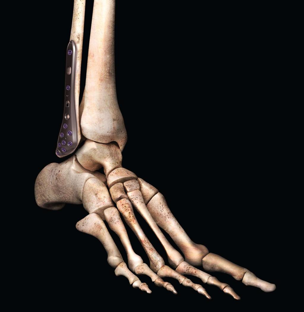
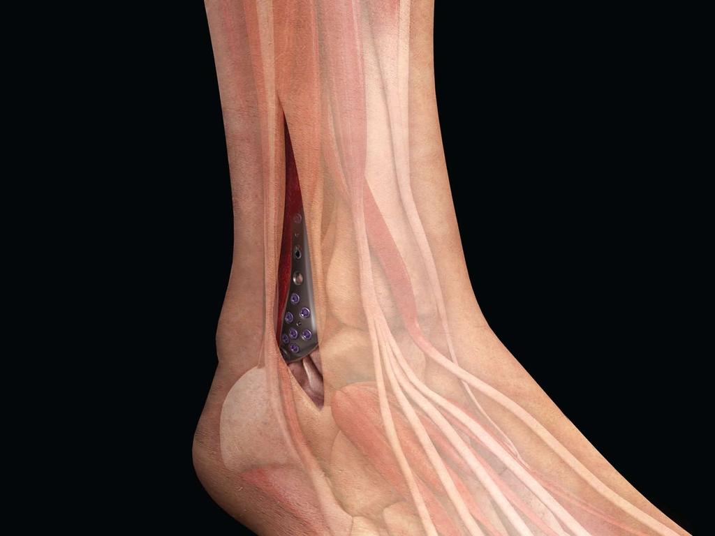
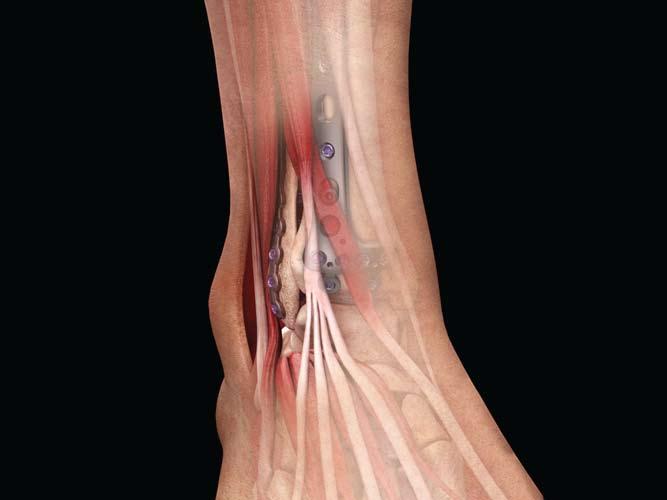
5 Introduction The A.L.P.S. Fibula plates represent the next generation in anatomic plate design. It combines the benefits of low profile titanium plate metallurgy with the advantages of multi-planar locked screw technology. These features allow the formation of a three dimensional matrix of fixed and variable angle screws to create a true subchondral scaffold that can provide fixation in comminuted fractures or osteoporotic bone. The A.L.P.S. Fibula plates feature TiMAX low profile, anatomically contoured implants. In distal fibula surgery where soft tissue coverage is at risk, these low profile plates are designed to minimize discomfort and soft tissue irritation matching the anatomy of the distal fibula, while still having the required strength. These plates feature F.A.S.T. Guide and Flexible Plating Technology to facilitate surgical procedures and save time in the operating room. F.A.S.T. Guide inserts allow for accurate drilling and placement of screws. F.A.S.T. Guide inserts are preloaded and do not require intraoperative assembly, resulting in significant time savings. These plates can also be customized intra-operatively to achieve an optimum anatomic fit. Additionally, the A.L.P.S. Fibula plates allow the use of locking, variable angle, and standard screws. This hybrid fixation concept allows the surgeon to stabilize the fracture either by the use of lag screw techniques through the plate, or by compression plating techniques. Locking screws serve to provide stability to comminuted, unstable metaphyseal fractures or in osteopenic bone. Intended use: Fixation of fractures, osteotomies and non-unions of the fibula, malleolus, distal tibia, metatarsals, scapula, clavicle, distal humerus, olecranon, ulna, radius, and metacarpals, particularly in osteopenic bone. 3
6
7 Low Profile Fibula Plates Anatomic fibula plate is pre-contoured to mimic the anatomy of the distal fibula for optimum bone conformance Composite locking plate combines the features of a locking compression plate and flexible plating technology Low profile helps minimize discomfort and soft tissue irritation Flexible plating technology delivers intra-operative customization Multiple sizes available to suit a wide variety of patients Engineered from TiMAX for strength, biocompatibility and enhanced imaging capabilities over stainless steel For distal fibula procedures that often involve complex fractures and minimal tissue coverage, the A.L.P.S. Anatomic and Composite Locking Plates provide both strength and low-profile advantages. Having one of the slimmest profiles available and with the unique capability to contour in-situ, these plates may be used to treat even the most challenging cases. 5
8

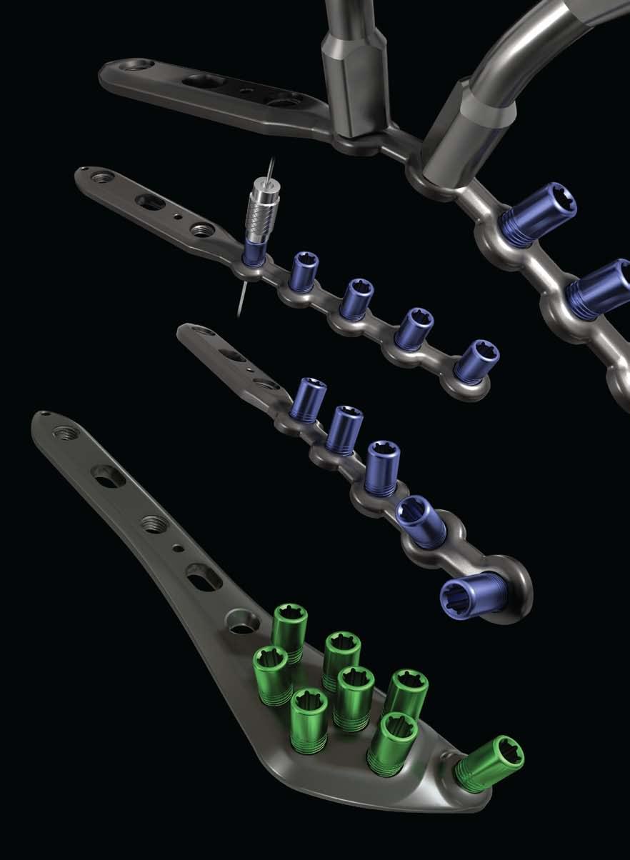
9 Fast, Accurate Surgeries F.A.S.T. Guide Technology Intra-operative Customization F.A.S.T. Guide Facilitate accurate drilling Pre-loaded and disposable Save time in the OR since no intra-operative assembly is required Color coded guides make identification easy: red guide = right, lime guide = left, blue guide = bilateral Flexible Plating Technology Flexible plating technology delivers intra-operative customization Composite plates can be contoured in both coronal and axial planes To facilitate surgical procedures even more, our Anatomic and Composite Fibula Plates come pre-loaded with Fixed Angle Screw Targeting Guides- F.A.S.T. Guides - that direct the trajectory of the drill right into the plate. 7
10
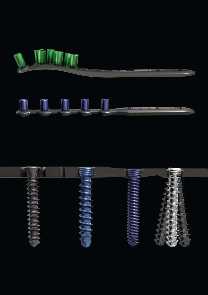
11 Versatility in Construct Locking, Non-Locking and Multi-Directional Screw Options Choose locking or non-locking screws, according to need Tapered, threaded screws lock into position when tightened to establish a fixed angle construct for strong fixation or when optimal screw purchase is required 3.5 mm low profile non-locking screws provide the same low profile design as locking screws for minimum soft tissue irritation Locking multi-directional screws (MDS) allow for up to 15 degrees of angulation from center for greater fixation Particularly helpful in challenging fracture cases, the multiple screw options allow plates and screws to be placed as close to the bone surface as possible. 9

12 Anatomic Fibula Locking Plate Proximal bullet tip facilitates submuscular plate insertion TiMAX for strength, biocompatibility and enhanced imaging capabilities over stainless steel Threaded holes for: locking 2.7 mm, 3.5 mm, 4.0 mm, and 3.5 mm multi-directional screws Compression holes in the shaft of the plate for: 2.7 mm standard non-locking screws 3.5 mm low profile and standard non-locking screws 4.0 mm standard non-locking screws - optional 1.6 mm F.A.S.T. Guide adapter for provisional fixation through F.A.S.T Guide insert K-wire holes for temporary fixation Low profile, anatomically contoured plate design for less soft tissue irritation Gradual transition for optimal stress distribution 3.5 mm multi-directional locking screws allow for up to 15 degrees of angulation from center Pre-assembled F.A.S.T. Guide inserts for easy drilling and bending of the tab Anatomical Fibula Locking Plate Proximal Width Distal Width Proximal Thickness Distal Thickness Lengths 23.4 mm 10.0 mm 2.8 mm 2.3 mm 3H, 4H, 6H, 8H and 10H 10

13 Fibula Composite Locking Plate Proximal bullet tip facilitates submuscular plate insertion TiMAX for strength, biocompatibility and enhanced imaging capabilities over stainless steel Compression holes in the shaft of the plate for: 2.7 mm standard non-locking screws 3.5 mm low profile and standard non-locking screws 4.0 mm standard non-locking screws - optional K-wire holes for temporary fixation 1.6 mm F.A.S.T. Guide adapter for provisional fixation through F.A.S.T Guide Threaded holes for: locking 2.7 mm, 3.5 mm, 4.0 mm, and 3.5 mm multi-directional screws Pre-assembled F.A.S.T. Guide inserts for easy drilling and bending Gradual transition for optimal stress distribution Low profile, bendable nodes for intra-operative customization 3.5 mm multi-directional locking screws allow for up to 15 degrees of angulation from center Fibula Composite Plate Proximal Width Distal Width Proximal Thickness Distal Thickness Lengths 10.0 mm 9.0 mm 2.8 mm 1.9 mm 6H, 7H, 8H, 10H, 12H and 14H 11
14 Screw Specifications 3.5 mm Low Profile Non-Locking Screw: Low profile head design reduces prominence beyond the plate Self tapping tip eases screw insertion Square drive for maximum torque delivery Type II anodized material for increased fatigue strength compared to stainless steel Screw (Cat. No XX) uses a 2.5 mm Drill Bit (Cat. No ) and can be installed in any threaded or compression hole in the plate Available in lengths of mm 2.7 mm Locking Cortical Screw: Self tapping tip minimizes the need for pre-tapping and eases screw insertion Tapered screw head helps ensure alignment of the screw head into the plate hole Tapered threaded head minimizes screw back-out and construct pullout T-15 drive Available in lengths of mm Screw (Cat. No XX) uses a 2.0 mm Marked Drill Bit (Cat. No ) 3.5 mm Locking Cortical Screw: Larger core diameter and shallower thread pitch for improved bending and shear strength compared to a standard 3.5 mm cortical screw Self tapping tip minimizes the need for pre-tapping and eases screw insertion Tapered screw head helps ensure alignment of the screw head into the plate hole Tapered threaded head minimizes screw back-out and construct pullout T-15 drive Available in lengths of mm Screw (Cat. No XX) uses a 2.7 mm Drill Bit (Cat. No ) 3.5 mm Locking Multi-Directional Screw: Cobalt-Chrome screw with large core diameter Multi-directional capability offers a 30 degree cone of angulation Creates own thread in plate to help provide strong and stable construct Screw head designed to prevent it from going through the threaded screw hole Self tapping tip minimizes the need for pre-tapping and eases screw insertion 2.2 mm square drive Available in lengths of mm Screw (Cat. No XX) uses a 2.7 mm Drill Bit (Cat. No ) 4.0 mm Locking Cancellous Screw: Self tapping tip minimizes the need for pre-tapping and eases screw insertion Tapered screw head helps ensure alignment of the screw head into the plate hole Tapered threaded head minimizes screw back-out and construct pullout T-15 drive Available in lengths of mm Screw (Cat. No XX) uses a 2.7 mm Drill Bit (Cat. No ) 12

.")
15 Plates Anatomic Fibula Locking Plate (Cat. No X-0XX) The Anatomic Fibula Plate is a low profile, anatomically contoured plate, designed to fit on the lateral aspect of the distal fibula. These thin plates are designed to minimize discomfort and soft tissue irritation around the ankle, while still having the strength needed to achieve rigid fixation of the distal fibula fracture. All plates come with F.A.S.T. Guide inserts inserted in the head portion for accurate drilling and placement of screws, with locking, lagging, or variable angle screw options available in the same construct (Figure 1). These plates are pre-contoured and need little, if any, secondary adjustments to their shape. A contourable F.A.S.T. Tab with a threaded screw hole is present distally to lock small distal fragments to the plate. This tab is adjustable with Composite Plate Benders that fit over the F.A.S.T. Guide inserts for easy and secure control. Contouring can be performed before application, or in situ. Figure 1 Anatomic Fibula Locking Plate Range available in left and right configurations. Fibula Composite Locking Plate (Cat. No XX) The Fibula Composite Plate is a low profile plate that combines the features of a locking compression plate with flexible plating technology. These thin plates are designed to minimize discomfort and soft tissue irritation around the ankle, while still having the strength needed to achieve rigid fixation of the fibula fracture. All plates come with F.A.S.T. Guide inserts for accurate drilling and placement of screws, with locking, lagging, or variable angle screw options available in the same construct (Figure 2). These plates provide the flexibility of in-situ contourability to mimic the patient's natural anatomy. Contourable plate nodes with threaded screw holes are present distally to lock small distal fragments to the plate. These locking and non-locking plate nodes are adjustable in the coronal and axial planes and are contourable with Composite Plate Benders that fit over the F.A.S.T. Guide inserts for easy and secure control. Contouring can be performed before application, or in situ. Figure 2 Fibula Composite Locking Plate Range. 13

16 Anatomic Plate Bending Figure 3 Plate benders have 2 ends: a cylindrical end and a square end. Anatomic Fibula Plate Bending In most cases the pre-contoured plate will fit without the need for further bending. The distal tab may be contoured as needed using F.A.S.T. Guide inserts and Composite Plate Benders (Cat. No ). To contour the F.A.S.T. Tab, place the cylindrical ends of the benders over opposing F.A.S.T. Guide inserts and exert pressure on the distal bender until the desired contour is achieved (Figures 3 and 4). Plates can be contoured outside the patient or intra-operatively. If the plate is contoured intraoperatively, then a 3.5 mm non-locking screw should be used in either a non-locking or locking hole to secure the plate to the bone. Note: Bending the distal tab beyond 20 degrees may result in breakage. Continuous bending will also fatigue the tab and cause it to break. Figure 4 Plate can be shaped using the benders over the F.A.S.T. Guide inserts. 14
. Figure 5 Secure the plate to the bone using 1.6 mm K-wires. Additionally, a 1.")
 may also be used to secure the plate temporarily.")

17 Application of the Anatomic Plate Provisional Fixation Once the fit of the Anatomic Plate has been confirmed both visually and fluoroscopically, 1.6 mm K-wires can be placed into the proximal K-wire holes to secure the plate to the bone (Figure 5). Figure 5 Secure the plate to the bone using 1.6 mm K-wires. Additionally, a 1.6 mm F.A.S.T. Guide Adapter (Cat. No ) can be inserted into a F.A.S.T. Guide insert to accept a 1.6 mm K-wire (Figure 6). Figure 6 Use 1.6 mm F.A.S.T. Guide Adapter and 1.6 mm K-wires to provisionally secure the plate to the bone. A provisional Fixation Pin (Cat. No /1) may also be used to secure the plate temporarily. The pin has a self-drilling tip and an AO quick connection for power insertion. Advance the pin slowly until the shoulder of the pin contacts the plate and pulls the plate down to the bone. Avoid advancing the pin beyond this point to prevent stripping of threads (Figure 7). Figure 7 A provisional Fixation Pin may also be used to secure the plate temporarily. 15
.")
18 Composite Plate Bending Figure 8 Use the cylindrical ends of the benders to achieve single plane bending. Fibula Composite Plate Bending Plates can be contoured to achieve an anatomic fit by utilizing the F.A.S.T. Guide inserts and Composite Plate Benders (Cat. No ). Use the cylindrical ends of the benders to achieve single plane bending. To contour the plate in the coronal plane by bending the plate toward the user (Figure 8) or away from the user (Figure 9), place the cylindrical ends of the benders over the F.A.S.T. Guide inserts and hold one bender as an anchor and manipulate with the other. The plates can be contoured up to 45 degrees at each bridge between the F.A.S.T. Guide inserts. Use the square ends of the benders to achieve multi-planar bending. To contour the plate axially or to achieve a twist shape (Figure 10), place the square ends of the benders over the F.A.S.T. Guide inserts and hold one bender as an anchor and manipulate with the other. The plates can be contoured up to 45 degrees at each bridge between the F.A.S.T. Guide inserts. Figure 9 The plates can be contoured up to 45 degrees at each bridge between the F.A.S.T. Guide inserts. Plates can be contoured outside the patient or intra-operatively. If the plate is contoured intraoperatively, then a 3.5 mm non-locking screw should be used in either a non-locking or locking hole to secure the plate to the bone. Note: Bending the distal tab beyond 45 degrees may result in breakage. Continuous bending will also fatigue the tab and cause it to break. Figure 10 Use the square ends of the benders to achieve multi-planar bending. 16
. Figure 11 Secure the plate to the bone using 1.6 mm K-wires. Additionally, a 1.")
 may also be used to secure the plate temporarily.")

19 Application of the Composite Plate Provisional Fixation Once the fit of the Composite Plate has been confirmed both visually and fluoroscopically, 1.6 mm K-wires can be placed into the proximal K-wire holes to secure the plate to the bone (Figure 11). Figure 11 Secure the plate to the bone using 1.6 mm K-wires. Additionally, a 1.6 mm F.A.S.T. Guide Adapter ( ) can be inserted into a F.A.S.T. Guide insert to accept a 1.6 mm K-wire (Figure 12). Figure 12 Use 1.6 mm F.A.S.T. Guide Adapter and 1.6 mm K-wires to provisionally secure plate to the bone. A provisional Fixation Pin (Cat. No /1) may also be used to secure the plate temporarily. The pin has a self-drilling tip and an AO quick connection for power insertion. Advance the pin slowly until the shoulder of the pin contacts the plate and pulls the plate down to the bone. Avoid advancing the pin beyond this point to prevent stripping of threads (Figure 13). Figure 13 A provisional Fixation Pin may also be used to secure the plate temporarily. 17
 in a Compression or Threaded Hole. Figure 14 Drill with the 2.0 mm Drill Bit through the 2.0/2.7 mm Drill Guide. Insert the 2.0 mm end of the 2.")
20 Screw Insertion The technique to insert screws onto the Anatomic and Composite plates is the same. Application of screws is shown on the Composite Plate. Insertion of a 2.7 mm Non-Locking Cortical Screw (Cat. No XX) in a Compression or Threaded Hole. Figure 14 Drill with the 2.0 mm Drill Bit through the 2.0/2.7 mm Drill Guide. Insert the 2.0 mm end of the 2.0/2.7 mm Drill Guide (Cat. No ) into the compression hole and drill through both cortices with the 2.0 mm Drill Bit (Cat. No ) (Figure 14). Measure the drilled hole with the Small Fragment Depth Gauge (Cat. No ) (Figure 15) by taking a direct reading from the NON-L line. NON-L Line Insert the appropriate length 2.7 mm Non-Locking Cortical Screw with the Screw Holder Sleeve (Cat. No ) over the 2.5 mm Hex Driver (Cat. No ) coupled to the Ratchet Handle (Cat. No ) (Figure 16). Figure 15 Take a depth reading from the NON-L Line. Note: For flush seating of the plate against the bone, use a non-locking screw prior to inserting a locked screw. If a non-locking screw is used in the distal part of the plate, then that F.A.S.T. Guide insert needs to be removed prior to drilling. Figure 16 Insert the 2.7 mm Non-Locking Cortical Screw using the 2.5 mm Hex Driver. 18
 (Figure 17). Measure the drilled hole with the Small Fragment Depth Gauge (Cat. No. 2142-35-100) (Figure 18) by taking a direct reading from the NON-L line. 3.")
 (Figure 19). Figure 17 Drill with the 2.5 mm Drill Bit through the 2.5/3.5 mm Drill Guide. 3.5 mm Low Profile Screw Insert the appropriate length 3.")
21 Screw Insertion Insertion of a 3.5 mm Non-Locking Cortical Screw in a Compression or Threaded Hole. Insert the 2.5 mm end of the 2.5/3.5 mm Drill Guide (Cat. No ) into the threaded or compression hole and drill through both cortices with the 2.5 mm Drill Bit (Cat. No ) (Figure 17). Measure the drilled hole with the Small Fragment Depth Gauge (Cat. No ) (Figure 18) by taking a direct reading from the NON-L line. 3.5 mm Standard Screw Insert the appropriate length 3.5 mm Non-Locking Cortical Screw with the Screw Holder Sleeve (Cat. No ) over the 2.5 mm Hex Driver (Cat. No ) coupled to the Ratchet Handle (Cat. No ) (Figure 19). Figure 17 Drill with the 2.5 mm Drill Bit through the 2.5/3.5 mm Drill Guide. 3.5 mm Low Profile Screw Insert the appropriate length 3.5 mm Low Profile Non-Locking Cortical Screw with the 2.2 mm Square Driver (Cat. No ) coupled to the Ratchet Handle (Cat. No ) (Figure 20). NON-L Line Note: For flush seating of the plate against the bone, use a non-locking screw prior to inserting a locked screw. If a non-locking screw is used in the distal part of the plate, then that F.A.S.T. Guide insert needs to be removed prior to drilling. Figure 18 Take a depth reading from the NON-L Line. Figure 19 Insert the 3.5 mm Non-Locking Cortical Screw using the 2.5 mm Hex Driver. Figure 20 Insert the low profile 3.5 mm Non-Locking Cortical Screw using the 2.2 mm Square Driver coupled to the Ratchet Handle. 19
 onto the 2.7 mm Drill Bit (Cat. No. 2142-27- 070) (Figure 21). Drill through the F.A.S.T. Guide insert until the far cortex is reached.")
22 Screw Insertion Figure 21 Slide the Measuring Drill Sleeve onto the 2.7 mm Drill Bit. Insertion of a 3.5 mm Cortical Locking Screw (Cat. No XX) or 4.0 mm Cancellous Locking Screw (Cat. No XX) into a Threaded Hole with a F.A.S.T. Guide insert. Slide the Measuring Drill Sleeve (Cat. No ) onto the 2.7 mm Drill Bit (Cat. No ) (Figure 21). Drill through the F.A.S.T. Guide insert until the far cortex is reached. Slide the Measuring Drill Sleeve onto the top end of the F.A.S.T. Guide insert and read the measurement of the Locking Screw length from the proximal end of the Drill Measuring Sleeve (Figure 22). Note: If a second method of measurement is desired, remove the F.A.S.T. Guide insert, then measure the drilled hole by taking a direct reading from the LOCK line on the Small Fragment Depth Gauge. Figure 22 Drill through the F.A.S.T. Guide insert with the 2.7 mm Drill Bit. Slide the Measuring Drill Sleeve to the top end of the F.A.S.T. Guide insert and read the measurement of the Locking Screw length from the proximal end. Next, remove the F.A.S.T. Guide insert with the T-15 Driver (Cat. No ) that is attached to the Ratchet Handle (Cat. No ) and insert the pre-determined Locking Screw using the T-15 Driver that is attached to the 2.0 Nm Torque- Limiting Screwdriver Handle (Cat. No ) (Figure 23). This can also be done using the Torque Limiting Power Adapter (Cat. No ) to power in the locking screws. Tip: If using power without a torque limiting power adapter, it should be at a slow speed. Perform all final screw tightening by hand with the Torque- Limiting Screwdriver. Figure 23 Insert the pre-determined Locking Screw using the T-15 Driver attached to the Torque-Limiting Driver Handle. 20
 (Figure 24). Place the 2.0 mm F.A.S.T. Guide Converter Handle (2312-18-010) through the F.A.S.T. Guide insert (Figure 25). Figure 24 Slide the 2.")
23 Screw Insertion Insertion of a 2.7 mm Cortical Locking Screw (Cat. No XX) into a Threaded Hole with a F.A.S.T. Guide insert. Slide the 2.0 mm Measuring Drill Sleeve (Cat. No ) onto the 2.0 mm Marked Drill Bit (Cat. No ) (Figure 24). Place the 2.0 mm F.A.S.T. Guide Converter Handle ( ) through the F.A.S.T. Guide insert (Figure 25). Figure 24 Slide the 2.0 mm Measuring Drill Sleeve onto the 2.0 mm Drill Bit. Drill through the F.A.S.T. Guide insert until the far cortex is reached. Slide the 2.0 mm Measuring Drill Sleeve onto the top end of the 2.0 mm F.A.S.T. Guide Converter Handle and read the measurement of the Locking Screw length from the window of the 2.0 mm Drill Measuring Sleeve (Figure 26). Note: If a second method of measurement is desired, remove the F.A.S.T. Guide insert, then measure the drilled hole by taking a direct reading from the LOCK line on the Small Fragment Depth Gauge. Figure 25 Place the 2.0 mm Converter Handle through the F.A.S.T. Guide insert. Next, remove the F.A.S.T. Guide insert with the T-15 Driver (Cat. No ) that is attached to the Ratchet Handle (Cat. No ) and insert the pre-determined Locking Screw using the T-15 Driver that is attached to the 2.0 Nm Torque- Limiting Screwdriver Handle (Cat. No ) (Figure 27). This can also be done using the Torque Limiting Power Adapter (Cat. No ) to power in the locking screws. Read from this line Tip: If using power without a torque limiting power adapter, it should be at a slow speed. Perform all final screw tightening by hand with the Torque-Limiting Screwdriver. Figure 26 Drill through the F.A.S.T. Guide insert with the 2.0 mm Drill Bit. Slide the Measuring Drill Sleeve to the top end of the Converter Handle and read the measurement of the Locking Screw length from the window. Figure 27 Insert the pre-determined Locking Screw using the T-15 Driver attached to the Torque-Limiting Driver Handle. 21
24 Screw Insertion The proximal end of the plate can now be secured to the bone. This can be achieved through the following options: Figure 28 Insert 2.7 mm Locking Drill Guide, drill with the 2.7 mm Drill Bit, and read the depth from the top of the Drill Guide. LOCK Line Insertion of a Locking Screw (3.5 mm Cortical Cat. No XX or 4.0 mm Cancellous Cat. No XX) in a Threaded Hole without a F.A.S.T. Guide insert. Screw the 2.7 mm Locking Drill Guide (Cat. No ) into a threaded plate hole until fully seated. Drill both cortices with the 2.7 mm Drill Bit to the desired depth and read the depth measurement from the drill bit at the top of the drill guide (Figure 28). Remove the 2.7 mm Locking Drill Guide. Note: If a second method of measurement is desired, remove the F.A.S.T. Guide insert, then measure the drilled hole by taking a direct reading from the LOCK line on the Small Fragment Depth Gauge (Figure 29). Figure 29 Take reading directly from the LOCK Line on the Small Fragment Depth Gauge. Insert the selected Locking Screw with the T-15 Driver (Cat. No ) coupled to the 2.0 Nm Torque-Limiting Screwdriver Handle (Cat. No ) (Figure 30). This can also be done using the Torque Limiting Power Adapter (Cat. No ) to power in the locking screws. Tip: If using power without a torque limiting power adapter, it should be at a slow speed. Perform all final screw tightening by hand with the Torque- Limiting Screwdriver. Figure 30 Insert the Locking Screw using the T-15 Driver coupled to the Torque-Limiting Screwdriver Handle. 22
 to the desired depth (Figure 31). Remove the 2.0 mm Locking Drill Guide.")
25 Screw Insertion Insertion of a 2.7 mm Cortical Locking Screw (Cat. No XX) into a Threaded Hole without a F.A.S.T. Guide insert. Screw the 2.0 mm Locking Drill Guide (Cat. No ) into a threaded plate hole until fully seated. Drill both cortices with the 2.0 mm Marked Drill Bit (Cat. No ) to the desired depth (Figure 31). Remove the 2.0 mm Locking Drill Guide. Measure the drilled hole with the Small Fragment Depth Gauge (Cat. No ) by taking a direct reading from the LOCK line (Figure 32) and insert the appropriate length 2.7 mm Locking Screw with the T-15 Driver (Cat. No ) that is attached to the 2.0 Nm Torque-Limiting Screwdriver Handle (Cat. No ) (Figure 33). Figure 31 Insert 2.0 mm Locking Drill Guide and drill with the 2.0 mm Drill Bit. LOCK Line This can also be done using the Torque Limiting Power Adapter (Cat. No ) to power in the locking screws. Tip: If using power without a torque limiting power adapter, it should be at a slow speed. Perform all final screw tightening by hand with the Torque- Limiting Screwdriver. Figure 32 Take reading directly from the LOCK Line on the Small Fragment Depth Gauge. Figure 33 Insert the Locking Screw using the T-15 Driver coupled to the Torque-Limiting Screwdriver Handle. 23

 into the plate hole and angle the drill as needed within an arc of 15 degrees (Figure 34). Drill through both cortices with the 2.7 mm Drill Bit (Cat. No. 2142-27-070) (Figure 35).")
 by taking a direct reading from the LOCK line (Figure 36) and insert the appropriate length 3.5 mm Multi- Directional Screw with the 2.2 mm Square Driver (Cat. No.")
26 Screw Insertion 3.5 mm Multi-Directional Screws Insertion of a 3.5 mm Multi-Directional Locking Screw in a Threaded Locking Hole (Cat. No XX). Figure 34 MDS Screw allows up to 15 degrees of angulation from center. Note: If inserting a 3.5 mm Multi-Directional Screw in threaded hole with a F.A.S.T. Guide insert, then first remove the F.A.S.T. Guide insert before commencing the technique. Additionally, note that the Torque Limiting Handle should not be used. Insert the 2.7 mm end of the 2.0/2.7 mm Drill Guide (Cat. No ) into the plate hole and angle the drill as needed within an arc of 15 degrees (Figure 34). Drill through both cortices with the 2.7 mm Drill Bit (Cat. No ) (Figure 35). Figure 35 Drill with the 2.7 mm Drill Bit through the 2.0/2.7 mm Drill Guide. Measure the drilled hole with the Small Fragment Depth Gauge (Cat. No ) by taking a direct reading from the LOCK line (Figure 36) and insert the appropriate length 3.5 mm Multi- Directional Screw with the 2.2 mm Square Driver (Cat. No ) coupled to the Ratchet Handle (Cat. No ) (Figure 37). LOCK Line Figure 36 Take a direct reading from the LOCK Line on the Depth Gauge. Figure 37 Insert the MDS screw using the 2.2 mm Square Driver coupled to the Rachet Handle. 24
27 Ordering Information Anatomic Fibula Locking Plates: Orientation Holes Length Left 3 95 mm Left mm Left mm Left mm Left mm Right 3 95 mm Right mm Right mm Right mm Right mm Fibula Composite Locking Plates: Orientation Holes Length Bilateral 6 77 mm Bilateral 7 92 mm Bilateral mm Bilateral mm Bilateral mm Bilateral mm 25
28 Ordering Information Screws: 2.7 mm Cortical Screws, Locking XX mm in 2 mm increments 2.7 mm Cortical Screws, Non-Locking XX mm in 2 mm increments mm in 5 mm increments 3.5 mm Cortical Screws, Locking XX mm in 2 mm increments mm in 5 mm increments 3.5 mm Multi-Directional Screws, Locking XX mm in 2 mm increments 3.5 mm Low Profile Cortical Screws, Non-Locking XX mm in 2 mm increments mm in 5 mm increments 3.5 mm Cortical Screws, Non-Locking XX mm in 2 mm increments mm in 5 mm increments 4.0 mm Cancellous Screws, Full Thread, Locking XX mm in 2 mm increments mm in 5 mm increments 4.0 mm Cancellous Screws, Full Thread, Non-Locking XX mm in 2 mm increments mm in 5 mm increments 4.0 mm Cancellous Screws, Partial Thread, Non-Locking XX mm in 2 mm increments mm in 5 mm increments 4.0 mm Cannulated Cancellous Screws, Partial Thread, Non-Locking XX mm in 2 mm increments mm in 5 mm increments 26
29 Notes 27
30 Notes 28
31 Notes
32 Screws, Plates, Intramedullary Nails, Compression Hip Screws, Pins and Wires Important: This Essential Product Information does not include all of the information necessary for selection and use of a device. Please see full labeling for all necessary information. Indications: The use of metallic surgical appliances (screws, plates, intramedullary nails, compression hip screws, pins and wires) provides the orthopaedic surgeon a means of bone fixation and helps generally in the management of fractures and reconstructive surgeries. These implants are intended as a guide to normal healing, and are NOT intended to replace normal body structure or bear the weight of the body in the presence of incomplete bone healing. Delayed unions or nonunions in the presence of load bearing or weight bearing might eventually cause the implant to break due to metal fatigue. All metal surgical implants are subjected to repeated stress in use, which can result in metal fatigue. Contraindications: Screws, plates, intramedullary nails, compression hip screws, pins and wires are contraindicated in: active infection, conditions which tend to retard healing such as blood supply limitations, previous infections, insufficient quantity or quality of bone to permit stabilization of the fracture complex, conditions that restrict the patient s ability or willingness to follow postoperative instructions during the healing process, foreign body sensitivity, and cases where the implant(s) would cross open epiphyseal plates in skeletally immature patients. Additional Contraindications for Compression Hip Screws only: Inadequate implant support due to the lack of medial buttress. Warnings and Precautions: Bone screws and pins are intended for partial weight bearing and non-weight bearing applications. These components cannot be expected to withstand the unsupported stresses of full weight bearing. Adverse Events: The following are the most frequent adverse events after fixation with orthopaedic screws, plates, intramedullary nails, compression hip screws, pins and wires: loosening, bending, cracking or fracture of the components or loss of fixation in bone attributable to nonunion, osteoporosis, markedly unstable comminuted fractures; loss of anatomic position with nonunion or malunion with rotation or angulation; infection and allergies and adverse reactions to the device material. Surgeons should take care when targeting and drilling for the proximal screws in any tibial nail with oblique proximal screws. Care should be taken as the drill bit is advanced to penetrate the far cortex. Advancing the drill bit too far in this area may cause injury to the deep peroneal nerve. Fluoroscopy should be used to verify correct positioning of the drill bit. Additional Adverse Events for Compression Hip Screw only: Screw cutout of the femoral head (usually associated with osteoporotic bone). Note: Do NOT remove F.A.S.T. Guide inserts prior to sterilization. Additional Contraindication for Orthopaedic Screws and Plates only: Cases with malignant primary or metastatic tumors which preclude adequate bone support or screw fixations, unless supplemental fixation or stabilization methods are utilized. Additional Contraindication for Retrograde Femoral Nailing: A history of septic arthritis of the knee and knee extension contracture with inability to attain at least 45º of flexion. 0M DePuy Orthopaedics, Inc. 700 Orthopaedic Drive Warsaw, IN USA Tel: +1 (800) Fax: +1 (574) DePuy International Ltd St Anthony s Road Leeds LS11 8DT England Tel: +44 (0) Fax: +44 (0) Printed in USA DePuy Orthopaedics, Inc. All rights reserved.
MaxTorque. surgical technique. Cannulated Screw System. Foot & Ankle. OrthoHelix Technology
 MaxTorque Cannulated Screw System OrthoHelix Technology surgical technique Foot & Ankle 2 M A X T O R Q U E C A N N U L A T E D S C R E W S Y S T E M Table of Contents Advantages 3 Indications 4 Contraindications
Integra. Capture Screw System SURGICAL TECHNIQUE
 Integra Capture Screw System SURGICAL TECHNIQUE Table of Contents Indications... 2 Contraindications... 2 System Description... 2 System Features... 2 Cannulated Low-Profile Screws (AC-Series) Overview...
Small Fragment Locking Compression Plate (LCP ) System Stainless Steel and Titanium TECHNIQUE GUIDE
 System Stainless Steel and Titanium TECHNIQUE GUIDE") Small Fragment Locking Compression Plate (LCP ) System Stainless Steel and Titanium TECHNIQUE GUIDE R Original Instruments and Implants of the Association for the Study of Internal Fixation AO ASIF Introduction
Small Fragment Locking Compression Plate (LCP ) System Stainless Steel and Titanium TECHNIQUE GUIDE R Original Instruments and Implants of the Association for the Study of Internal Fixation AO ASIF Introduction
OPERATIVE TECHNIQUE RIVAL REDUCE FRACTURE PLATING SYSTEM. foot & ankle trauma procedures
 OPERATIVE TECHNIQUE RIVAL REDUCE FRACTURE PLATING SYSTEM foot & ankle trauma procedures INTRODUCTION 3 SYSTEM DESCRIPTION 3 TECHNICAL DETAILS 4 SALES AND MARKETING CONFIGURATION 5 OPERATIVE TECHNIQUE 7
3.5 mm Cannulated Screw Technique Guide
 3.5 mm Cannulated Screw Technique Guide An Integral Part of the SYNTHES Cannulated Screw System Original Instruments and Implants of the Association for the Study of Internal Fixation AO ASIF The 3.5 mm
LCP Pilon Plate 2.7/3.5
 Surgical Technique LCP Locking Compression Plate Original Instruments and Implants of the Association for the Study of Internal Fixation AO/ASIF Table of contents Indications 3 Implants 4 Instruments 5
Instructions for Use. LCP Locking Compression Plate. Combine without Compromise.
 Instructions for Use LCP Locking Compression Plate. Combine without Compromise. Table of Contents LCP: Combine without Compromise 2 AO ASIF Principles of Osteosynthesis 4 Indications and Contraindications
MEDIALMAX System SURGICAL TECHNIQUE
 MAXLOCK EXTREME MEDIALMAX System SURGICAL TECHNIQUE Contents The MEDIALMAX Advantage Design Feature Various flex options POCKETLOCK Technology Anatomic design Advantage Provides the surgeon with multiple
OPERATIVE TECHNIQUE RIVAL BITE HEADED CANNULATED AND HEADLESS COMPRESSION SCREWS. foot & ankle applications
 OPERATIVE TECHNIQUE RIVAL BITE HEADED CANNULATED AND HEADLESS COMPRESSION SCREWS foot & ankle applications INTRODUCTION 3 SYSTEM DESCRIPTION 3 TECHNICAL DETAILS 4 SALES AND MARKETING CONFIGURATION 6 OPERATIVE
6.5 mm and 7.3 mm Cannulated Screws Technique Guide
 6.5 mm and 7.3 mm Cannulated Screws Technique Guide An Integral Part of the SYNTHES Cannulated Screw System Original Instruments and Implants of the Association for the Study of Internal Fixation AO ASIF
Technique Guide. 2.4/2.7 mm Locking Tarsal Plates. Talus Plate, Navicular Plate and Cuboid Plate.
 Technique Guide 2.4/2.7 mm Locking Tarsal Plates. Talus Plate, Navicular Plate and Cuboid Plate. Table of Contents Introduction 2.4/2.7 mm Locking Tarsal Plates 2 AO Principles 4 Indications 5 Clinical
Part of the DePuy Synthes Cannulated Screw System. 3.5 mm Cannulated Screws
 Part of the DePuy Synthes Cannulated Screw System 3.5 mm Cannulated Screws Surgical Technique Table of Contents Introduction 3.5 mm Cannulated Screws 2 AO Principles 3 Indications 4 Surgical Technique
WRIST SYSTEM. ARIX Volar Distal Radius Locking Plate System
 WRIST SYSTEM A Contents 3 4 7 14 15 16 19 21 Indications Product Overview Features & Benefits Ordering Information - Screws -2.5mm Self-Tapping Cortical Screws (Non-Locking) -2.5mm Self-Tapping Locking
3.5 MM low-profile cortex screws
 3.5 MM low-profile cortex screws Low-profle fxation option compatible with all Trauma 3.5 mm plates MechanicallY comparable To DEPUY SYNTHES TRAUMA standard 3.5 MM cortex screws low-profile option To MiniMiZe
S U R G I C A L T E C H N I Q U E TRAUMA & EXTREMITIES GROUP
 S U R G I C A L T E C H N I Q U E TRAUMA & EXTREMITIES GROUP TABLE OF CONTENTS ATN NAIL SYSTEM DESIGN RATIONALE INDICATIONS/CONTRAINDICATIONS PREOPERATIVE PLANNING AND PATIENT POSITIONING NAIL INSERTION
3.5 mm and 4.5 mm Curved Locking Compression Plates (LCP )
") For Minimally Invasive Osteosynthesis 3.5 mm and 4.5 mm Curved Locking Compression Plates (LCP ) Surgical Technique Table of Contents Introduction 3.5 mm and 4.5 mm Curved Locking Compression 2 Plates
For Minimally Invasive Osteosynthesis 3.5 mm and 4.5 mm Curved Locking Compression Plates (LCP ) Surgical Technique Table of Contents Introduction 3.5 mm and 4.5 mm Curved Locking Compression 2 Plates
OPERATIVE TECHNIQUE RIVAL VIEW PLATING SYSTEM. foot & ankle reconstruction procedures
 OPERATIVE TECHNIQUE RIVAL VIEW PLATING SYSTEM foot & ankle reconstruction procedures INTRODUCTION 3 SYSTEM DESCRIPTION 3 TECHNICAL DETAILS 4 SALES AND MARKETING CONFIGURATION 5 OPERATIVE TECHNIQUE 7 OPERATIVE
Technique Guide. 7.0 mm Cannulated Screws. Part of the Synthes Cannulated Screw System.
 Technique Guide 7.0 mm Cannulated Screws. Part of the Synthes Cannulated Screw System. Table of Contents Introduction 7.0 mm Cannulated Screws 2 AO Principles 3 Indications 4 Surgical Technique Surgical
VariAx DistalFibula. Foot & Ankle. Locking Plate System. Operative Technique
 VariAx DistalFibula Locking Plate System Operative Technique Foot & Ankle Distal Fibula Fracture Repair Polyaxial Locking Technology Low Profile Design VariAx 2 Color Coded Screws and Instruments VariAx
5th Metatarsal Fracture System Surgical Technique
 5th Metatarsal Fracture System Surgical Technique 5th Metatarsal Fracture System 5th Metatarsal Fracture System The 5th Metatarsal Fracture System (AR-8956S) is a uniquely designed screw and plate system
Distal Medial Tibia Plate Surgical Technique
 Locking Compression Technology by aap 1 Disclaimer This surgical technique is exclusively intended for medical professionals, especially physicians, and therefore may not be regarded as a source of information
Peanut Growth Control Plating System. Surgical Technique
 Peanut Growth Control Plating System Surgical Technique 1 Peanut Growth Control Plating System Table of Contents System Design Features... 2 Instrument Tray... 5 Implant Caddy... 6 Surgical Technique...
Features and Benefits 2. Indications and Pre-op Planning 7. Patient Positioning and Reduction 8. Entry and Canal Preparation 9.
 S U R G I C A L T EC H N I Q U E Contents Features and Benefits 2 Indications and Pre-op Planning 7 Patient Positioning and Reduction 8 Entry and Canal Preparation 9 Nail Insertion 12 Proximal Locking
Distal Fibula Plate SURGICAL TECHNIQUE
 MAXLOCK EXTREME Distal Fibula Plate SURGICAL TECHNIQUE Contents Key Design Features 3 Surgical Technique 4 Implants and Instruments 8 Proper surgical procedures and techniques are the responsibility of
VLP FOOT Variable Angle Locked Plating System
 Surgical Technique VLP FOOT Variable Angle Locked Plating System Surgical Technique Table of Contents Product overview Implant selection...2 Introduction...3 System overview...4 Indications...4 Design
Technique Guide. LCP Pilon Plate 2.7/3.5
 Technique Guide LCP Pilon Plate 2.7/3.5 LCP Pilon Plate 2.7/3.5 Table of contents Indications 3 Implants 4 Instruments 5 Surgical technique 6 Implant removal 12 Image intensifier control Warning This
Proximal Humerus Plate 3.5 Surgical Technique
 Locking Compression Technology by aap 1 Disclaimer This surgical technique is exclusively intended for medical professionals, especially physicians, and therefore may not be regarded as a source of information
Technique Guide. 4.5 mm Cannulated Screws. Part of the Synthes Cannulated Screw System.
 Technique Guide 4.5 mm Cannulated Screws. Part of the Synthes Cannulated Screw System. TableofContents Introduction 4.5 mm Cannulated Screws 2 AO Principles 3 Indications 4 Surgical Technique Surgical
Zimmer Natural Nail System. Cephalomedullary Nail Surgical Technique SMALL
 Zimmer Natural Nail System Cephalomedullary Nail Surgical Technique SMALL Zimmer Natural Nail System Cephalomedullary Nail Technique - Small 1 Zimmer Natural Nail System Cephalomedullary Nail Surgical
LCP Pilon Plate 2.7/3.5
 LCP Pilon Plate 2.7/3.5 Surgical Technique This publication is not intended for distribution in the USA. Instruments and implants approved by the AO Foundation. Table of contents Indications 2 Implants
7.0 mm Cannulated Screws
 Part of the DePuy Synthes Cannulated Screw System 7.0 mm Cannulated Screws Surgical Technique Table of Contents Introduction 7.0 mm Cannulated Screws 2 AO Principles 3 Indications 4 Surgical Technique
Mecron Cannulated Screws
 Surgical Technique and Ordering Information 2 Table of contents Description... 4 Indications for use... 4 Contraindications... 4 State-of-the-art design features... 5 Surgical Technique... 6 Surgery Steps
Zimmer Natural Nail System
 Zimmer Natural Nail System Cephalomedullary Nail Surgical Technique Compact Case - Short Nails Only STANDARD Zimmer Natural Nail System Cephalomedullary Nail Surgical Technique - Standard 1 Zimmer Natural
Zimmer Natural Nail System
 Zimmer Natural Nail System Cephalomedullary Nail Surgical Technique Compact Case- Short Nails Only SMALL Zimmer Natural Nail System Cephalomedullary Nail Technique - Small 1 Zimmer Natural Nail System
BioDrive Micro Screw System
 At Biomet, engineering excellence is our heritage and our passion. For over 25 years, through various divisions worldwide, we have applied the most advanced engineering and manufacturing technology to
Integra. Stainless Headed Compression Screw System SURGICAL TECHNIQUE
 Integra Stainless Headed Compression Screw System SURGICAL TECHNIQUE Table of Contents Design Rationale...2 Indications...2 Contraindications...2 Surgical Technique Step 1: Inserting Guide Wire... 3 Step
1.5 MM LCP SYSTEM. For treatment of fractures and arthrodeses of canines and felines SURGICAL TECHNIQUE
 1.5 MM LCP SYSTEM For treatment of fractures and arthrodeses of canines and felines SURGICAL TECHNIQUE TABLE OF CONTENTS INTRODUCTION 1.5 mm LCP System 2 AO Principles 4 SURGICAL TECHNIQUE Reduce Fracture
DART-FIRE. Small Screw System SURGICAL TECHNIQUE
 DART-FIRE Small Screw System SURGICAL TECHNIQUE DART-FIRE Small Screw System SURGICAL TECHNIQUE Contents Chapter 1 4 Chapter 2 6 Appendix 1 9 Appendix 2 11 Introduction DART-FIRE Small Screw System Surgical
2.4 mm and 3.0 mm Headless Compression Screws
 For Fixation of Small Bones and Small Bone Fragments 2.4 mm and 3.0 mm Headless s Surgical Technique Table of Contents Introduction 2.4 mm and 3.0 mm Headless 2 Technique Overview 4 AO Principles 5 Indications
VECTRA SURGICAL TECHNIQUE. Anterior cervical plate system. This publication is not intended for distribution in the USA.
 VECTRA Anterior cervical plate system This publication is not intended for distribution in the USA. SURGICAL TECHNIQUE Image intensifier control This description alone does not provide sufficient background
DART-FIRE. Small Screw System SURGICAL TECHNIQUE
 DART-FIRE Small Screw System SURGICAL TECHNIQUE DART-FIRE Small Screw System Surgical Technique Contents Chapter 1 4 Chapter 2 6 Chapter 3 7 Appendix 1 10 Appendix 2 12 Introduction Intended Use DART-FIRE
Variable Angle LCP Mesh Plate 2.4/2.7. Part of the Variable Angle LCP Forefoot/Midfoot System 2.4/2.7.
 Variable Angle LCP Mesh Plate 2.4/2.7. Part of the Variable Angle LCP Forefoot/Midfoot System 2.4/2.7. Surgical Technique This publication is not intended for distribution in the USA. Instruments and implants
LCP Pilon Plate 2.7/3.5. Surgical Technique
 LCP Pilon Plate 2.7/3.5 Surgical Technique Image intensifier control This description alone does not provide sufficient background for direct use of DePuy Synthes products. Instruction by a surgeon experienced
Variable Angle LCP Forefoot/Midfoot System 2.4/2.7. Procedure specific plates for osteotomies, arthrodeses and fractures of the foot.
 Instruction for Use Variable Angle LCP Forefoot/Midfoot System 2.4/2.7. Procedure specific plates for osteotomies, arthrodeses and fractures of the foot. Table of Contents Introduction VA-LCP Forefoot/Midfoot
Variable Angle LCP Tarsal Plates 2.4/2.7. Navicular Plate and Cuboid Plates.
 Variable Angle LCP Tarsal Plates 2.4/2.7. Navicular Plate and Cuboid Plates. Surgical Technique This publication is not intended for distribution in the USA. Instruments and implants approved by the AO
Ankle Fracture System. Surgical Technique STRENGTH FROM WITHIN
 Ankle Fracture System Surgical Technique STRENGTH FROM WITHIN Ankle Fracture System The Sonoma FibuLock nail is the first intramedullary device that has the same indications as plates and delivers anatomic
Technique Guide. Variable Angle LCP Opening Wedge Plates 2.4/2.7. Part of the Variable Angle LCP Forefoot / Midfoot System 2.4 / 2.7.
 Technique Guide Variable Angle LCP Opening Wedge Plates 2.4/2.7. Part of the Variable Angle LCP Forefoot / Midfoot System 2.4 / 2.7. Table of Contents Introduction Variable Angle LCP Opening Wedge Plates
DISTAL RADIUS PLATES 3.5 mm / ANGULARLY STABLE. Distal radius plates 3,5 mm / angularly stable. Locking bone screws. Cortical bone screw
 SURGICAL NÁSTROJE TECHNIQUE PRO ARTROSKOPII DISTAL INSTRUMENTS RADIUS PLATES FOR ARTHROSCOPY 3.5 mm / ANGULARLY STABLE Distal radius plates 3.5 mm / angularly stable Indication The plates are used for
Zimmer Natural Nail System
 Zimmer Natural Nail System Cephalomedullary Small Nail Surgical Technique Table of Contents Product Overview... 2 Implant Overview... 2 Indications... 3 Contraindications... 3 Surgical Technique... 4 Preoperative
Table of Contents 2-6. Introduction. Indications Surgical Technique. Ordering Information 15-24
 Table of Contents Introduction Product information ExtremiFix Midsize Large Screw Offering Headless Screw Characteristics Design Features & Benefits Instrumentation Technical Details Calibrated Drill Bits
DLS Dynamic Locking Screw. Combined with LCP Locking Compression Plate.
 DLS Dynamic Locking Screw. Combined with LCP Locking Compression Plate. Instructions for Use Discontinued June 2016 DSEM/TRM/0517/0844(1) Table of Contents Introduction DLS Dynamic Locking Screw 2 Indications
SpeedTip CCS 5.0, 7.0
 SURGICAL TECHNIQUE STEP BY STEP SpeedTip CCS 5.0, 7.0 Cannulated Compression Screws APTUS 2 SpeedTip CCS 5.0, 7.0 Cannulated Compression Screws Contents 3 Introduction Product Materials Indications Contraindications
VECTRA. SURGICAL TECHNIQUE. Anterior cervical plate system. This publication is not intended for distribution in the USA.
 VECTRA. Anterior cervical plate system. This publication is not intended for distribution in the USA. SURGICAL TECHNIQUE Contents Indications and contraindications Implants Vario Case Instruments Surgical
VariAx Fibula Locking Plate System
 VariAx Fibula Locking Plate System Operative Technique Distal Fibula Fracture Repair Polyaxial Locking Technology Low Profile Design 1 Contributing Surgeon: Bradley R. Merk, MD Associate Professor of Orthopaedic
ACCS Anterior Cervical Compression System TECHNIQUE GUIDE
 ACCS Anterior Cervical Compression System TECHNIQUE GUIDE Original Instruments and Implants of the Association for the Study of Internal Fixation AO ASIF ACCS Anterior Cervical Compression System The Anterior
Technique Guide. Quadrilateral Surface Plates 3.5. Part of the Low Profile Pelvic System 3.5.
 Technique Guide Quadrilateral Surface Plates 3.5. Part of the Low Profile Pelvic System 3.5. Table of Contents Introduction Quadrilateral Surface Plates 3.5 2 AO Principles 4 Indications 5 Surgical Technique
VARIABLE ANGLE LOCKING HAND SYSTEM
 VARIABLE ANGLE LOCKING HAND SYSTEM For fragment-specific fracture fixation with variable angle locking and locking technology SURGICAL TECHNIQUE TABLE OF CONTENTS INTRODUCTION Variable Angle Locking Hand
SpeedTip CCS 5.0, 7.0
 SURGICAL TECHNIQUE STEP BY STEP SpeedTip CCS 5.0, 7.0 Cannulated Compression Screws APTUS 2 SpeedTip CCS 5.0, 7.0 Cannulated Compression Screws SpeedTip CCS 5.0, 7.0 Cannulated Compression Screw 3 SpeedTip
HCS 1.5. The countersinkable compression screw.
 HCS 1.5. The countersinkable compression screw. Surgical Technique This publication is not intended for distribution in the USA. Instruments and implants approved by the AO Foundation. Table of Contents
DART-FIRE. Small Screw System SURGIC A L T ECHNIQUE
 DART-FIRE Small Screw System SURGIC A L T ECHNIQUE Contents Headline Headline PREFACE Chapter 1 4 Chapter 2 6 Chapter 3 7 Appendix A 10 Appendix B 12 Introduction Intended Use DART-FIRE Small Screw System
ISO Plate SURGICAL TECHNIQUE
 MINI MAXLOCK EXTREME ISO Plate SURGICAL TECHNIQUE Contents Table of Contents Key Design Features 2 Surgical Technique 3 Implants and Instruments 8 Key Design Features The MINI MAXLOCK EXTREME ISO (Intraosseous
MTP Set SURGICAL TECHNIQUE
 MINI MAXLOCK EXTREME MTP Set SURGICAL TECHNIQUE Contents Table of Contents Key Design Features 3 Surgical Technique Standard MTP Plate 4 MTP Plate with POCKETLOCK Technology 10 Implants and Instruments
HCS 2.4/3.0. The countersinkable compression screw.
 Technique Guide HCS 2.4/3.0. The countersinkable compression screw. Table of Contents Introduction Features and Benefits 2 Functional Principle 3 Indications 4 Surgical Technique Hand Scaphoid 5 Foot
Operative Technique Distal Fibula Fracture Repair Polyaxial Locking Technology Low Profile Design
 VariAx Fibula Locking Plate System Operative Technique Distal Fibula Fracture Repair Polyaxial Locking Technology Low Profile Design Contributing Surgeon: Bradley R. Merk, MD Associate Professor of Orthopaedic
Surgical Technique 1
 Surgical Technique 1 D-RAD SMART PACK Single-Use Volar Distal Radius Plating System Surgical Technique Table of Contents Indications... 3 Contraindications... 3 D-RAD SMART PACK product overview... 4 Instrumentation...
VARIABLE ANGLE LOCKING HAND SYSTEM
 VARIABLE ANGLE LOCKING HAND SYSTEM For fragment-specific fracture fixation with variable angle locking and locking technology Instruments and implants approved by the AO Foundation. This publication is
ACLP Anterior Cervical Locking Plate System TECHNIQUE GUIDE
 ACLP Anterior Cervical Locking Plate System TECHNIQUE GUIDE Instruments and implants approved by the AO Foundation ACLP Anterior Cervical Locking Plate System The ACLP System is designed to reduce the
Universal Humeral Nail
 990210009 INDEX Indications Preoperative Planning Patient Position Surgical Technique - Step 1 Open Humerus - Step 2 Calibrate The Nail - Step 3 Insert Nail - Step 4 Proximal Locking - Step 5 Assemble
TORNIER MAXLOCK EXTREME. Clavicle Plating System SURGICAL TECHNIQUE
 TORNIER MAXLOCK EXTREME Clavicle Plating System SURGICAL TECHNIQUE 2 Table of Contents: Key Design Features...4 Surgical Technique...5 Implants & Instruments...9 3 Key Design Features There are 7 anatomically
Technique Guide. Variable Angle LCP 1 st MTP Fusion Plates 2.4/2.7. Part of the Variable Angle LCP Forefoot / Midfoot System 2.4 / 2.7.
 Technique Guide Variable Angle LCP 1 st MTP Fusion Plates 2.4/2.7. Part of the Variable Angle LCP Forefoot / Midfoot System 2.4 / 2.7. Table of Contents Introduction Variable Angle LCP 1 st MTP Fusion
Surgical Technique. Customer Service:
 Patent Pending CAUTION: Federal Law (USA) restricts this device to sale by or on the order of a physician. Notes This page is blank INDICATIONS FOR USE The Extremity Medical Hallu X Intramedullary Fusion
Technique Guide. Modular Sternal Cable System. Flexibility and strength in sternal closure and repair.
 Technique Guide Modular Sternal Cable System. Flexibility and strength in sternal closure and repair. Table of Contents Introduction Overview 2 Indications and Contraindications 3 Surgical Technique A.
3.5 mm/ 2.7 mm LCP. PanCarPaL arthrodesis S PLate. BroCHUre. For treatment of carpal joints in dogs
 3.5 mm/ 2.7 mm LCP PanCarPaL arpal arthrodesis S PLate For treatment of carpal joints in dogs BroCHUre PLate DeSIGn the DePuy Synthes Vet 3.5 mm/2.7 mm LCP Pancarpal arthrodesis plate is intended for the
2.4 mm Cannulated Screw. An integral part of the Synthes Cannulated Screw System (CSS).
.") 2.4 mm Cannulated Screw. An integral part of the Synthes Cannulated Screw System (CSS). Surgical Technique This publication is not intended f distribution in the USA. and implants approved by the AO Foundation.
2.4 mm Cannulated Screw. An integral part of the Synthes Cannulated Screw System (CSS). Surgical Technique This publication is not intended f distribution in the USA. and implants approved by the AO Foundation.
Anterior Cervical Plate SURGICAL TECHNIQUE GUIDE. Surgeon Driven Innovation
 Anterior Cervical Plate SURGICAL TECHNIQUE GUIDE Surgeon Driven Innovation 1 The Snowmass Anterior Cervical Plate System is intended for the surgical treatment and correction of traumatic and pathologic
Small Plate and Screw System SURGICAL TECHNIQUE
 MINI MAXLOCK EXTREME Small Plate and Screw System SURGICAL TECHNIQUE Contents Key Design Features 2 Surgical Technique 3 Implants and Instruments 9 Proper surgical procedures and techniques are the responsibility
ORTHOLINK. 2 - Hole Wedge Osteotomy Plate SURGICAL TECHNIQUE
 MAXLOCK EXTREME ORTHOLINK 2 - Hole Wedge Osteotomy Plate SURGICAL TECHNIQUE Contents Key Design Features 3 Surgical Technique 4 Implants and Instruments 7 Proper surgical procedures and techniques are
Locking Small Fragment
 Locking Small Fragment Page 1 Locking Small Fragment Table of contents Implants 5 Operation technique 7 Inserting drill guides 7 Drilling 7 Length measurement 7 Inserting the measured screw 8 Different
MatrixMANDIBLE Preformed Reconstruction Plates. Preshaped to the mandibular anatomy.
 MatrixMANDIBLE Preformed Reconstruction Plates. Preshaped to the mandibular anatomy. Technique Guide CMF Matrix Table of Contents Introduction MatrixMANDIBLE Preformed Reconstruction Plates 2 AO Principles
3.5 mm/2.7 mm LCP. Pancarpal Arthrodesis Plate. For treatment of carpal joints in dogs
 3.5 mm/2.7 mm LCP Pancarpal Arthrodesis Plate For treatment of carpal joints in dogs Plate Design The DePuy Synthes Vet 3.5 mm/2.7 mm LCP Pancarpal Arthrodesis plate is intended for the treatment of hyperextension
Digital Compression Screw
 Digital Compression Screw Surgical Technique Contents Product The BioPro Digital Compression Screw is a stainless steel lag screw designed for digital fusions. Table of contents Indications & Contraindications
Ulna Shortening System 2.5
 SURGICAL TECHNIQUE STEP BY STEP Ulna Shortening System 2.5 APTUS Wrist 2 Ulna Shortening System 2.5 Contents 3 Introduction Product Materials Indications Contraindications Color Coding 4 General Instrument
Headless Compression and Twist-Off Screws
 Headless Compression and Twist-Off Screws The Next Generation Barouk Screw Surgical Technique Table of Contents System Introduction... 2 Headless Compression Screw... 4 Incision... 5 Lateral Release...
Distal Radius System 2.5
 SURGICAL TECHNIQUE STEP BY STEP Distal Radius System 2.5 APTUS Wrist 2 Distal Radius System 2.5 Contents 3 Introduction 3 Product Materials 3 Indications 3 Contraindications 3 Color Coding 3 Possible Combination
VariAxFibula. Fibula Fractures. Locking Plate System. Operative Technique
 Foot and Ankle VariAxFibula Locking Plate System Operative Technique Fibula Fractures Distal Fibula Fracture Repair Polyaxial Locking Technology Low Profile Design VariAx Fibula Locking Plate System Contributing
Technique Guide. Cable System. For Orthopaedic Trauma Surgery.
 Technique Guide Cable System. For Orthopaedic Trauma Surgery. Table of Contents Introduction Overview 2 AO Principles 4 Indications and Contraindications 5 Surgical Technique Standard Cerclage Technique
Vortex TRAUMATOLOGY. Vortex Distal Femur
 Vortex TRAUMATOLOGY Vortex Distal Femur 1 Content 1. Introduction 4 4. Implant list 16-17 The following surgical description contains general outlines for Vortex Distal Femur plating. However, the operating
Humeral Nail System Procedural Steps.
 Humeral Nail System Procedural Steps www.carbo-fix.com Table of Contents Introduction..3 Instrumentation Set... 8 Procedural Steps: Humeral Nail.........10 Procedural Steps: Proximal Humeral Nail.....13
Technique Guide. Occipito-Cervical Fusion System. Implants and instruments designed to optimize fixation to the occiput.
 Technique Guide Occipito-Cervical Fusion System. Implants and instruments designed to optimize fixation to the occiput. Table of Contents Introduction Overview 2 AO ASIF Principles 4 Indications and Contraindications
The Percutaneous Reduction Forceps Technique Guide
 The Percutaneous Reduction Forceps Technique Guide Indications + Product Overview Introduction The Percutaneous Reduction Forceps The Percutaneous Reduction Forceps facilitate standard technique for fixation
OsteoBridge IKA Intramedullary Knee Arthrodesis Fixation System. From the «BioBall Company» OsteoBridge Family
 From the «BioBall Company» OsteoBridge Family OsteoBridge IKA Intramedullary Knee Arthrodesis Fixation System The modular system for the fixation of the knee joint 01. OsteoBridge IKA The OsteoBridge IKA
Proximal Humerus System 3.5
 SURGICAL TECHNIQUE STEP BY STEP Proximal Humerus System 3.5 APTUS Shoulder 2 Proximal Humerus System 3.5 Contents 3 Introduction 3 Product Materials 3 Indications 3 Contraindications 3 Color Coding 3 Symbols
Integra. Tibio Talo Calcaneus Plate SURGICAL TECHNIQUE
 Integra Tibio Talo Calcaneus Plate SURGICAL TECHNIQUE Table of Contents Indications...02 Contraindications...02 Description...02 Surgical Technique...03 Step 1: Articular Surfaces Preparation...03 Step
Reflex Hybrid System Overview
 Spine Reflex Hybrid System Overview Anterior Cervical Plating System Introduction The Reflex Hybrid ACP System offers a low-profile anterior cervical plate along with a selection of bone screw types to
CSLP Variable Angle. For Use with the Cervical Spine Locking Plate System TECHNIQUE GUIDE. Self-drilling Screw. Variable Screw Angulation
 CSLP Variable Angle For Use with the Cervical Spine Locking Plate System TECHNIQUE GUIDE Self-drilling Screw Variable Screw Angulation Original Instruments and Implants of the Association for the Study
Cervical Solutions. Lineum OCT. Spine System. Surgical Technique Guide
 Cervical Solutions Lineum OCT Spine System Surgical Technique Guide 2 Lineum OCT Spine System Surgical Technique Guide Designed to encourage optimal screw placement and procedural efficiency Lineum OCT
Integra. HALLU -Lock M.T.P. Arthrodesis System SURGICAL TECHNIQUE
 Integra HALLU -Lock M.T.P. Arthrodesis System SURGICAL TECHNIQUE Table of Contents... 02 Indications... 02 Contraindications... 02 Surgical Technique... 03 Step 1: Incision... 03 Step 2: Preparation of
PAC PLATE A N T E R I O R C E RV I CA L P L AT E SYST E M S U R G I C A L T E C H N I Q U E
 PAC PLATE A N T E R I O R C E RV I CA L P L AT E SYST E M S U R G I C A L T E C H N I Q U E PAC PLATE ANTERIOR CERVICAL PLATE SYSTEM Table of Contents INTRODUCTION System Overview... 1 SURGICAL TECHNIQUE
Technique Guide. LCP Dynamic Helical Hip System (DHHS). Part of the Synthes Large Fragment LCP System.
. Part of the Synthes Large Fragment LCP System.") Technique Guide LCP Dynamic Helical Hip System (DHHS). Part of the Synthes Large Fragment LCP System. Table of Contents Introduction LCP Dynamic Helical Hip System (DHHS) 2 AO Principles 4 Indications
Technique Guide LCP Dynamic Helical Hip System (DHHS). Part of the Synthes Large Fragment LCP System. Table of Contents Introduction LCP Dynamic Helical Hip System (DHHS) 2 AO Principles 4 Indications
Surgical Technique. Acutrak Headless Compression Screw System
 Surgical Technique Acutrak Headless Compression Screw System Acumed is a global leader of innovative orthopaedic and medical solutions. We are dedicated to developing products, service methods, and approaches