Instruments for Removing DePuy Synthes Screws. Screw Removal Set
|
|
|
- Emma Sims
- 6 years ago
- Views:
Transcription
1 Instruments for Removing DePuy Synthes Screws Screw Removal Set Surgical Technique
2 Table of Contents Introduction Screw Removal Set 2 Surgical Technique Preoperative Planning and Preparation 6 Removal of Intact Screws 7 Removal of Broken Screws 9 Removal of Screws with Damaged Recesses 13 Removal of Jammed Screws 18 Product Information Instruments 22 Set List 28 MR Information The Screw Removal Set has not been evaluated for safety and compatibility in the MR environment. It has not been tested for heating, migration or image artifact in the MR environment. The safety of the Screw Removal Set in the MR environment is unknown. Scanning a patient who has this device may result in patient injury. Screw Removal Set Surgical Technique DePuy Synthes 1


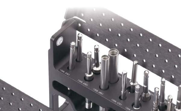
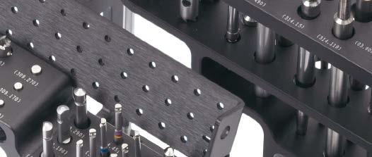
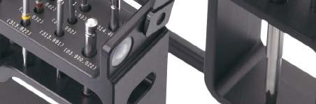
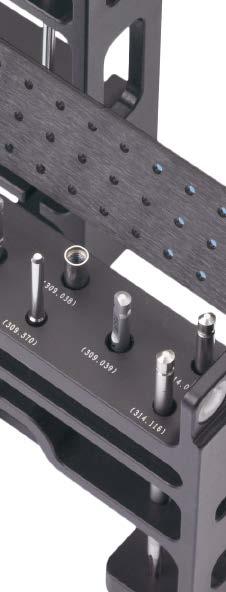
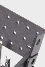
3 Screw Removal Set. Instruments for removing DePuy Synthes screws. The Screw Removal Set contains instruments required for removing intact screws or damaged screws that are difficult to remove. Modular design The modular design ensures that the assembly is ideally suited to requirements and the set is always complete. The clear layout makes the instruments easy to locate, thereby reducing the danger of selecting the wrong instrument. Comprehensive system All existing DePuy Synthes screws can be removed with the instruments supplied in the Screw Removal Set. This prevents delays caused by missing or incorrect instruments. The screw removal set contains screwdriver shafts for all DePuy Synthes screw sizes and drives, as well as extraction instruments for removing broken and damaged screws. The set contains instruments to remove all screws with the following drive recesses: Hex: 1.5 mm, 2.5 mm, 3.5 mm, and 4.0 mm StarDrive TM Recess: T4, T5, T6, T8, T15, T25, and T40 Cruciform: 1.0 mm, 1.3 mm, 1.5 mm, 2.0 mm, and 2.4 mm The set contains instruments for removing the following screws: Cortex screws Cancellous bone screws Shaft screws Cannulated screws Locking screws Locking bolts 2 DePuy Synthes Screw Removal Set Surgical Technique
4 Screw Removal Set. Instruments for removing DePuy Synthes screws. To remove intact screws Hex screwdriver shafts StarDrive Screwdriver shafts Cruciform screwdriver shafts To remove broken screws Hollow reamer: use counterclockwise to expose deeply seated broken screw shafts Extraction bolts: use counterclockwise to remove exposed broken screw shafts The following table shows which extraction instruments can be used to remove the various screw sizes. If several instruments can be used, select the one with the smallest external diameter. Hollow reamer and extraction bolt for screw diameter (and drive recess) Screw diameter (and drive recess) Recess 1.0 mm/1.3 mm/1.5 mm (Cruciform) 1.5 mm (1.5 mm Hex) 2.0 mm (Cruciform) 2.0 mm (1.5 mm Hex) 2.0 mm (T6 StarDrive Recess) 2.4 mm (Cruciform) 2.4 mm (T8 StarDrive Recess) 2.7 mm (2.5 mm Hex) 2.7 mm (T8 StarDrive Recess) 2.7 mm (T15 StarDrive Recess) 3.5 mm (2.5 mm Hex) 3.5 mm (T15 StarDrive Recess) 3.9 mm (2.5 mm Hex) 3.9 mm (3.5 mm Hex) 4.0 mm (2.5 mm Hex) 4.0 mm (3.5 mm Hex) 4.0 mm (T25 StarDrive Recess) 4.5 mm (3.5 mm Hex) 4.9 mm (3.5 mm Hex) 5.0 mm (3.5 mm Hex) 5.0 mm (T25 StarDrive Recess) 6.0 mm (T25 StarDrive Recess) 6.5 mm (3.5 mm Hex) Hollow reamers Extraction bolts Screw Removal Set Surgical Technique DePuy Synthes 3
5 Screw Removal Set. Instruments for removing DePuy Synthes screws. To remove screws with a damaged screw recess Conical extraction screws: use counterclockwise to remove screws with a damaged screw recess. Note: The conical tip of the extraction screw grasps the screw recess and the screw can be removed by turning counterclockwise. The table below shows screw diameter and geometry/recess size. It is not always possible to clearly allocate the extraction screw. Note: Always use the extraction screw with the largest possible diameter. Conical extraction screw for screw diameter (and drive recess) Recess Screw diameter (and drive recess) Conical extraction screws 1.5 mm (1.5 mm Hex) 2.0 mm (1.5 mm Hex) 2.0 mm (T6 StarDrive Recess) 2.4 mm (T8 StarDrive Recess) 2.7 mm (2.5 mm Hex) 2.7 mm (T8 StarDrive Recess) 2.7 mm (T15 StarDrive Recess) 3.5 mm (2.5 mm Hex) 3.5 mm (T15 StarDrive Recess) 3.9 mm (2.5 mm Hex) 3.9 mm (3.5 mm Hex) 4.0 mm (2.5 mm Hex) 4.0 mm (3.5 mm Hex) 4.0 mm (T25 StarDrive Recess) 4.5 mm (3.5 mm Hex) 4.9 mm (3.5 mm Hex) 5.0 mm (3.5 mm Hex) 5.0 mm (T25 StarDrive Recess) 6.0 mm (T25 StarDrive Recess) 6.5 mm (3.5 mm Hex) 4.0 mm Hex T40 StarDrive Recess* * EXPERT NAIL System 4 DePuy Synthes Screw Removal Set Surgical Technique
6 Screw Removal Set. Instruments for removing DePuy Synthes screws. To remove cannulated screws The following table shows instruments that are required for the removal of broken cannulated screws. The instruments shown in parentheses are suitable if the break is in the shaft. Extraction instruments for cannulated screws Screw diameter (and drive recess) Recess Extraction instruments 2.4 mm (T8 StarDrive Recess) 3.0 mm (Cruciform) 3.0 mm HCS (T8 StarDrive) 3.5 mm (2.5 mm Hex) 4.0 mm (2.5 mm Hex) 4.5 mm (3.5 mm Hex) 5.0 mm locking (4.0 mm Hex) 6.5 mm (4.0 mm Hex) 7.0 mm (3.5 mm Hex) 7.3 mm (4.0 mm Hex) ** ** () () () () () () () () () () () () () () () () () () () () ** Grips in the cannulation of the cannulated screw. Screw Removal Set Surgical Technique DePuy Synthes 5
 Recess geometry and dimension of the screws (hex, cruciform or StarDrive Recess) Screw diameter Any visible")

7 Preoperative Planning and Preparation Preoperative planning To ensure that the appropriate screw removal instruments are obtained, the surgeon should have the following information before implant removal: Implant manufacturer Implant type Time of implantation Material (steel, titanium) Recess geometry and dimension of the screws (hex, cruciform or StarDrive Recess) Screw diameter Any visible damage to the implant (eg, broken screw shaft) 1 Clean screw recess Instrument Sharp Hook Optional instrument Straight Sharp Hook Before removing screws, clean the screw recess. Free the screw recess from ingrown scars and bone tissue using the sharp hook to ensure that the screwdriver can be fully inserted. Check the condition and the geometry of the recess of the exposed screwhead. Note: Use the sharp hook to clean the recess if the soft tissue is not deep. If the screw is deep, use the straight sharp hook. 6 DePuy Synthes Screw Removal Set Surgical Technique

8 Removal of Intact Screws 1 Remove screw Instruments Handle, with mini quick coupling or Handle, with mini quick coupling Handle with quick coupling Small Universal Chuck with T-Handle Optional instruments AO Coupling Extension Shaft Small Screw Removal Forceps Large Screw Removal Forceps Connect the appropriate screwdriver shaft to a handle with quick coupling. Note: If the screw is deep in the tissue, attach the AO coupling extension shaft. Option Instead of using the handle with quick coupling, a small universal chuck with T-handle can be used. Connect the mini fragment screwdriver shafts to the handle with mini quick coupling. Screw Removal Set Surgical Technique DePuy Synthes 7

9 Removal of Intact Screws 1. Remove screw continued Insert the screwdriver fully into the screw recess. If necessary, lightly tap the screwdriver with a hammer. Note: Ensure that the screwdriver shafts are not damaged and are inserted on the same axis as the screw to be removed. The screw recess can be damaged if the screwdriver is not inserted straight or if it is blunt. Unscrew the screw. Note: To ensure that the loosened screw is not lost in the soft tissues, nor strips its thread in the bone, the screw can be held in position by extraction pliers for screws. Guide the extraction pliers along the screwdriver to the screwhead and grasp the screw directly behind the head. When all screws have been removed, the plate/internal fixator can be removed. 8 DePuy Synthes Screw Removal Set Surgical Technique


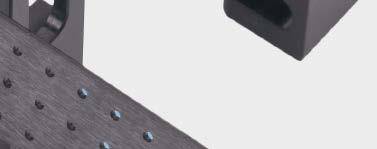
10 Removal of Broken Screws Option 1: Screw shaft is exposed 1 Expose the screw shaft Instrument Gouge Optional instrument Narrow Screw Removal Pliers If the screwhead is broken and the shaft is visible on the surface or slightly below the surface, use the gouge to remove the bone surrounding the screw shaft to approximately 5 mm in depth. Note: The narrow screw removal pliers can be used to expose the screw shaft, by using the slightly opened pliers as an awl (sharp edges on the outside of the clamps). 2 Remove screw Instrument Forceps for Screw Removal Optional instrument Narrow Screw Removal Pliers Remove the screw with the forceps for screw removal. Notes: Remove the screw stump by rotating it counterclockwise do not pull or bend. The narrow screw removal pliers can be used to remove the screw and require less space to grasp the screw shaft than the forceps for screw removal. Screw Removal Set Surgical Technique DePuy Synthes 9

11 Removal of Broken Screws Option 2: Screw shaft is not exposed 1 Expose the screw shaft Instruments Hollow Reamers Small Countersink Large Countersink Handle with quick coupling Optional instrument AO Coupling Extension Shaft If the screwhead is broken and the shaft is not visible, or the screw fragment is deeply seated, create an opening with the small or large countersink, then use the hollow reamer. The hollow reamer (complete) consists of three individual parts: reamer tube, centering pin, and shaft. To assemble the hollow reamer: 1 Connect the centering pin and the shaft (left-hand thread) 2 Screw the reamer tube over the centering pin (left-hand thread) Note: There is no thread connection between the centering pin and the shaft for hollow reamers , , and The reamer tube and the shaft are screwed together (left-hand thread). 11 DePuy Synthes Screw Removal Set Surgical Technique
. Note: Only use instruments with sharp edges.")
12 Removal of Broken Screws If the screw shaft has broken off less than approximately 5 mm below the bone surface, the hollow reamer can also be used without the centering pin. In this case, only connect the reamer tube and the shaft (left-hand thread). Note: Only use instruments with sharp edges. It is possible to use the hollow reamer with power tools, but this should be done very carefully. Connect the instruments with the handle with quick coupling. Guide the centering pin into the canal of the broken screw and turn the hollow reamer counterclockwise. Remove the centering pin when it reaches the screw fragment. Then continue to turn the reamer without the centering pin, approximately 5 mm below the screw. Note: If the screw is deep in the tissue, attach the AO coupling extension shaft. Screw Removal Set Surgical Technique DePuy Synthes 11

13 Removal of Broken Screws Option 2: Screw shaft is not exposed continued 2 Remove screw Instruments Extraction Bolts Handle with quick coupling Optional instrument AO Coupling Extension Shaft Connect the extraction bolt to the handle with quick coupling. Note: If the screw is deep in the tissue, attach the AO coupling extension shaft. Position the extraction bolt above the broken screw. Rotate counterclockwise while maintaining pressure and holding the extraction bolt as vertical as possible. This ensures a secure connection between the conical shape of the thread of the extraction bolt and the shaft of the screw. Turn counterclockwise until the screw shaft is completely removed. Note: The hollow reamer and the extraction bolt are left-turning (to be turned counterclockwise). During insertion, ensure that enough axial pressure is exerted and maintain alignment with the axis of the screw. 11 DePuy Synthes Screw Removal Set Surgical Technique
14 Removal of Screws with Damaged Recesses Option 1: Screwdriver turns freely in the recess 1 Remove screw Instruments Conical Extraction Screws Handle with quick coupling Optional instrument AO Coupling Extension Shaft Connect the conical extraction screw to the handle with quick coupling. Note: If the screw is deep in the tissue, attach the AO coupling extension shaft. Insert the tip of the conical extraction screw into the screw recess and hold it as vertical as possible. Turn counterclockwise, exerting pressure, until the extraction screw grasps into the screw recess. Continue to turn counterclockwise to remove the screw. Note: During insertion, ensure that enough axial pressure is exerted and maintain alignment with the axis of the screw. Only use sharp-edged extraction screws (recommendation: one extraction). Do not use extraction screws with power tools. Screw Removal Set Surgical Technique DePuy Synthes 11

15 Removal of Screws with Damaged Recesses Option 2: Screwdriver and conical extraction screw turn freely in the recess 1 Remove screw If the screwdriver and the conical extraction screw wear down the recess of the screw and turn freely in the recess, it may be possible to lightly predrill the screw recess to anchor the conical extraction screw deeper. 11 DePuy Synthes Screw Removal Set Surgical Technique
16 Removal of Screws with Damaged Recesses 2 Prepare for drilling Optional instruments mm Drill Sleeve Clip-on, for mm Drill Sleeve Clip-on, for mm Drill Sleeve Clip-on, for mm Drill Sleeve Clip-on, for mm Drill Sleeve Clip-on, for Drill Suction Device S 4.0 mm Carbide Drill Bit, sterile S 6.0 mm Carbide Drill Bit, sterile S 2.5 mm High Speed Drill Bit, sterile S 3.5 mm High Speed Drill Bit, sterile S 4.8 mm High Speed Drill Bit, sterile Drilling screws can cause drill chips that should be suctioned away. It is also important to cool the drill bit during the drilling process. The drill suction device allows efficient aspiration of the drill chips, while simultaneously cooling the drill bit. Before drilling, attach the appropriate drill sleeve to the drill suction device. Then connect the drill suction device to the irrigation system and the vacuum pump. To release the drill sleeve, press the side flange. Screw Removal Set Surgical Technique DePuy Synthes 11

17 Removal of Screws with Damaged Recesses Option 2: Screwdriver and conical extraction screw turn freely in the recess continued 3 Drill screw recess Irrigation Optional instruments Suction mm Drill Sleeve Clip-on, for mm Drill Sleeve Clip-on, for Drill Suction Device S 4.0 mm Carbide Drill Bit, sterile S 6.0 mm Carbide Drill Bit, sterile Switch on the rinsing equipment and the vacuum pump. Position the drill suction device on the relevant screw. Insert the drill bit into the drill sleeve, start the drill, then begin drilling. Carefully predrill the screw recess. Note: Do not interrupt the water supply. Ensure that the supply and waste hoses are not bent. Notes for drilling with metal drill bits: Precaution: Drill bits may not be reprocessed or resterilized. They are designed for single use only. Metal drill bits are hard and brittle. To prevent breakage, start drilling with the drill bit already revolving and maintain the chosen drill axis throughout the entire drilling process. Note: When drilling, cool with the drill suction device and aspirate the drill chips. Refer to page 21 for selection of appropriate drill bit. 11 DePuy Synthes Screw Removal Set Surgical Technique

18 Removal of Screws with Damaged Recesses 4 Remove screw Instruments Conical Extraction Screws Small Universal Chuck, with T-Handle Remove the screw with the conical extraction screw, as described on page 13. Screw Removal Set Surgical Technique DePuy Synthes 11
19 Removal of Jammed Screws 1 Remove broken instrument and screw Instruments Sharp Hook Forceps for Screw Removal If a broken instrument is in the recess, first attempt to remove the broken part of the instrument with a sharp hook and/or forceps for screw removal. If this attempt fails, proceed with the next step. 11 DePuy Synthes Screw Removal Set Surgical Technique

.")
20 Removal of Jammed Screws 2 Prepare for drilling Optional instruments mm Drill Sleeve Clip-on, for mm Drill Sleeve Clip-on, for mm Drill Sleeve Clip-on, for mm Drill Sleeve Clip-on, for mm Drill Sleeve Clip-on, for Drill Suction Device S 4.0 mm Carbide Drill Bit, sterile S 6.0 mm Carbide Drill Bit, sterile S 2.5 mm High Speed Drill Bit, sterile S 3.5 mm High Speed Drill Bit, sterile S 4.8 mm High Speed Drill Bit, sterile Select the appropriate drill bit and attach it to the universal chuck of the power tool and tighten (see page 21). If the screw is deep, the carbide drill bit extensions can be used. Before drilling, attach the appropriate drill sleeve to the drill suction device. Then connect the drill suction device to the irrigation system and the vacuum pump. To release the drill sleeve, press the side flange. Note: The use of the drill suction device allows efficient aspiration of the drill chips, while simultaneously cooling the drill bit. Screw Removal Set Surgical Technique DePuy Synthes 11

21 Removal of Jammed Screws 3 Drill off screwhead Switch on the rinsing equipment and the vacuum pump. Position the drill suction device on the relevant screw. Suction Irrigation Insert the drill bit into the drill sleeve, start the drill then begin drilling. Carefully drill off the screwhead. Align the axis of the drill with axis of the screw and maintain this alignment throughout the drilling process. Drill until the screwhead is detached or removed from the screw shaft. Note: Do not interrupt the water supply. Ensure that the supply and waste hoses are not bent. Remove the plate when it is no longer held in place by any screws. 22 DePuy Synthes Screw Removal Set Surgical Technique
22 Removal of Jammed Screws 4 Remove remaining screw shaft Proceed as for a broken screw. Note: Select the carbide drill bit to drill out screws from titanium implants. To remove broken instruments from the screw recess (eg, tips of screwdrivers, extraction screws), only use the carbide drill bits. Screw sizes Drill bits Drill bits suitable for Drill Drill Implant Instrument diameter type Titanium* steel steel 3.5 mm, 4.0 mm S 2.5 mm High speed mm, 4.0 mm, 4.5 mm, 5.0 mm S 3.5 mm High speed mm, 4.0 mm, 4.5 mm, 5.0 mm S 4.0 mm Carbide mm, 6.5 mm, 7.0 mm, 7.3 mm S 4.8 mm High speed mm, 6.5 mm, 7.0 mm, 7.3 mm S 6.0 mm Carbide good drilling properties + adequate drilling properties not recommended *Commercially pure (CP) titanium and titanium alloys (Ti-6Al-7Nb and Ti-6Al-4V) Screw Removal Set Surgical Technique DePuy Synthes 22


23 Instruments mm Carbide Drill Bit Extension mm Carbide Drill Bit Extension Drill Suction Device Drill Sleeve Clip-ons, for mm mm mm mm mm Straight Sharp Hook AO Coupling Extension Shaft 22 DePuy Synthes Screw Removal Set Surgical Technique

24 Instruments Small Screw Removal Forceps Large Screw Removal Forceps Hollow Reamers, complete for 3.5 mm and 4.0 mm screws for 6.5 mm and 7.0 mm screws for 1.5 mm screws for 2.0 mm screws for 2.7 mm screws for 4.5 mm screws Extraction Bolts for 3.5 mm and 4.0 mm screws for 6.5 mm and 7.0 mm screws for 1.5 mm screws for 2.0 mm screws for 2.7 mm screws for 4.5 mm and 5.0 mm screws Conical Extraction Screws for threaded washers for 1.5 mm and 2.0 mm screws for 2.7 mm, 3.5 mm and 4.0 mm screws for 3.5 mm screws for 4.5 mm and 6.5 mm screws for 7.3 mm cannulated screws Countersink, for 3.5 mm Cortex and 4.0 mm Cancellous Bone Screw Screw Removal Set Surgical Technique DePuy Synthes 22


25 Instruments Handle, with mini quick coupling, stainless steel Countersink, for 4.5 mm Cortex and 6.5 mm Cancellous Bone Screws Handle, with mini quick coupling Large Handle with quick coupling StarDrive Screwdriver Shafts T T mm, self-retaining mm, self-retaining mm, self-retaining T15, self-retaining T25, self-retaining mm Solid Hexgonal Screwdriver, 4.0 mm width across flats 22 DePuy Synthes Screw Removal Set Surgical Technique


26 Instruments Cruciform Screwdriver Shafts mm mm, self-retaining mm, self-retaining mm, 2.0 mm, self-retaining for 3.0 mm cannulated screws Hexagonal Screwdriver Shafts mm width across flats small, 2.5 mm width across flats large, 3.5 mm width across flats Large Hexgonal Screwdriver with T-Handle Cannulated Driver, for Threaded Washers, for 3.0 mm cannulated screws Sharp Hook Small Universal Chuck with T-Handle Screw Removal Set Surgical Technique DePuy Synthes 22


27 Instruments Narrow Screw Removal Pliers Forceps, for broken screw removal Hollow Gouge, for screw exposure 22 DePuy Synthes Screw Removal Set Surgical Technique
 309.180 for Hollow Reamer (309.200) 309.280 for Hollow Reamer (309.250) 309.480 for Hollow Reamer (309.450) Spare Centering Pin 309.")
 309.670 for Hollow Reamer (309.065) High Speed Drill Bits, sterile 309.503S 2.5 mm 309.504S 3.5 mm 309.506S 4.")
28 Also Available Carbide Drill Bits, sterile S 4.0 mm S 6.0 mm Spare Reamer Tubes for Hollow Reamer ( ) for Hollow Reamer ( ) for Hollow Reamer ( ) for Hollow Reamer ( ) for Hollow Reamer ( ) for Hollow Reamer ( ) Spare Centering Pin for Hollow Reamer ( ) for Hollow Reamer ( ) for Hollow Reamer ( ) for Hollow Reamer ( ) for Hollow Reamer ( ) for Hollow Reamer ( ) High Speed Drill Bits, sterile S 2.5 mm S 3.5 mm S 4.8 mm Screw Removal Set Surgical Technique DePuy Synthes 22


29 Screw Removal Set ( ) Graphic Case Graphic Case for Screw Removal Set Instruments Drill Sleeve Clip-ons, for mm mm mm mm mm Carbide Drill Bit Extensions mm mm Drill Suction Device Straight Sharp Hook AO Coupling Extension Shaft Screw Removal Forceps, small Screw Removal Forceps, large mm Cruciform Screwdriver Shaft, 100 mm mm Hexagonal Screwdriver Shaft, 100 mm T25 StarDrive Screwdriver Shaft, 100 mm T40 StarDrive Screwdriver Shaft, 100 mm Extraction Bolts for 3.5 mm and 4.0 mm screws for 6.5 mm and 7.0 mm screws for 1.5 mm screws for 2.0 mm screws for 2.7 mm screws for 4.5 mm screws Hollow Reamers, complete for 3.5 mm and 4.0 mm screws for 6.5 mm and 7.0 mm screws for 1.5 mm screws for 2.0 mm screws for 2.7 mm screws for 4.5 mm screws Note: For additional information, please refer to package insert. For detailed cleaning and sterilization instructions, please refer to or sterilization instructions, if provided. 22 DePuy Synthes Screw Removal Set Surgical Technique
30 Screw Removal Set ( ) Instruments continued Conical Extraction Device, for threaded washers Conical Extraction Screws for 1.5 mm and 2.0 mm cortex screws for 2.7 mm and 3.5 mm cortex screws for 3.5 mm screws for large screws and 4.9 mm bolts Countersink, for 3.5 mm cortex and 4.0 mm cancellous bone screws Handle, with mini quick coupling, stainless steel Countersink, for 4.5 mm cortex screws Handle, with mini quick coupling Large Handle, with quick coupling Screwdriver Blades, self-retaining, StarDrive, short mm mm mm mm Hexagonal Screwdriver Cruciform Screwdriver Shafts, self-retaining mm mm mm/2.0 mm Small Hexagonal Screwdriver Shaft StarDrive Screwdriver Shaft, quick coupling, T StarDrive Screwdriver Shaft, T25, self-retaining, 165 mm Large Hexagonal Screwdriver, with T-handle Large Hexagonal Screwdriver Shaft mm StarDrive Screwdriver Shaft Cannulated Driver for Threaded Washers, for 3.0 mm cannulated screws Cruciform Screwdriver Shaft Sharp Hook Conical Extraction Screw Small Universal Chuck, with T-handle Forceps, for broken screw removal Narrow Screw Removal Pliers Hollow Gouge, for broken screw exposure Also Available S 4.0 mm Carbide Drill Bit, sterile S 6.0 mm Carbide Drill Bit, sterile Spare Reamer Tubes for Hollow Reamer ( ) for Hollow Reamer ( ) for Hollow Reamer ( ) for Hollow Reamer ( ) for Hollow Reamer ( ) for Hollow Reamer ( ) Spare Centering Pins for Hollow Reamer ( ) for Hollow Reamer ( ) for Hollow Reamer ( ) for Hollow Reamer ( ) for Hollow Reamer ( ) for Hollow Reamer ( ) High Speed Drill Bits, sterile S 2.5 mm S 3.5 mm S 4.8 mm Screw Removal Set Surgical Technique DePuy Synthes 22
31 Limited Warranty and Disclaimer: DePuy Synthes products are sold with a limited warranty to the original purchaser against defects in workmanship and materials. Any other express or implied warranties, including warranties of merchantability or fitness, are hereby disclaimed. Please also refer to the package insert(s) or other labeling associated with the devices identified in this surgical technique for additional information. CAUTION: Federal Law restricts these devices to sale by or on the order of a physician. Some devices listed in this surgical technique may not have been licensed in accordance with Canadian law and may not be for sale in Canada. Please contact your sales consultant for items approved for sale in Canada. Not all products may currently be available in all markets. Manufactured or distributed by: Synthes USA Products, LLC 1302 Wrights Lane East West Chester, PA Synthes USA, LLC 1101 Synthes Avenue Monument, CO To order (USA): To order (Canada): Note: For recognized manufacturer, refer to the product label. DePuy Synthes All rights reserved. DSUS/TRM/1016/1197 5/17 DV
Instruments for removing Synthes screws. Screw Extraction Set. Handling Technique
 Instruments for removing Synthes screws Screw Extraction Set Handling Technique Image intensifier control This description alone does not provide sufficient background for direct use of DePuy Synthes products.
Part of the DePuy Synthes Cannulated Screw System. 3.5 mm Cannulated Screws
 Part of the DePuy Synthes Cannulated Screw System 3.5 mm Cannulated Screws Surgical Technique Table of Contents Introduction 3.5 mm Cannulated Screws 2 AO Principles 3 Indications 4 Surgical Technique
Screw Removal Set
 R 105.971 Screw Removal Set 105.971 Screw Removal Set 690.372 Screw Removal Set Graphic Case............................................ 1 ea. Instruments 309.035 Hollow Reamer, complete, for 3.5 mm Cortex,
7.0 mm Cannulated Screws
 Part of the DePuy Synthes Cannulated Screw System 7.0 mm Cannulated Screws Surgical Technique Table of Contents Introduction 7.0 mm Cannulated Screws 2 AO Principles 3 Indications 4 Surgical Technique
2.4 mm and 3.0 mm Headless Compression Screws
 For Fixation of Small Bones and Small Bone Fragments 2.4 mm and 3.0 mm Headless s Surgical Technique Table of Contents Introduction 2.4 mm and 3.0 mm Headless 2 Technique Overview 4 AO Principles 5 Indications
1.5 MM LCP SYSTEM. For treatment of fractures and arthrodeses of canines and felines SURGICAL TECHNIQUE
 1.5 MM LCP SYSTEM For treatment of fractures and arthrodeses of canines and felines SURGICAL TECHNIQUE TABLE OF CONTENTS INTRODUCTION 1.5 mm LCP System 2 AO Principles 4 SURGICAL TECHNIQUE Reduce Fracture
For the Reduction of Displaced Craniofacial Fractures. Threaded Reduction Tools and T-Handle
 For the Reduction of Displaced Craniofacial Fractures Threaded Reduction Tools and T-Handle Threaded Reduction Tools and T-Handle 2.4 mm (self-drilling) and 3.5 mm (self-tapping) Threaded Reduction Tools
For Minimally Invasive Application of Cerclage Wires. Cerclage Passer. Surgical Technique
 For Minimally Invasive Application of Cerclage Wires Cerclage Passer Surgical Technique Table of Contents Introduction Cerclage Passer 2 Surgical Technique Preparation 4 Insert Cerclage Passer 5 Connect
3.5 MM low-profile cortex screws
 3.5 MM low-profile cortex screws Low-profle fxation option compatible with all Trauma 3.5 mm plates MechanicallY comparable To DEPUY SYNTHES TRAUMA standard 3.5 MM cortex screws low-profile option To MiniMiZe
HCS 1.5. The countersinkable compression screw.
 HCS 1.5. The countersinkable compression screw. Surgical Technique This publication is not intended for distribution in the USA. Instruments and implants approved by the AO Foundation. Table of Contents
HCS 2.4/3.0. The countersinkable compression screw.
 Technique Guide HCS 2.4/3.0. The countersinkable compression screw. Table of Contents Introduction Features and Benefits 2 Functional Principle 3 Indications 4 Surgical Technique Hand Scaphoid 5 Foot
Technique Guide. 4.5 mm Cannulated Screws. Part of the Synthes Cannulated Screw System.
 Technique Guide 4.5 mm Cannulated Screws. Part of the Synthes Cannulated Screw System. TableofContents Introduction 4.5 mm Cannulated Screws 2 AO Principles 3 Indications 4 Surgical Technique Surgical
Manuals are subject to change; the most current version of each manual is always available online. Printed on: November 25, 2015
 Electronic INSTRUCTIONS FOR USE Manuals are subject to change; the most current version of each manual is always available online. Printed on: November 25, 2015 M PB Swiss Tools AG Bahnhofstrasse 24 CH-3457
DLS Dynamic Locking Screw. Combined with LCP Locking Compression Plate.
 DLS Dynamic Locking Screw. Combined with LCP Locking Compression Plate. Instructions for Use Discontinued June 2016 DSEM/TRM/0517/0844(1) Table of Contents Introduction DLS Dynamic Locking Screw 2 Indications
LCP Pilon Plate 2.7/3.5
 LCP Pilon Plate 2.7/3.5 Surgical Technique This publication is not intended for distribution in the USA. Instruments and implants approved by the AO Foundation. Table of contents Indications 2 Implants
Instructions for Use. LCP Locking Compression Plate. Combine without Compromise.
 Instructions for Use LCP Locking Compression Plate. Combine without Compromise. Table of Contents LCP: Combine without Compromise 2 AO ASIF Principles of Osteosynthesis 4 Indications and Contraindications
6.5 mm and 7.3 mm Cannulated Screws Technique Guide
 6.5 mm and 7.3 mm Cannulated Screws Technique Guide An Integral Part of the SYNTHES Cannulated Screw System Original Instruments and Implants of the Association for the Study of Internal Fixation AO ASIF
LCP Pilon Plate 2.7/3.5
 Surgical Technique LCP Locking Compression Plate Original Instruments and Implants of the Association for the Study of Internal Fixation AO/ASIF Table of contents Indications 3 Implants 4 Instruments 5
3.5 mm/ 2.7 mm LCP. PanCarPaL arthrodesis S PLate. BroCHUre. For treatment of carpal joints in dogs
 3.5 mm/ 2.7 mm LCP PanCarPaL arpal arthrodesis S PLate For treatment of carpal joints in dogs BroCHUre PLate DeSIGn the DePuy Synthes Vet 3.5 mm/2.7 mm LCP Pancarpal arthrodesis plate is intended for the
Technique Guide. 7.0 mm Cannulated Screws. Part of the Synthes Cannulated Screw System.
 Technique Guide 7.0 mm Cannulated Screws. Part of the Synthes Cannulated Screw System. Table of Contents Introduction 7.0 mm Cannulated Screws 2 AO Principles 3 Indications 4 Surgical Technique Surgical
MATRIX COMBO PLATING SYSTEM. Streamlined set for craniofacial and mandibular trauma and reconstruction
 MATRIX COMBO PLATING SYSTEM Streamlined set for craniofacial and mandibular trauma and reconstruction MATRIXCOMBO PLATING SET MATRIXCOMBO PLATING SET (01.503.400) The aim of surgical fracture treatment
3.5 mm/2.7 mm LCP. Pancarpal Arthrodesis Plate. For treatment of carpal joints in dogs
 3.5 mm/2.7 mm LCP Pancarpal Arthrodesis Plate For treatment of carpal joints in dogs Plate Design The DePuy Synthes Vet 3.5 mm/2.7 mm LCP Pancarpal Arthrodesis plate is intended for the treatment of hyperextension
Technique Guide. LCP Pilon Plate 2.7/3.5
 Technique Guide LCP Pilon Plate 2.7/3.5 LCP Pilon Plate 2.7/3.5 Table of contents Indications 3 Implants 4 Instruments 5 Surgical technique 6 Implant removal 12 Image intensifier control Warning This
OPERATIVE TECHNIQUE RIVAL BITE HEADED CANNULATED AND HEADLESS COMPRESSION SCREWS. foot & ankle applications
 OPERATIVE TECHNIQUE RIVAL BITE HEADED CANNULATED AND HEADLESS COMPRESSION SCREWS foot & ankle applications INTRODUCTION 3 SYSTEM DESCRIPTION 3 TECHNICAL DETAILS 4 SALES AND MARKETING CONFIGURATION 6 OPERATIVE
Integra. Stainless Headed Compression Screw System SURGICAL TECHNIQUE
 Integra Stainless Headed Compression Screw System SURGICAL TECHNIQUE Table of Contents Design Rationale...2 Indications...2 Contraindications...2 Surgical Technique Step 1: Inserting Guide Wire... 3 Step
Right-Angled Drilling and Screw Insertion. 90 Screwdriver. Surgical Technique
 Right-Angled Drilling and Screw Insertion 90 Screwdriver Surgical Technique 90 Screwdriver The DePuy Synthes 90 Screwdriver consists of a screwdriver handle, shaft, screw holder, screwholder insert and
3.5 mm Cannulated Screw Technique Guide
 3.5 mm Cannulated Screw Technique Guide An Integral Part of the SYNTHES Cannulated Screw System Original Instruments and Implants of the Association for the Study of Internal Fixation AO ASIF The 3.5 mm
LCP Pilon Plate 2.7/3.5. Surgical Technique
 LCP Pilon Plate 2.7/3.5 Surgical Technique Image intensifier control This description alone does not provide sufficient background for direct use of DePuy Synthes products. Instruction by a surgeon experienced
VECTRA SURGICAL TECHNIQUE. Anterior cervical plate system. This publication is not intended for distribution in the USA.
 VECTRA Anterior cervical plate system This publication is not intended for distribution in the USA. SURGICAL TECHNIQUE Image intensifier control This description alone does not provide sufficient background
OPERATIVE TECHNIQUE RIVAL REDUCE FRACTURE PLATING SYSTEM. foot & ankle trauma procedures
 OPERATIVE TECHNIQUE RIVAL REDUCE FRACTURE PLATING SYSTEM foot & ankle trauma procedures INTRODUCTION 3 SYSTEM DESCRIPTION 3 TECHNICAL DETAILS 4 SALES AND MARKETING CONFIGURATION 5 OPERATIVE TECHNIQUE 7
Cannulated Screws Ø 3.5 mm / 4.5 mm
 Cannulated Screws Ø / 4.5 mm Table of contents Implants Ø 4 Implants Ø 4.5 mm 6 Operation technique - Ø Cannulated Screws 9 Reduce fracture and insert guide wire 9 Determine the screw length 9 Drilling
ACLP Anterior Cervical Locking Plate System TECHNIQUE GUIDE
 ACLP Anterior Cervical Locking Plate System TECHNIQUE GUIDE Instruments and implants approved by the AO Foundation ACLP Anterior Cervical Locking Plate System The ACLP System is designed to reduce the
Innovative Solutions. Screw Removal Technique
 Innovative Solutions Screw Removal Technique Screw Removal Introduction Acumed is an industry leader in innovations for extremities and trauma. We are dedicated to pioneering solutions that benefit the
VARIABLE ANGLE LOCKING HAND SYSTEM
 VARIABLE ANGLE LOCKING HAND SYSTEM For fragment-specific fracture fixation with variable angle locking and locking technology Instruments and implants approved by the AO Foundation. This publication is
Cannulated Percutaneous Guiding System. For percutaneous placement of 3.5 mm pelvic and cortex screws in the pelvic area.
 Cannulated Percutaneous Guiding System. For percutaneous placement of 3.5 mm pelvic and cortex screws in the pelvic area. Technique Guide This publication is not intended for distribution in the USA. Instruments
IMPLANTEX. Product information. Instruments for removing screws
 IMPLANTEX Product information Instruments for removing screws TABLE OF CONTENTS DO YOU HAVE THE RIGHT EQUIPMENT TO HAND IN EMER- GENCY SITUATIONS? 3 4 5 6 8 Introduction General usage information Case
VECTRA. SURGICAL TECHNIQUE. Anterior cervical plate system. This publication is not intended for distribution in the USA.
 VECTRA. Anterior cervical plate system. This publication is not intended for distribution in the USA. SURGICAL TECHNIQUE Contents Indications and contraindications Implants Vario Case Instruments Surgical
SURGICAL TECHNIQUE GUIDE
 SURGICAL TECHNIQUE GUIDE DANGER indicates an imminently hazardous situation which, if not avoided, will result in death or serious injury. WARNING indicates a potentially hazardous situation which, if
Variable Angle LCP Mesh Plate 2.4/2.7. Part of the Variable Angle LCP Forefoot/Midfoot System 2.4/2.7.
 Variable Angle LCP Mesh Plate 2.4/2.7. Part of the Variable Angle LCP Forefoot/Midfoot System 2.4/2.7. Surgical Technique This publication is not intended for distribution in the USA. Instruments and implants
EX NAIL INSTRUMENTATION
 EX NAIL INSTRUMENTATION PRODUCT OVERVIEW OPENING INSTRUMENTS Awl Description Cannulated to accommodate a 3.0 mm Ball Tipped Reaming Rod 03.037.008 8.0 mm Cannulated Curved Awl Wire Guide Accessory Removable
3.5 mm and 4.5 mm Curved Locking Compression Plates (LCP )
") For Minimally Invasive Osteosynthesis 3.5 mm and 4.5 mm Curved Locking Compression Plates (LCP ) Surgical Technique Table of Contents Introduction 3.5 mm and 4.5 mm Curved Locking Compression 2 Plates
For Minimally Invasive Osteosynthesis 3.5 mm and 4.5 mm Curved Locking Compression Plates (LCP ) Surgical Technique Table of Contents Introduction 3.5 mm and 4.5 mm Curved Locking Compression 2 Plates
Lag Screw Device TECHNIQUE GUIDE. Indicated for symphyseal fracture fixation of the mandible. Instruments and implants approved by the AO Foundation
 Lag Screw Device TECHNIQUE GUIDE Indicated for symphyseal fracture fixation of the mandible Instruments and implants approved by the AO Foundation Lag Screw Device Indicated for symphyseal fracture fixation
Technique Guide. Quadrilateral Surface Plates 3.5. Part of the Low Profile Pelvic System 3.5.
 Technique Guide Quadrilateral Surface Plates 3.5. Part of the Low Profile Pelvic System 3.5. Table of Contents Introduction Quadrilateral Surface Plates 3.5 2 AO Principles 4 Indications 5 Surgical Technique
Titanium Modular Hand System. For fractures, replantations and reconstruction of the hand.
 Titanium Modular Hand System. For fractures, replantations and reconstruction of the hand. Plates precontoured for anatomic fit Instruments colorcoded for easy recognition Modules for 1.0 mm to 2.4 mm
VARIABLE ANGLE LOCKING HAND SYSTEM
 VARIABLE ANGLE LOCKING HAND SYSTEM For fragment-specific fracture fixation with variable angle locking and locking technology SURGICAL TECHNIQUE TABLE OF CONTENTS INTRODUCTION Variable Angle Locking Hand
Integra. Capture Screw System SURGICAL TECHNIQUE
 Integra Capture Screw System SURGICAL TECHNIQUE Table of Contents Indications... 2 Contraindications... 2 System Description... 2 System Features... 2 Cannulated Low-Profile Screws (AC-Series) Overview...
2.0. Contents Function control
 Contents 2.0 Drill bits 2.1 Medullary reamer heads 2.2 Burrs 2.3 Bone taps 2.4 Drill sleeves with serrated ends 2.5 Drill guides for plates 2.6 Aiming device 2.7 Pointed drill guide 2.8 Quick coupling
Ankle Fracture System. Surgical Technique STRENGTH FROM WITHIN
 Ankle Fracture System Surgical Technique STRENGTH FROM WITHIN Ankle Fracture System The Sonoma FibuLock nail is the first intramedullary device that has the same indications as plates and delivers anatomic
UJAM AA O RTHO PTY LTD 100 HYDE PARK C LO SE HYDE PARK 2196 W W W.UJAM AAO RTHO.C O M
 UJAM AA O RTHO PTY LTD 100 HYDE PARK C LO SE HYDE PARK 2196 W W W.UJAM AAO RTHO.C O M 4.0mm Cannulated Screw Set 112730000 112730100 Guide Wire, φ1.25 112730200 Guide Sleeve, φ1.25/φ3.0 110190300 Drill
DISTAL RADIUS PLATES 3.5 mm / ANGULARLY STABLE. Distal radius plates 3,5 mm / angularly stable. Locking bone screws. Cortical bone screw
 SURGICAL NÁSTROJE TECHNIQUE PRO ARTROSKOPII DISTAL INSTRUMENTS RADIUS PLATES FOR ARTHROSCOPY 3.5 mm / ANGULARLY STABLE Distal radius plates 3.5 mm / angularly stable Indication The plates are used for
Technique Guide. Modular Sternal Cable System. Flexibility and strength in sternal closure and repair.
 Technique Guide Modular Sternal Cable System. Flexibility and strength in sternal closure and repair. Table of Contents Introduction Overview 2 Indications and Contraindications 3 Surgical Technique A.
4.0 CANNULATED SCREW SYSTEM
 Surgical Technique 4.0 CANNULATED SCREW SYSTEM Surgical technique Table of contents Design features...2 Indications...3 Surgical technique...4 Inserting the screw...4 Extracting the screw...6 Catalog
2.4 mm Cannulated Screw. An integral part of the Synthes Cannulated Screw System (CSS).
.") 2.4 mm Cannulated Screw. An integral part of the Synthes Cannulated Screw System (CSS). Surgical Technique This publication is not intended f distribution in the USA. and implants approved by the AO Foundation.
2.4 mm Cannulated Screw. An integral part of the Synthes Cannulated Screw System (CSS). Surgical Technique This publication is not intended f distribution in the USA. and implants approved by the AO Foundation.
The Titanium Cannulated Lateral Entry Femoral Recon Nail. Expert nailing system with radiolucent instrumentation.
 The Titanium Cannulated Lateral Entry Femoral Recon Nail. Expert nailing system with radiolucent instrumentation. Technique Guide EXPERT Nailing System Table of Contents Introduction Titanium Cannulated
URS Degen. Top loading pedicle screw system for posterior stabilization.
 URS Degen. Top loading pedicle screw system for posterior stabilization. Technique Guide This publication is not intended for distribution in the USA. Table of Contents Introduction URS Degen 2 AO Principles
CSLP Variable Angle. For Use with the Cervical Spine Locking Plate System TECHNIQUE GUIDE. Self-drilling Screw. Variable Screw Angulation
 CSLP Variable Angle For Use with the Cervical Spine Locking Plate System TECHNIQUE GUIDE Self-drilling Screw Variable Screw Angulation Original Instruments and Implants of the Association for the Study
Occipito-Cervical Fusion System
 Implants and Instruments designed to enhance Fixation to the Occiput Occipito-Cervical Fusion System Surgical Technique Image intensifier control This description alone does not provide sufficient background
MINI INSTRUMENTS & IMPLANTS
 Page 1 MINI INSTRUMENTS & IMPLANTS Page 2 JACOB CHUCK DRILL BITS MIS-001 1.1MM 45MM LENGTH MIS-002 1.5MM 70MM LENGTH MIS-003 2.0MM 85MM LENGTH MIS-004 2.7MM 85MM LENGTH QUICK COUPLING DRILL BITS MIS-005
Cerclage Passer. For minimally invasive application of cerclage cables.
 Cerclage Passer. For minimally invasive application of cerclage cables. Handling Technique Cable application This publication is not intended for distribution in the USA. Instruments and implants approved
Veterinary Product Catalog. Implants Instruments Sets
 Veterinary Product Catalog Implants Sets Historical Background Before 1937, the treatment of fractures in large and small animals was confined mainly to casts and splints. Between this period and the mid-1960s,
Technique Guide. 2.4/2.7 mm Locking Tarsal Plates. Talus Plate, Navicular Plate and Cuboid Plate.
 Technique Guide 2.4/2.7 mm Locking Tarsal Plates. Talus Plate, Navicular Plate and Cuboid Plate. Table of Contents Introduction 2.4/2.7 mm Locking Tarsal Plates 2 AO Principles 4 Indications 5 Clinical
SpeedTip CCS 5.0, 7.0
 SURGICAL TECHNIQUE STEP BY STEP SpeedTip CCS 5.0, 7.0 Cannulated Compression Screws APTUS 2 SpeedTip CCS 5.0, 7.0 Cannulated Compression Screws Contents 3 Introduction Product Materials Indications Contraindications
Technique Chart. DHS/DCS One-Step Insertion Wrench. For use with DHS/DCS One-Step Lag Screws.
 Technique Chart DHS/DCS One-Step Insertion Wrench. For use with DHS/DCS One-Step Lag Screws. DHS/DCS One-Step Insertion Wrench DHS Triple Reamer (338.13) Assembly 338.10 8.0 mm Drill Bit 338.11 DHS Reaming
MEDICAL ADVANCED TECHNOLOGY EMERGENCY REMOVAL UNIVERSAL EXTRACTION SET. for Intramedullary Nail System
 MEDICAL ADVANCED TECHNOLOGY EMERGENCY REMOVAL UNIVERSAL EXTRACTION SET for Intramedullary Nail System introducing ourselve Manufacturer of surgical implants and medical devices. Solutions for patient orthopaedic
Variable Angle LCP Forefoot/Midfoot System 2.4/2.7. Procedure specific plates for osteotomies, arthrodeses and fractures of the foot.
 Instruction for Use Variable Angle LCP Forefoot/Midfoot System 2.4/2.7. Procedure specific plates for osteotomies, arthrodeses and fractures of the foot. Table of Contents Introduction VA-LCP Forefoot/Midfoot
Technique Guide Supplement. Standard DHS Lag Screw with LCP DHHS Sideplate.
 Technique Guide Supplement Standard DHS Lag Screw with LCP DHHS Sideplate. Table of Contents Surgical Technique Standard DHS Lag Screw with LCP DHHS 2 Sideplate Technique DHS One-step Lag Screw with DHHS
Technique Guide. Cable System. For Orthopaedic Trauma Surgery.
 Technique Guide Cable System. For Orthopaedic Trauma Surgery. Table of Contents Introduction Overview 2 AO Principles 4 Indications and Contraindications 5 Surgical Technique Standard Cerclage Technique
Occipito-Cervical Fusion System. Implants and instruments designed to optimize fixation to the occiput.
 Occipito-Cervical Fusion System. Implants and instruments designed to optimize fixation to the occiput. Technique Guide This publication is not intended for distribution in the USA. Instruments and implants
Universal Humeral Nail
 990210009 INDEX Indications Preoperative Planning Patient Position Surgical Technique - Step 1 Open Humerus - Step 2 Calibrate The Nail - Step 3 Insert Nail - Step 4 Proximal Locking - Step 5 Assemble
Technique Guide. Variable Angle LCP 1 st MTP Fusion Plates 2.4/2.7. Part of the Variable Angle LCP Forefoot / Midfoot System 2.4 / 2.7.
 Technique Guide Variable Angle LCP 1 st MTP Fusion Plates 2.4/2.7. Part of the Variable Angle LCP Forefoot / Midfoot System 2.4 / 2.7. Table of Contents Introduction Variable Angle LCP 1 st MTP Fusion
Technique Guide. Modular Sternal Cable System. Flexibility and strength in sternal closure and repair.
 Technique Guide Modular Sternal Cable System. Flexibility and strength in sternal closure and repair. Table of Contents Introduction Modular Sternal Cable System 2 Indications 4 Modular Sternal Closure
ALLGEMEINE INSTRUMENTE FÜR KNOCHENCHIRURGIE GENERAL INSTRUMENTS FOR BONE SURGERY INSTRUMENTAL GENERAL
 42-09-0009 3 Jaw Chuck Adaptor, Jacobs to quick coupling, incl. Wrench 42-09-0010 3 Jaw Chuck Adaptor, Jacobs to Quagrangular, incl. Wrench 42-09-0011 3 Jaw Chuck Adaptor, 3 Jaw to Quadrangular, incl.
400 SERIES GRINDER PUMPS 41502, 42202,43302, AND MODELS
 Section: MOYNO 500 PUMPS Page: 1 of 6 Date: March 1, 1998 SERVICE MANUAL MOYNO 500 PUMPS 400 SERIES GRINDER PUMPS 41502, 42202,43302, AND 44402 MODELS DESIGN FEATURES Housing: Cast iron Pump Rotor: Chrome
OPERATIVE TECHNIQUE RIVAL VIEW PLATING SYSTEM. foot & ankle reconstruction procedures
 OPERATIVE TECHNIQUE RIVAL VIEW PLATING SYSTEM foot & ankle reconstruction procedures INTRODUCTION 3 SYSTEM DESCRIPTION 3 TECHNICAL DETAILS 4 SALES AND MARKETING CONFIGURATION 5 OPERATIVE TECHNIQUE 7 OPERATIVE
SpeedTip CCS 5.0, 7.0
 SURGICAL TECHNIQUE STEP BY STEP SpeedTip CCS 5.0, 7.0 Cannulated Compression Screws APTUS 2 SpeedTip CCS 5.0, 7.0 Cannulated Compression Screws SpeedTip CCS 5.0, 7.0 Cannulated Compression Screw 3 SpeedTip
Expert HAN. Expert Hindfoot Arthrodesis Nail.
 Expert HAN. Expert Hindfoot Arthrodesis Nail. Technique Guide Expert Nailing System Table of Contents Introduction Expert Hindfoot Arthrodesis Nail 2 AO Principles 4 Indications 5 Surgical Technique Preoperative
OCCIPITO-CERVICAL FUSION SYSTEM Implants and instruments designed to optimize fixation to the occiput
 OCCIPITO-CERVICAL FUSION SYSTEM Implants and instruments designed to optimize fixation to the occiput Instruments and implants approved by the AO Foundation. This publication is not intended for distribution
MaxTorque. surgical technique. Cannulated Screw System. Foot & Ankle. OrthoHelix Technology
 MaxTorque Cannulated Screw System OrthoHelix Technology surgical technique Foot & Ankle 2 M A X T O R Q U E C A N N U L A T E D S C R E W S Y S T E M Table of Contents Advantages 3 Indications 4 Contraindications
Surgical Technique. Customer Service:
 Patent Pending CAUTION: Federal Law (USA) restricts this device to sale by or on the order of a physician. Notes This page is blank INDICATIONS FOR USE The Extremity Medical Hallu X Intramedullary Fusion
The Percutaneous Reduction Forceps Technique Guide
 The Percutaneous Reduction Forceps Technique Guide Indications + Product Overview Introduction The Percutaneous Reduction Forceps The Percutaneous Reduction Forceps facilitate standard technique for fixation
Technique Guide. Synapse System. An enhanced set of instruments and implants for posterior stabilization of the cervical and upper thoracic spine.
 Technique Guide Synapse System. An enhanced set of instruments and implants for posterior stabilization of the cervical and upper thoracic spine. Table of Contents Introduction Synapse System 2 AO Principles
Small Fragment Locking Compression Plate (LCP ) System Stainless Steel and Titanium TECHNIQUE GUIDE
 System Stainless Steel and Titanium TECHNIQUE GUIDE") Small Fragment Locking Compression Plate (LCP ) System Stainless Steel and Titanium TECHNIQUE GUIDE R Original Instruments and Implants of the Association for the Study of Internal Fixation AO ASIF Introduction
Small Fragment Locking Compression Plate (LCP ) System Stainless Steel and Titanium TECHNIQUE GUIDE R Original Instruments and Implants of the Association for the Study of Internal Fixation AO ASIF Introduction
ACCS Anterior Cervical Compression System TECHNIQUE GUIDE
 ACCS Anterior Cervical Compression System TECHNIQUE GUIDE Original Instruments and Implants of the Association for the Study of Internal Fixation AO ASIF ACCS Anterior Cervical Compression System The Anterior
Technique Guide. Occipito-Cervical Fusion System. Implants and instruments designed to optimize fixation to the occiput.
 Technique Guide Occipito-Cervical Fusion System. Implants and instruments designed to optimize fixation to the occiput. Table of Contents Introduction Overview 2 AO ASIF Principles 4 Indications and Contraindications
Variable Angle LCP Tarsal Plates 2.4/2.7. Navicular Plate and Cuboid Plates.
 Variable Angle LCP Tarsal Plates 2.4/2.7. Navicular Plate and Cuboid Plates. Surgical Technique This publication is not intended for distribution in the USA. Instruments and implants approved by the AO
OsteoBridge IKA Intramedullary Knee Arthrodesis Fixation System. From the «BioBall Company» OsteoBridge Family
 From the «BioBall Company» OsteoBridge Family OsteoBridge IKA Intramedullary Knee Arthrodesis Fixation System The modular system for the fixation of the knee joint 01. OsteoBridge IKA The OsteoBridge IKA
Technique Guide. LCP Dynamic Helical Hip System (DHHS). Part of the Synthes Large Fragment LCP System.
. Part of the Synthes Large Fragment LCP System.") Technique Guide LCP Dynamic Helical Hip System (DHHS). Part of the Synthes Large Fragment LCP System. Table of Contents Introduction LCP Dynamic Helical Hip System (DHHS) 2 AO Principles 4 Indications
Technique Guide LCP Dynamic Helical Hip System (DHHS). Part of the Synthes Large Fragment LCP System. Table of Contents Introduction LCP Dynamic Helical Hip System (DHHS) 2 AO Principles 4 Indications
SYnaPSe oct SYSteM. An enhanced set of instruments and implants for posterior stabilization of the upper spine
 SYnaPSe oct SYSteM An enhanced set of instruments and implants for posterior stabilization of the upper spine SurgIcal technique Table of Contents Introduction SYNAPSE OCT System 2 AO Principles 5 Indications
Fixation screw ENGLISH
 Fixation screw ENGLISH CONCEPT The QWIX fixation screws were designed for extremity fixation and provide speed and precision for challenging surgical situations. The QWIX screw s unique design allows:
Technique Guide. Synapse System. An enhanced set of implants and instruments for posterior stabilization of the cervical and upper thoracic spine.
 Technique Guide Synapse System. An enhanced set of implants and instruments for posterior stabilization of the cervical and upper thoracic spine. Image intensifier control Warning This description alone
Orthopedic Bone Nail System Universal Humeral Nail
 Orthopedic Bone Nail System Universal Humeral Nail Surgical Technique Manual Note: The surgical procedures should be performed under the guidance of qualified skilled orthopedic surgeons, and this surgical
DART-FIRE. Small Screw System SURGICAL TECHNIQUE
 DART-FIRE Small Screw System SURGICAL TECHNIQUE DART-FIRE Small Screw System Surgical Technique Contents Chapter 1 4 Chapter 2 6 Chapter 3 7 Appendix 1 10 Appendix 2 12 Introduction Intended Use DART-FIRE
Xia 3 Reference Guide. Version 3-August 2015
 Xia 3 Reference Guide Xia 3 Reference Guide Version 3-August 2015 Table of Contents Implants 03 Blocker 03 Monoaxial Screws 04 Polyaxial Screws 05 Uniplanar Screws 06 Iliac Bolts 07 Rod-to-Rod Connectors
Mecron Cannulated Screws
 Surgical Technique and Ordering Information 2 Table of contents Description... 4 Indications for use... 4 Contraindications... 4 State-of-the-art design features... 5 Surgical Technique... 6 Surgery Steps
Cable System. For Orthopaedic Trauma Surgery.
 Cable System. For Orthopaedic Trauma Surgery. Surgical Technique This publication is not intended for distribution in the USA. Instruments and implants approved by the AO Foundation. Image intensifier
Surgical Technique Guide
 Surgical Technique Guide Xtract-All Screw V.2 Case FCD-065 REV: 02 Introduction The Xtract-All Screw V.2 system (S9SCRW) is a cannulated universal extraction system intended to remove virtually all broken,
Small Plate and Screw System SURGICAL TECHNIQUE
 MINI MAXLOCK EXTREME Small Plate and Screw System SURGICAL TECHNIQUE Contents Key Design Features 2 Surgical Technique 3 Implants and Instruments 9 Proper surgical procedures and techniques are the responsibility
Top Loading Pedicle Screw and Hook System for Posterior Stabilization. URS System. Surgical Technique
 Top Loading Pedicle Screw and Hook System for Posterior Stabilization URS System Surgical Technique Image intensifier control This description alone does not provide sufficient background for direct use
Distal Radius System 2.5
 SURGICAL TECHNIQUE STEP BY STEP Distal Radius System 2.5 APTUS Wrist 2 Distal Radius System 2.5 Contents 3 Introduction 3 Product Materials 3 Indications 3 Contraindications 3 Color Coding 3 Possible Combination
SYNAPSE SYSTEM An enhanced set of implants and instruments for posterior stabilization of the cervical and upper thoracic spine
 SYNAPSE SYSTEM An enhanced set of implants and instruments for posterior stabilization of the cervical and upper thoracic spine Instruments and implants approved by the AO Foundation. This publication