The Titanium Cannulated Lateral Entry Femoral Recon Nail. Expert nailing system with radiolucent instrumentation.
|
|
|
- Terence Butler
- 6 years ago
- Views:
Transcription

1 The Titanium Cannulated Lateral Entry Femoral Recon Nail. Expert nailing system with radiolucent instrumentation. Technique Guide EXPERT Nailing System
2 Table of Contents Introduction Titanium Cannulated Lateral Entry Femoral Recon Nail 2 Expert Nailing System with Radiolucent Instrumentation AO Principles 4 Indications 5 Clinical Cases 6 Surgical Technique Preoperative Planning 8 Opening the Femur 12 Inserting the Nail 20 Locking Options 24 Proximal Locking 25 Proximal Locking Recon 31 Distal Locking 35 End Cap Insertion 42 Implant Removal 44 Product Information Implant Specifications 50 Implants 51 Instruments 57 Set Lists 64 Image intensifier control Titanium Cannulated Lateral Entry Femoral Recon Nail Expert System Technique Guide Synthes
 for reamed or unreamed techniques Lengths from 300 mm to 480 mm, in")

3 Titanium Cannulated Lateral Entry Femoral Recon Nail Expert System Expert nailing system with radiolucent instrumentation Advanced solutions Nail features Design accommodates a lateral entry site through the greater trochanter Anatomic nail design based on a femoral canal study 1 Cannulated nails (from 9 mm to 16 mm diameter) for reamed or unreamed techniques Lengths from 300 mm to 480 mm, in 20 mm increments Enhanced distal locking options Oblique distal locking hole offers enhanced stability of distal fractures Improved instrumentation Easy-to-use instrumentation facilitates the surgical procedure Ball-tip reaming rod can be removed through the nail and insertion instruments eliminating the need for an exchange tube Radiolucent aiming arms and insertion handles End caps Prevent ingrowth of tissue and facilitate nail extraction Self-retaining, T40 StarDrive recess for easy pickup and insertion of end cap Cannulated for insertion over a guide wire 0 mm end cap sits flush with nail 5, 10, 15, and 20 mm end caps extend nail height if nail is overinserted 20 mm 15 mm 10 mm 5 mm 0 mm 1. L. Ehmke, B. Polzin, C. Roth, M. Bottlang, Femoral Nailing Through the Trochanter: The Reamer Pathway Indicates A Helical Shape, Journal of Orthopedic Trauma, Vol. 20, Number 10, November/December 2006, p Synthes Titanium Cannulated Lateral Entry Femoral Recon Nail Expert System Technique Guide


4 Standard locking screws Double-lead thread for ease of insertion Thread closer to screw head provides better bone purchase in the near cortex and improved stability Titanium alloy* for improved mechanical and fatigue properties Self-tapping blunt tip Self-retaining T25 StarDrive recess allows improved torque transmission, increased resistance to stripping relative to a hex recess, and secure locking screw pickup 5.0 mm diameter for 9 mm to 13 mm nails 6.0 mm diameter for 14 mm to 16 mm nails 6.5 mm recon screws Self-retaining T25 StarDrive recess Titanium alloy* Self-tapping blunt tip 5.0 mm 6.0 mm 6.5 mm * Titanium-6% aluminum-7% niobium alloy Titanium Cannulated Lateral Entry Femoral Recon Nail Expert System Technique Guide Synthes 3
5 AO Principles In 1958, the AO formulated four basic principles, which have become the guidelines for internal fixation. 1 They are: Anatomic reduction Fracture reduction and fixation to restore anatomical relationships. Stable fixation Stability by fixation or splintage, as the personality of the fracture and the injury requires. Preservation of blood supply Preservation of blood supply to soft tissue and bone by careful handling. Early, active mobilization Early, active mobilization of the part and patient. 1. Müller ME, M Allgöwer, R Schneider, and H Willenegger: Manual of Internal Fixation, 3rd Edition. Berlin: Springer-Verlag Synthes Titanium Cannulated Lateral Entry Femoral Recon Nail Expert System Technique Guide

6 Indications The Lateral Entry Femoral Recon Nail EX is indicated to stabilize: Subtrochanteric fractures Ipsilateral neck/ shaft fractures Femoral shaft fractures Impending pathologic fractures Malunions and nonunions Titanium Cannulated Lateral Entry Femoral Recon Nail Expert System Technique Guide Synthes 5
7 Clinical Cases Case 1 Standard locking 85-year-old female Isolated femoral shaft fracture (AO 32- A1.2) For simple shaft fractures, two proximal and two distal ML locking screws are normally sufficient to stabilize the fracture. Stability of the distal fragment can be enhanced by the use of a third locking screw in the oblique hole. Case 2 Recon locking 49-year-old male Ipsilateral femoral neck and shaft fractures (AO 31-B2, AO 32-B2) The use of two recon screws (recon locking) ensures optimal stabilization for the treatment of combined femoral neck and shaft fractures. The distal segment can be stabilized by using two ML locking screws. Stability of the distal fragment can be enhanced by the use of a third locking screw in the oblique hole. 6 Synthes Titanium Cannulated Lateral Entry Femoral Recon Nail Expert System Technique Guide
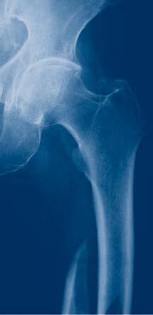


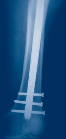


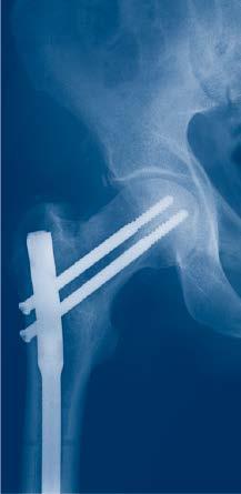

8 Preoperative Follow-up (1 month after surgery) Preoperative Follow-up (1 month after surgery) Titanium Cannulated Lateral Entry Femoral Recon Nail Expert System Technique Guide Synthes 7
9 Preoperative Planning Use the AO preoperative planner template for the expert titanium cannulated lateral entry femoral recon nail to estimate nail diameter and length. To estimate nail diameter, place the template on the AP or lateral x-ray of the uninjured femur and measure the diameter of the medullary canal at the narrowest part that will contain the nail. To estimate nail length, place the template on the AP x-ray of the uninjured femur and select the appropriate nail length based on patient anatomy. When selecting nail size, consider canal diameter, fracture pattern, patient anatomy and postoperative protocol. Note: Templates are available in two sizes: actual size and 115% magnification in which the image is enlarged 15% to correspond to typical radiographic magnification; however, variations in magnification levels are common. 8 Synthes Titanium Cannulated Lateral Entry Femoral Recon Nail Expert System Technique Guide


10 1 Position patient Position the patient in the lateral decubitus or supine position on a fracture table or radiolucent operating table. Position the C-arm to allow visualization of the proximal femur in both the AP and lateral planes. To facilitate access to the medullary canal, abduct the upper part of the body approximately to the contralateral side and adduct the affected limb by Affected leg adduction 2 Reduce fracture Instrument * Large Distractor Perform closed reduction manually by axial traction under image intensifier control. The use of the large distractor or other reduction instrumentation may be appropriate in certain circumstances. *Also available Titanium Cannulated Lateral Entry Femoral Recon Nail Expert System Technique Guide Synthes 9


11 Preoperative Planning 3 Confirm nail length Instrument Radiographic Ruler, for Titanium Cannulated Femoral Nails The required nail length must be determined after reduction of the femoral fracture. Position the C-arm for an AP view of the proximal femur. With long forceps, hold the ruler alongside the lateral thigh, parallel to and at the same level as the femur. Adjust the ruler until the proximal end is at the desired nail insertion depth. Mark the skin at the proximal end of the ruler. Move the C-arm to the distal femur. Verify fracture reduction. Align the proximal end of the radiographic ruler to the skin mark, and take an AP image of the distal femur. Read nail length directly from the ruler image, selecting the measurement at or just proximal to the epiphyseal scar, or at the chosen insertion depth. Notes: It is recommended that all fractures be treated with the longest nail possible, taking into account patient anatomy or a previous implant. Back-hammering or dynamization to close a fracture gap must be taken into account when determining the nail length. A shorter nail should be chosen when backhammering or dynamization is planned. The dynamic slot allows 7 mm of movement. 10 Synthes Titanium Cannulated Lateral Entry Femoral Recon Nail Expert System Technique Guide
12 4 Confirm nail diameter Instrument Radiographic Canal Width Estimator Position the C-arm for an AP or lateral view of the femur at the level of the isthmus. Hold the radiographic canal width estimator over the femur so that the diameter gauge is centered over the narrowest part of the medullary canal. Read the estimated diameter measurement on the circular indicator that fills the canal. Note: If the reamed technique is used, the diameter of the largest medullary reamer must be a minimum of 1.0 mm larger than the nail diameter. Titanium Cannulated Lateral Entry Femoral Recon Nail Expert System Technique Guide Synthes 11


13 Opening the Femur 1 Approach Palpate the posterior edge of the greater trochanter. Make a 3 cm incision in line with the central axis of the intramedullary canal in the lateral view, and depending on the anatomy of the patient, 2 5 cm proximal to the tip of the greater trochanter. 2 Determine entry point 10 The insertion point for the nail is approximately 20 mm lateral to the center of the medullary canal. The insertion point is 10 lateral to the greater trochanter, as measured from a point 40 mm distal to the lesser trochanter. The entry point can also be described as lateral to the greater trochanter at the same level as the superior aspect of the base of the femoral neck (just above the piriformis fossa). This point can be found by extending a line horizontally from the base of the femoral neck to the lateral side of the femur. 40 mm 12 Synthes Titanium Cannulated Lateral Entry Femoral Recon Nail Expert System Technique Guide

14 3 Insert guide wire Instruments mm Guide Wire, 290 mm Handle for Wire Guides/ Protection Sleeves mm Protection Sleeve for Lateral Femoral Nails Wire Guide for 17 mm Protection Sleeve for Lateral Femoral Nails Assemble the handle, protection sleeve and wire guide. Insert the assembly through the incision to the bone. Hold the protection sleeve firmly and insert the guide wire through the central hole in the wire guide. The guide wire must be inserted laterally at an angle of 10 to the center of the medullary canal. The tip of the guide wire should be centered in the medullary canal 40 mm distal to the lesser trochanter. Verify that the guide wire position allows adequate clearance on the lateral side of the femur for the opening drill bit. The guide wire is inserted with it centered in the lateral view. If the position of the initial wire must be altered, adjust wire guide to the desired position and insert a second guide wire into guide. Remove the first wire and wire guide. Alternative instrument * 8.0 mm Cannulated Curved Awl In place of a guide wire, the medullary canal can be initially opened with the curved awl. After opening the canal, insert a reaming rod through the curved awl. *Also available Titanium Cannulated Lateral Entry Femoral Recon Nail Expert System Technique Guide Synthes 13


15 Opening the Femur 4 Open medullary canal with drill bit and flexible reamers Instruments mm Cannulated Drill Bit mm Cannulated Drill Bit Handle for Wire Guides/ Protection Sleeves 20 mm mm Protection Sleeve for Lateral Femoral Nails Drill Select appropriate cannulated drill bit as follows: Nail Diameter Drill Bit Size 9.0 mm 12.0 mm 15.0 mm 13.0 mm 16.0 mm 17.0 mm Drill through the protection sleeve. Drill the medullary canal to a depth of 20 mm. Remove the guide wire, drill bit and protection sleeve. Note: Dispose of the guide wire. Do not reuse. Ream Proceed to page 17 for the section on reaming. Place the 2.5 mm reaming rod and ream the medullary canal to the desired diameter. Open Open the proximal femur to a depth of 80 mm using the flexible reamers as follows: Nail Diameter Proximal Reamer Diameter 9.0 mm 12.0 mm 15.0 mm 13.0 mm 16.0 mm 17.0 mm 14 Synthes Titanium Cannulated Lateral Entry Femoral Recon Nail Expert System Technique Guide

16 Alternative techniques: Open medullary canal with cannulated drill bits Instruments mm Cannulated Drill Bit mm Cannulated Drill Bit Handle for Wire Guides/ Protection Sleeves mm Protection Sleeve for Lateral Femoral Nails Using the protection sleeve and cannulated drill bit, drill over the 3.2 mm guide wire until the drill stop on the drill reaches the protection sleeve. Monitor progress of the drill with the image intensifier. Ensure that the lateral and medial cortical walls are not compromised. Adjust the guide wire if necessary. Remove the guide wire, protection sleeve and drill bit. Note: Dispose of the guide wire. Do not reuse. Alternative instruments * 15.0 mm Cannulated Flexible Drill Bit, large quick coupling * 17.0 mm Cannulated Flexible Drill Bit, large quick coupling Insert the guide wire approximately 20 mm into the proximal femur. Using the cannulated flexible drill bit, ream to the level of the lesser trochanter. Remove the guide wire and drill bit. Note: Dispose of the guide wire. Do not reuse. *Also available Titanium Cannulated Lateral Entry Femoral Recon Nail Expert System Technique Guide Synthes 15

17 Opening the Femur Open medullary canal with awl Instruments mm Cannulated Awl mm Guide Wire, 400 mm Place the cannulated awl over the guide wire and open the medullary canal. Use a twisting motion to advance the awl to a depth of approximately 80 mm. Remove the guide wire and awl. Note: Dispose of the guide wire. Do not reuse. 16 Synthes Titanium Cannulated Lateral Entry Femoral Recon Nail Expert System Technique Guide
18 Alternative Techniques Opening the Femur 5 Ream medullary canal (optional) Required set Flexible Reamer Set for IM Nails Alternative set Reamer/ Irrigator /Aspirator Instrument Set Instruments * Holding Device, for Guide Wires and Reaming Rods Reaming Rod Push Rod S* S* S* 2.5 mm Reaming Rod with ball tip, 950 mm 2.5 mm Reaming Rod with ball tip and extension, 950 mm 2.5 mm Reaming Rod with ball tip, 1150 mm * Holding Forceps for Reaming Rods mm Intramedullary Reduction Tool * Small Universal T-Handle Chuck If necessary, enlarge the femoral canal with the medullary reamer to the desired diameter. Check fracture reduction under image intensifier. *Also available Titanium Cannulated Lateral Entry Femoral Recon Nail Expert System Technique Guide Synthes 17


.")
19 Alternative Techniques Opening the Femur Insert reaming rod Insert the reaming rod with ball tip into the medullary canal, using the holding device or T-handle chuck, to the desired insertion depth. If using the holding device, set thumb switch to the RELEASE or LOCK position (Figure 1). Insert guide wire/reaming rod. Apply force to the lever with your hand as far from the pivot as possible (Figure 2). RELEASE position: Clamp will free the wire upon releasing the handle. LOCK position: Clamp will retain the wire. The device will click when set to the LOCK position. Note: To release a wire retained in the LOCK position, apply force to the lever on its lower end, then push the thumb switch to the RELEASE position. This relaxes the engagement of the locking mechanism by deflecting the lever (Figure 3). To bend reaming rods, insert extension tip into reaming rod hole on the back of the handle. Bend until the rod contacts the handle. This allows a 15º bend on the reaming rod tip (Figure 4). Figure 1 Figure 2 Figure 3 Figure 4 18 Synthes Titanium Cannulated Lateral Entry Femoral Recon Nail Expert System Technique Guide


20 Reaming Starting with the 8.5 mm diameter reaming head, ream to a diameter a minimum of 1.0 mm greater than the nail diameter. Ream in 0.5 mm increments and advance the reamer with steady, moderate pressure. Do not force the reamer. Partially retract the reamer often to clear debris from the medullary canal. The holding forceps can be used to control the rotation of the reaming rod. Note: The reaming rod with ball tip can be removed through all cannulated lateral entry femoral nails. Reaming rod exchange is not required. Option: Use the reaming rod push rod to help retain the reaming rod during reamer extraction. Titanium Cannulated Lateral Entry Femoral Recon Nail Expert System Technique Guide Synthes 19
21 Inserting the Nail 1 Assemble insertion instruments Instruments Cannulated Connecting Screw, for 100 mm Insertion Handle Radiolucent Standard Insertion Handle for Expert Nails, 100 mm T-Handle Ball Hex Screwdriver, 8 mm Match the tang on the handle to the notch in the Titanium Cannulated Lateral Entry Femoral Recon Nail EX. Place the connecting screw into the insertion handle and thread it into the proximal nail end using the 8 mm ball hex screwdriver. The recon nails are labeled left or right on the proximal nail end. 20 Synthes Titanium Cannulated Lateral Entry Femoral Recon Nail Expert System Technique Guide


22 Alternative instruments Reaming Rod Push Rod * Radiolucent Percutaneous Insertion Handle for Expert Nails, 175 mm * Cannulated Connecting Screw, for 175 mm Percutaneous Insertion Handle Optionally, slide the connecting screw onto the reaming rod push rod. Slide the assembly through the insertion handle and match the tang on the handle to the nail. Tighten using the hex on the reaming rod push rod. Secure the assembly using the 8 mm ball hex screwdriver. *Also available Titanium Cannulated Lateral Entry Femoral Recon Nail Expert System Technique Guide Synthes 21


23 Inserting the Nail 2 Insert nail Instruments Hammer Guide Spiral Combination Hammer, 500 grams Driving Cap, threaded mm Pin Wrench mm Ratchet Wrench Cannulated Shaft with 8 mm hex Thread the driving cap into the insertion handle and secure it using the 11 mm ratchet wrench. If patient anatomy allows, thread the driving cap in the medial position. If necessary, the hammer guide can be threaded onto the driving cap and the hammer can be used as a slide hammer. Orient the insertion handle in an anterior position. Use the C-arm to verify fracture reduction. Insert the nail as far as possible. The nail rotates approximately 90 during insertion. The insertion handle rotates from an anterior to a lateral position during insertion of the last one-third of the nail length. If the nail does not rotate to the lateral position, remove the nail and reinsert with the handle slightly lateral to the sagittal plane. Monitor nail passage across the fracture, and control in two planes to avoid malalignment. Note: Do not mount the aiming arm until the nail has been completely inserted. If desired, insert the nail using light hammer blows. Note: If nail insertion is difficult, choose a smaller diameter nail or ream the intramedullary canal to a larger diameter. Important: Do not strike the insertion handle directly. 22 Synthes Titanium Cannulated Lateral Entry Femoral Recon Nail Expert System Technique Guide

24 3 Check proximal nail position Insert the nail until it is at or below the femoral opening. Check final nail position under image intensification in AP and lateral views. If primary compression or secondary dynamization are planned, it is recommended to overinsert the nail by more than 7 mm, which corresponds to the maximum distance between the positions in static and dynamic modes. Note: The distance between the markings on the insertion handle is 5 mm and corresponds to the extensions of the end caps. This feature can be used for overinsertion of the nail. 4 Check distal nail location Use image intensification to ensure the nail is centered in both AP and lateral views. Verify fracture alignment. Remove the reaming rod. Titanium Cannulated Lateral Entry Femoral Recon Nail Expert System Technique Guide Synthes 23


25 Locking Options Proximal locking with 120 locking screw and dynamic locking option Proximal locking with static locking option Proximal locking with two recon screws 24 Synthes Titanium Cannulated Lateral Entry Femoral Recon Nail Expert System Technique Guide
26 Proximal Locking 1 Choose appropriate locking screws and instruments Use the correct locking screw, drill sleeve, trocar and drill bit for the selected nail diameter, as shown on the table. Nail Diameter Locking Screws Protection Sleeve Drill Sleeve Trocar Calibrated Drill Bit 9.0 mm 5.0 mm 12.0 mm/8.0 mm 8.0 mm/4.2 mm 4.2 mm 4.2 mm 13.0 mm (green) ( ) ( ) ( ) ( ) (green) 14.0 mm 6.0 mm 12.0 mm/8.0 mm 8.0 mm/5.0 mm 5.0 mm 5.0 mm 16.0 mm (aqua) ( ) ( ) ( ) ( ) (aqua) For standard locking, three targeted proximal locking options are possible: antegrade locking 2 Dynamic locking (LM) 3 Static locking (LM) 1 For immediate dynamization, insert one proximal locking screw through the dynamic slot. If dynamization may be required in the future, use the dynamic locking option with the 120 antegrade locking hole. 2 3 Titanium Cannulated Lateral Entry Femoral Recon Nail Expert System Technique Guide Synthes 25
27 Proximal Locking 2 Connect aiming arm Instrument Radiolucent Aiming Arm for Lateral Entry Femoral Nail EX T-Handle Ball Hex Screwdriver, 8 mm Confirm that the nail is securely connected to the insertion handle using the 8 mm ball hex screwdriver. Mount the aiming arm to the insertion handle. 26 Synthes Titanium Cannulated Lateral Entry Femoral Recon Nail Expert System Technique Guide
 and insert it through the desired LM hole in the aiming arm.")
28 3 Insert trocar combination Instruments mm/ 8.0 mm Protection Sleeve, 188 mm mm/4.2 mm Drill Sleeve mm/5.0 mm Drill Sleeve mm Trocar mm Trocar Assemble the three-part trocar combination (protection sleeve, drill sleeve and trocar) and insert it through the desired LM hole in the aiming arm. The cam lock lever must be in the unlocked position to insert the assembly. Make a stab incision and insert the trocar to the bone. Remove the trocar. Alternative instrument Scalpel Handle, long The scalpel handle may be used through the aiming arm for precise placement of the incision. If using the 120 antegrade locking option, insert the trocar combination through the hole labeled 120 on the insertion handle. Note: Do not exert forces on the aiming arm, protection sleeve, drill sleeves and drill bits. These forces may prevent accurate targeting through the proximal locking holes and damage the drill bits. Titanium Cannulated Lateral Entry Femoral Recon Nail Expert System Technique Guide Synthes 27


29 Proximal Locking 4 Drill and measure for locking screw length Instruments mm Three-Fluted Drill Bit, quick coupling, 330 mm, 100 mm calibration mm Three-Fluted Drill Bit, quick coupling, 330 mm, 100 mm calibration Ensure that the drill sleeve is pressed firmly to the lateral cortex. Using the appropriate drill bit (4.2 mm for 5.0 mm locking screws or 5.0 mm for 6.0 mm locking screws), drill through both cortices until the tip of the drill bit just penetrates the far cortex. Confirm drill bit position. Ensure that the drill sleeve is pressed firmly to the lateral cortex and read the measurement from the calibrated drill bit at the back of the drill sleeve. This measurement corresponds to the appropriate length locking screw. Remove the drill bit and the drill sleeve. Ensure that the protection sleeve is pressed firmly to the near cortex and depress the cam lock lever to lock the protection sleeve in position. Alternative instruments Depth Gauge, for Locking Screws to 100 mm or * Depth Gauge, for Locking Screws After drilling both cortices, remove the drill bit and the drill sleeve. * Also available 28 Synthes Titanium Cannulated Lateral Entry Femoral Recon Nail Expert System Technique Guide
30 Disassemble the depth gauge into two parts: the outer sleeve and the measuring device with hook. Insert the measuring device into the protection sleeve. Make sure that the hook grasps the far cortex. Confirm depth gauge position in the far cortex of the femur. Read the measurement from the back of the protection sleeve, to determine the appropriate length locking screw. Titanium Cannulated Lateral Entry Femoral Recon Nail Expert System Technique Guide Synthes 29


31 Proximal Locking 5 Insert locking screw Instrument StarDrive Screwdriver, T25, self-retaining, 320 mm Insert the appropriate length locking screw through the protection sleeve using the Star/HexDrive screwdriver. Verify locking screw length under image intensification. The tip of the locking screw should not project more than 2 mm to 4 mm beyond the far cortex. Note: A groove on the screwdriver provides a rough indication that the locking screw is fully inserted through the sleeve. Repeat for the second proximal locking screw if desired. Alternative technique Instrument * Inter-lock Screwdriver, T25, 3.5 mm Hex, 330 mm Ensure that the slider of the screwdriver is fully retracted. Seat the inter-lock screwdriver tip in the appropriate length screwhead recess. Turn the nut clockwise until the tip of the slider is fully wedged into the screwhead recess. Always use the standard screwdriver for final tightening of the screw. To disengage the screw from the screwdriver, turn the nut counter-clockwise until the slider is ejected from the screwhead recess. * Also available 30 Synthes Titanium Cannulated Lateral Entry Femoral Recon Nail Expert System Technique Guide


32 Proximal Locking Recon 1 Confirm nail position In the AP view, adjust the nail insertion depth to ensure that the two recon screws can be placed into the femoral head. Adjust nail position for correct anteversion. 2 Connect aiming arm Instrument Radiolucent Aiming Arm for Lateral Entry Femoral Nail EX T-Handle Ball Hex Screwdriver, 8 mm Confirm that the nail is securely connected to the insertion handle using the 8 mm ball hex screwdriver. Mount the aiming arm to the insertion handle. Titanium Cannulated Lateral Entry Femoral Recon Nail Expert System Technique Guide Synthes 31


33 Proximal Locking Recon 3 Insert guide wires for recon screws Instruments mm/8.5 mm Protection Sleeve, for Recon Locking mm/3.2 mm Wire Guide, for Recon Locking mm Trocar, for Recon Locking mm Guide Wire, 400 mm Assemble both three-part trocar combination (protection sleeve, drill sleeve and trocar) and insert it through the desired LM recon holes in the aiming arm. The cam lock lever must be in the unlocked position to insert the assembly. Make a stab incision and insert the trocar to the bone. Remove the inferior trocar. Alternative Instrument Scalpel Handle, long The scalpel handle may be used through the aiming arm for precise placement of the incision. Insert a guide wire into the femoral head approximately 5 mm from subchondral bone. Check guide wire placement radiographically in both AP and lateral views. Remove the superior trocar. Insert the second guide wire into the femoral head approximately 5 mm from subchondral bone. Check the guide wire placement in both AP and lateral views. Note: Do not exert forces on the aiming arm, protection sleeves, and drill sleeves. These forces may prevent accurate targeting through the locking holes. 32 Synthes Titanium Cannulated Lateral Entry Femoral Recon Nail Expert System Technique Guide

34 4 Determine length and drill for inferior recon screw Instruments Drill Bit for 6.0 mm Recon Screws Drill Stop, for 4.5 mm/6.5 mm Stepped Drill Bit Specialty Locking Measuring Device or * Specialty Locking Measuring Device Measure for the inferior screw. Ensure that the protection sleeve is pressed firmly to the near cortex and depress the cam lock lever to lock the protection sleeve in position. Remove the wire guide and insert the specialty locking measuring device over the guide wire, into the protection sleeve, and to the bone. Read the length of the required recon screw directly on the measuring device. Remove the measuring device and the inferior guide wire. Attach the drill stop to the stepped drill bit for the appropriate length screw. Guide the stepped drill bit through the protection sleeve to the bone. Drill to the stop. * Also available Titanium Cannulated Lateral Entry Femoral Recon Nail Expert System Technique Guide Synthes 33

35 Proximal Locking Recon 5 Insert inferior recon screw Instrument StarDrive Screwdriver, T25, self-retaining, 440 mm Insert the appropriate recon screw through the protection sleeve into the femoral head, using the long T25 StarDrive screwdriver. Verify the position of the locking screw under image intensification in both planes. A groove on the screwdriver indicates when the recon screw is fully inserted. Repeat steps 3 through 5 for the second, superior recon screw. 34 Synthes Titanium Cannulated Lateral Entry Femoral Recon Nail Expert System Technique Guide
 (03.010.")
36 Distal Locking 1 Distal locking There are three distal locking options: Two transverse, lateral to medial holes One oblique locking hole for enhanced stability of distal fractures Nail Diameter Locking Screws Drill Bit 9.0 mm 5.0 mm 4.2 mm 13.0 mm (green) ( ) (green) or ( ) 14.0 mm 6.0 mm 5.0 mm 16.0 mm (aqua) ( ) (aqua) or ( ) If using the oblique locking hole, insert at least one transverse LM screw prior to rotating the leg for the oblique locking hole. This will maintain rotational alignment. Titanium Cannulated Lateral Entry Femoral Recon Nail Expert System Technique Guide Synthes 35

37 Distal Locking 2 Align image Check the reduction and correct alignment of the fragments and leg length before locking the nail. Align the C-arm with the hole in the nail closest to the fracture until a perfect circle is visible in the center of the screen. 3 Determine incision point Place a scalpel blade on the skin over the center of the hole to mark the incision point and make a stab incision. 36 Synthes Titanium Cannulated Lateral Entry Femoral Recon Nail Expert System Technique Guide
38 4 Drill Instruments * 4.2 mm Three-Fluted Drill Bit, quick coupling, 145 mm, for Radiolucent Drive * 5.0 mm Three-Fluted Drill Bit, quick coupling, 145 mm, for Radiolucent Drive Using the radiolucent drive under image intensification, insert the tip of the appropriate drill bit through the incision and down to the bone. Incline the drive so that the tip of the drill bit is centered over the locking hole. The drill bit should almost completely fill the circle of the locking hole. Hold the drill bit in this position and drill through both cortices. Tip: For greater drill bit control, discontinue drill power after perforating the near cortex. Manually guide the drill bit through the nail before resuming power to drill the far cortex. Alternative instruments mm Three-Fluted Drill Bit, quick coupling, 145 mm mm Three-Fluted Drill Bit, quick coupling, 145 mm If there is no radiolucent drive available and locking is performed with the standard freehand technique, use the 4.2 mm or 5.0 mm three-fluted drill bit, quick coupling. * Also available Titanium Cannulated Lateral Entry Femoral Recon Nail Expert System Technique Guide Synthes 37


39 Distal Locking 5 Determine length of locking screw Instruments * 4.2 mm Three-Fluted Drill Bit, quick coupling, 145 mm, for Radiolucent Drive * 5.0 mm Three-Fluted Drill Bit, quick coupling, 145 mm, for Radiolucent Drive mm Three-Fluted Drill Bit, quick coupling, 145 mm mm Three-Fluted Drill Bit, quick coupling, 145 mm Direct Measuring Device, for Locking Screws to 100 mm for IM Nails or * Direct Measuring Device, for Locking Screws to 100 mm, for IM Nails Stop drilling immediately after penetrating the far cortex. Disassemble the power drive or radiolucent drive from the drill bit. Ensure the correct position of the drill bit in regard to the far cortex of the femur. Place the direct measuring device onto the drill bit. Read the graduation of the measuring device at the end of the drill bit. This corresponds to the appropriate locking screw length. Note: Drill bit location with respect to the far cortex is critical for measuring the appropriate locking screw length. * Also available 38 Synthes Titanium Cannulated Lateral Entry Femoral Recon Nail Expert System Technique Guide

40 Alternative instruments Depth Gauge, for Locking Screws to 100 mm or * Depth Gauge, for Locking Screws to 100 mm, for IM Nails Depth Gauge for Distal Locking Screws, 100 mm Measure the locking screw length using the depth gauge for locking screws. Ensure the outer sleeve is in contact with the bone and the hook grasps the far cortex. Read the locking screw length directly from the depth gauge at the back of the outer sleeve or on the gauge. * Also available Titanium Cannulated Lateral Entry Femoral Recon Nail Expert System Technique Guide Synthes 39
41 Distal Locking 6 Insert locking screw a Instruments * Holding Sleeve with Locking Device StarDrive Screwdriver, T25, self-retaining, 320 mm b Insert the appropriate length locking screw using the T25 StarDrive screwdriver and the holding sleeve with locking device, if needed. Verify locking screw length under image intensification. If needed, a second locking screw may be inserted using the same technique. c Repeat Steps 2 to 6 for the remaining locking screws. Use the holding sleeve as described below: a Insert the holding sleeve onto the shaft of the screwdriver and place the tip of the screwdriver in the recess of the locking screw. Push the holding sleeve in the direction of the locking screw, the sleeve now holds the locking screw. b Lock the holding sleeve by tightening it counterclockwise. c Release the holding sleeve after insertion of the locking screw, by loosening it clockwise and pushing backward. * Also available 40 Synthes Titanium Cannulated Lateral Entry Femoral Recon Nail Expert System Technique Guide

42 Alternative technique Instrument * Inter-lock Screwdriver, T25, 3.5 mm Hex, 224 mm Ensure that the slider of the screwdriver is fully retracted. Seat the inter-lock screwdriver tip in the appropriate length screwhead recess. Turn the nut clockwise until the tip of the slider is fully wedged into the screwhead recess. Always use the standard screwdriver for final tightening of the screw. To disengage the screw from the screwdriver, turn the nut counter-clockwise until the slider is ejected from the screwhead recess. * Also available Titanium Cannulated Lateral Entry Femoral Recon Nail Expert System Technique Guide Synthes 41
43 End Cap Insertion 1 Insert end cap Instruments Cannulated StarDrive Screwdriver, T40, self-retaining, 277 mm Alternative instrument * Inter-lock Screwdriver, T40, 377 mm The end caps for femoral nails are available in extension lengths of 0 mm, 5 mm, 10 mm, 15 mm, and 20 mm. End caps fulfill two functions: preventing bone ingrowth into the nail and extending the nail height if it is overinserted. The end caps are cannulated for use over a guide wire, if necessary. Remove the nail insertion instruments. Optionally, for insertion of the 0 mm end cap, remove the connecting screw only. The insertion handle can remain to help align the end cap to the top of the nail. The 0 mm end cap fits through the barrel of the insertion handle. Insert the guide wire into the proximal end of the nail. Engage the end cap with the cannulated screwdriver by exerting axial pressure, or attach to the T40 inter-lock screwdriver. To prevent cross-threading, align the end cap with the nai axis and turn the end cap counterclockwise, until the thread of the end cap aligns with that of the nail. Turn the end cap clockwise to thread the end cap into the nail. Remove the guide wire and screwdriver. Always use the standard screwdriver for final tightening of the endcap. Note: The use of an end cap is recommended. The end cap protects the nail connection threads from bone ingrowth to facilitate removal, and extends the nail height if the nail is overinserted. * Also available 42 Synthes Titanium Cannulated Lateral Entry Femoral Recon Nail Expert System Technique Guide

44 Implant Removal 1 Remove end cap and locking screws Instruments StarDrive Screwdriver, T25, self-retaining, 320 mm Cannulated StarDrive Screwdriver, T40, self-retaining, 277 mm mm Guide Wire Implant removal is an optional procedure. Clear the StarDrive recess of the end cap and the locking implants of any ingrown tissue. Insert the guide wire for easy alignment of the screwdriver in the cannulated end cap. Remove the end cap using the T40 screwdriver. Remove all locking screws except one proximal locking screw. Alternative instruments * Cannulated StarDrive Screwdriver, T40, with lever handle, self-retaining * Holding Sleeve, with Locking Device * Inter-lock Screwdriver, T40, 377 mm Alternatively, the T40 inter-lock screwdriver, or the cannulated StarDrive screwdriver, T40, with lever handle may be used with the 11 mm ratchet wrench to remove the end cap. Important: When removing implants after long-term implantation, especially in the presence of large amounts of bony ingrowth, first use a solid screwdriver to loosen the end cap. The inter-lock screwdriver can be used to remove the end cap from the surgical sight. * Also available Titanium Cannulated Lateral Entry Femoral Recon Nail Expert System Technique Guide Synthes 43

45 Implant Removal 2 Attach extraction screw and hammer guide Instruments Hammer Guide, for Slide Hammer Extraction Screw Before removing the final locking screw, screw the extraction screw into the nail and tighten it. The locking screw will prevent nail rotation as the extraction screw is tightened. Attach the hammer guide to the extraction screw. Remove the remaining locking screw with the screwdriver. 44 Synthes Titanium Cannulated Lateral Entry Femoral Recon Nail Expert System Technique Guide

46 3 Remove nail Instrument Spiral Combination Hammer, 500 grams Extract the nail by applying gentle blows with the hammer. Note: The nail will rotate about 90, similar to the movement during the insertion. Titanium Cannulated Lateral Entry Femoral Recon Nail Expert System Technique Guide Synthes 45

47 Implant Removal Alternative technique extraction hook For removal of broken nail Instruments * Extraction Hook, for Titanium Cannulated Nails Universal Chuck with T-Handle or * Small Universal Chuck with T-Handle 1 Clear tissue from the end of the nail and remove the end cap. 2 Remove the locking bolts and/or screws with the appropriate screwdriver. 3 Insert the extraction hook into the universal chuck with T-handle. The hook should be parallel with the T-handle. This facilitates visualization of the hook position in the bone. * Also available Available nonsterile or sterile-packed. Add S to product number to indicate sterile product. 46 Synthes Titanium Cannulated Lateral Entry Femoral Recon Nail Expert System Technique Guide

48 4 Attach appropriate extraction bolt or connecting screw to the nail. Remove the near nail fragment using the extraction the bolt or connecting screw. Note: The extraction hook can be used as an alternative to extraction instrumentation. 5 Ream the medullary canal 1 mm larger than the diameter to clear a path for the distant nail fragment. 6 Insert the extraction hook and explanted, near nail fragment into the medullary canal. The near nail fragment aligns the extraction hook with the cannulation of the distant nail fragment. 7 Pass the extraction hook through the cannula of the distant nail fragment. Note: Under image intensification, verify that the hook has passed through and engaged the distant end of the nail. 8 Extract both nail fragments. Note: Keep the patient s limb restrained to increase the efficiency of the extraction force. Titanium Cannulated Lateral Entry Femoral Recon Nail Expert System Technique Guide Synthes 47
49 Implant Removal For removal of an intact nail Instruments * Extraction Hook, for Titanium Cannulated Nails Universal Chuck with T-Handle or * Small Universal Chuck with T-Handle 1 Clear tissue from the end of the nail and remove the end cap. 2 Remove the locking bolts and/or screws with the appropriate screwdriver. 3 Insert the extraction hook into the universal chuck with T-handle. The hook should be parallel with the T-handle. This facilitates visualization of the hook position in the bone. 4 Insert the extraction hook through the nail cannula. Note: Under image intensification, verify that the hook has passed through and engaged the distant end of the nail. 5 Extract the nail. Note: Keep the patient s limb restrained to increase the efficiency of the extraction force. * Also available Available nonsterile or sterile-packed. Add S to product number to indicate sterile product. 48 Synthes Titanium Cannulated Lateral Entry Femoral Recon Nail Expert System Technique Guide
50 Implant Specifications Lateral Entry Femoral Recon Nail EX Available for left or right femur Anatomic nail design based on a femoral canal tracing study 3 Material Titanium-6% aluminum-7% niobium alloy 120 antegrade Recon locking Dynamic transverse Static transverse 20.6 mm 47 mm 60.6 mm 13 mm 7 mm Diameters 9.0 mm to 16.0 mm, cannulated 9.0 mm through 12.0 mm nails 13.5 mm proximal diameter 13.0 mm through 16.0 mm nails 16.0 mm proximal diameter Colors 9.0 mm through 13.0 mm (light green) 14.0 mm through 16.0 mm (aqua) Lengths 300 mm through 480 mm in 20 mm increments Cross Section 9.0 mm through 16.0 mm diameter nails helical fluted Proximal Locking Two recon locking holes (130 neck/shaft angle) Dynamization slot (LM) Static transverse locking hole (LM) 120 antegrade locking hole Distal Locking Two transverse locking holes (LM) One oblique locking hole (LM) LM Oblique LM 12 mm 27 mm 42 mm 3. L.Ehmke, et al. Titanium Cannulated Lateral Entry Femoral Recon Nail Expert System Technique Guide Synthes 49
51 Implants Titanium Cannulated Lateral Entry Femoral Recon Nails EX, sterile (green) Length 9 mm dia. 9 mm dia. (mm) right left S S S S S S S S S S S S S S S S S S S S Length 10 mm dia. 10 mm dia. (mm) right left S S S S S S S S S S S S S S S S S S S S Length 11 mm dia. 11 mm dia. mm) right left S S S S S S S S S S S S S S S S S S S S Length 12 mm dia. 12 mm dia. (mm) right left S S S S S S S S S S S S S S S S S S S S Length 13 mm dia. 13 mm dia. (mm) right left S S S S S S S S S S S S S S S S S S S S 50 Synthes Titanium Cannulated Lateral Entry Femoral Recon Nail Expert System Technique Guide
52 Titanium Cannulated Lateral Entry Femoral Recon Nails EX, sterile (aqua) Length 14 mm dia. 14 mm dia. (mm) right left S S S S S S S S S S S S S S S S S S S S Length 15 mm dia. 15 mm dia. (mm) right left S S S S S S S S S S S S S S S S S S S S Length 16 mm dia. 16 mm dia. (mm) right left S S S S S S S S S S S S S S S S S S S S Titanium Cannulated Lateral Entry Femoral Recon Nail Expert System Technique Guide Synthes 51
 Length (mm) 04.005.516 26 04.005.548 58 04.")
53 Implants 5.0 mm Titanium Locking Screws, with T25 StarDrive recess, for IM Nails (light green) Titanium alloy* Lengths: 26 mm 80 mm (2 mm increments) 85 mm 100 mm (5 mm increments) 4.3 mm core diameter Fully threaded Self-tapping, blunt tip T25 StarDrive recess for improved torque transmission and self-retention on screwdriver Length (mm) Length (mm) Available nonsterile or sterile-packed. Add S to product number to indicate sterile product. * Titanium-6% aluminum-7% niobium alloy 52 Synthes Titanium Cannulated Lateral Entry Femoral Recon Nail Expert System Technique Guide
54 6.0 mm Titanium Locking Screws, with T25 StarDrive recess, for IM Nails (aqua) Titanium alloy* Lengths: 26 mm 60 mm (2 mm increments) 64 mm 80 mm (4 mm increments) 85 mm 100 mm (5 mm increments) 4.8 mm core diameter Self-tapping tip T25 StarDrive recess for improved torque transmission and self-retention on screwdriver. Length (mm) Length (mm) Available nonsterile or sterile-packed. Add S to product number to indicate sterile product. * Titanium-6% aluminum-7% niobium alloy Titanium Cannulated Lateral Entry Femoral Recon Nail Expert System Technique Guide Synthes 53
55 Implants 6.5 mm Titanium Recon Screws, with T25 StarDrive recess Titanium alloy* Lengths: 60 mm 130 mm (5 mm increments) Self-tapping tip T25 StarDrive recess for improved torque transmission and self-retention on screwdriver. Length (mm) Length (mm) Titanium End Caps, with T40 StarDrive recess, for Titanium Cannulated Lateral Entry Femoral Recon Nail EX Titanium alloy* Protect nail threads from tissue ingrowth Cannulated to allow insertion over a guide wire T40 StarDrive recess 20 mm 15 mm 10 mm 5 mm 0 mm 0 mm Sits flush with end of nail 5 mm, 10 mm 15 mm and 20 mm extensions Extend nail height if nail is overinserted End Cap, 0 mm extension 12 mm End Caps 16 mm End Caps for 9 mm for 13 mm 12 mm nails 16 mm nails mm extension mm extension mm extension mm extension Available nonsterile or sterile-packed. Add S to product number to indicate sterile product. * Titanium-6% aluminum-7% niobium alloy 54 Synthes Titanium Cannulated Lateral Entry Femoral Recon Nail Expert System Technique Guide
 ASLS screws, 30 mm 100 mm, are compatible with titanium cannulated lateral entry femoral recon nails in diameters 9 mm 13 mm 6.")
56 Additionally Available Implants Titanium Angular Stable Locking Screws, with T25 StarDrive recess, for intramedullary nails, sterile* Titanium alloy** 5.0 mm (light blue) ASLS screws, 30 mm 100 mm, are compatible with titanium cannulated lateral entry femoral recon nails in diameters 9 mm 13 mm 6.0 mm (dark purple) ASLS screws, 32 mm 125 mm, are compatible with titanium cannulated lateral entry femoral recon nails in diameters 14 mm 16 mm Fully threaded shaft with 3 diameters D1: Provides purchase in reamed near cortex D2: Expands sleeve, providing angular stability D3: Holds unexpanded sleeve for screw insertion, provides purchase in far cortex T25 StarDrive recess Sterile packaged D1 D2 D3 Note: For more information, please see ASLS technique guide and brochure. * Also available ** Titanium-6% aluminum-7% niobium alloy Titanium Cannulated Lateral Entry Femoral Recon Nail Expert System Technique Guide Synthes 55
 08.025.")
57 Implants ASLS Sleeves* Resorbable Sleeves for Angular Stable Locking Screws, sterile* 70:30 poly(l/ DL-lactide) Bioresorbable polymer material gradually resorbs within months 1 Inner thread for secure fit to ASLS screw Expands in nail s locking hole to provide angular stability 5.0 mm and 6.0 mm sleeves used with corresponding ASLS screws Sterile packaged (2 per package) S S Resorbable Sleeve for Angular Stable Locking Screws, sterile, 2/pkg. for 5.0 mm ASLS Screws for 6.0 mm ASLS Screws ASLS Compatibility with Existing Nails The Angular Stable Locking System is compatible with all Synthes titanium cannulated nailing systems. Angular Stable Locking Systems Nail 5.0 mm 6.0 mm Nailing System Diameters (mm) (light blue) (dark purple) Femur Titanium Cannulated 9 13 Lateral Entry Femoral Nail-EX Based on in-vivo animal testing. In-vivo animal testing may not necessarily be indicative of human clinical performance. * Must be ordered separately. 56 Synthes Titanium Cannulated Lateral Entry Femoral Recon Nail Expert System Technique Guide

58 Instruments Radiographic Ruler, for Titanium Cannulated Femoral Nails mm Cannulated Drill Bit, large quick coupling, 280 mm mm Cannulated Drill Bit, large quick coupling, 280 mm mm Cannulated Awl mm Three-Fluted Drill Bit, quick coupling, 330 mm, 100 mm calibration mm Three-Fluted Drill Bit, quick coupling, 330 mm, 100 mm calibration Available nonsterile or sterile-packed. Add S to product number to indicate sterile product. Titanium Cannulated Lateral Entry Femoral Recon Nail Expert System Technique Guide Synthes 57
59 Instruments mm/ 8.0 mm Protection Sleeve, 188 mm mm/ 4.2 mm Drill Sleeve, 200 mm mm/5.0 mm Drill Sleeve, 200 mm mm Trocar, 210 mm mm Trocar, 210 mm mm/8.5 mm Protection Sleeve for Recon Locking mm/3.2 mm Wire Guide for Recon Locking Available nonsterile or sterile-packed. Add S to product number to indicate sterile product. 58 Synthes Titanium Cannulated Lateral Entry Femoral Recon Nail Expert System Technique Guide

60 mm Trocar for Recon Locking Drill Stop, for 4.5 mm/6.5 mm Stepped Drill Bit mm/6.5 mm Stepped Drill Bit Large, quick coupling, 485 mm Tap for 6.5 mm Recon Screws mm Three-Fluted Drill Bit, quick coupling, needle point, 145 mm mm Three-Fluted Drill Bit, quick coupling, needle point, 145 mm Cannulated Connection Screw for 100 mm Insertion Handle Available nonsterile or sterile-packed. Add S to product number to indicate sterile product. Titanium Cannulated Lateral Entry Femoral Recon Nail Expert System Technique Guide Synthes 59


61 Instruments Star/ Hex Screwdriver Shaft, 165 mm Star/ Hex Screwdriver Shaft, 280 mm Spiral Hammer Guide Depth Gauge for Locking Screws to 100 mm for IM Nails Direct Measuring Device for Locking Screws to 100 mm for IM Nails Radiolucent Aiming Arm for Lateral Femoral Nails Available nonsterile or sterile-packed. Add S to product number to indicate sterile product. 60 Synthes Titanium Cannulated Lateral Entry Femoral Recon Nail Expert System Technique Guide


62 Radiolucent Standard Insertion Handle, 100 mm Scalpel Handle, long Specialty Locking Measuring Device for Titanium Femoral Nails EX Depth Gauge for Distal Locking Screws, 100 mm Handle for Wire Guide/ Protection Sleeves mm Protection Sleeve for Lateral Femoral Nails Available nonsterile or sterile-packed. Add S to product number to indicate sterile product. Titanium Cannulated Lateral Entry Femoral Recon Nail Expert System Technique Guide Synthes 61


63 Instruments Wire Guide for 17 mm Protection Sleeve for Lateral Femoral Nails StarDrive Screwdriver, T25, self-retaining, 250 mm Large Handle with Quick Coupling T-Handle Ball Hex Screwdriver, 8 mm StarDrive Screwdriver, T25, self-retaining, 320 mm StarDrive Screwdriver, T25, self-retaining, 440 mm Cannulated StarDrive Screwdriver, T40, self-retaining, 277 mm 62 Synthes Titanium Cannulated Lateral Entry Femoral Recon Nail Expert System Technique Guide


64 Combination Hammer, 500g Driving Cap with Handle Adapter T40 StarDrive Screwdriver Shaft mm Pin Wrench, 120 mm Ratchet Wrench, 11 mm width across flats Extraction Screw, for Titanium Femoral and Tibial Nails Cannulated Shaft with 8 mm hex, 125 mm mm Guide Wire, 400 mm Titanium Cannulated Lateral Entry Femoral Recon Nail Expert System Technique Guide Synthes 63
 Length (mm) 04.005.516 26 04.005.518 28 04.005.520 30 04.005.522 32 04.005.524 34 04.005.526 36 04.005.528 38 04.")
65 Lateral Entry Femoral Nail Recon EX Implant Set ( ) Rack Locking Screw/Spiral Blade Rack for Femoral Nail EX Implants Instrument Screw Forceps Implants 5.0 mm Titanium Locking Screws with T25 StarDrive recess, for IM Nails, 2 ea. Length (mm) Length (mm) mm Titanium Locking Screws with T25 StarDrive recess, for IM Nails, 2 ea. Length (mm) Length (mm) Available nonsterile or sterile-packed. Add S to product number to indicate sterile product. 64 Synthes Titanium Cannulated Lateral Entry Femoral Recon Nail Expert System Technique Guide
66 ASLS Screw Sets mm Angular Stable Locking System Screw Set 5.0 mm Titanium Angular Stable Locking Screws, with T25 StarDrive recess, for intramedullary nails, sterile, 2 ea. Length Length (mm) (mm) S S S S S S S S S S S S S S S S S S S S S S S S S S S S S S mm Angular Stable Locking System Screw Set 6.0 mm Titanium Angular Stable Locking Screws, with T25 StarDrive recess, for intramedullary nails, sterile, 2 ea. Length Length (mm) (mm) S S S S S S S S S S S S S S S S S S S S S S S S S S S S S S S S S S 125 ASLS Sleeves* S S Resorbable Sleeve for Angular Stable Locking Screws, sterile, 2/pkg. for 5.0 mm ASLS Screws for 6.0 mm ASLS Screws * Must be ordered separately. Titanium Cannulated Lateral Entry Femoral Recon Nail Expert System Technique Guide Synthes 65
67 Lateral Entry Femoral Nail Recon EX Instrument and Implant Set ( ) Implants continued 6.5 mm Titanium Recon Screws with T25 StarDrive recess, for IM Nails, 2 ea. Length (mm) Length (mm) Titanium End Cap, with T40 StarDrive, 0 mm extension, 2 ea. 12 mm Titanium End Caps, with T40 StarDrive, 2 ea mm extension mm extension mm extension mm extension 16 mm Titanium End Caps, with T40 StarDrive, 2 ea mm extension mm extension mm extension mm extension Available nonsterile or sterile-packed. Add S to product number to indicate sterile product. 66 Synthes Titanium Cannulated Lateral Entry Femoral Recon Nail Expert System Technique Guide

68 Titanium Cannulated Lateral Femoral Nail EX Opening Instrument Set ( ) Note: Opening, Insertion, and Locking Sets required for procedure. Graphic Case Tray 1 Level High, fully loaded weight 6.65 lbs Opening LFN Tray Label Sheet for LFN EX Opening Instrumentation Instruments Radiographic Ruler for Titanium Cannulated Femoral Nails Radiographic Canal Width Estimator mm Cannulated Drill Bit Large, quick coupling, 280 mm mm Cannulated Drill Bit Large, quick coupling, 280 mm mm Cannulated Awl Handle for Wire Guide/ Protection Sleeves mm Protection Sleeve for Lateral Femoral Nails Wire Guide for 17 mm Protection Sleeve for Lateral Femoral Nail mm Guide Wire, 400 mm, 10 ea. Graphic Cases Graphic Case, Full Length 1-High Graphic Case, Full Length 2-High Graphic Case, Full Length 3-High Graphic Case, Full Length 4-High For detailed cleaning and sterilization instructions, please refer to: In Canada, the cleaning and sterilization instructions will be provided with the Loaner shipments. Graphic Cases must be ordered separately, they are not part of set. Choose the graphic case necessary to hold selected set trays by height and weight restrictions Lifting Posts, 8 pack Titanium Cannulated Lateral Entry Femoral Recon Nail Expert System Technique Guide Synthes 67

69 Titanium Cannulated Lateral Femoral Nail EX Insertion Instrument Set ( ) Note: Opening, Insertion, and Locking Sets required for procedure. Graphic Case Tray 1.5 Level High,* fully loaded weight lbs LFN Insertion Tray Label Sheet for LFN EX Insertion Instrumentation Instruments mm Three-Fluted Drill Bit, quick coupling, 330 mm/100 mm calibration, 2 ea mm Three-Fluted Drill Bit, quick coupling, 330 mm/100 mm calibration, 2 ea mm/8.0 mm Protection Sleeve, 188 mm, 2 ea mm/4.2 mm Drill Sleeve, 200 mm, 2 ea mm/5.0 mm Drill Sleeve, 200 mm, 2 ea mm Trocar, 210 mm, 2 ea mm Trocar, 210 mm, 2 ea mm/8.5 mm Protection Sleeve for Recon Locking, 2 ea mm/3.2 mm Wire Guide for Recon Locking, 2 ea mm Trocar for Recon Locking, 2 ea mm/6.5 mm Stepped Drill Bit Large, quick coupling, 485 mm, 2 ea Drill Stop, for 4.5 mm/6.5 mm Stepped Drill Bit Tap for 6.5 mm Recon Screws mm Three-Fluted Drill Bit, quick coupling, needle point, 145 mm, 2 ea mm Three-Fluted Drill Bit, quick coupling, needle point, 145 mm, 2 ea Cannulated Connection Screw for 100 mm Insertion Handle, 2 ea Radiolucent Aiming Arm for Lateral Femoral Nails EX Radiolucent Standard Insertion Handle Specialty Locking Measuring Device for Titanium Femoral Nails EX T-Handle Ball Hex Screwdriver, 8 mm Driving Cap with Handle Adapter mm Guide Wire, 400 mm, 3 ea. Graphic Cases Graphic Case, Full Length 1-High Graphic Case, Full Length 2-High Graphic Case, Full Length 3-High Graphic Case, Full Length 4-High * Some graphic case trays are 1.5 levels high. If these trays are to be stored individually in a 2-High Graphic case, the lifting posts pack ( ) must be ordered. Graphic Cases must be ordered separately, they are not part of set. Choose the graphic case necessary to hold selected set trays by height and weight restrictions Lifting Posts, 8 pack 68 Synthes Titanium Cannulated Lateral Entry Femoral Recon Nail Expert System Technique Guide

70 Locking Instrument Set ( ) Note: Opening, Insertion, and Locking Sets required for procedure. Graphic Case Tray 1.5 Level High,* fully loaded weight Lbs Locking Tray Label Sheet for all EX Nail Locking Instrumentation Instruments Star/Hex Screwdriver Shaft, 165 mm Star/Hex Screwdriver Shaft, 280 mm Spiral Hammer Guide Depth Gauge for Locking Screws to 100 mm for IM Nails Direct Measuring Device for locking screws to 100 mm for IM Nails Scalpel Handle, long Depth Gauge for Distal Locking Screws, 100 mm StarDrive Screwdriver, T25, self-retaining, 250 mm Large Handle with quick coupling StarDrive Screwdriver, T25, self-retaining, 320 mm StarDrive Screwdriver, T25, self-retaining, 440 mm Cannulated StarDrive Screwdriver, T40, self-retaining, 277 mm Combination Hammer, 500g T40 StarDrive Screwdriver Shaft mm Pin Wrench, 120 mm, 2 ea Ratchet Wrench, 11 mm width across flats Extraction Screw for Titanium Nails Cannulated Shaft with 8 mm Hex, 125 mm Graphic Cases Graphic Case, Full Length 1-High Graphic Case, Full Length 2-High Graphic Case, Full Length 3-High Graphic Case, Full Length 4-High * Some graphic case trays are 1.5 levels high. If these trays are to be stored individually in a 2-High Graphic case, the lifting posts pack ( ) must be ordered. Graphic Cases must be ordered separately, they are not part of set. Choose the graphic case necessary to hold selected set trays by height and weight restrictions Lifting Posts, 8 pack Titanium Cannulated Lateral Entry Femoral Recon Nail Expert System Technique Guide Synthes 69

71 Reduction Instrument Set with MIPO ( ) Graphic Case Tray 1.5 Level High,* fully loaded weight lbs Reduction Tray Label Sheet for Reduction Instrumentation Instruments Reduction Finger Universal Quick Coupling T-Handle mm Guide Wire, 4 ea mm Self Drilling Schanz Screws, 250 mm, 2 ea mm Drill Bit Combination Wrench Reduction Handle, toothed, 2 ea Protection Sleeve, slotted mm/ 1.6 mm Wire Guide mm/ 5.0 mm Drill Sleeve Cannulated Tap for 5.0 mm Threaded Rod Adjusting Nut, 2 ea mm Threaded Rod, self-drilling tip, 2 ea mm Threaded Rod, blunt tip, 2 ea Large F-Tool mm IM Reduction Tool Large Combination Clamp, 2 ea Universal Chuck with T-Handle, 2 ea mm Carbon Fiber Rod, 350 mm Straight Ball Spike, 337 mm length Graphic Cases Graphic Case, Full Length 1-High Graphic Case, Full Length 2-High Graphic Case, Full Length 3-High Graphic Case, Full Length 4-High * Some graphic case trays are 1.5 levels high. If these trays are to be stored individually in a 2-High Graphic case, the lifting posts pack ( ) must be ordered. Graphic Cases must be ordered separately, they are not part of set. Choose the graphic case necessary to hold selected set trays by height and weight restrictions Lifting Posts, 8 pack 70 Synthes Titanium Cannulated Lateral Entry Femoral Recon Nail Expert System Technique Guide

72 Reduction Instrument Set ( ) Graphic Case Tray 1.5 Level High,* Fully loaded weight 7.63 lbs Reduction Tray Label Sheet for Reduction Instrumentation Instruments Reduction Finger Universal Quick Coupling with T-Handle, 2 ea mm Self Drilling Schanz Screws, 250 mm, 2 ea Large F-Tool mm IM Reduction Tool Universal Chuck with T-handle, 2 ea Straight Ball Spike, 337 mm length Graphic Cases Graphic Case, Full Length 1-High Graphic Case, Full Length 2-High Graphic Case, Full Length 3-High Graphic Case, Full Length 4-High * Some graphic case trays are 1.5 levels high. If these trays are to be stored individually in a 2-High Graphic case, the lifting posts pack ( ) must be ordered. Graphic Cases must be ordered separately, they are not part of set. Choose the graphic case necessary to hold selected set trays by height and weight restrictions Lifting Posts, 8 pack Titanium Cannulated Lateral Entry Femoral Recon Nail Expert System Technique Guide Synthes 71

73 Reaming Instrument Set ( ) Graphic Case Tray 1 Level High,* fully loaded weight 5.54 lbs Reaming Tray Reamer Head Tray Label Sheet for Reaming Instrumentation Instruments Reaming Rod Push Rod with Ball Handle Tissue Protector Flexible Shaft Handle with Quick Coupling J Jacobs Chuck Adapter Depth Gauge Extension Tube for Depth Gauge Removal Tool mm Flexible Shaft, 2 ea mm Head, straight mm Head, angled Universal Chuck with T-Handle Reamer Heads Length (mm) Length (mm) Graphic Cases Graphic Case, Full Length 1-High Graphic Case, Full Length 2-High Graphic Case, Full Length 3-High Graphic Case, Full Length 4-High * Some graphic case trays are 1.5 levels high. If these trays are to be stored individually in a 2-High Graphic case, the lifting posts pack ( ) must be ordered. Graphic Cases must be ordered separately, they are not part of set. Choose the graphic case necessary to hold selected set trays by height and weight restrictions Lifting Posts, 8 pack 72 Synthes Titanium Cannulated Lateral Entry Femoral Recon Nail Expert System Technique Guide
Expert HAN. Expert Hindfoot Arthrodesis Nail.
 Expert HAN. Expert Hindfoot Arthrodesis Nail. Technique Guide Expert Nailing System Table of Contents Introduction Expert Hindfoot Arthrodesis Nail 2 AO Principles 4 Indications 5 Surgical Technique Preoperative
Universal Humeral Nail
 990210009 INDEX Indications Preoperative Planning Patient Position Surgical Technique - Step 1 Open Humerus - Step 2 Calibrate The Nail - Step 3 Insert Nail - Step 4 Proximal Locking - Step 5 Assemble
Biomet Peritrochanteric Nail (PTN) System. Surgical Technique
 System. Surgical Technique") Biomet Peritrochanteric Nail (PTN) System Surgical Technique Contents Introduction... Page 1 Indications... Page 2 OTA Femoral Fracture Classifications... Page 3 Surgical Technique... Page 4 Patient Positioning...
Biomet Peritrochanteric Nail (PTN) System Surgical Technique Contents Introduction... Page 1 Indications... Page 2 OTA Femoral Fracture Classifications... Page 3 Surgical Technique... Page 4 Patient Positioning...
S U R G I C A L T E C H N I Q U E TRAUMA & EXTREMITIES GROUP
 S U R G I C A L T E C H N I Q U E TRAUMA & EXTREMITIES GROUP TABLE OF CONTENTS ATN NAIL SYSTEM DESIGN RATIONALE INDICATIONS/CONTRAINDICATIONS PREOPERATIVE PLANNING AND PATIENT POSITIONING NAIL INSERTION
Introduction TRIGEN META-TAN Nail specifications Surgical technique Patient positioning Opening the proximal femur Intramedullary reaming
 Surgical Technique Table of contents Introduction... 2 TRIGEN META-TAN Nail specifications... 3 Surgical technique... 4 Patient positioning... 4 Opening the proximal femur... 5 Incision and entry point...
Zimmer Natural Nail System. Cephalomedullary Nail Surgical Technique SMALL
 Zimmer Natural Nail System Cephalomedullary Nail Surgical Technique SMALL Zimmer Natural Nail System Cephalomedullary Nail Technique - Small 1 Zimmer Natural Nail System Cephalomedullary Nail Surgical
Orthopedic Bone Nail System Universal Humeral Nail
 Orthopedic Bone Nail System Universal Humeral Nail Surgical Technique Manual Note: The surgical procedures should be performed under the guidance of qualified skilled orthopedic surgeons, and this surgical
EX NAIL INSTRUMENTATION
 EX NAIL INSTRUMENTATION PRODUCT OVERVIEW OPENING INSTRUMENTS Awl Description Cannulated to accommodate a 3.0 mm Ball Tipped Reaming Rod 03.037.008 8.0 mm Cannulated Curved Awl Wire Guide Accessory Removable
Zimmer Natural Nail System
 Zimmer Natural Nail System Cephalomedullary Small Nail Surgical Technique Table of Contents Product Overview... 2 Implant Overview... 2 Indications... 3 Contraindications... 3 Surgical Technique... 4 Preoperative
The CentroNail System: Universal Femoral Nailing Applications
 O P E R A T I V E T E C H N I Q U E The CentroNail System: Universal Femoral Nailing Applications 1 2 3 FEATURES AND BENEFITS Proximal locking Locking screws 4 INDICATIONS 5 EQUIPMENT REQUIRED 9 17 26
Zimmer Natural Nail System
 Zimmer Natural Nail System Cephalomedullary Nail Surgical Technique Compact Case - Short Nails Only STANDARD Zimmer Natural Nail System Cephalomedullary Nail Surgical Technique - Standard 1 Zimmer Natural
Zimmer Natural Nail System
 Zimmer Natural Nail System Cephalomedullary Nail Surgical Technique Compact Case- Short Nails Only SMALL Zimmer Natural Nail System Cephalomedullary Nail Technique - Small 1 Zimmer Natural Nail System
OPERATIVE TECHNIQUE. The Centronail Titanium Universal Femoral Nailing System
 OPERATIVE TECHNIQUE The Centronail Titanium Universal Femoral Nailing System 1 2 3 FEATURES AND BENEFITS Proximal locking Locking screws 4 INDICATIONS 5 EQUIPMENT REQUIRED 9 17 26 28 ANTEGRADE INSERTION
Technique Guide. LCP Dynamic Helical Hip System (DHHS). Part of the Synthes Large Fragment LCP System.
. Part of the Synthes Large Fragment LCP System.") Technique Guide LCP Dynamic Helical Hip System (DHHS). Part of the Synthes Large Fragment LCP System. Table of Contents Introduction LCP Dynamic Helical Hip System (DHHS) 2 AO Principles 4 Indications
Technique Guide LCP Dynamic Helical Hip System (DHHS). Part of the Synthes Large Fragment LCP System. Table of Contents Introduction LCP Dynamic Helical Hip System (DHHS) 2 AO Principles 4 Indications
Operasjonsteknikk. Retrograd Femur
 Operasjonsteknikk Retrograd Femur TRIGEN META-NAIL Retrograde Femoral Nail System Surgical Technique Table of Contents Indications...2 Implant Specifications...3 Surgical Technique Patient Positioning...4
Knee Nail for Retrograde Femoral Mode
 Surgical Technique *smith&nephewt TRIGEN IM Nail System Knee Nail for Retrograde Femoral Mode Table of Contents Indications 2 Surgical Technique 3 TRIGEN STABLE-LOK Nut & Washer Surgical Technique 16 TRIGEN
Technique Guide. 7.0 mm Cannulated Screws. Part of the Synthes Cannulated Screw System.
 Technique Guide 7.0 mm Cannulated Screws. Part of the Synthes Cannulated Screw System. Table of Contents Introduction 7.0 mm Cannulated Screws 2 AO Principles 3 Indications 4 Surgical Technique Surgical
Technique Guide Supplement. Standard DHS Lag Screw with LCP DHHS Sideplate.
 Technique Guide Supplement Standard DHS Lag Screw with LCP DHHS Sideplate. Table of Contents Surgical Technique Standard DHS Lag Screw with LCP DHHS 2 Sideplate Technique DHS One-step Lag Screw with DHHS
The Universal Nail System TECHNIQUE GUIDE
 The Universal Nail System TECHNIQUE GUIDE R Original Instruments and Implants of the Association for the Study of Internal Fixation AO ASIF Table of Contents.. THE..... UNIVERSAL............ NAILS............................
7.0 mm Cannulated Screws
 Part of the DePuy Synthes Cannulated Screw System 7.0 mm Cannulated Screws Surgical Technique Table of Contents Introduction 7.0 mm Cannulated Screws 2 AO Principles 3 Indications 4 Surgical Technique
Technique Guide. 2.4/2.7 mm Locking Tarsal Plates. Talus Plate, Navicular Plate and Cuboid Plate.
 Technique Guide 2.4/2.7 mm Locking Tarsal Plates. Talus Plate, Navicular Plate and Cuboid Plate. Table of Contents Introduction 2.4/2.7 mm Locking Tarsal Plates 2 AO Principles 4 Indications 5 Clinical
Ankle Fracture System. Surgical Technique STRENGTH FROM WITHIN
 Ankle Fracture System Surgical Technique STRENGTH FROM WITHIN Ankle Fracture System The Sonoma FibuLock nail is the first intramedullary device that has the same indications as plates and delivers anatomic
DLS Dynamic Locking Screw. Combined with LCP Locking Compression Plate.
 DLS Dynamic Locking Screw. Combined with LCP Locking Compression Plate. Instructions for Use Discontinued June 2016 DSEM/TRM/0517/0844(1) Table of Contents Introduction DLS Dynamic Locking Screw 2 Indications
Surgical Technique Guide
 Surgical Technique Guide Patented - www.flow-fx.net Flow-FX, LLC 9301 W 191st Street Mokena, IL 60448 P. 815.531.4424 by Flow-FX, LLC. 2017 Products referenced with TM are trademarks of Flow-Fx. STG-101
Gamma3 Long Nail R1.5 and R2.0. Operative technique
 Gamma3 Long Nail R1.5 and R2.0 Gamma3 Long Nail R1.5 and R2 Gamma3 Long Nail R1.5 and R2.0 Contents 1. Design of the Gamma3 System...4 Lag screw and set screw function... 5 Distal locking screws... 5 2.
Technique Guide. Quadrilateral Surface Plates 3.5. Part of the Low Profile Pelvic System 3.5.
 Technique Guide Quadrilateral Surface Plates 3.5. Part of the Low Profile Pelvic System 3.5. Table of Contents Introduction Quadrilateral Surface Plates 3.5 2 AO Principles 4 Indications 5 Surgical Technique
Technique Guide. Occipito-Cervical Fusion System. Implants and instruments designed to optimize fixation to the occiput.
 Technique Guide Occipito-Cervical Fusion System. Implants and instruments designed to optimize fixation to the occiput. Table of Contents Introduction Overview 2 AO ASIF Principles 4 Indications and Contraindications
Instruments for Removing DePuy Synthes Screws. Screw Removal Set
 Instruments for Removing DePuy Synthes Screws Screw Removal Set Surgical Technique Table of Contents Introduction Screw Removal Set 2 Surgical Technique Preoperative Planning and Preparation 6 Removal
URS Degen. Top loading pedicle screw system for posterior stabilization.
 URS Degen. Top loading pedicle screw system for posterior stabilization. Technique Guide This publication is not intended for distribution in the USA. Table of Contents Introduction URS Degen 2 AO Principles
ACLP Anterior Cervical Locking Plate System TECHNIQUE GUIDE
 ACLP Anterior Cervical Locking Plate System TECHNIQUE GUIDE Instruments and implants approved by the AO Foundation ACLP Anterior Cervical Locking Plate System The ACLP System is designed to reduce the
Technique Guide. 4.5 mm Cannulated Screws. Part of the Synthes Cannulated Screw System.
 Technique Guide 4.5 mm Cannulated Screws. Part of the Synthes Cannulated Screw System. TableofContents Introduction 4.5 mm Cannulated Screws 2 AO Principles 3 Indications 4 Surgical Technique Surgical
Gamma3 Trochanteric Nail 170 & 180. Operative technique
 Gamma3 Trochanteric Nail 170 & 180 Operative technique Gamma3 Trochanteric Nail 170 & 180 Contents 1. Design of the Gamma3 System....4 Gamma Nail 170 and 180... 4 Distal locking screws... 5 2. Indications
TALON DISTALFIX Proximal Femoral Nail. Surgical Technique
 TALON DISTALFIX Proximal Femoral Nail Surgical Technique TALON DISTALFIX SLN-Nail Surgical Technique Table of Contents Introduction 3 TALON DISTALFIX SLN-Nail 3 Design Features 4 Indications/Contraindications
Surgical Technique International Version
 Surgical Technique International Version TRIGEN INTERTAN Intertrochanteric Antegrade Nail Surgical Technique As described by: Professor Dr. med. J.M. Rueger Thomas A. Russell, MD Roy W. Sanders, MD Paul
6.5 mm and 7.3 mm Cannulated Screws Technique Guide
 6.5 mm and 7.3 mm Cannulated Screws Technique Guide An Integral Part of the SYNTHES Cannulated Screw System Original Instruments and Implants of the Association for the Study of Internal Fixation AO ASIF
Features and Benefits 2. Indications and Pre-op Planning 7. Patient Positioning and Reduction 8. Entry and Canal Preparation 9.
 S U R G I C A L T EC H N I Q U E Contents Features and Benefits 2 Indications and Pre-op Planning 7 Patient Positioning and Reduction 8 Entry and Canal Preparation 9 Nail Insertion 12 Proximal Locking
Humeral Nail System Procedural Steps.
 Humeral Nail System Procedural Steps www.carbo-fix.com Table of Contents Introduction..3 Instrumentation Set... 8 Procedural Steps: Humeral Nail.........10 Procedural Steps: Proximal Humeral Nail.....13
OR manual. PLATON ti) )))
 )))") OR manual PLATON ti) Characteristics of the PLATON ti system Variation I dynamic with sliding distance limitation Variation II AR Clip dynamic with sliding distance limitation PLATON ti-s PLATON ti-l Proximal
OR manual PLATON ti) Characteristics of the PLATON ti system Variation I dynamic with sliding distance limitation Variation II AR Clip dynamic with sliding distance limitation PLATON ti-s PLATON ti-l Proximal
Proximal Femur Nailing System Surgical Technique. fix.com
 ProximalFemurNailingSystem SurgicalTechnique www.carbofix.com Implants Introduction The Nail and Lag Screw are made of longitudinal continuous carbon fiber reinforced polymer (PEEK). The screws are made
LCP Pilon Plate 2.7/3.5. Surgical Technique
 LCP Pilon Plate 2.7/3.5 Surgical Technique Image intensifier control This description alone does not provide sufficient background for direct use of DePuy Synthes products. Instruction by a surgeon experienced
Instructions for Use. LCP Locking Compression Plate. Combine without Compromise.
 Instructions for Use LCP Locking Compression Plate. Combine without Compromise. Table of Contents LCP: Combine without Compromise 2 AO ASIF Principles of Osteosynthesis 4 Indications and Contraindications
Instruments for removing Synthes screws. Screw Extraction Set. Handling Technique
 Instruments for removing Synthes screws Screw Extraction Set Handling Technique Image intensifier control This description alone does not provide sufficient background for direct use of DePuy Synthes products.
2.4 mm and 3.0 mm Headless Compression Screws
 For Fixation of Small Bones and Small Bone Fragments 2.4 mm and 3.0 mm Headless s Surgical Technique Table of Contents Introduction 2.4 mm and 3.0 mm Headless 2 Technique Overview 4 AO Principles 5 Indications
1.5 MM LCP SYSTEM. For treatment of fractures and arthrodeses of canines and felines SURGICAL TECHNIQUE
 1.5 MM LCP SYSTEM For treatment of fractures and arthrodeses of canines and felines SURGICAL TECHNIQUE TABLE OF CONTENTS INTRODUCTION 1.5 mm LCP System 2 AO Principles 4 SURGICAL TECHNIQUE Reduce Fracture
HCS 2.4/3.0. The countersinkable compression screw.
 Technique Guide HCS 2.4/3.0. The countersinkable compression screw. Table of Contents Introduction Features and Benefits 2 Functional Principle 3 Indications 4 Surgical Technique Hand Scaphoid 5 Foot
VARIABLE ANGLE LOCKING HAND SYSTEM
 VARIABLE ANGLE LOCKING HAND SYSTEM For fragment-specific fracture fixation with variable angle locking and locking technology Instruments and implants approved by the AO Foundation. This publication is
A free-extending two part cannulated screw that will elongate with growth. SURGICAL TECHNIQUE
 A free-extending two part cannulated screw that will elongate with growth. SURGICAL TECHNIQUE The Free-Gliding SCFE Screw System, designed to treat the most common hip problem in growing children, SLIPPED
Occipito-Cervical Fusion System. Implants and instruments designed to optimize fixation to the occiput.
 Occipito-Cervical Fusion System. Implants and instruments designed to optimize fixation to the occiput. Technique Guide This publication is not intended for distribution in the USA. Instruments and implants
Synapse System. An enhanced set of instruments and implants for posterior stabilization of the upper spine.
 Synapse System. An enhanced set of instruments and implants for posterior stabilization of the upper spine. Technique Guide 100º Instruments and implants approved by the AO Foundation Table of Contents
Omega 3 System Compression Hip Screw
 Omega 3 System Compression Hip Screw Hip Fracture Axially Stable Locking Option Contents Omega3 Compression Hip Screw Introduction 4 Potential Features & Benefits 5 Relative Indications & Contraindications
LCP Pilon Plate 2.7/3.5
 Surgical Technique LCP Locking Compression Plate Original Instruments and Implants of the Association for the Study of Internal Fixation AO/ASIF Table of contents Indications 3 Implants 4 Instruments 5
Humerus. Humeral Nailing System. Humeral Fractures
 Humerus T2 Humeral Nailing System Humeral Fractures Operative Technique T2 Humeral Nailing System Contributing Surgeons Rupert Beickert, M. D. Senior Trauma Surgeon Murnau Trauma Center Murnau Germany
3.5 mm and 4.5 mm Curved Locking Compression Plates (LCP )
") For Minimally Invasive Osteosynthesis 3.5 mm and 4.5 mm Curved Locking Compression Plates (LCP ) Surgical Technique Table of Contents Introduction 3.5 mm and 4.5 mm Curved Locking Compression 2 Plates
For Minimally Invasive Osteosynthesis 3.5 mm and 4.5 mm Curved Locking Compression Plates (LCP ) Surgical Technique Table of Contents Introduction 3.5 mm and 4.5 mm Curved Locking Compression 2 Plates
Pangea Degenerative Spine System. Top Loading Preassembled Pedicle Screw System for Posterior Stabilization of the Thoracolumbar Spine.
 Technique Guide Pangea Degenerative Spine System. Top Loading Preassembled Pedicle Screw System for Posterior Stabilization of the Thoracolumbar Spine. Contents Introduction AO ASIF Principles 4 Indications
VARIABLE ANGLE LOCKING HAND SYSTEM
 VARIABLE ANGLE LOCKING HAND SYSTEM For fragment-specific fracture fixation with variable angle locking and locking technology SURGICAL TECHNIQUE TABLE OF CONTENTS INTRODUCTION Variable Angle Locking Hand
Technique Guide. Synapse System. An enhanced set of instruments and implants for posterior stabilization of the cervical and upper thoracic spine.
 Technique Guide Synapse System. An enhanced set of instruments and implants for posterior stabilization of the cervical and upper thoracic spine. Table of Contents Introduction Synapse System 2 AO Principles
Carpal Tunnel Ligament Release
 Hip T2 KnifeLight Recon Nailing System R2.0 Carpal Tunnel Ligament Release Femur Operative Technique Operative Technique Hip & Femur Fractures T2 Recon Nailing System Contributing Surgeons We greatly acknowledge
T2 Recon Nailing System
 Osteosynthesis T2 Recon Nailing System Operative Technique Contributing Surgeons: Kyle F. Dickson, MD, MBA Professor and Chairman University of Texas Medical School at Houston Department of Orthopaedic
Part of the DePuy Synthes Cannulated Screw System. 3.5 mm Cannulated Screws
 Part of the DePuy Synthes Cannulated Screw System 3.5 mm Cannulated Screws Surgical Technique Table of Contents Introduction 3.5 mm Cannulated Screws 2 AO Principles 3 Indications 4 Surgical Technique
The Percutaneous Reduction Forceps Technique Guide
 The Percutaneous Reduction Forceps Technique Guide Indications + Product Overview Introduction The Percutaneous Reduction Forceps The Percutaneous Reduction Forceps facilitate standard technique for fixation
OsteoBridge IKA Intramedullary Knee Arthrodesis Fixation System. From the «BioBall Company» OsteoBridge Family
 From the «BioBall Company» OsteoBridge Family OsteoBridge IKA Intramedullary Knee Arthrodesis Fixation System The modular system for the fixation of the knee joint 01. OsteoBridge IKA The OsteoBridge IKA
Integra. Capture Screw System SURGICAL TECHNIQUE
 Integra Capture Screw System SURGICAL TECHNIQUE Table of Contents Indications... 2 Contraindications... 2 System Description... 2 System Features... 2 Cannulated Low-Profile Screws (AC-Series) Overview...
Operative Technique Hip Fracture Systems
 Gamma3 Trochanteric Nail 180 Operative Technique Hip Fracture Systems Trochanteric Nail 180 Contributing Surgeons: Prof. Kwok Sui Leung, M. D. Chairman of Department of Orthopaedics and Traumatology The
Aesculap Orthopaedics Targon F/T
 esculap Orthopaedics Targon F/T Interlocking Nail System for Femur and Tibia Operation Technique F/T for strong connections The Targon interlocking nail system is the result of years of clinical experience
Technique Guide. LCP Pilon Plate 2.7/3.5
 Technique Guide LCP Pilon Plate 2.7/3.5 LCP Pilon Plate 2.7/3.5 Table of contents Indications 3 Implants 4 Instruments 5 Surgical technique 6 Implant removal 12 Image intensifier control Warning This
ACCS Anterior Cervical Compression System TECHNIQUE GUIDE
 ACCS Anterior Cervical Compression System TECHNIQUE GUIDE Original Instruments and Implants of the Association for the Study of Internal Fixation AO ASIF ACCS Anterior Cervical Compression System The Anterior
PRE-OPERATIVE PREPARATIONS
 SURGICAL TECHNIQUE PRE-OPERATIVE PREPARATIONS Pre-operative X-ray will help to determine the diameter of the nail to be used. Using X-ray of uninjured femur may also help in determining diameter and length
MatrixMANDIBLE Preformed Reconstruction Plates. Preshaped to the mandibular anatomy.
 MatrixMANDIBLE Preformed Reconstruction Plates. Preshaped to the mandibular anatomy. Technique Guide CMF Matrix Table of Contents Introduction MatrixMANDIBLE Preformed Reconstruction Plates 2 AO Principles
Carpal Tunnel Ligament Release
 Hip Gamma3 KnifeLight Trochanteric Nail 180 Carpal Tunnel Ligament Release Operative Technique Operative Technique Hip Fractures Trochanteric Nail 180 Contributing Surgeons Prof. Kwok Sui Leung, M. D.
Technique Chart. DHS/DCS One-Step Insertion Wrench. For use with DHS/DCS One-Step Lag Screws.
 Technique Chart DHS/DCS One-Step Insertion Wrench. For use with DHS/DCS One-Step Lag Screws. DHS/DCS One-Step Insertion Wrench DHS Triple Reamer (338.13) Assembly 338.10 8.0 mm Drill Bit 338.11 DHS Reaming
Technique Guide. Cable System. For Orthopaedic Trauma Surgery.
 Technique Guide Cable System. For Orthopaedic Trauma Surgery. Table of Contents Introduction Overview 2 AO Principles 4 Indications and Contraindications 5 Surgical Technique Standard Cerclage Technique
Surgical Technique. Including
 Surgical Technique Including TRIGEN META-NAIL Retrograde Femoral Nail System Surgical Technique Table of contents Indications...2 Implant specifications... 4 Surgical technique Patient positioning...
Aesculap Orthopaedics Targon RF. Retrograde Femoral Nail
 Aesculap Orthopaedics Targon RF Retrograde Femoral Nail Retrograde Femoral Nail The implantation of interlocking nails from an antegrade access has become the gold standard for most fractures of the femoral
Technique Guide. Synapse System. An enhanced set of implants and instruments for posterior stabilization of the cervical and upper thoracic spine.
 Technique Guide Synapse System. An enhanced set of implants and instruments for posterior stabilization of the cervical and upper thoracic spine. Image intensifier control Warning This description alone
3.5 mm Cannulated Screw Technique Guide
 3.5 mm Cannulated Screw Technique Guide An Integral Part of the SYNTHES Cannulated Screw System Original Instruments and Implants of the Association for the Study of Internal Fixation AO ASIF The 3.5 mm
Vortex TRAUMATOLOGY. Vortex Distal Femur
 Vortex TRAUMATOLOGY Vortex Distal Femur 1 Content 1. Introduction 4 4. Implant list 16-17 The following surgical description contains general outlines for Vortex Distal Femur plating. However, the operating
VECTRA. SURGICAL TECHNIQUE. Anterior cervical plate system. This publication is not intended for distribution in the USA.
 VECTRA. Anterior cervical plate system. This publication is not intended for distribution in the USA. SURGICAL TECHNIQUE Contents Indications and contraindications Implants Vario Case Instruments Surgical
Operative Technique Hip Fracture Systems
 Gaa3 Long Nail R2.0 Operative Technique Hip Fracture Systems Gaa3 Long Nail R2.0 Contributing Surgeons: Prof. Kwok Sui Leung, M. D. Chairman of Department of Orthopaedics and Traumatology The Chinese University
VECTRA SURGICAL TECHNIQUE. Anterior cervical plate system. This publication is not intended for distribution in the USA.
 VECTRA Anterior cervical plate system This publication is not intended for distribution in the USA. SURGICAL TECHNIQUE Image intensifier control This description alone does not provide sufficient background
Variable Angle LCP Forefoot/Midfoot System 2.4/2.7. Procedure specific plates for osteotomies, arthrodeses and fractures of the foot.
 Instruction for Use Variable Angle LCP Forefoot/Midfoot System 2.4/2.7. Procedure specific plates for osteotomies, arthrodeses and fractures of the foot. Table of Contents Introduction VA-LCP Forefoot/Midfoot
HipHip Fracures. Gamma3. Trochanteric Nail 180
 HipHip Fracures Gamma3 Trochanteric Nail 180 Gamma3 Trochanteric Nail 180 Contributing Surgeons Prof. Kwok Sui Leung, M. D. Chairman of Department of Orthopaedics and Traumatology The Chinese University
HCS 1.5. The countersinkable compression screw.
 HCS 1.5. The countersinkable compression screw. Surgical Technique This publication is not intended for distribution in the USA. Instruments and implants approved by the AO Foundation. Table of Contents
Cerclage Passer. For minimally invasive application of cerclage cables.
 Cerclage Passer. For minimally invasive application of cerclage cables. Handling Technique Cable application This publication is not intended for distribution in the USA. Instruments and implants approved
OPERATIVE TECHNIQUE RIVAL BITE HEADED CANNULATED AND HEADLESS COMPRESSION SCREWS. foot & ankle applications
 OPERATIVE TECHNIQUE RIVAL BITE HEADED CANNULATED AND HEADLESS COMPRESSION SCREWS foot & ankle applications INTRODUCTION 3 SYSTEM DESCRIPTION 3 TECHNICAL DETAILS 4 SALES AND MARKETING CONFIGURATION 6 OPERATIVE
OCCIPITO-CERVICAL FUSION SYSTEM Implants and instruments designed to optimize fixation to the occiput
 OCCIPITO-CERVICAL FUSION SYSTEM Implants and instruments designed to optimize fixation to the occiput Instruments and implants approved by the AO Foundation. This publication is not intended for distribution
LCP Pilon Plate 2.7/3.5
 LCP Pilon Plate 2.7/3.5 Surgical Technique This publication is not intended for distribution in the USA. Instruments and implants approved by the AO Foundation. Table of contents Indications 2 Implants
Gamma3 Trochanteric Nail 170
 Gamma3 Trochanteric Nail 170 Operative Technique Hip Fracture Trochanteric Nail 170 Contributing Surgeons: Prof. Kwok Sui Leung, M. D. Chairman of Department of Orthopaedics and Traumatology The Chinese
Surgical Technique. Customer Service:
 Patent Pending CAUTION: Federal Law (USA) restricts this device to sale by or on the order of a physician. Notes This page is blank INDICATIONS FOR USE The Extremity Medical Hallu X Intramedullary Fusion
Occipito-Cervical Fusion System
 Implants and Instruments designed to enhance Fixation to the Occiput Occipito-Cervical Fusion System Surgical Technique Image intensifier control This description alone does not provide sufficient background
Angular Stable Locking System (ASLS). For angular stable locking of intra-medullary nails.
. For angular stable locking of intra-medullary nails.") Angular Stable Locking System (ASLS). For angular stable locking of intra-medullary nails. Technique Guide This publication is not intended for distribution in the USA. Instruments and implants approved
Angular Stable Locking System (ASLS). For angular stable locking of intra-medullary nails. Technique Guide This publication is not intended for distribution in the USA. Instruments and implants approved
Distal Medial Tibia Plate Surgical Technique
 Locking Compression Technology by aap 1 Disclaimer This surgical technique is exclusively intended for medical professionals, especially physicians, and therefore may not be regarded as a source of information
Small Fragment Locking Compression Plate (LCP ) System Stainless Steel and Titanium TECHNIQUE GUIDE
 System Stainless Steel and Titanium TECHNIQUE GUIDE") Small Fragment Locking Compression Plate (LCP ) System Stainless Steel and Titanium TECHNIQUE GUIDE R Original Instruments and Implants of the Association for the Study of Internal Fixation AO ASIF Introduction
Small Fragment Locking Compression Plate (LCP ) System Stainless Steel and Titanium TECHNIQUE GUIDE R Original Instruments and Implants of the Association for the Study of Internal Fixation AO ASIF Introduction
Variable Angle LCP Mesh Plate 2.4/2.7. Part of the Variable Angle LCP Forefoot/Midfoot System 2.4/2.7.
 Variable Angle LCP Mesh Plate 2.4/2.7. Part of the Variable Angle LCP Forefoot/Midfoot System 2.4/2.7. Surgical Technique This publication is not intended for distribution in the USA. Instruments and implants
OPERATIVE TECHNIQUE RIVAL VIEW PLATING SYSTEM. foot & ankle reconstruction procedures
 OPERATIVE TECHNIQUE RIVAL VIEW PLATING SYSTEM foot & ankle reconstruction procedures INTRODUCTION 3 SYSTEM DESCRIPTION 3 TECHNICAL DETAILS 4 SALES AND MARKETING CONFIGURATION 5 OPERATIVE TECHNIQUE 7 OPERATIVE
5th Metatarsal Fracture System Surgical Technique
 5th Metatarsal Fracture System Surgical Technique 5th Metatarsal Fracture System 5th Metatarsal Fracture System The 5th Metatarsal Fracture System (AR-8956S) is a uniquely designed screw and plate system
OPERATIVE TECHNIQUE RIVAL REDUCE FRACTURE PLATING SYSTEM. foot & ankle trauma procedures
 OPERATIVE TECHNIQUE RIVAL REDUCE FRACTURE PLATING SYSTEM foot & ankle trauma procedures INTRODUCTION 3 SYSTEM DESCRIPTION 3 TECHNICAL DETAILS 4 SALES AND MARKETING CONFIGURATION 5 OPERATIVE TECHNIQUE 7
2.4 mm Cannulated Screw. An integral part of the Synthes Cannulated Screw System (CSS).
.") 2.4 mm Cannulated Screw. An integral part of the Synthes Cannulated Screw System (CSS). Surgical Technique This publication is not intended f distribution in the USA. and implants approved by the AO Foundation.
2.4 mm Cannulated Screw. An integral part of the Synthes Cannulated Screw System (CSS). Surgical Technique This publication is not intended f distribution in the USA. and implants approved by the AO Foundation.
Table of Contents 2-6. Introduction. Indications Surgical Technique. Ordering Information 15-24
 Table of Contents Introduction Product information ExtremiFix Midsize Large Screw Offering Headless Screw Characteristics Design Features & Benefits Instrumentation Technical Details Calibrated Drill Bits
SpeedTip CCS 5.0, 7.0
 SURGICAL TECHNIQUE STEP BY STEP SpeedTip CCS 5.0, 7.0 Cannulated Compression Screws APTUS 2 SpeedTip CCS 5.0, 7.0 Cannulated Compression Screws SpeedTip CCS 5.0, 7.0 Cannulated Compression Screw 3 SpeedTip
Integra. Stainless Headed Compression Screw System SURGICAL TECHNIQUE
 Integra Stainless Headed Compression Screw System SURGICAL TECHNIQUE Table of Contents Design Rationale...2 Indications...2 Contraindications...2 Surgical Technique Step 1: Inserting Guide Wire... 3 Step