A free-extending two part cannulated screw that will elongate with growth. SURGICAL TECHNIQUE
|
|
|
- Rachel Johns
- 5 years ago
- Views:
Transcription


1 A free-extending two part cannulated screw that will elongate with growth. SURGICAL TECHNIQUE
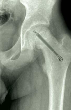
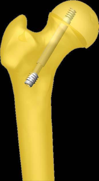
2 The Free-Gliding SCFE Screw System, designed to treat the most common hip problem in growing children, SLIPPED CAPITAL FEMORAL EPIPHYSIS (SCFE), continues the tradition of Pega Medical s family of innovative pediatric devices. This screw is intended to prevent or stop further slippage of the capito-femoral physis, in children with open growth plates. Medial and lateral threaded fixations, connected through a trilobe free-extending shaft provide stability. The Free-Gliding SCFE Screw System allows for physiological remodeling of the femoral head in order to maintain optimal neck/shaft ratio and biomechanical function. Surgical Planning and Implant Selection 2 The Free-Gliding SCFE Screw System Developed in collaboration with: François Fassier, MD Marie Gdalevitch, MD Shriners Hospitals for Children Montreal, Canada Surgical Technique 3 Retrieval 7 Driver Assembly 8 FG-ST-EN rev E
, a Female component (which anchors the femoral head) and a Cap.")

3 The Free-Gliding SCFE Screw is a free-extending cannulated screw designed specifically for the treatment of SCFE and neck fractures in skeletally immature patients. The implant assembly includes a Male component (which is attached to the lateral cortex), a Female component (which anchors the femoral head) and a Cap. The telescopic design will elongate with growth thus eliminating the need for a protruding screw position at the lateral cortex or pin advancement revision surgery. Moreover, the implant s design avoids compression of the growth plate while providing rotational stability. The device is inserted as simply as a standard threaded screw. Female component Male component Self-tapping / Self-drilling features Reverse cutting edges for easy removal Cap to avoid tissue ongrowth Surgical Planning The following described procedure is applicable to all intended uses of The Free-Gliding SCFE Screw System. The surgical technique should be performed under image intensification (C-arm) using a radiolucent or fracture table. DIAMETER CONSIDERATIONS Selection of the screw diameter is based on the femoral neck diameter. Available diameters are 6.5mm and 7.3mm. LENGTH CONSIDERATIONS The implant s placement should be 3mm short of the subchondral bone to avoid insertion into the joint. Direct measurement of the length of the screw assembly is done with the Depth Gage over the Guide Wire prior to reaming. To assure continued normal growth, the entire threaded portion of the female component must be past the growth plate and within the epiphysis in both the AP and Lateral views. Screw components are selected from Table 1. L - 3mm 2
4 Once the diameter is selected, Male and Female components are combined to obtain the desired final screw length. Table 1: Screw Selection Guide Ø 6.5 Ø 7.3 SCREW LENGTH MALE COMPONENT FEMALE COMPONENT SCREW LENGTH MALE COMPONENT FEMALE COMPONENT 48 SCF-M65-MS 50 SCF-M65-ML SCF-T65-48S/50L 48 SCF-M73-MS 50 SCF-M73-ML SCF-T73-48S/50L M I N I 52 SCF-M65-MS 54 SCF-M65-ML SCF-T65-52S/54L M I N I 52 SCF-M73-MS 54 SCF-M73-ML SCF-T73-52S/54L 56 SCF-M65-MS 58 SCF-M65-ML SCF-T65-56S/58L 56 SCF-M73-MS 58 SCF-M73-ML SCF-T73-56S/58L 60 SCF-M65-S 62 SCF-M65-L SCF-F65-60S/62L 60 SCF-M73-S 62 SCF-M73-L SCF-F73-60S/62L 64 SCF-M65-S 66 SCF-M65-L SCF-F65-64S/66L 64 SCF-M73-S 66 SCF-M73-L SCF-F73-64S/66L 68 SCF-M65-S 70 SCF-M65-L SCF-F65-68S/70L 68 SCF-M73-S 70 SCF-M73-L SCF-F73-68S/70L 72 SCF-M65-S 74 SCF-M65-L SCF-F65-72S/74L 72 SCF-M73-S 74 SCF-M73-L SCF-F73-72S/74L S TA N D A R D 76 SCF-M65-S 78 SCF-M65-L 80 SCF-M65-S 82 SCF-M65-L 84 SCF-M65-S 86 SCF-M65-L SCF-F65-76S/78L SCF-F65-80S/82L SCF-F65-84S/86L S TA N D A R D 76 SCF-M73-S 78 SCF-M73-L 80 SCF-M73-S 82 SCF-M73-L 84 SCF-M73-S 86 SCF-M73-L SCF-F73-76S/78L SCF-F73-80S/82L SCF-F73-84S/86L 88 SCF-M65-S 90 SCF-M65-L SCF-F65-88S/90L 88 SCF-M73-S 90 SCF-M73-L SCF-F73-88S/90L 92 SCF-M65-S 94 SCF-M65-L SCF-F65-92S/94L 92 SCF-M73-S 94 SCF-M73-L SCF-F73-92S/94L 96 SCF-M65-S 98 SCF-M65-L SCF-F65-96S/98L 96 SCF-M73-S 98 SCF-M73-L SCF-F73-96S/98L 100 SCF-M65-S 102 SCF-M65-L SCF-F65-100S/102L 100 SCF-M73-S 102 SCF-M73-L SCF-F73-100S/102L Assembled screw length can be validated using the Slide Ruler (SCF-SRL-100). Surgical Technique Step 1 ENTRY POINT The entry point must be at or above the level of the lesser trochanter. It should also be anterolateral, as opposed to the lateral entry point used in the fixation of fractures around the hip. Screws should be directed from anterolateral to posteromedial. Care should be taken to remain in the center of the capital epiphysis. Posterosuperior placement in the epiphysis should be avoided at all costs to prevent damage to the lateral epiphyseal vessels. 3


5 Step 2 INSERTION OF THE GUIDE WIRE Under image intensification, insert the Guide Wire through the Tissue Protector and the Guide Wire Sleeve into the epiphysis. The Guide Wire should end 3mm short of the subchondral bone. Validate the position of the Guide Wire under C-arm visualization in both AP and Lateral views prior to reaming. Guide Wire Sleeve Screw Size ø 6.5 ø 7.3 Guide Wire ø 2.0, SCF-GWR320 ø 2.4, SCF-GWR324 Tissue Protector Step 3 MEASUREMENT OF THE SCREW LENGTH Slide the tapered end of the Depth Gage into the Guide Wire Sleeve over the Guide Wire. Read the measurement at the end of the Guide Wire to obtain the screw length. For accurate measurement, the tip of the Guide Wire Sleeve should be in contact with the cortex. Remove the Guide Wire Sleeve and Depth Gage after measurement. Depth gage must rest against sleeve The end of the Guide Wire indicates the screw length For acurate measurement Pega Medical's Guide Wire (L = 330 mm) must be used. 72 If purchase in the cortex is a concern, subtract 2 mm from length measurement. 4
6 Step 4 REAMING Select the cannulated Reamer according to the diameter of the screw selected at Step 1. Reaming should be done under C-arm visualization to prevent advancement of the Guide Wire into the joint space. Do not force the Reamer when drilling becomes difficult. Partially retract the Reamer, when required, in order to clean out debris. Screw Size ø 6.5 ø 7.3 Reamer SCF-CAR065 SCF-CAR073 Insert the Reamer through the Tissue Protector and over the Guide Wire to avoid damaging the surrounding tissues. Advance the Reamer with steady and moderate pressure to begin reaming the screw canal. Ream up to but not through the growth plate. Do not ream the femoral capital epiphysis The threaded tip of the Guide Wire (distal 10mm) must remain unreamed to allow screw purchase and to maintain Guide Wire fixation. The screw is self-tapping and self-reaming in order to advance with ease into the epiphysis. Step 5 SCREW INSERTION 5.1 LOADING OF THE MALE COMPONENT Using the Driver (corresponding to the implant size), turn the locking knob until the Male component is fully engaged onto the Driver. There should be no space between the screw head and the Driver when properly assembled. If the Driver Handle, Thread Shaft and Knob are not assembled please refer to page 8 for Driver assembly instructions. 5

7 Male component Locking knob Driver must correspond to implant size Screw Size ø 6.5 ø 7.3 Driver SCF-MLD265 / SCF-MLD365 SCF-MLD273 / SCF-MLD373 Driver 5.2. LOADING OF THE FEMALE COMPONENT To complete the screw assembly, simply slide the Female component onto the Male component up to the collar of the Male component INSERTION OF THE ASSEMBLED SCREW The assembled screw is inserted into the reamed canal over the Guide Wire as would be a standard one-piece screw. This action simultaneously engages the thread of the Female into the epiphysis of the femoral head and the thread of the Male into the lateral cortex. Take care not to let the Male distract from the Female during insertion. Do not impact the Driver at insertion. Once the desired position of the screw is achieved, remove the Driver by unscrewing the locking knob (counterclockwise rotation). At this point, the range of motion must be checked (using the approach and withdrawal technique) under C-arm visualization to assure the screw does not exit the femoral head on any view. Contrast can be injected through the screw s cannulation to ensure no joint penetration. 6

8 Step 6 INSERTION OF THE CANNULATED CAP Using the cannulated Cap Driver insert the appropriate Cap into the Male component. Drive the Cap until it is fully engaged within the Male component. The Cap will prevent bone ongrowth and facilitate removal. The Guide Wire can now be removed. Screw Size ø 6.5 ø 7.3 Cap SCF-MC-065 SCF-MC-073 Caps are not interchangeable Do not overtighten since this may lead to inadvertent screw advancement. Cap Driver Retrieval of screw GUIDE WIRE INSERTION Under C-arm visualization, insert the Guide Wire through the implant s cannulation. The Guide Wire will facilitate guidance of the retrieval instruments. In the event of bone on-growth onto the Cap, a rongeur or reamer can be used to remove the excess bone CAP REMOVAL Use the Cap Driver to remove the Cap. MALE COMPONENT REMOVAL Engage the Driver into the Male component (as per step 5.1) by turning the locking knob clockwise. Remove the male component via a counterclockwise rotation of the handle. Note: It is normal for the Female component to rotate while the Male component is being removed. Driver 7


9 FEMALE COMPONENT REMOVAL Slide the Female Retriever over the Guide Wire and thread into the Female component using a counterclockwise rotation. Rotate while applying traction to remove the implant component. If insertion of the Female Retriever is difficult, reaming up to the female component might be required prior to removal. Screw Size Female Retriever Reamer ø 6.5 SCF-FER065 SCF-CAR065 ø 7.3 SCF-FER073 SCF-CAR073 Retriever must correspond to implant size Female Retriever Additional Recommendations Prophylactic pinning of the contralateral hip is recommended in many cases: noncompliant patients, endocrinopathy or renal disease, patients under 10 years of age or with open triradiate cartilage, children with syndromes, etc. The Modified Oxford Bone scoring system and posterior sloping angle may help identify the patients requiring prophylactic treatment. Driver Assembly For more details, please refer to document titled: ASSEMBLY/DISASSEMBLY INSTRUCTIONS FOR PROCESSING Thread Shaft Driver Handle Knob If required, use the Cap Driver to unlock the Knob with a counterclockwise rotation. Locked Position Unlocked Position HOLD Use the Cap Driver and T-handle to screw the Knob onto the Thread Shaft. 8
10 1111 Autoroute Chomedey, Laval, Quebec CANADA H7W 5J8 Phone: Fax: Pega Medical, Inc. Distributed by Pediatric Orthopedics at its Best US Patent Pending FG-ST-EN rev E
Ankle Fracture System. Surgical Technique STRENGTH FROM WITHIN
 Ankle Fracture System Surgical Technique STRENGTH FROM WITHIN Ankle Fracture System The Sonoma FibuLock nail is the first intramedullary device that has the same indications as plates and delivers anatomic
Zimmer Natural Nail System. Cephalomedullary Nail Surgical Technique SMALL
 Zimmer Natural Nail System Cephalomedullary Nail Surgical Technique SMALL Zimmer Natural Nail System Cephalomedullary Nail Technique - Small 1 Zimmer Natural Nail System Cephalomedullary Nail Surgical
Orthopedic Bone Nail System Universal Humeral Nail
 Orthopedic Bone Nail System Universal Humeral Nail Surgical Technique Manual Note: The surgical procedures should be performed under the guidance of qualified skilled orthopedic surgeons, and this surgical
Surgical Technique Guide
 Surgical Technique Guide Patented - www.flow-fx.net Flow-FX, LLC 9301 W 191st Street Mokena, IL 60448 P. 815.531.4424 by Flow-FX, LLC. 2017 Products referenced with TM are trademarks of Flow-Fx. STG-101
LCP Pilon Plate 2.7/3.5
 Surgical Technique LCP Locking Compression Plate Original Instruments and Implants of the Association for the Study of Internal Fixation AO/ASIF Table of contents Indications 3 Implants 4 Instruments 5
Surgical Technique. Customer Service:
 Patent Pending CAUTION: Federal Law (USA) restricts this device to sale by or on the order of a physician. Notes This page is blank INDICATIONS FOR USE The Extremity Medical Hallu X Intramedullary Fusion
Zimmer Natural Nail System
 Zimmer Natural Nail System Cephalomedullary Nail Surgical Technique Compact Case - Short Nails Only STANDARD Zimmer Natural Nail System Cephalomedullary Nail Surgical Technique - Standard 1 Zimmer Natural
Interlagos Retractor System Surgical Technique
 Interlagos Retractor System Surgical Technique TABLE OF CONTENTS Instructions for Use Design Rationale Surgical Technique 1. Pre-Operative Preparation 2. Pedicle Preparation 3. Primary Retraction 4. Secondary
Universal Humeral Nail
 990210009 INDEX Indications Preoperative Planning Patient Position Surgical Technique - Step 1 Open Humerus - Step 2 Calibrate The Nail - Step 3 Insert Nail - Step 4 Proximal Locking - Step 5 Assemble
Technique Guide Supplement. Standard DHS Lag Screw with LCP DHHS Sideplate.
 Technique Guide Supplement Standard DHS Lag Screw with LCP DHHS Sideplate. Table of Contents Surgical Technique Standard DHS Lag Screw with LCP DHHS 2 Sideplate Technique DHS One-step Lag Screw with DHHS
Zimmer Natural Nail System
 Zimmer Natural Nail System Cephalomedullary Nail Surgical Technique Compact Case- Short Nails Only SMALL Zimmer Natural Nail System Cephalomedullary Nail Technique - Small 1 Zimmer Natural Nail System
S U R G I C A L T E C H N I Q U E TRAUMA & EXTREMITIES GROUP
 S U R G I C A L T E C H N I Q U E TRAUMA & EXTREMITIES GROUP TABLE OF CONTENTS ATN NAIL SYSTEM DESIGN RATIONALE INDICATIONS/CONTRAINDICATIONS PREOPERATIVE PLANNING AND PATIENT POSITIONING NAIL INSERTION
The Percutaneous Reduction Forceps Technique Guide
 The Percutaneous Reduction Forceps Technique Guide Indications + Product Overview Introduction The Percutaneous Reduction Forceps The Percutaneous Reduction Forceps facilitate standard technique for fixation
6.5 mm and 7.3 mm Cannulated Screws Technique Guide
 6.5 mm and 7.3 mm Cannulated Screws Technique Guide An Integral Part of the SYNTHES Cannulated Screw System Original Instruments and Implants of the Association for the Study of Internal Fixation AO ASIF
The Titanium Cannulated Lateral Entry Femoral Recon Nail. Expert nailing system with radiolucent instrumentation.
 The Titanium Cannulated Lateral Entry Femoral Recon Nail. Expert nailing system with radiolucent instrumentation. Technique Guide EXPERT Nailing System Table of Contents Introduction Titanium Cannulated
Zimmer Natural Nail System
 Zimmer Natural Nail System Cephalomedullary Small Nail Surgical Technique Table of Contents Product Overview... 2 Implant Overview... 2 Indications... 3 Contraindications... 3 Surgical Technique... 4 Preoperative
Technique Guide. LCP Pilon Plate 2.7/3.5
 Technique Guide LCP Pilon Plate 2.7/3.5 LCP Pilon Plate 2.7/3.5 Table of contents Indications 3 Implants 4 Instruments 5 Surgical technique 6 Implant removal 12 Image intensifier control Warning This
The CentroNail System: Universal Femoral Nailing Applications
 O P E R A T I V E T E C H N I Q U E The CentroNail System: Universal Femoral Nailing Applications 1 2 3 FEATURES AND BENEFITS Proximal locking Locking screws 4 INDICATIONS 5 EQUIPMENT REQUIRED 9 17 26
Biomet Peritrochanteric Nail (PTN) System. Surgical Technique
 System. Surgical Technique") Biomet Peritrochanteric Nail (PTN) System Surgical Technique Contents Introduction... Page 1 Indications... Page 2 OTA Femoral Fracture Classifications... Page 3 Surgical Technique... Page 4 Patient Positioning...
Biomet Peritrochanteric Nail (PTN) System Surgical Technique Contents Introduction... Page 1 Indications... Page 2 OTA Femoral Fracture Classifications... Page 3 Surgical Technique... Page 4 Patient Positioning...
Gamma3 Trochanteric Nail 170 & 180. Operative technique
 Gamma3 Trochanteric Nail 170 & 180 Operative technique Gamma3 Trochanteric Nail 170 & 180 Contents 1. Design of the Gamma3 System....4 Gamma Nail 170 and 180... 4 Distal locking screws... 5 2. Indications
Technique Chart. DHS/DCS One-Step Insertion Wrench. For use with DHS/DCS One-Step Lag Screws.
 Technique Chart DHS/DCS One-Step Insertion Wrench. For use with DHS/DCS One-Step Lag Screws. DHS/DCS One-Step Insertion Wrench DHS Triple Reamer (338.13) Assembly 338.10 8.0 mm Drill Bit 338.11 DHS Reaming
Gamma3 Long Nail R1.5 and R2.0. Operative technique
 Gamma3 Long Nail R1.5 and R2.0 Gamma3 Long Nail R1.5 and R2 Gamma3 Long Nail R1.5 and R2.0 Contents 1. Design of the Gamma3 System...4 Lag screw and set screw function... 5 Distal locking screws... 5 2.
Introduction TRIGEN META-TAN Nail specifications Surgical technique Patient positioning Opening the proximal femur Intramedullary reaming
 Surgical Technique Table of contents Introduction... 2 TRIGEN META-TAN Nail specifications... 3 Surgical technique... 4 Patient positioning... 4 Opening the proximal femur... 5 Incision and entry point...
OR manual. PLATON ti) )))
 )))") OR manual PLATON ti) Characteristics of the PLATON ti system Variation I dynamic with sliding distance limitation Variation II AR Clip dynamic with sliding distance limitation PLATON ti-s PLATON ti-l Proximal
OR manual PLATON ti) Characteristics of the PLATON ti system Variation I dynamic with sliding distance limitation Variation II AR Clip dynamic with sliding distance limitation PLATON ti-s PLATON ti-l Proximal
TALON DISTALFIX Proximal Femoral Nail. Surgical Technique
 TALON DISTALFIX Proximal Femoral Nail Surgical Technique TALON DISTALFIX SLN-Nail Surgical Technique Table of Contents Introduction 3 TALON DISTALFIX SLN-Nail 3 Design Features 4 Indications/Contraindications
5th Metatarsal Fracture System Surgical Technique
 5th Metatarsal Fracture System Surgical Technique 5th Metatarsal Fracture System 5th Metatarsal Fracture System The 5th Metatarsal Fracture System (AR-8956S) is a uniquely designed screw and plate system
3.5 mm Cannulated Screw Technique Guide
 3.5 mm Cannulated Screw Technique Guide An Integral Part of the SYNTHES Cannulated Screw System Original Instruments and Implants of the Association for the Study of Internal Fixation AO ASIF The 3.5 mm
Features and Benefits 2. Indications and Pre-op Planning 7. Patient Positioning and Reduction 8. Entry and Canal Preparation 9.
 S U R G I C A L T EC H N I Q U E Contents Features and Benefits 2 Indications and Pre-op Planning 7 Patient Positioning and Reduction 8 Entry and Canal Preparation 9 Nail Insertion 12 Proximal Locking
Knee Nail for Retrograde Femoral Mode
 Surgical Technique *smith&nephewt TRIGEN IM Nail System Knee Nail for Retrograde Femoral Mode Table of Contents Indications 2 Surgical Technique 3 TRIGEN STABLE-LOK Nut & Washer Surgical Technique 16 TRIGEN
Anterior Cervical Plate SURGICAL TECHNIQUE GUIDE. Surgeon Driven Innovation
 Anterior Cervical Plate SURGICAL TECHNIQUE GUIDE Surgeon Driven Innovation 1 The Snowmass Anterior Cervical Plate System is intended for the surgical treatment and correction of traumatic and pathologic
OPERATIVE TECHNIQUE. The Centronail Titanium Universal Femoral Nailing System
 OPERATIVE TECHNIQUE The Centronail Titanium Universal Femoral Nailing System 1 2 3 FEATURES AND BENEFITS Proximal locking Locking screws 4 INDICATIONS 5 EQUIPMENT REQUIRED 9 17 26 28 ANTEGRADE INSERTION
Operasjonsteknikk. Retrograd Femur
 Operasjonsteknikk Retrograd Femur TRIGEN META-NAIL Retrograde Femoral Nail System Surgical Technique Table of Contents Indications...2 Implant Specifications...3 Surgical Technique Patient Positioning...4
Technique Guide. 7.0 mm Cannulated Screws. Part of the Synthes Cannulated Screw System.
 Technique Guide 7.0 mm Cannulated Screws. Part of the Synthes Cannulated Screw System. Table of Contents Introduction 7.0 mm Cannulated Screws 2 AO Principles 3 Indications 4 Surgical Technique Surgical
Integra. Capture Screw System SURGICAL TECHNIQUE
 Integra Capture Screw System SURGICAL TECHNIQUE Table of Contents Indications... 2 Contraindications... 2 System Description... 2 System Features... 2 Cannulated Low-Profile Screws (AC-Series) Overview...
Technique Guide. 4.5 mm Cannulated Screws. Part of the Synthes Cannulated Screw System.
 Technique Guide 4.5 mm Cannulated Screws. Part of the Synthes Cannulated Screw System. TableofContents Introduction 4.5 mm Cannulated Screws 2 AO Principles 3 Indications 4 Surgical Technique Surgical
LCP Pilon Plate 2.7/3.5
 LCP Pilon Plate 2.7/3.5 Surgical Technique This publication is not intended for distribution in the USA. Instruments and implants approved by the AO Foundation. Table of contents Indications 2 Implants
OPERATIVE TECHNIQUE RIVAL VIEW PLATING SYSTEM. foot & ankle reconstruction procedures
 OPERATIVE TECHNIQUE RIVAL VIEW PLATING SYSTEM foot & ankle reconstruction procedures INTRODUCTION 3 SYSTEM DESCRIPTION 3 TECHNICAL DETAILS 4 SALES AND MARKETING CONFIGURATION 5 OPERATIVE TECHNIQUE 7 OPERATIVE
Integra. Stainless Headed Compression Screw System SURGICAL TECHNIQUE
 Integra Stainless Headed Compression Screw System SURGICAL TECHNIQUE Table of Contents Design Rationale...2 Indications...2 Contraindications...2 Surgical Technique Step 1: Inserting Guide Wire... 3 Step
Technique Guide. LCP Dynamic Helical Hip System (DHHS). Part of the Synthes Large Fragment LCP System.
. Part of the Synthes Large Fragment LCP System.") Technique Guide LCP Dynamic Helical Hip System (DHHS). Part of the Synthes Large Fragment LCP System. Table of Contents Introduction LCP Dynamic Helical Hip System (DHHS) 2 AO Principles 4 Indications
Technique Guide LCP Dynamic Helical Hip System (DHHS). Part of the Synthes Large Fragment LCP System. Table of Contents Introduction LCP Dynamic Helical Hip System (DHHS) 2 AO Principles 4 Indications
SURGICAL TECHNIQUE GUIDE
 SURGICAL TECHNIQUE GUIDE DANGER indicates an imminently hazardous situation which, if not avoided, will result in death or serious injury. WARNING indicates a potentially hazardous situation which, if
Carpal Tunnel Ligament Release
 Hip Gamma3 KnifeLight Trochanteric Nail 180 Carpal Tunnel Ligament Release Operative Technique Operative Technique Hip Fractures Trochanteric Nail 180 Contributing Surgeons Prof. Kwok Sui Leung, M. D.
Humeral Nail System Procedural Steps.
 Humeral Nail System Procedural Steps www.carbo-fix.com Table of Contents Introduction..3 Instrumentation Set... 8 Procedural Steps: Humeral Nail.........10 Procedural Steps: Proximal Humeral Nail.....13
Proximal Femur Nailing System Surgical Technique. fix.com
 ProximalFemurNailingSystem SurgicalTechnique www.carbofix.com Implants Introduction The Nail and Lag Screw are made of longitudinal continuous carbon fiber reinforced polymer (PEEK). The screws are made
Table of Contents 2-6. Introduction. Indications Surgical Technique. Ordering Information 15-24
 Table of Contents Introduction Product information ExtremiFix Midsize Large Screw Offering Headless Screw Characteristics Design Features & Benefits Instrumentation Technical Details Calibrated Drill Bits
MaxTorque. surgical technique. Cannulated Screw System. Foot & Ankle. OrthoHelix Technology
 MaxTorque Cannulated Screw System OrthoHelix Technology surgical technique Foot & Ankle 2 M A X T O R Q U E C A N N U L A T E D S C R E W S Y S T E M Table of Contents Advantages 3 Indications 4 Contraindications
SpeedTip CCS 5.0, 7.0
 SURGICAL TECHNIQUE STEP BY STEP SpeedTip CCS 5.0, 7.0 Cannulated Compression Screws APTUS 2 SpeedTip CCS 5.0, 7.0 Cannulated Compression Screws SpeedTip CCS 5.0, 7.0 Cannulated Compression Screw 3 SpeedTip
DART-FIRE. Small Screw System SURGICAL TECHNIQUE
 DART-FIRE Small Screw System SURGICAL TECHNIQUE DART-FIRE Small Screw System SURGICAL TECHNIQUE Contents Chapter 1 4 Chapter 2 6 Appendix 1 9 Appendix 2 11 Introduction DART-FIRE Small Screw System Surgical
OPERATIVE TECHNIQUE RIVAL BITE HEADED CANNULATED AND HEADLESS COMPRESSION SCREWS. foot & ankle applications
 OPERATIVE TECHNIQUE RIVAL BITE HEADED CANNULATED AND HEADLESS COMPRESSION SCREWS foot & ankle applications INTRODUCTION 3 SYSTEM DESCRIPTION 3 TECHNICAL DETAILS 4 SALES AND MARKETING CONFIGURATION 6 OPERATIVE
DART-FIRE. Small Screw System SURGICAL TECHNIQUE
 DART-FIRE Small Screw System SURGICAL TECHNIQUE DART-FIRE Small Screw System Surgical Technique Contents Chapter 1 4 Chapter 2 6 Chapter 3 7 Appendix 1 10 Appendix 2 12 Introduction Intended Use DART-FIRE
MTP Set SURGICAL TECHNIQUE
 MINI MAXLOCK EXTREME MTP Set SURGICAL TECHNIQUE Contents Table of Contents Key Design Features 3 Surgical Technique Standard MTP Plate 4 MTP Plate with POCKETLOCK Technology 10 Implants and Instruments
Pocket Reference Cards
 Stryker Nailing T2 Pocket Reference Cards Tibial Nails Femoral Nails Humeral Nails T2 Arthrodesis Nails Flexible Nails General Notes The following notes apply to all T2 IM Nails (except T2 Kids) unless
HipHip Fracures. Gamma3. Trochanteric Nail 180
 HipHip Fracures Gamma3 Trochanteric Nail 180 Gamma3 Trochanteric Nail 180 Contributing Surgeons Prof. Kwok Sui Leung, M. D. Chairman of Department of Orthopaedics and Traumatology The Chinese University
Fibula Plating System
 ANATOMIC LOCKED PLATING SYSTEM Fibula Plating System Securing optimal fixation through versatile locked and compression plating technology Contents Surgeon Design Team 2 Introduction 3 Anatomic Fibula
CHARLOTTE. Multi-Use Compression Screw
 CHARLOTTE Multi-Use Compression Screw CHARLOTTE multi-use compression screw surgical technique SURGICAL ADVISORS ROBERT ANDERSON, MD BRUCE COHEN, MD W. HODGES DAVIS, MD Proper surgical procedures and techniques
Technique Guide. Variable Angle LCP 1 st MTP Fusion Plates 2.4/2.7. Part of the Variable Angle LCP Forefoot / Midfoot System 2.4 / 2.7.
 Technique Guide Variable Angle LCP 1 st MTP Fusion Plates 2.4/2.7. Part of the Variable Angle LCP Forefoot / Midfoot System 2.4 / 2.7. Table of Contents Introduction Variable Angle LCP 1 st MTP Fusion
surgical technique addendum
 s h o u l d e r Solutions by Tornier Aequalis reversed II shoulder system surgical technique addendum Aequalis reversed II threaded post baseplate surgical technique addendum s u r g i c a l t e c h n
HCS 2.4/3.0. The countersinkable compression screw.
 Technique Guide HCS 2.4/3.0. The countersinkable compression screw. Table of Contents Introduction Features and Benefits 2 Functional Principle 3 Indications 4 Surgical Technique Hand Scaphoid 5 Foot
ORTHOLINK. 2 - Hole Wedge Osteotomy Plate SURGICAL TECHNIQUE
 MAXLOCK EXTREME ORTHOLINK 2 - Hole Wedge Osteotomy Plate SURGICAL TECHNIQUE Contents Key Design Features 3 Surgical Technique 4 Implants and Instruments 7 Proper surgical procedures and techniques are
Surgical Technique International Version
 Surgical Technique International Version TRIGEN INTERTAN Intertrochanteric Antegrade Nail Surgical Technique As described by: Professor Dr. med. J.M. Rueger Thomas A. Russell, MD Roy W. Sanders, MD Paul
7.0 mm Cannulated Screws
 Part of the DePuy Synthes Cannulated Screw System 7.0 mm Cannulated Screws Surgical Technique Table of Contents Introduction 7.0 mm Cannulated Screws 2 AO Principles 3 Indications 4 Surgical Technique
DISTAL RADIUS PLATES 3.5 mm / ANGULARLY STABLE. Distal radius plates 3,5 mm / angularly stable. Locking bone screws. Cortical bone screw
 SURGICAL NÁSTROJE TECHNIQUE PRO ARTROSKOPII DISTAL INSTRUMENTS RADIUS PLATES FOR ARTHROSCOPY 3.5 mm / ANGULARLY STABLE Distal radius plates 3.5 mm / angularly stable Indication The plates are used for
DART-FIRE. Small Screw System SURGIC A L T ECHNIQUE
 DART-FIRE Small Screw System SURGIC A L T ECHNIQUE Contents Headline Headline PREFACE Chapter 1 4 Chapter 2 6 Chapter 3 7 Appendix A 10 Appendix B 12 Introduction Intended Use DART-FIRE Small Screw System
Omega 3 System Compression Hip Screw
 Omega 3 System Compression Hip Screw Hip Fracture Axially Stable Locking Option Contents Omega3 Compression Hip Screw Introduction 4 Potential Features & Benefits 5 Relative Indications & Contraindications
MEDICAL ADVANCED TECHNOLOGY EMERGENCY REMOVAL UNIVERSAL EXTRACTION SET. for Intramedullary Nail System
 MEDICAL ADVANCED TECHNOLOGY EMERGENCY REMOVAL UNIVERSAL EXTRACTION SET for Intramedullary Nail System introducing ourselve Manufacturer of surgical implants and medical devices. Solutions for patient orthopaedic
4.0 CANNULATED SCREW SYSTEM
 Surgical Technique 4.0 CANNULATED SCREW SYSTEM Surgical technique Table of contents Design features...2 Indications...3 Surgical technique...4 Inserting the screw...4 Extracting the screw...6 Catalog
Carpal Tunnel Ligament Release
 Hip T2 KnifeLight Recon Nailing System R2.0 Carpal Tunnel Ligament Release Femur Operative Technique Operative Technique Hip & Femur Fractures T2 Recon Nailing System Contributing Surgeons We greatly acknowledge
The Universal Nail System TECHNIQUE GUIDE
 The Universal Nail System TECHNIQUE GUIDE R Original Instruments and Implants of the Association for the Study of Internal Fixation AO ASIF Table of Contents.. THE..... UNIVERSAL............ NAILS............................
T2 Recon Nailing System
 Osteosynthesis T2 Recon Nailing System Operative Technique Contributing Surgeons: Kyle F. Dickson, MD, MBA Professor and Chairman University of Texas Medical School at Houston Department of Orthopaedic
SpeedTip CCS 5.0, 7.0
 SURGICAL TECHNIQUE STEP BY STEP SpeedTip CCS 5.0, 7.0 Cannulated Compression Screws APTUS 2 SpeedTip CCS 5.0, 7.0 Cannulated Compression Screws Contents 3 Introduction Product Materials Indications Contraindications
Expert HAN. Expert Hindfoot Arthrodesis Nail.
 Expert HAN. Expert Hindfoot Arthrodesis Nail. Technique Guide Expert Nailing System Table of Contents Introduction Expert Hindfoot Arthrodesis Nail 2 AO Principles 4 Indications 5 Surgical Technique Preoperative
1.5 MM LCP SYSTEM. For treatment of fractures and arthrodeses of canines and felines SURGICAL TECHNIQUE
 1.5 MM LCP SYSTEM For treatment of fractures and arthrodeses of canines and felines SURGICAL TECHNIQUE TABLE OF CONTENTS INTRODUCTION 1.5 mm LCP System 2 AO Principles 4 SURGICAL TECHNIQUE Reduce Fracture
Treace Medical Concepts Plating System
 Treace Medical Concepts Plating System Multiplanar Fixation System Surgical Technique Lapidus and 1 st MTP Fusion Lapidus Fusion Surgical Approach 1. Perform a longitudinal incision dorsally over the 1
VECTRA SURGICAL TECHNIQUE. Anterior cervical plate system. This publication is not intended for distribution in the USA.
 VECTRA Anterior cervical plate system This publication is not intended for distribution in the USA. SURGICAL TECHNIQUE Image intensifier control This description alone does not provide sufficient background
Operative Technique Hip Fracture Systems
 Gamma3 Trochanteric Nail 180 Operative Technique Hip Fracture Systems Trochanteric Nail 180 Contributing Surgeons: Prof. Kwok Sui Leung, M. D. Chairman of Department of Orthopaedics and Traumatology The
Global Cup System. Surgical Technique
 Global Cup System Surgical Technique Contents Introduction 2 Pre-operative Planning 3 Suggested Templating Method 3 Surgical Technique 4 Surgical Exposure 4 Acetabular Reaming 4 Acetabular Cup Trialling
PRE-OPERATIVE PREPARATIONS
 SURGICAL TECHNIQUE PRE-OPERATIVE PREPARATIONS Pre-operative X-ray will help to determine the diameter of the nail to be used. Using X-ray of uninjured femur may also help in determining diameter and length
Technique Guide. 2.4/2.7 mm Locking Tarsal Plates. Talus Plate, Navicular Plate and Cuboid Plate.
 Technique Guide 2.4/2.7 mm Locking Tarsal Plates. Talus Plate, Navicular Plate and Cuboid Plate. Table of Contents Introduction 2.4/2.7 mm Locking Tarsal Plates 2 AO Principles 4 Indications 5 Clinical
TwinFix Surgical Protocol. 3.2mm Cannulated Compression Screw System
 TwinFix Surgical Protocol Compression Screw System TwinFix Compression Screw System Indications for Use: The Stryker TwinFix Interfragmentary Compression Screw System is intended to be used for fractures
Operative Technique Hip Fracture Systems
 Gaa3 Long Nail R2.0 Operative Technique Hip Fracture Systems Gaa3 Long Nail R2.0 Contributing Surgeons: Prof. Kwok Sui Leung, M. D. Chairman of Department of Orthopaedics and Traumatology The Chinese University
76 Inventor: steps: Lurline Dr., Foster Primary Examiner-Guy V. Tucker
 I USOO56O1550A United States Patent (19) 11) Patent Number: Esser (45) Date of Patent: Feb. 11, 1997 54). PELVIC PIN GUIDE SYSTEM FOR 681829 10/1939 Germany... 606/96. INSERTION OF PINS INTO LIAC BONE
MTP Fusion Surgical Technique
 MTP Fusion Surgical Technique Patent and Patent Pending CAUTION: Federal Law (USA) restricts this device to sale by or on the order of a physician. INDICATIONS FOR USE The Omni Foot Plating System is intended
EX NAIL INSTRUMENTATION
 EX NAIL INSTRUMENTATION PRODUCT OVERVIEW OPENING INSTRUMENTS Awl Description Cannulated to accommodate a 3.0 mm Ball Tipped Reaming Rod 03.037.008 8.0 mm Cannulated Curved Awl Wire Guide Accessory Removable
OPERATIVE TECHNIQUE RIVAL REDUCE FRACTURE PLATING SYSTEM. foot & ankle trauma procedures
 OPERATIVE TECHNIQUE RIVAL REDUCE FRACTURE PLATING SYSTEM foot & ankle trauma procedures INTRODUCTION 3 SYSTEM DESCRIPTION 3 TECHNICAL DETAILS 4 SALES AND MARKETING CONFIGURATION 5 OPERATIVE TECHNIQUE 7
Gamma3 Trochanteric Nail 170
 Gamma3 Trochanteric Nail 170 Operative Technique Hip Fracture Trochanteric Nail 170 Contributing Surgeons: Prof. Kwok Sui Leung, M. D. Chairman of Department of Orthopaedics and Traumatology The Chinese
Instructions for Use. LCP Locking Compression Plate. Combine without Compromise.
 Instructions for Use LCP Locking Compression Plate. Combine without Compromise. Table of Contents LCP: Combine without Compromise 2 AO ASIF Principles of Osteosynthesis 4 Indications and Contraindications
Technique Guide. Synapse System. An enhanced set of instruments and implants for posterior stabilization of the cervical and upper thoracic spine.
 Technique Guide Synapse System. An enhanced set of instruments and implants for posterior stabilization of the cervical and upper thoracic spine. Table of Contents Introduction Synapse System 2 AO Principles
ISO Plate SURGICAL TECHNIQUE
 MINI MAXLOCK EXTREME ISO Plate SURGICAL TECHNIQUE Contents Table of Contents Key Design Features 2 Surgical Technique 3 Implants and Instruments 8 Key Design Features The MINI MAXLOCK EXTREME ISO (Intraosseous
Mecron Cannulated Screws
 Surgical Technique and Ordering Information 2 Table of contents Description... 4 Indications for use... 4 Contraindications... 4 State-of-the-art design features... 5 Surgical Technique... 6 Surgery Steps
Technique Guide. Variable Angle LCP Opening Wedge Plates 2.4/2.7. Part of the Variable Angle LCP Forefoot / Midfoot System 2.4 / 2.7.
 Technique Guide Variable Angle LCP Opening Wedge Plates 2.4/2.7. Part of the Variable Angle LCP Forefoot / Midfoot System 2.4 / 2.7. Table of Contents Introduction Variable Angle LCP Opening Wedge Plates
Technique Guide MTP Arthrodesis System
 Technique Guide MTP Arthrodesis System The CheckMATE MTP Arthrodesis System features low-profile, anatomically pre-contoured Bone Plates with either a combination of locking and non-locking holes or all-locking
Part of the DePuy Synthes Cannulated Screw System. 3.5 mm Cannulated Screws
 Part of the DePuy Synthes Cannulated Screw System 3.5 mm Cannulated Screws Surgical Technique Table of Contents Introduction 3.5 mm Cannulated Screws 2 AO Principles 3 Indications 4 Surgical Technique
Distal Fibula Plate SURGICAL TECHNIQUE
 MAXLOCK EXTREME Distal Fibula Plate SURGICAL TECHNIQUE Contents Key Design Features 3 Surgical Technique 4 Implants and Instruments 8 Proper surgical procedures and techniques are the responsibility of
VECTRA. SURGICAL TECHNIQUE. Anterior cervical plate system. This publication is not intended for distribution in the USA.
 VECTRA. Anterior cervical plate system. This publication is not intended for distribution in the USA. SURGICAL TECHNIQUE Contents Indications and contraindications Implants Vario Case Instruments Surgical
Distal Medial Tibia Plate Surgical Technique
 Locking Compression Technology by aap 1 Disclaimer This surgical technique is exclusively intended for medical professionals, especially physicians, and therefore may not be regarded as a source of information
Ulna Shortening System 2.5
 SURGICAL TECHNIQUE STEP BY STEP Ulna Shortening System 2.5 APTUS Wrist 2 Ulna Shortening System 2.5 Contents 3 Introduction Product Materials Indications Contraindications Color Coding 4 General Instrument
Aesculap Orthopaedics Targon RF. Retrograde Femoral Nail
 Aesculap Orthopaedics Targon RF Retrograde Femoral Nail Retrograde Femoral Nail The implantation of interlocking nails from an antegrade access has become the gold standard for most fractures of the femoral
Synapse System. An enhanced set of instruments and implants for posterior stabilization of the upper spine.
 Synapse System. An enhanced set of instruments and implants for posterior stabilization of the upper spine. Technique Guide 100º Instruments and implants approved by the AO Foundation Table of Contents
MEDIALMAX System SURGICAL TECHNIQUE
 MAXLOCK EXTREME MEDIALMAX System SURGICAL TECHNIQUE Contents The MEDIALMAX Advantage Design Feature Various flex options POCKETLOCK Technology Anatomic design Advantage Provides the surgeon with multiple
Optima ZS Spinal Fixation System
 Surgical Technique Optima ZS Spinal Fixation System The low-profile, in-line, polyaxial pedicle screw system. Optima ZS Surgical Technique 1 Optima ZS Spinal Fixation System The Optima ZS Spinal Fixation
Aviator Anterior Cervical Plating System System Overview. Visual and tactile confirmation Increased Angulation Simplified instrumentation
 Aviator Anterior Cervical Plating System System Overview Visual and tactile confirmation Increased Angulation Simplified instrumentation The Aviator anterior cervical plating system offers a unique double