REVIEW ENTIRE INSTALLATION GUIDE. This step gives you the opportunity to contact your dealer to answer any questions before you begin.
|
|
|
- William Tyler
- 6 years ago
- Views:
Transcription
1 Cabriolet Shelter (Retractable Roof) Step by Step Assembly Instructions Before You Begin These installation instructions will lead you through the process of installing your new shelter. The installation of the shelter requires special attention to certain detail. Before you begin you should: CHECK YOUR ORDER. Make sure the contents of the carton match the product numbers on your order. Contact your dealer if there are any damaged, missing or incorrect parts. PAY ATTENTION TO SAFETY. Because of the size and weight of certain parts, installation is recommended with no fewer than two people. Always maintain a clean, organized work area. MAKE SURE YOU HAVE THE RIGHT TOOLS AND MATERIALS. Jardin de Ville supplies the appropriate fasteners upon request through your dealer for anchoring the shelter securely to the ground. If you are unsure about the required anchoring system best suited for your shelter, consult your dealer for the proper fastening method. REVIEW ENTIRE INSTALLATION GUIDE. This step gives you the opportunity to contact your dealer to answer any questions before you begin. Assembly Requirements Two Persons Hand Drill Ladder Wrench Kit Tape Measure Level Rubber Hammer Screwdriver Set 1 of 15

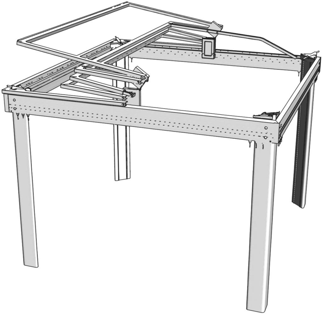
2 Assembly Overview 2 of 15
 Triangular Corner Post")


 Roof Hinge (right) 4x PL102 Plastic")

3 Part List 2x B1 10 Side Beam (roof hinge side) 2x B2 4x P1 4x P2 12 or 14 Front Beam (transverse side) Triangular Corner Post Corner Post Cover 1x L1 Full Length Lever Arm 1x L2 Dummy Lever Arm 2xTF1 Transverse Roof Support with groove Cross-Sectional View 3xTF2 Transverse Roof Support (no groove) Cross-Sectional View 4xTS1 Lower Truss with 5/16 dia hole about pivot point 4xTS2 Middle Truss with 5/16 dia hole about pivot point 2xTS3 Center Truss with plastic spring slide and corner inserts TS1 TS2 TS3 TS2 2x R1 Flat Bar Roof Trusses TS1 1x R2 Lever Arm Strap KC01 1x KC02 4x LA3002 Post End Plate 16x 002 Plate Screw 1/4 x 1-3/4 1x KC.02L 1x KC.02R KC04 Roof Hinge (left) Roof Hinge (right) 4x PL102 Plastic Corner Beam Inserts 2x KC03 8x 025 8x 013 Metal Screw #8-3/4 Metal Screw #8-1 1x PL005 Roof Hinge Cover KC05 Inlcudes the following sub kits: 8x PL007 Plastic Corner Insert 1x SKC03-1 1x SKC03-2 1x SKC of 15


4 Part List 2x SKC03-1 KC06 2x 001 Tab Washer 1/ x 003 Carriage Bolt - 5/16 x 2 2x 005 9/32 x 5/8 Flat Washer 16x 007 5/16 x 1-1/2 Flat Washer 2x 008 5/16 x 1/2 Lock Washer 16x 012 5/16 Nylon Lock Nut 2x 014 2x 026 Hex Bolt - 1/4-20 x 5/8 Roof Hinge Cover Screw #10-3/8 KC07 4x PL07 4x PL015 2x SKC03-2 4x PL016 4x PL014 2x 003 Carriage Bolt - 5/16 x 2 16x 002 Cover Screw - 1/4 x 1-3/4 4x 006 5/16 x 3/4 Flat Washer KC08 2x 009 5/16 x 5/8 Lock Washer 1x 002 Strap Screw - 1/4 x 1-3/4 2x 011 5/16 Nut 2x 018 1/4 dia Nylon Bushing 2x 019 Nylon Bushing - 5/16 1x 005 9/32 x 5/8 Flat Washer 1x 010 Nylon Lock Nut - 1/4-20 2x SKC03-3 2x PL011 Lever Arm Fork 5x x 006 5x 012 5/16 x 3/4 Flat Washer 5/16 Nylon Lock Nut Hex Bolt - 5/16 x 3-1/4 1x PL012 2x 016 Fork Installation Guide Self-Tapping Screw - #12 x 1-3/4 10x 019 Nylon Bushing - 5/16 2x PL010 2x 020 Hinge Box Side Cover 1x PL013 Plastic Finishing Hole Cap Lever End Cover 1x KC18 2x ATT01 2x 053 Flat Head Tek Screw 3/4" Rubber Strap MISC K.PL101 Pulleys included with curtains 4x ATT04 Plastic Locking Hook 20x K.APL001 Velcro Strips #8 Square Head Screwdriver Bit 8x 040 Self-Taping Screws #8-1/2" #10 Square Head Screwdriver Bit 4 of 15
![Getting Started 1 Post end with holes P1 Secure the base plates [ KC01.LA3002] to the bottom of each of the aluminum corner posts [P1] using metal bolts [KC01.](/docs-images/74/71271321/images/5-1.jpg "002] as shown in the diagram. (Repeat step for all four corner posts.) LA3002 002 2 KC.")
![02L 001 005 B1 008 014 Install the two roof hinges on the beams [B1] by first inserting two tab nuts [001] into the bottom interior groove of both beams.](/docs-images/74/71271321/images/5-2.jpg "Then slide the tab nuts till the mid section of the beams.")
![Install the roof hinges on both beams using tab nuts, bolts and washers from kit [SKC03-1] shown in the above right hand side diagram. LIGHTLY TIGHTEN BOLTS.](/docs-images/74/71271321/images/5-4.jpg "The hinge will be centered and bolts will be tighten in step 6. 3 On a flat surface, assemble all the beams together by inserting the plastic corners [KC04.PL102] at each end.")
5 Getting Started 1 Post end with holes P1 Secure the base plates [ KC01.LA3002] to the bottom of each of the aluminum corner posts [P1] using metal bolts [KC01.002] as shown in the diagram. (Repeat step for all four corner posts.) LA KC.02L B Install the two roof hinges on the beams [B1] by first inserting two tab nuts [001] into the bottom interior groove of both beams. Then slide the tab nuts till the mid section of the beams. Install the roof hinges on both beams using tab nuts, bolts and washers from kit [SKC03-1] shown in the above right hand side diagram. LIGHTLY TIGHTEN BOLTS. The hinge will be centered and bolts will be tighten in step 6. 3 On a flat surface, assemble all the beams together by inserting the plastic corners [KC04.PL102] at each end. Once fully inserted, lock in place the plastic corners with supplied screws [KC04.025], as shown in view A-A. You may use pieces of the cardboard shipping box to protect the frame from scratches. View A-A B2 B1 025 PL102 B2 Hole used in step 15 Cardboard B1 A-A Roof will open from this side 5 of 15

![A-A View A-A Use a Rubber Hammer Middle Truss Assembly Complete the assembly by inserting the trusses [TS1], [TS2] and [TS3] at each end of the transverse roof supports](/docs-images/74/71271321/images/6-1.jpg "as shown in the figure above. Again you will need a rubber hammer to insert them properly.")
6 Assembling the Roof 4 Use a Rubber Hammer TF1 & TF2 PL007 Install the plastic corner inserts [KC05.PL007] at each end of the transverse roof supports [TF1] & [TF2] as shown in the figure above. You will need a rubber hammer to insert them properly. A-A View A-A Use a Rubber Hammer Middle Truss Assembly Complete the assembly by inserting the trusses [TS1], [TS2] and [TS3] at each end of the transverse roof supports as shown in the figure above. Again you will need a rubber hammer to insert them properly. 5 TS1 & TS2 Roof Truss Ends 019 Nylon Bushing On each end of the roof truss assemblies [TS1] & [TS2] install two plastic bushing [SKC ] as shown in the diagram. 6 of 15

7 Assembling the Roof Framework 6 TS1 TS2 TS3 TS2 TS1 B-B D-D C-C E-E Lay the trusses on top of the beam assembly in the order and orientation shown by the diagram above. Consult views B-B, C-C, D-D and E-E for specific detail. Then turn to the next page for a description on how to fix each trusses to the hinges. Install the middle plastic stub truss on the lower hole. The upper hole can be used in time if more pressure needs to be exerted by the middle truss onto the roof fabric. View B-B Holes used for Lever Arm and dummy Lever Arm (see Step 9) View C-C Holes used for Lever Arm and dummy Lever Arm (see Step 9) TF1 View D-D View E-E TF1 Transverse Support Groove Should be Facing Downwards 7 of 15


 006 Center Hinge Assembly F-F F-F Once the")

![beyond the edge of beam [B2] (see view F-F).](/docs-images/74/71271321/images/8-4.jpg "Then tighten the hinge bolts as shown in the bottom right diagram.")
8 Assembling the Roof Framework Install the trusses on the hinge using hardware from kit [SKC03-2] shown in views B-B. Notice that only one side is shown. Repeat this step on the other hinge. Nylon bushing 019 KC.02L See Through View 012 View B-B (Hardware Installation) View B-B (TOP VIEW) 006 Center Hinge Assembly F-F F-F Once the trusses have been fixed properly to each hinge, center the roof assembly by allowing the protruding groove of [TF1] to extend just beyond the edge of beam [B2] (see view F-F). Then tighten the hinge bolts as shown in the bottom right diagram. Transverse Support Groove Facing Downwards View F-F 014 Tighten Bolts (repeat on other side) 8 of 15
 Attach one of the four corner posts [P1] to each corner of the structure using")
![hardware from kit [KC06] shown in the top right diagrams.](/docs-images/74/71271321/images/9-2.jpg "This step may require a second person or a ladder to lift the roof assembly in order")
![to fix all four corner posts [P1]. See diagrams below for further assembly steps.](/docs-images/74/71271321/images/9-3.jpg "P1 P1 P2 To complete the post assembly, snap together the corner posts [P1] and")
![corner post covers [P2] using a rubber hammer as shown in the diagrams above.](/docs-images/74/71271321/images/9-4.jpg "Repeat step for each corner.")

9 Installing the Corner Posts 7 G-G Flat Washer 012 Lock-Nut View G-G (TOP VIEW) Attach one of the four corner posts [P1] to each corner of the structure using hardware from kit [KC06] shown in the top right diagrams. This step may require a second person or a ladder to lift the roof assembly in order to fix all four corner posts [P1]. See diagrams below for further assembly steps. P1 P1 P2 To complete the post assembly, snap together the corner posts [P1] and corner post covers [P2] using a rubber hammer as shown in the diagrams above. Repeat step for each corner. 002 KC07 Assembly Locking Key P2 Top View P2 Then fasten the top cover assembly [KC07] on top of each corner post [P1]. DO NOT OVER TIGHTEN SCREWS. The locking key can be in the unlocked position or removed from the cover assembly by turning then pulling it. 9 of 15


![measurements Dimensions given from center to center of plates [LA3002] Structure Anchorage System Recommendations](/docs-images/74/71271321/images/10-5.jpg "OPTION A WOOD DECK/FLOOR OPTION B CONCRETE/CEMENT FLOOR Requirements: 8 (2 per plates) of each - 5/16\" x 2\" wood screws")

10 Archoring the Shelter 8 Make sure the structure is well aligned and levelled with the floor as shown in the diagram below. Consult the section below for recommendations on the type of anchorage required for fixing the structure on the floor. L W D C2 C3 level C1 Remaining holes in plate [LA3002] are used for fixing the structure on the floor See ANNEX 1 for measurements Dimensions given from center to center of plates [LA3002] Structure Anchorage System Recommendations OPTION A WOOD DECK/FLOOR OPTION B CONCRETE/CEMENT FLOOR Requirements: 8 (2 per plates) of each - 5/16" x 2" wood screws - 5/16" washers Requirements: 8 (2 per plates) of each - 3/8" x 1-1/2" expansion anchor * use 1/2" cement drill bit CONCRETE WOOD SOIL PAVER/GRASS This anchoring system is the recommended solution for anchoring your tent on other surfaces than wood or concrete such as paver or grass. Consult your dealer for more information on this fastening method. 10 of 15
 016 View H-H (step b) Install the plastic fork [KC08.")
![PL011] on the [TS2] truss assembly on the opening side.](/docs-images/74/71271321/images/11-1.jpg "Locate the proper position of the fork by using the fork installation guide [KC08.")
![PL012] as shown in views H-H. Then use the self tapping screw [KC08.](/docs-images/74/71271321/images/11-3.jpg "016] to fix the fork on the transverse truss member.")

 PL005 L1 View I-I (TOP VIEW) L1 L1 To complete the roof hinge mechanism,")
11 Final Frame Assembly 9 I-I H-H PL012 TS2 PL011 Remove the guide after installing the fork. View H-H (step a) 016 View H-H (step b) Install the plastic fork [KC08.PL011] on the [TS2] truss assembly on the opening side. Locate the proper position of the fork by using the fork installation guide [KC08.PL012] as shown in views H-H. Then use the self tapping screw [KC08.016] to fix the fork on the transverse truss member. Then insert the end of the lever arm on the fork and fix the lever using hardware from kit [SKC03-2] shown in view I-I. Repeat step on other side for the dummy lever arm See Through View 003 PL011 KC.02L 10 View H-H (step c) PL005 L1 View I-I (TOP VIEW) L1 L1 To complete the roof hinge mechanism, install the plastic hinge cover [KC03.PL005] over the roof hinge using screws [SKC ]. Then install side cover [KC08.PL010] and the hole cap [KC08.020]. Repeat step on both side. PL Install the Plastic Finishing Cap 11 of 15
![Final Frame Assembly 11 018 010 005 Install the lever strap on the end of the lever arm using hardware from kit [KC08] shown in the left diagram.](/docs-images/74/71271321/images/12-0.jpg "Then install the plastic cap [PL013] on the end of both the lever and PL013 R2 002 12 Roof Support TS1 053 B2 Center Line 5-1/2 ATT04 Locate the")
![center distance of beam [B2].Then install the rubber strap [KC18.ATT01] using the Tek screw [KC18.](/docs-images/74/71271321/images/12-1.jpg "053] on the roof support [TS1] (do not over tighten, the strap should be free to move). Then install the two plastic locking hooks [KC18.")
![ATT04], using the self-taping screws [KC18.040] (at locations shown in the adjacent diagram). Repeat step on other side.](/docs-images/74/71271321/images/12-2.jpg "The rubber strap is used along with the corner locking mechanism (shown in step 7) to secure the roof truss in place.")

12 Final Frame Assembly Install the lever strap on the end of the lever arm using hardware from kit [KC08] shown in the left diagram. Then install the plastic cap [PL013] on the end of both the lever and PL013 R Roof Support TS1 053 B2 Center Line 5-1/2 ATT04 Locate the center distance of beam [B2].Then install the rubber strap [KC18.ATT01] using the Tek screw [KC18.053] on the roof support [TS1] (do not over tighten, the strap should be free to move). Then install the two plastic locking hooks [KC18.ATT04], using the self-taping screws [KC18.040] (at locations shown in the adjacent diagram). Repeat step on other side. The rubber strap is used along with the corner locking mechanism (shown in step 7) to secure the roof truss in place. B2 3-3/4 ATT01 Inside view, facing B2 & TS1 13 Insert velcro strips at every 16 in the top groove of the beams. Then fix the valance to the velcro strips [MISC K.APL001]. Start from one end of the valance and work your way around the frame assembly. See adjacent diagrams for detail. TOP VIEW K.APL001 Velcro Strip (top groove) 16 apart Valance Velcro Strip (top groove) Roof will open from this side 12 of 15

13 Installing the Roof Fabric 14 J-J K-K L-L M-M Install the roof fabric cover over the frame assembly with roof trusses down. Make sure that all 4 corners of the roof fabric are aligned properly. SIDE VIEW View K-K Roof Fabric View J-J Weld Line View L-L Roof Support Velcro Strip The next step will give instructions on how to fix the roof cover to the frame assembly. Slide the flat bars [R1] in the pocket of the fabric as shown in View M-M.Then raise the truss assembly and push the flat bar and fabric into the groove of the transverse truss [TF1].Then fix the velcro strip around the 2 roof supports [TF2]. Note that the velcro should be fitted around the support as shown in views K-K (left hand side support) and L-L (right hand side support). Then raise the middle roof support [TF3] in its upright position and fix the velcro around it as shown in view J-J. TF1 View M-M (Step a) R1 Insert a flat bar on each end of the pocket View M-M (Step b) 13 of 15
 Zipper (Interior Side) Profile View 013 Install plastic pulleys [MISC K.")
14 Installing the Curtains 15 K.PL101 Plastic Pulley Snap Pulley in place Metallic Eyelet Curtain Exterior Side Curtain (Exterior Side) Zipper (Interior Side) Profile View 013 Install plastic pulleys [MISC K.PL101] by snapping them in each metallic curtain eyelet. Use long nose pliers to facilitate this operation. Pulleys should be facing towards the curtain side on which the zipper is located (see above steps). Then install each curtain sections into the provided beam slots as shown by left hand diagram. After installing all pulleys, block the access with the screws [KC04.013] as shown in the diagram. Repeat step for each corner. See next step (16) for curtain installation example. 16 Roof Fabric & Valance Not Shown For Clarity outside rail inside rail curtains on inside rail TOP VIEW curtains on outside rail decorative curtains (installed using velcro strips on bottom beam groove) Velcro Strips Bottom Groove 16 apart The decorative curtains are installed using velcro strips [MISC K.APL001] inserted 16 apart in the bottom groove of the beams similarly to the valance in step 14. If you have purchased optional curtains (mesh netting, transparent plastic or acrylic fabric) install them on the inside or outside rail of the beams. 14 of 15
15 Installing the Curtains 17 Complete installation of each curtain sections at each corner. Installed curtains should resemble the above diagram. Coordinates Cuscini Design inc rue Arthur-Sicard Mirabel, Quebec Canada J7J 0E9 Tel: (450) Fax: (450) of 15
16 Annex 1 - Step 8 Measurements Dimensions given below are from center to center of plates [LA3002]. Internal Dimension 10x10 Model inches (cm) W 111 5/8 (283.5) L 111 5/8 (283.5) D 157 7/8 (401.0) C1 80 (203.2) C2 114 (289.6) C3 148 (375.9) Internal Dimension 10x12 Model inches (cm) W 111 5/8 (283.5) L 138 3/4 (352.4) D 178 1/8 (452.4) C1 80 (203.2) C2 114 (289.6) C3 148 (375.9) Internal Dimension 10x14 Model inches (cm) W 111 5/8 (283.5) L 161 3/8 (409.9) D 196 1/4 (498.5) C1 80 (203.2) C2 114 (289.6) C3 148 (375.9) Supp. of 15
TERRACE / TERRACE CONCEPT Retractable Classic Roof / Double Rail System Step by Step Assembly Instructions
 TERRACE / TERRACE CONCEPT Retractable Classic Roof / Double Rail System Step by Step Assembly Instructions Before You Begin These installation instructions will lead you through the process of installing
CABRIO Retractable Classic Roof / Double Rail System Step by Step Assembly Instructions
 CABRIO Retractable Classic Roof / Double Rail System Step by Step Assembly Instructions Before You Begin These installation instructions will lead you through the process of installing your new shelter.
BARLOW TYRIE quality since Ref: x 3m - 12 x 10 Pavilion with Cabrio Folding Roof Step by Step Assembly Instructions
 Pavilions 3.66 x 4.5m - Step 12 x by 15 Step Pavilion Assembly Shelter Instructions with Double Rail Beams Ref: 9011215 3.66 x 3m - 12 x 10 Pavilion with Cabrio Folding Roof Step by Step Assembly Instructions
ABRI Fixed Classic Roof / Single Rail System Step by Step Assembly Instructions
 ABRI Fixed Classic Roof / Single Rail System Step by Step Assembly Instructions Before You Begin These installation instructions will lead you through the process of installing your new shelter. The installation
Ref: x 3m - 12 x 10 Pavilion with Single Rail Beams Step by Step Assembly Instructions. Product Ref:
 Pavilions 366 x 45m - Step 12 x by 15 Step Pavilion Assembly Shelter Instructions with Double Rail Beams Ref: 9011215 366 x 3m - 12 x 10 Pavilion with Single Rail Beams Step by Step Assembly Instructions
RAMPAGE P R O D U C T S. INSTALLATION INSTRUCTIONS BRONCO ZIPPER FASTRACK TOP PART #984xx BRONCO TOOLS REQUIRED
 RAMPAGE P R O D U C T S 84 (+/- 1/4 ) INSTALLATION INSTRUCTIONS BRONCO ZIPPER FASTRACK TOP PART #984xx BRONCO 1966-1977 TOOLS REQUIRED 3/8 WRENCH 7/16 WRENCH ½ WRENCH #2 PHILLIPS SCREWDRIVER 1/8 DRILL
Assembly Instructions
 18' W x 10' H or 12' H Peak Style Frame Assembly Assembly Instructions Before you start: 2+ individuals recommended for assembly, approximate time 3 hours. Recommended tools: Power Drill, Safety Glasses,
This instruction manual is an in-depth look and explanation of how to assemble and install the Murphy Bed properly and efficiently.
 This instruction manual is an in-depth look and explanation of how to assemble and install the Murphy Bed properly and efficiently. Don t be put off by the size of the instruction manual as the large diagrams
Assembly Instructions
 10' and 12' Octagon Cedar Gazebo Assembly Instructions Toll Free: 866.768.8465 Hours: 9-5 Monday-Friday EST www.homeplacestructures.com Package ships as shown revised 06/20/09 Cedar Gazebo Assembly Instructions
Installation and Assembly - Universal Articulating Swivel Double-Arm for 42" - 60" Plasma Screens
 Installation and Assembly - Universal Articulating Swivel Double-Arm for 42" - 60" Plasma Screens Models: PLAV 70-UNL, PLAV 70-UNL-S PLAV 70-UNLP, PLAV 70-UNLP-S R This product is UL Listed. It must be
Qwik-Fence Installation Instructions
 Qwik-Fence Installation Instructions 1 Tools Required The following installation instructions should be used as a guide for installing Folding Guard Qwik-Fence Partitions. Good common sense and appropriate
Vigilant Cigar Humidor Vault. Assembly Instructions
 Vigilant Cigar Humidor Vault Assembly Instructions Models: 1000, 1500, and 2000 Congratulations! You have purchased a superior cigar humidor. These humidors have been specifically designed to properly
Otter Pro XT Cottage Installation and Set-Up Instructions
 Otter Pro XT Cottage Installation and Set-Up Instructions Otter Pro XT Cottage Fits Small Ultra-Wide Otter Pro and Otter II Sled Only Parts Identification and Check List MODEL NUMBERS: Complete Pkg Pro
ALUMINUM POLE VAULT STANDARDS SPECIFICATIONS
 SPECIFICATIONS Specifications: All aluminum construction for superior corrosion resistance. Dual height scales provide English and Metric measurements ranging from 7' to 8'. Wide stance base for improved
Bunk Pod Front Entry Assembly Instructions
 Bunk Pod Front Entry Assembly Instructions www.podtime.co.uk enquiries@podtime.co.uk Working House Ltd How to assemble your pod This step by step guide will show how to assemble your pod(s) on site. It
CABANA / PAVILION ASSEMBLY ALUMINUM FRAME MODELS
 Assembled cabanas are large & heavy. Assemble at place of use. CABANA / PAVILION ASSEMBLY ALUMINUM FRAME MODELS Step 1 CAUTION: To avoid damage to the finish of your Cabana frame, prepare a smooth, non-scratch
INSTALLATION GUIDE 2009-CURRENT HUMMER H3T PRODUCT CODE:
 INSTALLATION GUIDE 2009-CURRENT HUMMER H3T PRODUCT CODE: 268 June 22, 2010 TOOLS NEEDED COMPONENTS INCLUDED P2 Tip 3/8" Drill Rubber Gasket(s) x 2 Bracket(s) x 2 1/2" Drill Bit Bulkhead Flange #2 Phillips
Sentinel Electronic Safe Installation Guide
 Sentinel Electronic Safe Installation Guide by Rev 07/12/2004 P/N 100020 Table of Contents 1. OVERVIEW...3 2. SAFE INSTALLATION...3 2.1. TOOLS REQUIRED...3 2.2. SELECTING THE MOUNTING LOCATION...3 2.3.
Oxford Stalls Installation Instructions
 Oxford Stalls Installation Instructions RAMM Horse Fencing and Stalls 13150 Airport Hwy. Swanton, OH 43558-9615 1-800-434-8456 Rev. 8/15/17 Before You Start Typical stall sizes are 10 x 10, 12 x 12 or
IDR assembly instructions:
 IDR assembly instructions: Required Tools: 2 X 12mm Open End Wrench 14mm open end wrench #2 Phillips Head Screw Driver (Drill with adjustable torque clutch recommended) 8mm nut driver (Supplied in IDR-AK)
PH03 Comfort XL Front Assembly Replacement Instructions
 PH03 Comfort XL Front Assembly Replacement Instructions POLYJOHN USA PolyJohn Enterprises Corp 2500 Gaspar Ave. Whiting, IN 46394 Phone: 800-292-1305 Fax: 219-659-0625 www.polyjohn.com info@polyjohn.com
Octagon Vinyl Gazebo Assembly Instructions For 10 & 12 Models
 Octagon Vinyl Gazebo Assembly Instructions For 10 & 12 Models Toll Free: 866.768.8465 Hours: 9-5 Monday-Friday EST www.homeplacestructures.com Package ships as shown revised 04/29/09 Vinyl Gazebo Assembly
DOCK WEDGE - STANDARD
 DOCK WEDGE - STANDARD INSTALLATION INSTRUCTIONS WOOD HEADER READ ALL INSTRUCTIONS BEFORE INSTALLING SEAL. SUPER SEAL MFG. LTD. WILL NOT BE HELD RESPONSIBLE FOR IMPROPER INSTALLATION OF ANCHORING DEVICES,
Calf-Tel Pen System Assembly Instructions
 Calf-Tel Pen System Assembly Instructions (Instructions work for 4, 6, and the 7 Pen Systems) 1 ASSEMBLY OF PEN FRONT AND WALLS START THE ASSEMBLY BY LINING UP THE TWO UNI-DIRECTIONAL ARROWS IN THE TOP,
** Do Not Contact the Store ** For Assistance, including missing or broken parts, Call Customer Service at:
 3/01/2007 VISIT THE LITIME WEB SITE: WWW.LITIME.COM ** Do Not Contact the Store ** For Assistance, including missing or broken parts, Call Customer Service at: 1 (800) 225-3865 Double Shed Doors for Back
How To Measure Your Finished Opening
 3000 Series Bifold Doors How To Measure Your Finished Opening MEASURE FROM RIGHT TO LEFT 2 PLACES (WIDTH) MEASURE FROM TOP TO BOTTOM 2 PLACES (HEIGHT) Tools Required for Assembly: Tools Needed: Phillips
4-SIDED NAVAJO SHELTER ARIZONA MODEL INSTALLATION INSTRUCTIONS
 4-SIDED NAVAJO SHELTER ARIZONA MODEL INSTALLATION INSTRUCTIONS Recommended Tools: Before You Begin: Saftey Glasses, Tape Measure, Carpenters Level, Framing Square, Hex Head Nut Drivers, Chalk Line, Elec.
Important Loading Information. Tools Required. Meridian Lateral Files Instructions
 Y Meridian Lateral Files Instructions! WARNING Failure to observe stated capacities below will result in unsafe usage conditions, causing possible product damage or personal injury. Important Loading Information
For additional assistance call
 The following pages will help guide you through the process of assembling your new 48 custom prize wheel. Choose an assembly area with plenty of room to lay your pieces on the floor and also a bench or
COURTYARD DOOR CANOPY INSTALLATION INSTRUCTIONS
 COURTYARD DOOR CANOPY INSTALLATION INSTRUCTIONS Recommended Tools: Electric Drill w/ Bits, Rachet or Nut Driver w/ Sockets, Level, Tape Measure, Screw Drivers (Phillips & Regular), Ladder Before You Begin:
INSTALLING YOUR NEW SPRING LIFT ARM KIT
 INSTALLING YOUR NEW SPRING LIFT ARM KIT 1. Measure the distance that the roof is to be raised. [If your lift system is completely non-functional, you will need to calculate or estimate this distance as
Kwik-Lock. Installation Instructions. Attention Dealers: Please give this owners manual to the customer when the product is delivered.
 Serving the Truck & Trailer Industry Since 1944 Installation Instructions Attention Dealers: Please give this owners manual to the customer when the product is delivered. Call 800-535-9545 www.aeroindustries.com
IMPORTANT!!! ASSEMBLY ASSEMBLY INSTRUCTIONS. (Internal Dimensions)
") ASSEMBLY ASSEMBLY INSTRUCTIONS (Internal Dimensions) Ent Spec Edition Ltr v-0- Overall dimensions including base: 7. L x 9 W x 0 H cms 97.5" L x 7" W x 8.7" H IMPORTANT!!! Please read these instructions
ASSEMBLY ASSEMBLY INSTRUCTIONS (Internal Dimensions) Ent Spec Edition Ltr v-0- Overall dimensions including base: 7. L x 9 W x 0 H cms 97.5" L x 7" W x 8.7" H IMPORTANT!!! Please read these instructions
Side Mount INSTRUCTION BOOKLET #C122 BED STYLE: PARK CITY
 Side Mount BED STYLE: PARK CITY INSTRUCTION BOOKLET #C1 WARNING! ALL MURPHY/WALLBED SYSTEMS CONTAIN STORED ENERGY. FAILURE TO USE AND FOLLOW THESE INSTRUCTIONS DURING THE INSTALLATION PROCESS COULD RESULT
Pedestal Desk IMPORTANT NOTE Carefully remove all the parts from the carton and put them individually on a soft cloth to prevent scratches
 88 5549 181 Pedestal Desk IMPORTANT NOTE Carefully remove all the parts from the carton and put them individually on a soft cloth to prevent scratches or other damage occurring to the parts. We have taken
Franklin Mills Stackable Movable Lateral Instructions
 Franklin Mills Stackable Movable Lateral Instructions Table of Contents: Table of contents...1 Tools Required...2 Stationary Shelving Assembly...3-7 Mobile Shelving Assembly...8-16 Rail Assembly...8-11
Classic Roll Tarp. Installation Instructions. Attention Dealers: Please give this owners manual to the customer when the product is delivered.
 Serving the Truck & Trailer Industry Since 1944 Classic Roll Tarp Attention Dealers: Please give this owners manual to the customer when the product is delivered. Call 800-535-9545 www.aeroindustries.com
HOMECREST STYLE SLING 3J300 Installation Instructions
 1 HOMECREST STYLE SLING 3J300 Installation Instructions Before beginning, take careful note of how the chaise is assembled, particularly the adjustment hardware. An additional set of hands to help during
Installation And Care Instructions. Vertical Honeycomb Shades
 Installation And Care Instructions Vertical Honeycomb Shades Rev 5/2013 Table Of Contents Getting Started... 3 Parts Overview... 4 Materials Required... 5 Tools Required... 6 Outside Mount Installation...
Assembly Instructions
 Unite Panel System Hinge Door July 2016 #12 x / slotted hex washer head bolt Figure 1 threshold bracket frame Detail F threshold bracket threshold bracket (installed) #12 x / slotted hex washer head bolt
PFT CABLE GYM INSTRUCTION MANUAL
 PFT CABLE GYM INSTRUCTION MANUAL QUESTION? As a quality home gym supplier we are committed to your complete satisfaction. If you have questions, or find missing or damaged parts, we will guarantee your
Strata. urniture. Adriana Instructions. Parts in the Arm Box: Parts in the Body Box: Watch our assembly videos at
 1A Watch our assembly videos at www.strataf.com/videos Parts in the Arm Box: Arm - Outside View Arm - Inside View 1B Parts in the Body Box: Back Deck x 1 Seat Deck x 1 with the Feet attached Back Panel
INSTRUCTION BOOKLET #34. For Wallbed models: KING SIZE SIERRA WITH STORAGE HEADBOARD
 For Wallbed models: KING SIZE SIERRA WITH STORAGE HEADBOARD INSTRUCTION BOOKLET #34 WARNING! ALL MURPHY/WALLBED SYSTEMS CONTAIN STORED ENERGY. FAILURE TO USE AND FOLLOW THESE INSTRUCTIONS DURING THE INSTALLATION
10x10 Trellis Pergola
 0x0 Trellis Pergola ASSEMBLY GUIDE Ver.-007 Table of Contents PAGE 0x0 Trellis Pergola Introduction & Overview...................................................... Pergola Materials Overview..............................................................
INSTALLATION AND CARE INSTRUCTIONS
 INSTALLATION AND CARE INSTRUCTIONS Vertical Applications Honeycomb Shades 52 C8-10-3401 Rev 2/14 CONTENTS Introduction...2 Before You Begin...3 Vertical Application Parts Overview...4 Materials Required...5
GlideRite Retractable Cover System For Hot Spot Spas (SE & SLX only)
") List of Contents Quantity Description 12 #10 x 1 ½ Flat Head Phillips Screw (see pg. 2) 2 #10 x ½ Pan Head Phillips Screw (see pg. 2) 8 ¼ x 2 ½ Lag Bolt (see pg. 2) 7 ¼ 20 x 5 / 8 Hex Head Bolt (see pg.
List of Contents Quantity Description 12 #10 x 1 ½ Flat Head Phillips Screw (see pg. 2) 2 #10 x ½ Pan Head Phillips Screw (see pg. 2) 8 ¼ x 2 ½ Lag Bolt (see pg. 2) 7 ¼ 20 x 5 / 8 Hex Head Bolt (see pg.
INSTALLATION INSTRUCTIONS
 INSTALLATION INSTRUCTIONS SOLID PHENOLIC TOILET PARTITIONS 1080 DuraLine Series 1180 DuraLine Series Class-A Fire Rated IMPORTANT: Review these instructions thoroughly prior to installation. FLOOR ANCHORED
10 Octagon Cedar Gazebo Assembly Instructions
 10 Octagon Cedar Gazebo Assembly Instructions Toll Free: 866.768.8465 Hours: 9-5 Monday-Friday EST www.homeplacestructures.com Package ships as shown revised 06/22/09 10 Cedar Gazebo Assembly Instructions
Track Rack. * Track Racks are not lockable
 The Track Rack s unique staggered, sliding hook design creates the greatest parking efficiency while still providing easy access to any particular bike. When adding or removing a bike to the rack, simply
Thank you for purchasing out product! *Please read these instructions and follow them step by step. *
 Page 1 of 7 AD17 AA DS 4 X 16 T12 Thank you for purchasing out product! *Please read these instructions and follow them step by step. * STEP 1. Slide two support posts (REF. # 24) into the two outside
Installation and Assembly: Articulating Swivel Arm for 37" - 60" Flat Panel Displays
 Installation and Assembly: Articulating Swivel Arm for 37" - 60" Flat Panel Displays Models: PLA60, PLA60-S, PLAV60, PLAV60-S Max UL Load Capacity: 175 lb (79 kg) 2300 White Oak Circle Aurora, Il 60502
Colonial Classic Bar
 88 5528 991 Colonial Classic Bar IMPORTANT NOTE Carefully remove all the parts from the carton and put them individually on a soft cloth to prevent scratches or other damages occuring to the wood parts.
ESA-300 Full Breakout
 Interior View 0 Installation Instructions For use with ESA II Controler DORMA AUTOMATICS, Inc. 94 Sherwood Drive Toll-Free: 877-67-6 DL844-00 Lake Bluff, IL 60044 Fax: 877-4-7999 Rev. /07 Tools Required:
13MM FLAT WRENCH FOR LEVELING THE GLIDES OF STRUCTURE 6MM ALLEN KEY FOR ROOF CLIPS PHILLIPS HEAD BIT FOR SCREWS FOR DOOR FRAME
 1 TOOLS REQUIRED: MOVING CART/DOLLY FOR TRANSPORTING PANELS, ROOF, AND POSTS TWO 9 FT. STEP LADDERS FOR INSTALLING ROOF & PANELS REVERSIBLE RATCHET 1/4 DRIVE FOR CORNER SCREWS ON TOP TRAVERSE BEAMS ALTERNATIVE
Independent Containment System (ICS)
") Installing the Independent Containment System (ICS) Complete these instructions to install the Independent Containment System (ICS). Prerequisites This installation requires a team of at least two people.
Installing the Independent Containment System (ICS) Complete these instructions to install the Independent Containment System (ICS). Prerequisites This installation requires a team of at least two people.
3 BRACKET TO GUIDE ATTACHMENT. RIGHT END Figure 1. EXTENDED BRACKET (for doors taller than 8-8 ) SERIES 650. RIGHT END COTTER PIN Figure 6
 SERIES 650. RIGHT END COTTER PIN Figure 6") 2 DOOR ARRANGEMENT. A Lay door on a clean floor inside of building and in front of opening (see Figure 1). NOTE: Door can be damaged if laid on unclean surface. B Distribute parts bags, guides, stops and
2 DOOR ARRANGEMENT. A Lay door on a clean floor inside of building and in front of opening (see Figure 1). NOTE: Door can be damaged if laid on unclean surface. B Distribute parts bags, guides, stops and
AUTOMATIC ADVANCE MANUAL
 AUTOMATIC ADVANCE MANUAL AVL Looms, Inc. 3851 Morrow Lane, Suite #9 Chico, CA 95928-8305 530 893-4915 530 893-1372 fax # info@avlusa.com www.avlusa.com Copyright 2009 TABLE OF CONTENTS Page # I. Parts.........................
6MM ALLEN KEY FOR ROOF CLIPS PHILLIPS HEAD BIT FOR SCREWS FOR DOOR FRAME SPIRIT/LASER LEVEL TO LEVEL THE UNIT
 1 TOOLS REQUIRED: MOVING CART/DOLLY FOR TRANSPORTING PANELS, ROOF, AND POSTS TWO 9 FT. STEP LADDERS FOR INSTALLING ROOF & PANELS MINI REVERSIBLE RATCHET 1/4 DRIVE FOR CORNER SCREWS ON TOP TRAVERSE BEAMS
1/4 FRAMELESS DOOR WITH INLINE PANEL 1413A-1713A-1813A
 1/4 FRAMELESS DOOR WITH INLINE PANEL 1413A-1713A-1813A F AB GLASS AND MIRROR www.fabglassandmirror.com Call: +1 888-474-2221 Fax: (614)-334-4919 Office Timing: 8:30-18:00 EST info@fabglassandmirror.com
WILDING WALLBEDS INSTALLATION INSTRUCTION Side Mount
 WILDING WALLBEDS INSTALLATION INSTRUCTION Side Mount For Wallbed models: Do-It-Yourself Insturction booklet C92 WARNING! ALL MURPHY/WALLBED SYSTEMS CONTAIN STORED ENERGY. FAILURE TO USE AND FOLLOW THESE
Assembly Instructions 10 X 10 Aluminum Roof Support
 Assembly Instructions 10 X 10 Aluminum Roof Support Aluminum Roof Support Bolt Package 16-5/16 X 2 ¼ SS Bolt 24-5/16 X 1 SS Bolt 40-5/16 SS Nylon Lock Nuts 16-5/16 SS Flat Washers 28-4 ½ Wood Screws 36-1
Classic Roll Tarp. Installation Instructions. Attention Dealers: Please give this owners manual to the customer when the product is delivered.
 Serving the Truck & Trailer Industry Since 1944 Classic Roll Tarp Attention Dealers: Please give this owners manual to the customer when the product is delivered. Call 800-535-9545 www.aeroindustries.com
INSTRUCTION BOOKLET #C20
 INSTRUCTION BOOKLET #C0 WARNING! ALL MURPHY/WALLBED SYSTEMS CONTAIN STORED ENERGY. FAILURE TO USE AND FOLLOW THESE INSTRUCTIONS DURING THE INSTALLATION PROCESS COULD RESULT IN SEVERE PERSONAL INJURY TO
Modular Bi-File Lateral
 Modular Bi-File Lateral Installation Instructions 920-563-6362 E-mail: ssc@spacesaver.com Internet: www.spacesaver.com Contents Hardware Identification..................................3 Pre-Installation........................................6
Quick Fit Installation Guide Retractable Screen - Double Door
 Quick Fit Installation Guide Retractable Screen - Double Door 1 REMOVE KIT PARTS FROM SHIPPING TUBE 2 Slide bolts 2 Rail receiver Clips 15 Mounting screws 1 Housing end cap screw 2 Handles 1 Housing end
HQ Pole Upgrade Kit for HQ Adjustable Table and HQ QuilTable Assembly Instructions 1
 HQ Pole Upgrade Kit for HQ Adjustable Table and HQ QuilTable Assembly Instructions QF09775 The pole upgrade kit can be used with or without the QF09700 HQ Precison-Glide track upgrade kit. What s Included
Octagon Vinyl Gazebo Assembly Instructions
 Octagon Vinyl Gazebo Assembly Instructions For 10 & 12 Models Toll Free: 866.768.8465 Hours: 9-5 Monday-Friday EST www.homeplacestructures.com Package ships as shown revised 04/29/09 Vinyl Gazebo Assembly
Installation and Assembly: Flat Video Wall Mount For 40" to 65" Flat Panel Displays
 Installation and Assembly: Flat Video Wall Mount For 40" to 65" Flat Panel Displays Model: DS-VW665 Maximum Load Capacity: 125 lb (57 kg) 1 of 11 ISSUED: 03-22-12 SHEET #: 125-9288-4 06-25-13 NOTE: Read
Step by Step Installation Instructions. Poly Shutters. Customer Service or visit us online at smithandnoble.com
 Step by Step Installation Instructions Poly Shutters Customer Service 800.248.8888 or visit us online at smithandnoble.com Thank you for purchasing from smith+noble. Your new window treatments have been
 INSTRUCTION BOOKLET #C0 Watch step by step installation instructions at: https://www.wallbedsbywilding.com/wallbed-installation-studio-series/ WARNING! ALL MURPHY/WALLBED SYSTEMS CONTAIN STORED ENERGY.
GlideRite Retractable Cover System For HotSpring & Tiger River Spas (except Classic & pre-2000 Landmark Spas)
") List of Contents Quantity Description 12 #10 x 1 ½ Flat Head Phillips Screw (see pg. 2) 2 #10 x ½ Pan Head Phillips Screw (see pg. 2) 8 ¼ x 2 ½ Lag Bolt (see pg. 2) 7 ¼ 20 x 5 / 8 Hex Head Bolt (see pg.
List of Contents Quantity Description 12 #10 x 1 ½ Flat Head Phillips Screw (see pg. 2) 2 #10 x ½ Pan Head Phillips Screw (see pg. 2) 8 ¼ x 2 ½ Lag Bolt (see pg. 2) 7 ¼ 20 x 5 / 8 Hex Head Bolt (see pg.
F l a t S c r e e n A R M S I n s t a l l a t i o n
 ITEM NUMBERS (1) #TOACAORG16 (2) #TOACAORG20 (3) #TOACATRP24 (4) #TOACATRP30 (5) #TOACATRPDS (6) #TOACATRPSS TOOLS REQUIRED (1) 3/8 Wrench (not provided) (2) Phillips head screwdriver (not provided) (1)
INSTALLATION INSTRUCTIONS
 INSTALLATION INSTRUCTIONS For Wallbed models: Do-It-Yourself BOOKLET #C90 WARNING! ALL MURPY/WALLBED SYSTEMS CONTAIN STORED ENERGY. FAILURE TO USE AND FOLLOW THESE INSTRUCTIONS DURING THE INSTALLATION
Deck Mount Installation with Bench
 Deck Mount Installation with Bench 1. Mark track with square. 2. Cut tracks with saw. 3. Drill ¼ hole (if needed.) 4. Countersink track. 5. Countersink all track 6. File all track ends. ends. 7. Lay out
 INSTRUCTION BOOKLET #C10 Watch step by step installation instructions at: https://www.wallbedsbywilding.com/wallbed-installation-studio-series/ WARNING! ALL MURPHY/WALLBED SYSTEMS CONTAIN STORED ENERGY.
8 SHAFT KIT FOR NILUS II WITH BACK HINGE TREADLES
 8 SHAFT KIT FOR NILUS II WITH BACK HINGE TREADLES 36" 45" 60" 1029-2836 1030-2845 1031-2860 On receiving the loom, unpack and lay out the loom components. Do NOT discard any packing material until all
LPR System Installation instructions
 Toll LPR System Installation instructions 1 General Information The following installation instructions should be used as a guide for installing Folding Guard LPR System. Good common sense and appropriate
TIRE RACK INSTALLATION INSTRUCTIONS Dodge Sprinter
 Aluminess Products Inc 9402 Wheatlands Ct. #A Santee, CA 92071 619-449-9930 TIRE RACK INSTALLATION INSTRUCTIONS 07-11 Dodge Sprinter Please read before beginning Stainless steel hardware may bind together
ICU TRACKLESS SLIDING DOOR
 Interior View 0 Installation Instructions Tools Required: Screwdrivers Small Straight (Flat Blade) - for Terminal Block wiring # Phillips (Crosspoint) - for various #8, #0, and #4 screws Wrenches / Sockets
PFW 6851 Display Wall Mount, Turn & Tilt 80 kg INSTALLATION INSTRUCTIONS
 Display Wall Mount, Turn & Tilt 80 kg INSTALLATION INSTRUCTIONS 9531-007-Z00-01 Table of Contents Warning Statements 2 Parts List 3 Installation Tools 3 Wood Stud Installation 5 Concrete Surface Installation
Spring Loaded All Season Roll-Up Doors
 Spring Loaded All Season Roll-Up Doors STAND-OFF MOUNTING METHOD INSTALLATION INSTRUCTIONS READ THIS FIRST Carefully examine the crate(s) for damage before opening. If the carton is damaged, immediately
INSTALLATION AND CARE INSTRUCTIONS
 INSTALLATION AND CARE INSTRUCTIONS Vertical Applications Honeycomb Shades CONTENTS Introduction...2 Before You Begin...3 Vertical Application Parts Overview...4 Materials Required...5 Tools Required...6
Germ City Storage Box Inventory
 Germ City Storage Box Inventory 4 Wide connector bars 11 Thin connector bars (4 with Velcro on one side) 12 Channel parts (6 with extensions) 1 Black fabric exhibit cover 2 Black decorated burlap panels
Equilibrium. Conference Table. Installation Instruction. Revision B 11/07/16
 Equilibrium Conference Table Installation Instruction Revision B 11/07/16 Equilibrium End User Agreement Enwork Equilibrium table bases must be installed directly onto a four inch minimum thickness concrete
N. 15th Street, Middlesboro, KY FLIP TARP DUMP BODY INSTALLATION INSTRUCTIONS
 1-800-248-7717 1002 N. 15th Street, Middlesboro, KY 40965 FLIP TARP DUMP BODY INSTALLATION INSTRUCTIONS Congratulations on your purchase of a Mountain Flip Tarp Dump Body tarping system. With tarping systems
How to Install Custom Real Wood and Faux Wood Blinds
 Before you begin your installation: READ ALL INSTALLATION INSTRUCTIONS! Make sure that you have all tools and hardware needed for installation. Check the installation surface (wall, ceiling, or window
INSTRUCTION BOOKLET #C21. For Wallbed models: KING SIZE
 For Wallbed models: KING SIZE INSTRUCTION BOOKLET #C1 WARNING! ALL MURPHY/WALLBED SYSTEMS CONTAIN STORED ENERGY. FAILURE TO USE AND FOLLOW THESE INSTRUCTIONS DURING THE INSTALLATION PROCESS COULD RESULT
Spring Loaded SCREEN-PRO. All Season Roll-Up Doors IN-JAMB MOUNTING METHOD INSTALLATION INSTRUCTIONS READ THIS FIRST
 Spring Loaded SCREEN-PRO All Season Roll-Up Doors IN-JAMB MOUNTING METHOD INSTALLATION INSTRUCTIONS READ THIS FIRST Carefully examine the crate(s) for damage before opening. If the carton is damaged, immediately
QCI0029 REV. 1 Page 1 of 11 Certified 07/06/05
 QCI0029 REV. 1 Page 1 of 11 Certified 07/06/05 MAINTENANCE: Two primary materials are used to manufacture your new Basco enclosure: tempered glass and anodized aluminum. To assure a long lasting finish
INSTALLATION INSTRUCTIONS
 INSTALLATION INSTRUCTIONS SOLID PHENOLIC TOILET PARTITIONS 1080 DuraLineSeries Class-A Fire Rated Includes Institutional Hardware Option.67 IMPORTANT: Storage and Handling Information on last page. Review
LEGENDS RETRACTABLE DOOR SCREENS
 LEGENDS RETRACTABLE DOOR SCREENS MAGNETIC LATCHING DESIGN SYSTEM 42 I N S T A L L A T I O N I N S T R U C T I O N S 1 MOUNTING OPTIONS Recess : Mount the Screen Cassette using Recess Mounting Clips Recess
TRUE TECHNICAL SERVICE MANUAL - ALL MODELS. DOORS/DRAWERS/LIDS
 DOORS/DRAWERS/LIDS 55 56 NOTES DOORS/DRAWERS/LIDS Swing s 73 74 NOTES INSTALLATION OF A GDM-SWING DOOR Phillips Head Screwdriver (2) - 1/8" Drift Punches (forged) Top Bracket NOTE: It may be necessary
Installation and Assembly - Articulating Swivel Double-Arm for 42" - 71" Plasma Screens
 Installation and ssembly - rticulating Swivel Double-rm for 42" - 71" Plasma Screens Models: PLV 70, PLV 70-S R This product is UL Listed. It must be installed by a qualified professional installer. Maximum
CHICKEN COOP & CHICKEN RUN. Tools required for assembly (not included)
") CHICKEN COOP & CHICKEN RUN ASSEMBLY MANUAL SKU# 6839 Tools required for assembly (not included) Distributed by: TRACTOR SUPPLY COMPANY 0 VIRGINIA WAY, BRENTWOOD, TN 3707 For customer support, call: -888-376-960
CHICKEN COOP & CHICKEN RUN ASSEMBLY MANUAL SKU# 6839 Tools required for assembly (not included) Distributed by: TRACTOR SUPPLY COMPANY 0 VIRGINIA WAY, BRENTWOOD, TN 3707 For customer support, call: -888-376-960
Dura-Lock Roof System
 DLR-14 Dura-Lock Roof System Assembly and Installation Instructions Read the instructions before starting the job. They explain the steps required to produce a finished product that will meet factory specifications.
HEAVY DUTY 11 STEEL CABINET
 HEAVY DUTY STEEL CABINET ASSEMBLY INSTRUCTIONS ONE DRAWER BASE CABINET 05-206 Parts List Part No Description Qty Image ONE DRAWER BASE CABINET Part No Description Qty Image SB- Cabinet Body EH-0 Euro Hinge
https://www.wallbedsbywilding.com/wallbed-installation-studio-series/
 For Wallbed models: KING SIZE INSTRUCTION BOOKLET #C1 Watch step by step installation instructions at: https://www.wallbedsbywilding.com/wallbed-installation-studio-series/ WARNING! ALL MURPHY/WALLBED
PowerLock. Installation Instructions. Attention Dealers: Please give this owners manual to the customer when the product is delivered.
 Serving the Truck & Trailer Industry Since 1944 FOR Attention Dealers: Please give this owners manual to the customer when the product is delivered. Call 800-535-9545 www.aeroindustries.com Indianapolis,
3 D Printer Enclosure Assembly Instructions
 3 D Printer Enclosure Assembly Instructions Tools Required: 2.5 mm Allen wrench (included) Phillips screwdriver Adjustable Wrench Parts Included: Plexiglas Back with fan and filters installed (29.5 x 35.5