Hoesch Arched Roof Installation guide
|
|
|
- Merilyn Fitzgerald
- 5 years ago
- Views:
Transcription
1
2 Table of contents page 1. General Safety hints Preparation of the installation work Layout plan Checking of the substructure Installation team Transport Unloading Intermediate storage Protective foil Cutting on site Installation of the arched roof Single-shell roof system Double-shell roof system Skylight / Smoke and heat outlets Important hints Frames Single-shell roof system Double-shell roof system Installation in the crown (ridge) Installation adjacent to the crown Accessories

3 1. General The is a roof system consisting of continuously bent trapezoidal profiles. In the course of laying and fastening, a system is built up providing high load-bearing capacity, shelter from the elements, thermal insulation and a vapour barrier, combined with an attractive design. For achieving this goal, especially in view of the free spans over large distances, it is very important to carefully read the mounting instructions for the Hoesch Arched Roof and to follow them step by step. Note: This symbol always signals an information about fastening material 2. Safety hints The sequence of work as described in the current installation instructions is correct and well-proven. Observation of the rules for prevention of accidents is of utmost importance. These rules are applicable to every site. Rules for prevention of accidents - employer's liability insurance association for the building trade General health and safety regulations must be adhered to ( as per the relevant local guidelines and laws, eg The Construction (Design and management) Regulations 2007 Part 4 in the UK). In addition, the following guidelines are to be observed: - 'Guideline for mounting trapezoidal steel profiles on roofs, walls, and floors' published by IFBS, Max-Planck-Str. 4, D Duesseldorf - 'Hints for roof covering with profiled steel sheet panels and strips' published by the Central Association of German Roofers. These regulations and guidelines, however, do not relieve the contractor of his responsibility to make the workers employed at site acquainted with the safety regulations and to supervise their observation. page 1/24

4 3. Preparation of the installation work 3.1 Layout plan Exact plans and detailed lists of parts for all areas concerned are indispensable for a correct execution of the installation work. The layout plans must contain descriptions of the elements, information on the arrangement of the profile panels, on the formation of the connection areas, on type and arrangement of anchor bolts, fasteners and connections. 3.2 Checking of the substructure Before starting the mounting work, the substructure and in particular the existing supports must be checked for completeness and dimensional accuracy as well as for their rigid connection with loadbearing elements. The supervising engineer must be advised of any discrepencies. Especially in case of the arched roof, dimensional variations in the substructure will entail serious problems. 3.3 Installation team An installation team should consist of at least 4 workers. As can be seen in the following description, three men are required for the work on the roof, and one man has to be on ground level. In view of the fact that the is not only a load-carrying system but also an element of design, the installation work has to be carried out with utmost care. Therefore, only qualified personnel with sufficient experience in installing trapezoidal profiles should do the work. The installation work has to be supervised by persons who, thanks to their expert qualification and knowledge, are able to ensure due execution. Supervision of construction works implies ordering of appropriate measures for observing the safety regulations. page 2/24
.")
5 4. Transport Unlike conventional trapezoidal profiles, the arched profiles are loaded as shown in the following sketch: From the sketch it can be seen that especially in case of large spans, the height of the complete vehicle as a function of the camber is of special importance. The vehicle height must in no case exceed 4.00 m (variations due to different national regulations are possible). Moreover, it must be checked whether the required clear height actually exists in the site areas being accessible by vehicles. Possible restrictions have to be taken into consideration, and the actually useable vehicle height has to be determined in time. page 3/24


6 5. Unloading In general, the complete package of arched profiles which has a maximum weight of 3,000 kg is unloaded by using high-strength rubber-coated straps. The straps are attached to the two wooden pallets right and left to the centre. Do not use chains or wire ropes as they may cause damage to the profiles. Use compression-proof timbers to protect the profile edges from lateral pressure exerted by the lifting straps. For unloading profiles with a length of more than 10.0 m, use an additional spreader bar. 5.1 Intermediate storage Store the profile packages at site by fully utilizing the available space. Useful hint: in general, the profiles are packed in bundles of 20 each. Make sure that the ground to be used for an intermediate storage of the bundles is even. Place suitable wooden planks on the ground for locating the profile ends. Support the middle area of the bundles by means of adjustable trestles as shown in the sketch If the profiles are to be stored in the open air for an extended period of time, make sure that they are securely protected against rain, storm, and dirt. It is recommended to use textile covers, because they are permeable and allow humidity to evaporate quickly. Standing water between the elements must be avoided, as in the long run even coated materials will be damaged. Do not stack the packages one upon another. This would cause pressure marks in the cover shells. Secure packages that have been opened. page 4/24

7 5.2 Protective foil Any foil that may have been factory-applied for protecting the building parts against dirt and damage has to be removed immediately after installation of the building part concerned. Due to weathering, such foil will become brittle after a short time, and complete removal will then be almost possible. In areas where elements such as frames for skylights or for smoke and heat outlets have to be installed, the protective foil has to be removed beforehand. 5.3 Cutting on site For cutting, use compass saws with suitable saw blades. Circular metal saws shall only be used together with precise guides. Prevent the cutting area from excessive heating, since this may cause burning of the zinc layer and the plastic coating and thus lead to a failure of the corrosion protection. For this reason never use angle grinders. Moreover, take care that hot swarf caused by drilling or cutting does not burn into the coating, thus causing corrosion damage. Any swarf has to be removed immediately. page 5/24

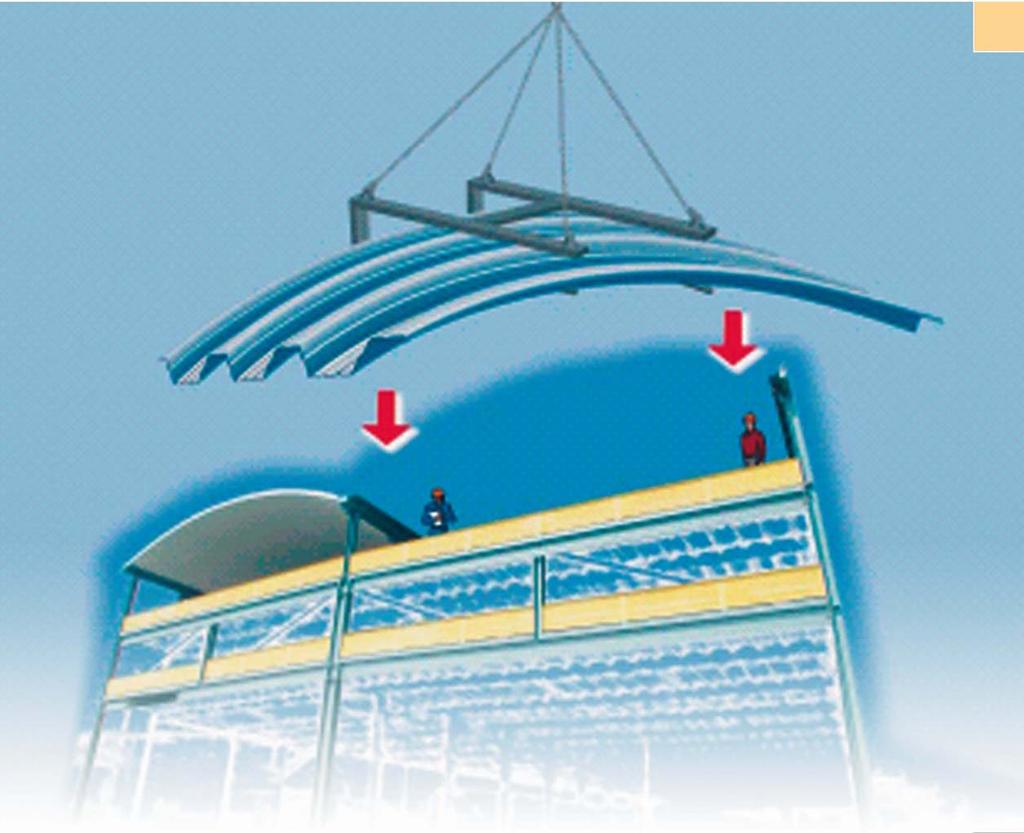
8 6. Installation of the arched roof 6.1 Single-shell roof system The most important step during the mounting work is the correct positioning of the first arched element. In general, the first arched element is fastened to an existing gable construction or gable wall. However, if the gable is not yet provided with bracings or filler material, it is also possible to mount the arched element in a way to be free-standing and self-supporting. In case of low buildings, the arched roof can be completely installed by using a fork lift. The loadbearing capacity at the end of the fork lift should be at least 500 kg. When using mobile cranes, an installation fork can be used as a lifting device. By means of such an installation fork, the first arched element is taken off the package and secured on the fork arms before being lifted (see sketch.). Securing is possible by means of a device integrated in the fork or by using screw clamps. page 6/24


9 The correct mounting direction is shown on the lay out plan. When swinging the first element into its position, one installer has to be present at each of the supporting points. The workers must be sufficiently secured, e.g. harnesses and/or scaffolding along the outer side of longitudinal beams in case of single-bay constructions, or railings mounted on the outer side of sufficiently large girders in case of multi-bay constructions as per the relevant national safety guidlines. page 7/24
, hot dip galvanized, with nut M 12 (DIN 6915) and 2 washers 12 (DIN 6916).")
10 After the first element has been swivelled into the correct position, it remains suspended on the installation fork untill all clamping plates have been inserted and slightly fastened by means of the retaining screws. Fastening material to be used: 1. Arched profile HP 41 B Hexagon head bolts M 12 x length (DIN 6914), hot dip galvanized, with nut M 12 (DIN 6915) and 2 washers 12 (DIN 6916). Specially coated clamping plates (Hoesch ref. no. S35-034), fastened in each chord (e = 160 mm) or in each second chord (e = 320 mm), see lay out plan. 2. Arched profile HP 107 B Hexagon head bolts M 16 x length (DIN 6914), hot dip galvanized, with nut M 16 (DIN 6915), 2 washers 17 (DIN 916). Specially coated clamping plates (Hoesch ref. no. S35-036), fastened in each chord (e = 250 mm), see layout plan. For fastening the clamping plates, the arched shells are provided with factory-made oblong holes on the supporting points. Ensure that the upper edge of the oblong holes lies on the screws. Hole size: Profil HP 41B: 14 x 20 mm Profil HP 107B: 18 x 35 mm page 8/24


11 Before finally tightening the fastening screws, the element must be exactly aligned by means of a crane. Then, a corded ladder is pulled over the bent face of the arched element and fixed on both ends. A third worker has to climb up to the crown to undo the clamps used for securing the element on the laying fork. During all this time, the crane must hold the fork under tension. The crane may only release the installation fork when the worker has left the arched element. Now, the fastening screws can be finally tightened. The most difficult part of the installation work has been done. page 9/24
12 The clamping plates have to be sealed all-around by means of silicon. A sealing tape 5 x 20 mm is stuck on the upper chord of the last chord. The second arched element is taken off the ground by means of the installation fork on the crane, clamped and swivelled into the correct position (as described above). After the element has been slightly fastened to the supports, one worker climbs on the already mounted arched shell to the crown, checks the ridge line and screws 1 to 5 connecting screws into the longitudinal joint, starting from the middle to both sides (for screw types, see next page). The larger the arc span, the more connection points are required. After having fastened the screws, the worker has to undo the clamps on the laying fork; then he returns to the ground. The crane releases the laying fork and swivells it away. The fastening screws in the clamping plates have to be tightened. The corded ladder has to be put onto the element mounted beforehand. Meanwhile, the next arched element is taken off the ground, and the installation procedure already described is repeated. In this way, the installation work is continued. After about every third panel (depending on the span), the vertical adjustment of the elements and the horizontal alignment of the ridge line have to be checked. The corded ladder and the scaffolding are to be repositioned in accordance with the progress of work. The installation work is continued in this manner until windows rows or other elements are planned to be installed. Openings for window rows are left open at this stage. Attention: Protect openings - danger of accident! Openings for skylights or other roof cutouts are made subsequently, after completion of the installation work. During installation, make sure that top hat profiles near cutouts are correctly positioned (see layout plan). Subsequent modification of their position is not possible, compare chapter 7. The installation work is continued until the complete shell is laid. At this time or earlier if additional personnel are available, the arched elements are additionally statiched together in their longitudinal joints. page 10/24
13 Fastening material to be used: stainless steel thread-cutting screws, e.g. EJOT JA3-6.5 x 24/19 E22, spacing: according to laying plan, generally e = 3 screws/m. The work is to be done from the corded ladder. After completion of the erection or if possible even parallel, other work has to be carried out, i.e. gutters, roof edges, plumbing. page 11/24

14 6.2 Double-shell roof system For mounting the inner shell, proceed as described in item 6.1. Exception: Stitching of the arched shells in their longitudinal overlaps is achieved by means of sealed rivets instead of special sealing screws as specified for single shells. Fastening material to be used: sealed rivets Ø 4,8 mm spacing: according to layout plan, generally e = 3 rivets/m page 12/24

15 Only use sealed rivets! In case of standard blind rivets, the pin may get lost, and the vapour tightness of the lower shell is no longer ensured. After completion of this work, permanent use of the crane is not necessary anymore. However, the crane will be required later for pulling up the arched elements for the outer shell. Beforehand, the longitudinal joints of the inner shell have to be selaed with a sealing tape on the external surface, in order to build up a vapour seal / convection seal. Use self-adhesive aluminium strips, width: 50 mm, e.g. Scotch aluminium tape, type 425, manufacturer: 3M. self-adhesive aluminium tape Next, the spacer profiles (= top hat profiles) are to be fastened. Before being installed, these have to be provided with the trapezoidal insulating wedges which are included in the delivery. It is advisable to start fastening at the supports and to continue towards the crown. The middle top hat profile has to be positioned exactly at the crown line. The position of the spacer profiles is shown in the layout plan. Material to be used for fastening the top hat profiles on the lower shell: sealed rivets Ø 4.8 x 9.0 AL (long system), for number and spacing, see layout plan page 13/24

16 Stick sealing tape 5 x 50 mm onto the hat profiles for thermal insulation. When all spacer profiles are completely mounted, the mobile crane is needed once again. Meanwhile, workers should have already split up the packages containing the outer shell elements into small units of 5 to 6 panels each. These small units are taken off the ground by means of the crane and pulled to the roof surface by means of the laying fork in a way that they are positioned on the hat profiles. The spacing corresponds to their number x element cover width. Finally, the crane is used to pull up the insulating material. After this work, the crane is no more needed and can be removed. The remaining work is done manually. First, the thermal insulation material has to be put onto the inner shell. In steep roof areas (edges), the insulating material must be fixed by means of selfadhesive fastening pins and safety washers. For position and number, pls. see laying plan. page 14/24

17 Immediately after this step, the cover shells are taken from the stack, placed onto the inner shell provided with insulating material and fastened on the hat profiles. Fastening material to be used: example: EJOT JA x 25 E16, stainless steel, number according to layout plan. In most cases, gutter sheets or similar folded parts along the eaves are to be mounted together with the roof shells. Particularities: In case of double-shell arched roof systems, - the longitudinal joints of the upper shell are generally not stitched, - generally, there are no clamping joints in the eaves' area. Attention: exceptions are possible! Always consult the layout plan. The remaining work is carried out as described in item 6.1. We once again emphasize the need of observing the minimum safety measures as described for the complete work. The safety equipment has to be removed and placed again in accordance with the progress of work. The present description is limited to descriptions of the main working processes and their routine execution. In practice, however, special requirements often have to be complied with. In general, such requirements can be clarified in an early phase on the basis of the standard procedures as described, i.e. when preparing the layout plan, so that adequate detail solutions allow the mounting work to be carried out without problem. page 15/24

18 7. Skylight / Smoke and heat outlets 7.1 Important hints: When cutouts in the Hoesch arched roof are required for skylights, smoke and heat outlets or trap doors always consult the structural engineer (in charge of the structural analysis of the arched roof). Cutouts in areas of the load-bearing arched shell will destroy its load-bearing function, and adjacent profiles will have to take over this additional load-bearing function which requires special measures. In any such case, a structural analysis is necessary. Generally, only skylights with a maximum width of 1.20 m (90 to the chord direction) can be installed. Please observe the regulations for prevention of accidents. 7.2 Frames The frames have to be adapted to the profile of the arched shells. Available versions: for installation in the crown of the roof installation adjacent to the crown of the roof The frames consist of welded aluminium sheet. They are proposed as single shell version, non insulated and double shell version, insulated. The upper edges have to be adapted to the types of skylight to be installed. page 16/24
19 7.3 Single-shell roof system In case of the single-shell roof system, load-bearing steel frames have to be installed. Such frames are visible from the building inside. For the installation of the skylight frames, see items and Double-shell roof system The openings for skylight frames are generally cut into the completed roof. So when installing the hat profiles please bear in mind that they are taken as load-bearing frames. For the correct position and the required material thickness of the hat profiles, see the laying plan Installation in the crown (ridge) Basic data: skylight width = 1,200 mm skylight length = 1,200 / 1,800 / 2,400 mm profile: HP 41B Working steps: see Diagrams Marking of the opening on the external shell Width: 1,540 mm Length: L mm, see Diagrams. 4 and 5 2. Cutting of the outer shell by means of a compass saw. The cutting depth must be such that only the outer shell is cut without getting into contact with the inner shell. Observe the stroke of the compass saw, shorten the saw blade, if necessary. 3. Remove cut parts. 4. Remove thermal insulation. page 17/24
20 5. Mark inner shell and cut it out. Width: 1,200 mm Length: L + 20 mm, see Diagrams 4 and Mount wooden planks, see Diagram Mount factory-prepared edge profiles, see Diagrams 4 and Bend up the trapezoidal profile lower chord of the outer shell, see Diagram Stick on sealing tapes 5 x 20, see Diagram Put profile filler onto the outer shell, see Diagrams 3 and Mount framing and fasten it to the outer shell through each upper chord. Fasten the lateral chords to the outer shell by means of 5 screws. Fastening material to be used: i. e. EJOT JA 3-6,5 x 24/19 E 16, stainless steel. page 18/24
21 page 19/24
22 7.4.2 Installation adjacent to the crown Basic data: skylight width = 1,200 mm skylight length = 1,200 / 1,800 / 2,400 mm see Diagrams 10 and 11 Working steps: see Diagrams 7 through Marking of the opening on the outer shell Width: 1,540 mm Length: L mm 2. Cutting of the outer shell by means of a compass saw. The cutting depth must be such that only the outer shell is cut without getting into contact with the inner shell. Observe the stroke of the compass saw. Shorten the saw blade, if necessary Attention: The opening for inserting the framing must also be cut, see Diagram Remove cut parts. 4. Remove thermal insulation. 5. Mark inner shell and cut it out. Width: 1,200 mm Length: L + 20 mm, see Diagrams 10 and Mount wooden planks, see Diagram Mount factory-prepared edge profiles, see Diagrams 10 and 11. page 20/24
23 8. Up the trapezoidal profile lower chord of the outer shell, see Diagram Stick on sealing tapes, see Diagram Put profile filler onto the outer shell, see Diagram Slide framing into the opening on the ridge side, see Diagrams 10 and Put 2 profile fillers on the flat upper edge of the framing, below the arched sheet on the ridge side, see Diagrams 10 and Fasten framing through each upper chord. Connect lower chord of the arched sheets on the ridge side with the framing, fasten the lateral chords to the outer shell by means of 5 screws. Fastening material to be used: i. e. Ejot lja3-6.5 x 24/19 E 16, stainless steel, See Diagrams 10, 11, 12 & Stick on sealing tapes 5 x 20 for closing chord. Position closing chord and fasten it. For screws, see item 13. See Diagram 13. page 21/24
24 Bild 12: page 22/24
25 8. Accessories D e s i g n a t i o n Ref. no. Clamping plate profile HP 41B S profile HP 107B S S Profile filler profile HP 41B S profile HP 107B S Verge profile, bent: cut to length 340 mm S cut to length 440 mm S cut to length 540 mm S Top hat profile: thickness 1,00 mm S thickness 1,50 mm S thickness 2,00 mm S Other flashings have to be ordered as special flashings. In this case, a sketch of the cross section is required. page 23/24
 84 51-230 E-mail: office@hoesch.at Internet: www.hoesch.at 2013/06 page 24/24")
26 Hoesch Bausysteme GmbH Neumarkter Straße Scheifling Österreich Telephone: +43 (3582) Telefax: +43 (3582) Internet: /06 page 24/24
GLOSSARY OF TERMS SECTION 8
 GLOSSARY OF TERMS SECTION 8 Anchor Bolt Angle Base Plate Bay Blocking CCB Centerline Chord Cladding Clip Closure Strip An A-307 steel bolt embedded in the concrete footing to anchor the base plate of the
Dura-Lock Roof System
 DLR-14 Dura-Lock Roof System Assembly and Installation Instructions Read the instructions before starting the job. They explain the steps required to produce a finished product that will meet factory specifications.
INSTALLATION INSTRUCTIONS ROPE ASSEMBLIES FATZER AG WITH HYEND SOCKETS FOR FROM. Kai-J. Thiem (THK) Martin Bechtold (BEM)
 Martin Bechtold (BEM)") INSTALLATION INSTRUCTIONS FOR ROPE ASSEMBLIES WITH HYEND SOCKETS FROM FATZER AG Created Kai-J. Thiem (THK) Checked Martin Bechtold (BEM) Released Kai-J. Thiem (THK) Version 2.0 Date 30.08.2016 Proof of
INSTALLATION INSTRUCTIONS FOR ROPE ASSEMBLIES WITH HYEND SOCKETS FROM FATZER AG Created Kai-J. Thiem (THK) Checked Martin Bechtold (BEM) Released Kai-J. Thiem (THK) Version 2.0 Date 30.08.2016 Proof of
METHOD STATEMENT FOR THE CONSTRUCTION OF LIGHTWEIGHT HALLS
 METHOD STATEMENT FOR THE CONSTRUCTION OF LIGHTWEIGHT HALLS General The exact position of the structure has to be established. Please note that the difference in height must not exceed 1.5% in longitudinal
Verge Flashing. Verge Flashing. Only use if flashings requirements can be site measured before ordering. Verge Clip
 Tolerance Detail (recommended) Verge Closure Verge Channel Verge Clip Verge Flashing VERGE CHANNEL RIVETTED TO EUROSEAM AT APPROX 400MM CENTRES USING 4.8 X 12MM RIVETS. NB: DO NOT RIVET AT HALTER POSITION
INSTALLATION INSTRUCTIONS TRI-ROOF. energy for a better world
 energy for a better world INSTALLATION INSTRUCTIONS TRI-ROOF The flexible roof integration system Compatible for framed module types* Simple exchange of modules Replaces existing roofing Special profiles
lindab we simplify construction LindabSandwichPanels Installation instructions PIR Panels
 lindab we simplify construction LindabSandwichPanels Installation instructions PIR Panels Assembly instructions Before you start Check that the panel support structures are level. Position the packages
Five Star Panel Installation Instructions
 Five Star Panel Installation Instructions How to Store Five Star Panels You will need to store FIVE STAR PANELS in dry place to prevent staining, deterioration and possibly void all warranties. Stand the
PUSH-PULL-PROPS. and accessories ROBUSTA-GAUKEL GMBH MOUNTING TECHNOLOGY &CO.KG
 PUSH-PULL-PROPS and accessories MOUNTING TECHNOLOGY ROBUSTA-GAUKEL GMBH &CO.KG MOUNTING TECHNOLOGY PUSH-PULL-PROPS AND ACCESSORIES INDEX General information...................... 3 Push-pull-prop Type
SILVERBACK INSTALLATION MANUAL
 SILVERBACK INSTALLATION MANUAL R-SERIES SOLAR RACKS T OLL FREE 866-766-3727 WWW.ROOFSCREEN.COM Introduction... 2 The Silverback Solar Racking System... 2 This manual... 2 Application... 2 System Overview...
Installation Manual. Last Updated 4 February, Postal PO Box 932 Bayswater VIC
 Installation Manual Last Updated 4 February, 2013 Part 1: Provided Material The Panel Expandable Foam Sealing Strip Barge Capping Z-Fascia Structural Screws Timber: 3/8 head size Metal: 5/16 head size
DUTCH GABLE FREESTANDING CARPORT
 DUTCH GABLE FREESTANDING CARPORT STRATCO OUTBACK ASSEMBLY INSTRUCTIONS. Your complete guide to building a FREESTANDING Outback DUTCH GABLE CARPORT BEFORE YOU START Carefully read these instructions. If
FischerTHERM plusdach The Sandwichelement with the special something
 The Sandwichelement with the special something Contents Page General Product Range 4 Fasteners 5 Secure fastening 7 Assembly 8 9 Details 0 References 4-5 FischerProfil 05 FischerTHERM plusdach The first
Steel Sound Enclosure
 Steel Sound Enclosure INSTALLATION MANUAL List of tools recommended for use during installation: vise grips c clamp ladder electric drill drill bits / taps as req d screw drivers hammer rubber mallet pipe
GROWING BETTER THROUGH DESIGN. 6ft Lean-To LEAN-TO. Assembly Instructions 04/02
 GROWING BETTER THROUGH DESIGN 6ft Lean-To LEAN-TO Assembly Instructions 04/02 6ft Lean-To Greenhouse Base Plan Introduction/Tools/Contents / / Contents This is a copy of our Lean-To greenhouse base plan.
February 2004 RONDA. Circular Formwork Instructions for assembly and use
 February 2004 Circular Formwork Instructions for assembly and use Table of Contents Product Features 2 General Survey 3 Components 4 7 Measures of Ronda Elements 8 9 Adustment of Radii 10 11 Connections
 SUPREME WALL GARDEN ASSEMBLY INSTRUCTIONS 24/08/16 www.hallsgreenhouses.com Please refer to website for the most up to date instructions. SAFETY WARNING 1. Always wear protective glasses, shoes, gloves
CURVED ROOF ASSEMBLY INSTRUCTIONS ATTACHED VERANDAH. Your supplementary guide to building an ATTACHED CURVED ROOF VERANDAH or PATIO BEFORE YOU START
 ROOF ATTACHED VERANDAH ASSEMBLY INSTRUCTIONS Your supplementary guide to building an ATTACHED ROOF VERANDAH or PATIO This set of instructions should be used in conjunction with the Stratco instruction
CINTRALUX ALU BARREL VAULT EP 10/10
 CINTRALUX ALU BARREL VAULT EP 10/10 Installation instructions EN 14963 Artn 43984 E_MH_Cintralux EP 10/10 mm AG.PLASTICS QUALITY 1 Installation instructions Cintralux aluminium barrel vault: Cintralux
Installation Manual for Gate Guard
 Installation Manual for Gate Guard Fast Opening Barrier Gate for Emergencies and Contra Flow Innovative safety technology from SGGT of Germany TABLE OF CONTENTS Page Number Preface 3 Introduction 3 System
CEILING-MOUNTED MONORAIL ANCHOR TRACK SYSTEM Assembly and Operation Instruction Manual
 CEILING-MOUNTED MONORAIL ANCHOR TRACK SYSTEM Assembly and Operation Instruction Manual This manual is for various mounting types and plain and trussed track profiles. ISO 9001:2008 Registered Manual 103-0075
Installation Instructions - Model V4JSD 1
 Installation Instructions - Model V4JSD 1 Support Assemblies: Parts list: (Note see enclosed cut sheet for quantities and dimensional information) A vertical structural member (1 ½ x 1 ½ modular frame)
Tech Sheet. T4 Interior conversion kit how to - fitting instructions. 1. Rear seat belts. 2.
 Page 1 of 8 T4 Interior conversion kit how to - fitting instructions Thank you for purchasing our T4 interior conversion kit. This kit will enable you to convert any SWB left hand loading door T4 into
Fig. 2 DORMA-Glas Stand/Issue 02/03 Seite/Page 1/7
 FSW Installation instructions Track rail 75 x 72 mm 1. Ceiling substructure and installation of the track rail (Fig. 1): The track rail must be bolted over its entire length (including the stacking track
INSTALLATION GUIDE SLIMLINE ROOF LANTERN 4 PANE CONFIGURATION
 INSTALLATION GUIDE SLIMLINE ROOF LANTERN 4 PANE CONFIGURATION SLIMLINE STEP-BY-STEP INSTALLATION GUIDE Thank you for choosing Roof Maker, we hope you are delighted with your new rooflight. Our roof lanterns
MARQUEE INSTALLATION HANDBOOK. Curved Structures
 MARQUEE INSTALLATION HANDBOOK Curved Structures 12m Curved Roof Beam Assembly Instructions Ensure there are no overhead or underground obstructions or services before starting to assemble frame. Square
INSTALLATION INSTRUCTIONS
 1 INSTALLATION INSTRUCTIONS Prior to Assembling and Installing: 1) Field Check and verify that all components of the structure required for installation are in place per the approved shop drawings. Report
Assembly instructions
 Commission: Order no.: Rondo Pavilion PR Ø3.9 Technical changes reserved Assembly instructions As at: 05.011 Sliding door Dear Garden lover, we congratulate you on the purchase of a quality product from
GABLE ROOF CARPORT RECOMMENDED INSTRUCTION MANUAL
 GABLE ROOF CARPORT RECOMMENDED INSTRUCTION MANUAL Table of Contents Introduction 2 Components 3 Step 1a Marking out the Perimeter of the Carport with Footing only 3 Step 2a Footing Set-Out for Concrete
SILVERBACK INSTALLATION MANUAL
 SILVERBACK INSTALLATION MANUAL S-SERIES SOLAR RACKS T OLL FREE 877-765-2759 WWW.SILVERBACKSOLAR.COM Introduction... 2 The Silverback Solar Racking System... 2 This manual... 2 Application... 2 System Overview...
TOLL FREE:(888) FAX:(941) ASSEMBLY of ProTEC CONCRETE STRUCTURAL INSULATED PANEL
 FAX:(941) ASSEMBLY of ProTEC CONCRETE STRUCTURAL INSULATED PANEL") ASSEMBLY of ProTEC CONCRETE STRUCTURAL INSULATED PANEL The ProTEC panels are manufactured with grooves on all four sides to accept the steel components. This grooving applies to the regular panel whose
ASSEMBLY of ProTEC CONCRETE STRUCTURAL INSULATED PANEL The ProTEC panels are manufactured with grooves on all four sides to accept the steel components. This grooving applies to the regular panel whose
INSTALLATION INSTRUCTIONS TRI-VENT. energy for a better world
 energy for a better world INSTALLATION INSTRUCTIONS TRI-VENT The photovoltaic mounting system for trapezoidal sheet roofs Quick and easy installation Riveting instead of glueing Securing without screws
Ledger Board Lean-to Instruction Manual
 Ledger Board Lean-to Instruction Manual for 18 x 24 2 x 8 /12 6 covers ROOF ONLY ROOF WITH GABLES 2-SIDED FRAME ONLY 2-SIDED WITH GABLES Our unique assembly process quickly transforms the individual pieces
E N G L I S H GARDEN SHED. Assembly Instructions. Suitable for Models WITH VARYING DEPTHS
 GARDEN SHED Assembly Instructions Suitable for Models 6' Wide 8' Wide 0' Wide WITH VARYING DEPTHS GI0003 November 0 INSTALLATION ADVICE It's Not That Difficult! The construction of your shed isn't as complicated
Roof Only Lean-to Instruction Manual
 Roof Only Lean-to Instruction Manual for 10 x 20 2 x 8 /10 6 covers Our unique assembly process quickly transforms the individual pieces into a finished structure that will give you a lifetime of service.
SpeedDeck. Fixing and Handling Guide
 SpeedDeck Section 1 Delivery/Storing On Site/Handling l SpeedDeck is factory or on-site manufactured. l Straight SpeedDeck bundles are a maximum 1 tonne, sheets nestled and banded with polypropylene or
H20 Beam for Elevated Slabs Application Guide
 H20 Beam for Elevated Slabs Application Guide A WORD ABOUT SAFETY High productivity depends on safety; even a minor accident causes job delays and inefficiency, which run up costs. That s why Symons, in
MevaDec. Contents. Ref. No. Description / Application Product m² list kg
 Ref. No. Description / Application Product m² list kg This product list includes all parts necessary for most applications. For parts required for special applications, please refer to the MEVA price list.
Assembly Instructions 10 X 10 Aluminum Frame Building
 Assembly Instructions 10 X 10 Aluminum Frame Building 27 97 9 8 47 36 74 52 10 10 X 10 Square Building W/ Dome Includes: The Steel Entry Door with a Dead Bolt Lock assembly and Aluminum Door Frame. Metal
Inclined Roof System Trimoterm SNV
 Inclined Roof System Trimoterm SNV Inclined Roof System Trimoterm SNV - Technical Document EN Version 6 July 2016 TABLE OF CONTENTS 1 Technical Description of Roof System Trimoterm SNV 1 1.1 General 1
Edgerail Aluminum Bridge Railing System Specification & Installation Instructions
 Edgerail System Specification & Installation Instructions Hill & Smith, Inc 1000 Buckeye Park Road Columbus, Ohio 43207 Tel: 614-340-6294 Fax: 614-340-6296 www.hillandsmith.com Section A System Specification
Installation Instructions
 Installation Instructions SOLC 220 SOLC 220 PAG SOLC 220 PAE SOLC 220 BAG SOLC 220 BAE Flat plate collector Basic kit Frankfurt tile Extension kit Frankfurt tile Basic kit plain tile Extension kit plain
CAMSPAN GALLERY CONVEYORS INSTALLATION & ERECTION GUIDELINES
 CAMSPAN GALLERY CONVEYORS INSTALLATION & ERECTION GUIDELINES JANUARY, 1998 Cambelt International Corporation 2820 West 1100 South Salt Lake City, Utah 84104 Phone(801) 972-5511 Fax(801) 972-5522 www.cambelt.com
FS Uno mounting instructions. 2 Pile driving (Ramming) 5. 6 Components list Torque specifications 15
 5. 6 Components list Torque specifications 15") FS Uno System Mounting instructions CONTTS Page 1 General - Safety, planning and tools 2 2 Pile driving (Ramming) 5 3 Rack overview - Components and fasteners 6 4 Mounting of the individual assembly groups
FS Uno System Mounting instructions CONTTS Page 1 General - Safety, planning and tools 2 2 Pile driving (Ramming) 5 3 Rack overview - Components and fasteners 6 4 Mounting of the individual assembly groups
Ledger Board Lean-to Instruction Manual
 Ledger Board Lean-to Instruction Manual for 18 x 24 2 x 8 covers Our unique assembly process quickly transforms the individual pieces into a finished structure that will give you a lifetime of service.
PRODUCT INFORMATION MANUAL SECTION: 16 FIXED METAL AWNINGS FIXED METAL AWNINGS
 FIXED METAL AWNINGS Fixed Metal Awnings BAHAMA Maximum Width Minimum Width Minimum projection Minimum Drop TS - Truss Support Maximum Overhang Minimum Overhang Unlimited 500mm TS=1601mm PS=2847mm PS=
FischerTHERM plusdach
 FischerTHERM plusdach * An enterprise of Corus Building Systems FischerTHERM plusdach concealed fastening The FischerTHERM plusdach roof, with the Fischer plus-rail The FischerTHERM plusdach roof can
ASSEMBLY INSTRUCTIONS. Construction type approved Reg. no S819 F ENERGY AND SANITARY SYSTEMS
 Heliostar 252 S4 and 218 S4 FREE-STANDING INSTALLATION vertical ASSEMBLY INSTRUCTIONS Construction type approved Reg. no. 011-7S819 F ENERGY AND SANITARY SYSTEMS Safety instructions Safety instructions
Deauville Installation Guide
 vjul16 (for 17 or 24 mm Surface Wall Profiles) DO NOT ASSEMBLE WITHOUT FULLY READING THESE INSTRUCTIONS Page 2 Thank you for purchasing this Deauville shower enclosure. Please study these instructions
Gable HomeshedsTM INSTALLATION BEFORE YOU START TOOLS REQUIRED GUIDE LARGE SPAN. Council Approval. Before Starting
 INSTALLATION GUIDE Gable HomeshedsTM LARGE SPAN BEFORE YOU START Council Approval It is important to contact your local council before building your Stratco Gable Homeshed. You will have already received
Meva Guided Screens MGS Technical Instruction Manual
 Meva Guided Screens MGS Technical Instruction Manual Product Characteristics: The MEVA Guided Screens (MGS) system encloses complete floors especially in high-rise construction independent of the height
GIRTS ON BACK OF BUILDING
 GIRTS ON BACK OF BUILDING ALL GIRTS ARE 1 1/2 SQUARE TUBE. GIRT LENGTHS FOR 12, 20, 24, AND 30 WIDE BUILDINGS: ON 12 WIDE BUILDINGS GIRTS ARE 67 3/4 LONG ON 20 WIDE BUILDINGS GIRTS ARE 56 3/4 LONG ON 24
Instructions for Installation on a Pitched Roof LIGHTWAY optical tube LW 260, LW 320, LW 520, LW 760
 Lightway, s.r.o. Registered office: Ledvinova 1714, 149 00 Praha 4 Offices: Za Humny 1054/4a, 161 00 Praha 6 tel.: 235 300 694, fax: 235 300 218 Company ID No.: 63669366, Tax ID No.: CZ63669366 Bank: KB
Installation Instructions for Vista Air Vertically Folding Walls
 Installation Instructions for Vista Air Vertically Folding Walls Use these instructions in conjunction with your shop drawings to see the specifics that are particular to the model you are installing.
GUARDRAIL ALUMINIUM SECURIGARD
 GUARDRAIL ALUMINIUM SECURIGARD ZZNO041UK April 2018 REQUIRED TOOLS Metal shears ( to remove the pallet bindings) Metal saw/batterypowered grinder Mallet Tape measure Cord Screwdriver Rivet gun CAUTION:
TRADITIONAL GABLE ATTACHED PATIO AND CARPORT. Your complete guide to building an ATTACHED Outback TRADITIONAL GABLE PATIO or CARPORT
 TRADITIONAL GABLE ATTACHED PATIO AND CARPORT STRATCO OUTBACK ASSEMBLY INSTRUCTIONS. Your complete guide to building an ATTACHED Outback TRADITIONAL GABLE PATIO or CARPORT BEFORE YOU START Carefully read
DUTCH GABLE CARPORT RECOMMENDED INSTRUCTION MANUAL
 DUTCH GABLE CARPORT RECOMMENDED INSTRUCTION MANUAL Table of Contents Introduction 2 Components 3 Step 1a Marking out the Perimeter of the Carport with Footing only 4 Step 2a Footing Set-Out for Concrete
S H E D A S S E M B L Y I N S T R U C T I O N S
 T I T A N R A N G E S H E D A S S E M B L Y I N S T R U C T I O N S 8 X 10 ft Approx = 2550 x 3140 cm COMPONENT LIST Component illustrations are given as a visual guide only and are not in proportion PART
SecuAnch Roof Anchor System
 Height Safety Products Email: marketing@fallprotec.com SecuAnch Roof Anchor System 1 Presentation The SecuAnch lifeline is designed to be permanently installed on buildings and other structures where maintenance
Manual for Shelter W3,5xL8,0xH3,8m
 Manual for Shelter W3,5xL8,0xH3,8m 22-11-2016 Congratulations on your purchase of our instant shelter. This unit is a combination of excellent manufacturing and design. It is comprised of a rigid frame
Installation Instructions
 Installation Instructions Alpha SolarSmart On Roof Kits for the Installation of Alpha Solar Collectors onto Tile and Slate Type Roofs For Technical help or for Service call... ALPHA HELPLINE Tel: 0 77
ATLANTIS RAIL Contact Information
 ATLANTIS RAIL Contact Information Customer Service (800) 541-6829 (508) 732-9191 Spectrum System Installation Instructions Atlantis Rail s Spectrum System is an easy to install, universal cable railing
Connect Transit Shelter
 Tools Required *denotes special tools required Connect Shelter, 8ft Connect Shelter, 12ft *Soft, non abrasive protective surface such as a furniture blanket *Source of compressed air (for thorough dust
TELESCOPIC GATE MANUFACTURING AND INSTALLATION MANUAL.
 TELESCOPIC GATE MANUFACTURING AND INSTALLATION MANUAL. Telescopic gates have been manufactured for many years essentially in the same way they are largely today. In recent years hardware suppliers have
AWNING / PATIO COVER INSTALLATION INSTRUCTIONS
 AWNING / PATIO COVER INSTALLATION INSTRUCTIONS Before You Begin Read the installation instructions thoroughly before beginning the installation procedure. Perspective In the Awning Instructions, Back means
Polytegola N. Bitumen Roof shingles. Application guide
 Polytegola N Bitumen Roof shingles Application guide Application manual POLYTEGOLA N CONTENT 1. Foreword - General conditions 3 2. POLYTEGOLA N designs 4 3. Roof pitches 5 4. Storage 5 5. Roof decking
10 Octagon Cedar Gazebo Assembly Instructions
 10 Octagon Cedar Gazebo Assembly Instructions Toll Free: 866.768.8465 Hours: 9-5 Monday-Friday EST www.homeplacestructures.com Package ships as shown revised 06/22/09 10 Cedar Gazebo Assembly Instructions
Copyright 2008 Robert Conroy
 Copyright 2008 Robert Conroy 24 Diameter Dome This is a precision structure. One must use precise jigs in its fabrication. The measurement tolerances are 1/32", while the overall tolerances are 1/16".
MANUAL MOUNTING SYSTEM FOR BITUMEN / EPDM
 MANUAL MOUNTING SYSTEM FOR BITUMEN / EPDM EN mounting system for insulated pitched roof Bitumen / EPDM for solar panels landscape setup ESDEC BV 2015 TABLE OF CONTENT 1. Introduction 1 2. General installation
Stratco Sanctuary INSTALLATION BEFORE YOU START TOOLS REQUIRED GUIDE
 INSTALLATION GUIDE Stratco Sanctuary Verandahs, Patios and Carports BEFORE YOU START It is important to check with your Local Government Authority prior to the installation of your new Stratco Sanctuary
Installation Instructions for Solar Snow Pad (SSP-T-3)
") Installation Instructions for Solar Snow Pad (SSP-T-3) Warning- Do not use this product on solar arrays where the calculated array snow loads exceed 50 pounds per square foot (psf). Most solar panels are
Installation Instructions for Solar Snow Pad (SSP-T-3) Warning- Do not use this product on solar arrays where the calculated array snow loads exceed 50 pounds per square foot (psf). Most solar panels are
RH-412 STEEL DOORS INSTALLATION INSTRUCTIONS
 RH-412 STEEL DOORS INSTALLATION INSTRUCTIONS By following the steps outlined below, the assembly, installation and adjustment of the steel doors, will be a simple process. Let s start with the Driver Side.
Taurean Sectional Garage Door INSTALLATION INSTRUCTIONS
 BEFORE YOU BEGIN MAKE SURE THESE INSTRUCTIONS ARE READ AND UNDERSTOOD COMPLETELY. THESE INSTRUCTIONS ARE INTENDED FOR PROFESSIONAL GARAGE DOOR INSTALLERS. ALL REFERENCES ARE TAKEN FROM THE INSIDE LOOKING
CountryAccents Pergola Assembly Instructions
 CountryAccents Pergola Assembly Instructions Options 11 2" Squares Lattice Railing Gingerbread Scroll (For 5" Posts Only) Site Preparation Site preparation for either the round column or the 5" post pergola
6.1. PUSH-PULL-PROPS and accessories
 6 6.1. PUSH-PULL-PROPS and accessories MOUNTING TECHNOLOGY 6 GENERAL INFORMATION PUSH-PULL-PROPS AND ACCESSORIES INDEX General information....................... 3 Push-pull-props Type R.....................
Installation. ng Kitt
 Installation Instructions Alpha SolarSmart 100 Roof Integrated Flashi ng Kitt for the Installation of Alpha Solar Collectors into Tiled Roofs 1 Integrated Flashing kit for Alpha SolarSmart 1000 CONTENTS
Page No. 1 of 15. Issue F: 11/ FI
 MY09 FORESTER SUV CARGO BARRIER Installation Instructions Part Number 705400/425 705400 -To Suit Non Sunroof models only 705425 To suit Sunroof models only Production From March 2008 to Dec. 2012 This
Instructions for Installation on a Flat Roof
 Lightway, s.r.o. Registered office: Ledvinova 1714, 149 00 Praha 4 Offices: Za Humny 1054/4a, 161 00 Praha 6 tel.: 235 300 694, fax: 235 300 218 Company ID No.: 63669366, Tax ID No.: CZ63669366 Bank: KB
Assembly instructions Pantograph shutters
 Assembly instructions Pantograph shutters Read these instructions, observe the contents and the warning notes prior to assembly. The information is very important for installation and correct use of the
STACKING MULTI-SLIDE DOOR SYSTEM INSTALLATION INSTRUCTIONS
 STACKING MULTI-SLIDE DOOR SYSTEM INSTALLATION INSTRUCTIONS 1290363 Revision 1 12/16 Page 1 Weather Shield Mfg., Inc. NOTICE CAUTION! Failure to install and maintain our product according to these instructions
Installation Manual. This installation is for the Odyssey H1800 Series Ventilation System.
 Installation Manual This installation is for the Odyssey H1800 Series Ventilation System. This installation is limited to roofs with pitches between 3 and 35. This instruction assumes that there is a power
Installation Guide (888)
") BamDeck Installation Guide (888) 788-2254 The Collection Decking Systems BAMDECK 3G 5-7/16 Wide Plank Dims: 96 L x 5-7/16 W x 13/16 H BAMDECK 3G 16FT. 5-7/16 Wide Plank Dims: 192 L x 5-1/2 W x 13/16 H
BamDeck Installation Guide (888) 788-2254 The Collection Decking Systems BAMDECK 3G 5-7/16 Wide Plank Dims: 96 L x 5-7/16 W x 13/16 H BAMDECK 3G 16FT. 5-7/16 Wide Plank Dims: 192 L x 5-1/2 W x 13/16 H
BioPrism Solid Surface
 Please read all instructions before installing products. These instructions are intended for use with InPro s standard toilet partitions, which include 58 high doors and wall panels, when deviating from
Balustrade Systems / Installation Instructions
 A. PARTS AND SUPPLIES NEEDED FOR INSTALLATION Hardware included for each 10 section of rail: 2 3 x 1-1/2 L-brackets 4 1-3/4 x 3/16 Blue hex-head screws for anchoring the L-brackets to the newel cap, column
MANUAL MOUNTING SYSTEM FOR CORRUGATED ROOF
 MANUAL MOUNTING SYSTEM FOR CORRUGATED ROOF EN mounting system for corrugated roof for solar panels in portait setup (cross-system) ESDEC BV 2015 TABLE OF CONTENT 1. Introduction 1 2. General installation
PATIO INSTALLATION MANUAL
 PATIO INSTALLATION MANUAL A few minutes spent reviewing the following instructions will help insure quick and proper assembly. The Patio Sauna Kit will arrive on a stretchwrapped pallet including pre-built
SunTrackerTwo Preparation
 TOLL FREE:(888)29-2705 FAX:(941)77-9460 info@eco-smart.com SunTrackerTwo Preparation Cutting Holes and Preparing Curbs T.G.I Or Truss CIRALIGHT INSTALLATION MANUAL Page 1 Cutting Holes and Preparing Curbs
Installation Instructions
 Supafold Slide Aside System Three Fold Room Divider Installation Instructions Distinctive Doors Ltd Supafold Slide Aside Internal Folding System IMPORTANT: Before proceeding with the installation, and
Mounting systems for solar technology
 Mounting systems for solar technology ASSEMBLY INSTRUCTIONS Roof Fastener System CrossHook 2G GB Table of contents TABLE OF CONTENTS THE COMPANY SAFETY REGULATIONS MATERIALS REQUIRED TOOLS REQUIRED ASSEMBLY
Gambrel Barn Construction Manual 8x8 through 16x24 Units
 Gambrel Barn Construction Manual 8x8 through 16x24 Units Tools Needed: Cordless drill (12V or higher) #2 square drive bit Hammer 6 step ladder Tape measure Square utility knife w/ blade & hook blade Little
Portofino Installation Guide
 vjul16 (for 17 or 24 mm Surface Wall Profiles) DO NOT ASSEMBLE WITHOUT FULLY READING THESE INSTRUCTIONS Page 2 Thank you for purchasing this Portofino shower enclosure. Please study these instructions
INSTALLATION GUIDE. Flat Roof Homesheds TM. Onto Concrete BEFORE YOU START TOOLS REQUIRED
 INSTALLATION GUIDE Flat Roof Homesheds TM Onto Concrete BEFORE YOU START It is important to check your Local Government Authority requirements before the installation of your new Stratco Flat Roof Homeshed.
Installation Guide Simplicity Alfresco. V1.9 Lu070318
 0333 305 5272 www.canoports.co.uk Installation Guide Simplicity Alfresco V1.9 Lu070318 Tools Required Below is a list of tools that you will require to install your the Simplicity Alfresco System. Cordless
STOP. V00029AC Rev. 04 READ ALL OF THE FOLLOWING INSTRUCTIONS BEFORE REMOVING CABINET FROM SKID TOOL LIST. NET-ACCESS S-Type Network Cabinets
 Rev. 04 STOP READ ALL OF THE FOLLOWING INSTRUCTIONS BEFORE REMOVING CABINET FROM SKID NET-ACCESS S-Type Network Cabinets -Phillips screwdriver -Flatblade screwdriver -22mm socket wrench -15mm socket wrench
Method of Build 1. Fire. Sound
 Method of Build 1 General Viso Fire & Acoustic in the solid form differs from most other systems as it can be erected using 12.5mm & 15.0mm boards within the same Aluminium framework. Also hidden fix board
Installation Instructions
 Installation Instructions Roof edge trim profile Series TAG multi-piece aluminium profile Front face height: 250-1050 mm supplied with patented 4F brackets as standard height-adjustable, horizontally moveable,
E-Z BUILD STEEL BARN 12' 12' 12' 16' 12' 20'
 E-Z BUILD STEEL BARN 12' 12' 12' 16' 12' 20' BUILD You can construct your own E-Z frame barn with the help of this step by step guide. North American softwood dimensional lumber sizes: Nominal Actual in
Chapter 23. Garage Construction
 Chapter 23. Garage Construction 23.1 ESTABLISHING CHALK LINES 23.2 MEASURING AND CUTTING WALL PLATES 23.3 MARKING WINDOW & DOOR LOCATIONS ON EXTERIOR WALL PLATES 23.4 MARKING STUDS ON EXTERIOR WALL PLATES
Assembly Instructions 10 X 10 Aluminum Roof Support
 Assembly Instructions 10 X 10 Aluminum Roof Support Aluminum Roof Support Bolt Package 16-5/16 X 2 ¼ SS Bolt 24-5/16 X 1 SS Bolt 40-5/16 SS Nylon Lock Nuts 16-5/16 SS Flat Washers 28-4 ½ Wood Screws 36-1
Wall flashing profiles FP 60 WA 1 WA 150 WA 1 - ÜK WA 1 - Ü 150 E
 Wall flashing profiles FP 60 WA 1 WA 150 WA 1 - ÜK 150-275 WA 1 - Ü 150 E 1 F Ü R D I E ZU K U N FT G E DAC HT. The alwitra waterproofing system alwitra wall flashing profiles are part of the practically