H20 Beam for Elevated Slabs Application Guide
|
|
|
- Charles Curtis
- 6 years ago
- Views:
Transcription


1 H20 Beam for Elevated Slabs Application Guide
2 A WORD ABOUT SAFETY High productivity depends on safety; even a minor accident causes job delays and inefficiency, which run up costs. That s why Symons, in the design of its systems and products, makes the safety of those people who will be working with and near the equipment one of its primary concerns. Every product is designed with safety in mind, and is tested to be certain that it will perform as intended with appropriate safety allowances. Factory-built systems such as these provide predictable strength, minimizing the uncertainty that often surrounds hand-made, job-shop and job-built equipment. As a result, Symons products are your best assurance of a safe operation when used properly. To insure proper use, we have published this application guide. We recommend that all construction personnel who will be involved, directly or indirectly, with the use of this product be familiar with the contents of this guide. As a concerned participant in the construction industry, Symons also recommends that regular safety meetings be held prior to starting the forming operation, and regularly throughout the concrete placement, form stripping and erection operations. Symons personnel will be happy to assist in these meetings with discussion of safe use of the equipment, slide presentations and other formal safety information provided by such organizations as the Scaffolding, Shoring and Forming Institute. In addition to the above meetings, all persons involved with the construction should be familiar and in compliance with applicable governmental regulations, codes and ordinances, as well as the industry safety standards developed and published by each of the following: American Concrete Institute American National Standards Institute The Occupational Safety and Health Administration The Scaffolding, Shoring and Forming Institute Because field conditions vary and are beyond the knowledge and control of Symons, safe and proper use of this product is the responsibility of the user.
3 Contents I. Product Features... 1 A. Quick Stripping... 1 B. Practical Accessories... 1 II. Deck Components... 2 A. H20 Wood Beam... 2 B. Post Shore... 2 C. Post Shore Tripod... 2 D. Swivel Clamp... 2 E. 2-Way Fork Head... 3 F. Intermediate Support Head... 3 G. T-Spring Bolt... 3 H. Post Shore Sleeve... 3 I. Assembly Fork... 3 III. Use and Erection for Decks... 4 A. Attach 2-Way Fork Head to Post Shores... 4 B. Attach Tripod to Post Shores... 4 C. Place Stringer Beams... 5 D. Position Joist Beams and Plywood Panels... 5 IV. Deck Assembly Procedures... 6 V. Deck Stripping... 7 VI. Tables for H20 Slab Support Design... 8
4
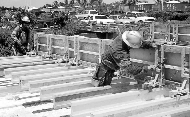
5 1 I. Product Features In combination with post shores, tripod stands, fork heads and plywood, the H20 Wood Beams provide flexible, yet cost effective formwork for any floor layout, slab thickness, and shore height. The H20 Wood Beam is lightweight at just 3.36 lbs./ft. (50 kg/m). Its high-grade beam ends assure long product life. Fig 1.1 H20 Beam A. Quick Stripping All post shores are equipped with the patented quickrelease pin. With a blow of a hammer, the bolt immediately releases the slab load on the adjusting nut. Fig. 1.2 H20 Beam End Dimensions B. Practical Accessories Accessory items make the H20 Wood Beam formwork an efficient, versatile system. For example, the tripod stand for post shores has legs that can be configured to fit along walls or corners, or even folded flat for transport. Fig. 1.3 Quick Release Pin Fig. 1.4 Tripod
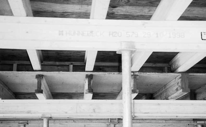
6 2 II. Deck Components A. H20 Wood Beam The 20 cm high H20 Wood Beams come in seven lengths from 9' to 21', in 2' increments. H20 Wood Beams are utilized as both joists and stringers. B. Post Shore 350 and 550 Post Shores are completely galvanized inside and out including external threads. 350: L = 6' 6'' - 11' 5'' nominal Fig. 2.1 H20 Wood Beam 550: L = 10'1'' - 18' nominal Inner tube diameter: 2.45'' nominal Outer tube diameter: 3'' nominal All shores are complete with quick-release pins. One tap with the hammer is usually enough to release the shore from its load. C. Post Shore Tripod The Post Shore Tripod is designed for steadying the 350 and 550 Post Shores during erection procedures (maximum 3'' diameter post). The Hinged design accommodates common angular patterns, such as 90, 180 and 360 degrees. It also folds flat for transport. D. Swivel Clamp The 1.9" to 3" Swivel Clamp allows attachment of additional bracing to 350 and 550 post shores. E. 2-Way Fork Head The Fork Head retains one or two beams, depending on which direction the head faces. Fig. 2.3 Post Shore Dimensions Fig. 2.4 Swivel Clamp Fig. 2.3 Tripod
7 3 F. Intermediate Support Head This head is used on individual stringers when additional support is needed between post shores with Fork Heads. G. T-Spring Bolt Secures the Fork head or Intermediate Support head to the post shore through the holes down the side of the inner tube. H. Post Shore Sleeve The post shore sleeve adapts the wider top opening of the 550 Post Shore to accommodate the Fork head and Intermediate Support heads. I. Assembly Fork Simplifies the placement and removal of H20 Wood Beams by extending worker reach. J. Product Codes and Weights Fig. 2.5 Fork Head Fig. 2.7 T-Spring Bolt Fig. 2.6 Intermediate Support Head Fig. 2.8 Post Shore Sleeve Product Code Description Weight WOOD BEAMS SW Wood Beam (H20) 39' SW Wood Beam (H20) 21' - Purple 70.7 SW Wood Beam (H20) 19' - Light Blue 63.9 SW Wood Beam (H20) 17' - Orange 57.2 SW Wood Beam (H20) 15' - Red 50.5 SW Wood Beam (H20) 13' - Green 43.7 SW Wood Beam (H20) 11' - White 37.0 SW Wood Beam (H20) 9' - Dark Blue 30.3 Fig. 2.9 Assembly Fork
8 4 III. Use and Erection for Decks System erection begins with assembling post shore components which will be placed at proper layout distances. (Important: See Maximum Allowable Stringer Beam Span table, and Post Shore Capacity table in section VI for slab support design information.) A. Attach 2-Way Fork Head to Post Shores To begin system setup, a 2-Way Fork Head must be attached to a post shore (either the 350 or the 550). If the 550 post shore is utilized, a Post Shore Sleeve is first inserted in the hole at the top of the post shore. The Fork Head is inserted, and the T-Spring Bolt is pushed into a hole in the side of the post shore to secure the head. Adjust the post shore at roughly the required dimension while it lays flat. Fig. 3.1 Attaching Fork Head to Post Shore B. Attach Tripod to Post Shores Tripods stabilize post shores during erection procedures. The post shoe is set in the open stand and secured by the clamping loop with a gentle blow of a hammer. The Tripod can be used with either post shore type. The support legs of the Tripod permit an optimal fit, even in the corners of the structure. Fig. 3.2 Tripod Attached to Post Shore After the H20 Wood Beam formwork erection is completed, the Tripod can be removed. They must remain in place at the end of each stringer beam until post shore lateral bracing has been installed and tied into the existing structure, such as columns or walls. The Tripod can be folded flat for convenient storage and easy transport. Fig. 3.3 Tripod Leg Configurations Fig. 3.4 Tripod Removal and Folded Flat
9 5 C. Place Stringer Beams Once the post shores are in place, stringer beams are placed in the Fork Heads. Assembling Forks extend worker reach to make this an easier operation. After stringer beams are in place, post shores should be adjusted for floor level to ceiling height, slab thickness, and maximum load capacity. When Intermediate Supports are required, the post shore assembly swings into place under the stringer beam and adjusted for stringer beam height. Fig. 3.5 Stringer Placement Fig. 3.6 Positioning Intermediate Supports D. Position Joist Beams and Plywood Panels Position joists with the Assembly Fork. (Refer to Table 1: Maximum Allowable Plywood Span and Table 2: Maximum Allowable Joist Span in Span Section IV for spacing information.) Joist ends must extend past stringers. Plywood panels are placed on top of the joist beams and tacked into place. A joist must be located at every plywood butt joint. Caution: Guardrails must be erected on the open edges of the structure as required by local, state, and federal regulations. Fig. 3.7 Typical Joist Configuration Fig. 3.8 Typical Plywood Application
10 6 Deck Assembly Procedures 1. Secure the 2-Way Fork Head in the top of post shores (Fig. 3.1). 2. Set up Tripod stands. 3. Secure the post shores in the Tripod stands (Fig. 3.2). 5. Place additional post shores with Intermediate Support Heads in accordance with the tables in Section IV. 6. Lay joist beams (Fig. 3.7). 7. Lay plywood panels (Fig. 3.8). 4. Lay the stringer beams in the Fork Heads (Fig. 3.5). Stringer Beam Joist Beam Fig. 4.1 Typical Floor Layout ¾" Plywood Fig. 4.2 Section of Typical Floor Layout
11 7 V. Deck Stripping Caution: Moving and lowering system components requires strict attention to worker safety. 1. Lower the post shore by tapping the Quick-Release Pin with a hammer (Fig. 1.3). This lowers the panel about ¼" to relieve the load on the post shore. Turn the Adjustment Screw on the post twice to provide additional clearance. 5. Turn the joist beams diagonally and lower through stringer beam spacing. The Assembly Fork can be used to reposition and lower the joists. 2. Use the Assembly Fork to rotate joists 90 degrees onto their sides. This increases the space between the formwork and the slab. Fig. 5.4 Turn and Lower Joists 6. Lift the stringer beams out of the Fork Heads. Fig. 5.1 Rotating Joist Beams 3. Push joist beams together, creating space to remove the plywood panels. Fig. 5.5 Lift and Lower Stringers Fig. 5.2 Moving Joist Beams Aside 4. Remove plywood panels and lower through stringer beam spacing. 7. Tripod stands and post shores can be separated for storage or transport. Fig. 5.3 Remove Plywood
12 8 VI. Tables for H20 Slab Support Design Layouts of the H20 Beam Support system can be determined using the following tables. Table 1: Maximum Allowable Plywood Span provides the center-to-center spacing of the joists and is determined by the slab thickness. Table 2: Maximum Allowable Joist Span relates joist spacing to slab thickness Table 3: Maximum Allowable Stringer Span & Post Shore Load determines the spacing of the post shores. The load on the post shore is indicated below the stringer span. Table 4: Post Shore Heights and Capacities provides a way to check the Resulting Load against the Allowable Load for the chosen post at the given application height. Table 1: Maximum Allowable Plywood Span For typical support spacing using ¾" Plyform, Class 1 plywood. Max. Allowable Joist Max. Allowable Slab Thickness (in.) Spacing Load (psf) L/360 L/270 (inches) L/360 L/ " 122.4" " 54.4" " 28.8" " 18.8" " 8.8" Notes: 1. Plywood face grain across supports. 2. Plywood is assumed continuous across 2 or more spans. 3. All Slab Thickness values include 50 psf live load. Table 2: Maximum Allowable Joist Span Concrete Deflection = L/360 Deflection = L/270 Thickness Joist Spacing: Joist Spacing: inches 8" 12" 16" 19.2" 24" 8" 12" 16" 19.2" 24" 6 11' - 0" 11' - 0" 7 12' - 0" 11' - 0" 12' - 0" 11' - 0" 8 12' - 0" 11' - 0" 10' - 0" 12' - 0" 12' - 0" 10' - 0" 9 11' - 0" 11' - 0" 10' - 0" 12' - 0" 11' - 0" 10' - 0" 10 11' - 0" 10' - 0" 10' - 0" 12' - 0" 11' - 0" 10' - 0" 11 12' - 0" 11' - 0" 10' - 0" 9' - 0" 12' - 0" 11' - 0" 10' - 0" 9' - 0" 12 11' - 0" 10' - 0" 10' - 0" 9' - 0" 12' - 0" 11' - 0" 10' - 0" 9' - 0" 13 11' - 0" 10' - 0" 9' - 0" 9' - 0" 12' - 0" 11' - 0" 10' - 0" 9' - 0" 14 11' - 0" 10' - 0" 9' - 0" 8' - 0" 12' - 0" 10' - 0" 9' - 0" 8' - 0" 15 11' - 0" 10' - 0" 9' - 0" 8' - 0" 12' - 0" 10' - 0" 9' - 0" 8' - 0" 16 12' - 0" 10' - 0" 9' - 0" 9' - 0" 8' - 0" 12' - 0" 11' - 0" 10' - 0" 9' - 0" 8' - 0" 17 12' - 0" 10' - 0" 9' - 0" 9' - 0" 8' - 0" 12' - 0" 11' - 0" 10' - 0" 9' - 0" 8' - 0" 18 11' - 0" 10' - 0" 9' - 0" 8' - 0" 8' - 0" 12' - 0" 11' - 0" 9' - 0" 8' - 0" 8' - 0" 24 10' - 0" 9' - 0" 8' - 0" 7' - 0" 7' - 0" 11' - 0" 10' - 0" 8' - 0" 7' - 0" 7' - 0" Notes: 1. Bold numbers indicate deflection exceeds >/270 for ¾" plywood deflection limits. See Table 1: Maximum Plywood Pressure. 2. Live load is not included in deflection calculations. 3. Joist table is based on a single span condition. 4. Shaded areas within the table indicate span limited by deflection.
Experience the Hi-Lite Advantage
 Experience the Hi-Lite Advantage 12K Aluminum Shoring System INTRODUCTION The 12K Shoring System is primarily a hand-set system. It can also be handled with a crane, and may also be used quite successfully
HV Support System. The HV Support System is compatable with all CSS Support Systems:
 HV Support System HV Support System The HV Support System is compatable with all CSS Support Systems: Aluminum 225 Stringer Beam Twin Beam Support System Drop Deck Support Systems Deck Panel Support System
THE POWER OF RED SPACE-LIFT CONCRETE CONSTRUCTION PRODUCTS APPLICATION GUIDE
 SPACE-LIFT THE POWER OF RED CONCRETE CONSTRUCTION PRODUCTS APPLICATION GUIDE A WORD ABOUT SAFETY High productivity depends on safety; even a minor accident causes job delays and inefficiency, which run
Figure 1. RAILING INSTALLATION The following instructions describe the installation of three types of railing sections: Line, Stair, and Angled
 Veranda Railing System Veranda railing systems are designed to work with a number of different decking materials and surfaces. Before initiating any project, obtain a copy of your local building codes
Installation Instructions for the AlphaDeck Staging System
 Installation Instructions for the AlphaDeck Staging System Step 1 - Preparation A. Before setting up your system, determine the location where the stage will be installed and locate all the parts you will
Installation Instructions for. Before You Begin TOOLS REQUIRED
 Composite Railing System STEP-BY-STEP Installation Instructions for Spectrum Composite Railing Virtually maintenance free 20-year warranty EverNew Spectrum Railing system is designed to work with a number
MEP Shoring System Technical Instruction Manual
 MEP Shoring System Technical Instruction Manual The MEP Shoring System is a versatile yet simple system capable of handling virtually any project with only two basic components: The post shore and the
SPACE-LIFT DAYTONSUPERIOR.COM APPLICATION GUIDE. Jump Forming System
 SPACE-LIFT Jump Forming System APPLICATION GUIDE The Space-Lift system is a fully-engineered jump form system intended for concrete shear wall applications. The system consists of frame components and
How to Use the Jahn Forming System
 How to Use the Jahn Forming System 1. Preparation Gang drilling the plywood is the only preparation required. Holes need to be drilled 1/8" larger than the snap tie head. Normally, a 5/8" diameter drill
PRE-ENGINEERED HORSE STALL SYSTEMS SDFD SLIDING DOOR c/w FOLD-DOWN GRILL. & Assembly. Installation Instructions
 PRE-ENGINEERED HORSE STALL SYSTEMS 4800 SDFD SLIDING DOOR c/w FOLD-DOWN GRILL & Assembly Installation Instructions 4800 SDFD Sliding Door c/w Fold-Down Grill Components - 1 3 /4" x 2" x 88" channels (2)
Meva Guided Screens MGS Technical Instruction Manual
 Meva Guided Screens MGS Technical Instruction Manual Product Characteristics: The MEVA Guided Screens (MGS) system encloses complete floors especially in high-rise construction independent of the height
Big expertise. Real convenience. Concrete commitment. stem
 1300 659 830 www.formdirect.com.au Big expertise. Real convenience. Concrete commitment. Stee l Pre-e P n g i n eere ly Fo conc d rete form, factory rmin ing s ystem built, re-u g sy sable stem Steel-Ply
PERFORM WITH PRECISION MAX A FORM STS FORMING SYSTEM CONCRETE CONSTRUCTION PRODUCTS APPLICATION GUIDE
 MAX A FORM STS FORMING SYSTEM PERFORM WITH PRECISION CONCRETE CONSTRUCTION PRODUCTS APPLICATION GUIDE A WORD ABOUT SAFETY High productivity depends on safety; even a minor accident causes job delays and
installation care & maintenance instructions lifecycledecking.com 25-year limited residential warranty 20-year limited commercial warranty
 installation care & maintenance instructions lifecycledecking.com 25-year limited residential warranty 20-year limited commercial warranty Installation Instructions As with any building project, use proper
Lok Fast Column Clamp General Information
 Lok Fast Column Clamp General Information Gates Lok-Fast Column Clamp Has These Advantages: Can Be Job Built Gang Formed No Loose Pieces Designed For Rapid Placement of Concrete Rapid Locking Action 3
Dura-Lock Roof System
 DLR-14 Dura-Lock Roof System Assembly and Installation Instructions Read the instructions before starting the job. They explain the steps required to produce a finished product that will meet factory specifications.
woodworkersjournal.com MATERIAL LIST
 MATERIAL LIST T x W x L 1 Legs (2) 1 1 2" x 3 1 2" x 36 7 16" 2 End Uprights (2) 1 1 2" x 3 1 2" x 32 1 2" 3 Stringers (4) 1 1 2" x 3 1 2" x 42" 4 Top Cladding, Long (2) 3/4" x 7 1 4" x 65 3 4" 5 Side
Installation Instructions
 Installation Instructions For Models: Model Number / Description File Name 1540 Classic Series P-Lam Toilet Partitions 1540.pdf 1 INSTALLATION INSTRUCTIONS LAMINATED PLASTIC TOILET PARTITIONS 1540 Classic
The following instructions will guide you through the installation of your new vinyl railing.
 Installation Guide St. James Vinyl T-Rail Tools Required Protective eye glasses 3/8 x 3 Concrete Anchors/Fasteners (for Tape measure concrete installations) Variable speed drill/screwdriver Philips Driver
ASSEMBLY INSTRUCTIONS
 ASSEMBLY INSTRUCTIONS PRINTED IN USA Assembly Instructions Include: P/N: LL-04-5 Step : Site Preparation Step 0: Guard Rail Installation Step : Leg Assembly Step : Stairs Step 3-8: Setting the Stage Step
INSTRUCTION SHEET. PIECE INVENTORY - MOBILE BASES Refer to the diagram for part identification.
 INSTRUCTION SHEET D2260 HEAVY-DUTY MINI-MOBILE BASE D2057 HEAVY-DUTY MOBILE BASE D2058 SUPER HEAVY-DUTY MOBILE BASE D2259 EXTENSION KIT FOR D2260/D2057 D2246 EXTENSION RAIL KIT FOR D2058 This Shop Fox
INSTALLATION INSTRUCTIONS
 INSTALLATION INSTRUCTIONS SOLID PHENOLIC TOILET PARTITIONS 1080 DuraLine Series 1180 DuraLine Series Class-A Fire Rated IMPORTANT: Review these instructions thoroughly prior to installation. FLOOR ANCHORED
CEILING-MOUNTED MONORAIL ANCHOR TRACK SYSTEM Assembly and Operation Instruction Manual
 CEILING-MOUNTED MONORAIL ANCHOR TRACK SYSTEM Assembly and Operation Instruction Manual This manual is for various mounting types and plain and trussed track profiles. ISO 9001:2008 Registered Manual 103-0075
THE POWER OF RED STEEL-PLY CONCRETE FORMING SYSTEM APPLICATION GUIDE
 THE POWER OF RED STEEL-PLY CONCRETE FORMING SYSTEM APPLICATION GUIDE Table of Contents Introduction...1 Handles...1 Components...1 Safety Eyes...1 Fillers... 2 Wedge Bolts... 2 Steel Fillers and Long
6 1/2 x 6 1/2 Wood Grain Flat Top Pergola
 / x / Wood Grain Flat Top Pergola A S S E M B LY G U I D E Models: Lakewood OPTIONAL ACCESSORY Bolt Down Bracket Kit V.-09 Ta b l e o f Co n t e n t s The PAGE Introduction & Overview.......................................................
V nyl Gazebo truct c it Assembly Instr ons
 V nyl Gazebo Vi Assembly Instr ct tr t u ru ons ct c i ti Pre-assembly Instructions A C B #1 - Site properly prepared. 4" - 6" clean stone 9 linear blocks 2" x 8" x 16" C C A A B B #1a - 12" sauna tubes,
HOW TO INSTALL HORIZONTAL ROD RAILING TREX SIGNATURE STANDARD
 HOW TO INSTALL HORIZONTAL ROD RAILING NOTES:» Adjust drill power to lowest setting that will drive screw. DO NOT OVER TORQUE 6 STAINLESS STEEL STAINLESS FASTENERS.» NEVER use impact tools on 6 Stainless
Sales & Service. JFK - Just For Kids. sasportonline.com. 135 Forestview Road 7879 Will Rogers Blvd.
 Sales & Service sasportonline.com SA Sport (Canada) SA Sport (U.S.A.) 135 Forestview Road 7879 Will Rogers Blvd. P.O. Box 40 Fort Worth, Texas Orillia, Ontario USA 76140 Canada L3V 6H9 Telephone: (705)
PUSH-PULL-PROPS. and accessories ROBUSTA-GAUKEL GMBH MOUNTING TECHNOLOGY &CO.KG
 PUSH-PULL-PROPS and accessories MOUNTING TECHNOLOGY ROBUSTA-GAUKEL GMBH &CO.KG MOUNTING TECHNOLOGY PUSH-PULL-PROPS AND ACCESSORIES INDEX General information...................... 3 Push-pull-prop Type
Assembly Instructions 10 X 10 Aluminum Roof Support
 Assembly Instructions 10 X 10 Aluminum Roof Support Aluminum Roof Support Bolt Package 16-5/16 X 2 ¼ SS Bolt 24-5/16 X 1 SS Bolt 40-5/16 SS Nylon Lock Nuts 16-5/16 SS Flat Washers 28-4 ½ Wood Screws 36-1
6 1/2 x 6 1/2 Wood Grain Flat Top Pergola
 / x / Wood Grain Flat Top Pergola A S S E M B LY G U I D E Models: Lakewood OPTIONAL ACCESSORY Bolt Down Bracket Kit V.- Ta b l e o f Co n t e n t s The PAGE Introduction & Overview.......................................................
southpaw enterprises, inc.
 southpaw enterprises, inc. Store these instructions with the enclosed maintenance checklist in a safe place. You may also access them on our website. Instruction Sheet Prefab Joist 3 Ft. Drop Ceiling Kit
Independent Containment System (ICS)
") Installing the Independent Containment System (ICS) Complete these instructions to install the Independent Containment System (ICS). Prerequisites This installation requires a team of at least two people.
Installing the Independent Containment System (ICS) Complete these instructions to install the Independent Containment System (ICS). Prerequisites This installation requires a team of at least two people.
Sit Down Table Assembly Instructions
 Sit Down Table Assembly Instructions Parts that come with your sit down table A B C D E F G H I J K L M N Extension leaf Table with cutout for machine Two table legs One table leg with long support One
Installation Instructions
 Column & Beam Units with Debris Netting Installation Instructions Laminated Wood Systems, Inc. Seward, Nebraska 800-949-3526 2015 LWS, INC. AVR-NET INSTALL 05-12-16 AVR Installation Notes 1 Safety The
INSTALLATION INSTRUCTIONS
 INSTALLATION INSTRUCTIONS HIGH PRESSUE LAMINATE (HPL) TOILET PARTITIONS 1030 TrimLineSeries 1040 DesignerSeries Includes continuous hardware option.65. IMPORTANT: Storage and Handling Information on last
400A 40113V, 401A 40120V, & 401AL 40120VL ALUMINUM VERTICAL 4000 LB LIFT INCLUDES SCREW LEG ASSEMBLY INSTRUCTIONS
 12/11/07 PAGE 1 OF 12 400A 40113V, 401A 40120V, & 401AL 40120VL ALUMINUM VERTICAL 4000 LB LIFT INCLUDES SCREW LEG ASSEMBLY INSTRUCTIONS Thank you for purchasing our product! *Please read these instructions
Operating, Servicing, and Safety Manual Model # & 72 Ultimate Box & Pan Brake
 Operating, Servicing, and Safety Manual Model # 2800 48 & 72 Ultimate Box & Pan Brake CAUTION: Read and Understand These Operating, Servicing, and Safety Instructions, Before Using This Machine. 1-800-467-2464
Multi-Stage ASSEMBLY INSTRUCTIONS ST-8100 SERIES. 125 TAYLOR PARKWAY ARCHBOLD, OH PHONE: (419) FAX: (419)
 FAX: (419)") 125 TAYLOR PARKWAY ARCHBOLD, OH 43502 PHONE: (419) 445-8915 FAX: (419) 445-0367 www.biljax.com Multi-Stage ST-8100 SERIES ASSEMBLY INSTRUCTIONS ALL DRAWINGS ARE FOR ILLUSTRATION ONLY. PRINTED IN U.S.A.
125 TAYLOR PARKWAY ARCHBOLD, OH 43502 PHONE: (419) 445-8915 FAX: (419) 445-0367 www.biljax.com Multi-Stage ST-8100 SERIES ASSEMBLY INSTRUCTIONS ALL DRAWINGS ARE FOR ILLUSTRATION ONLY. PRINTED IN U.S.A.
Spring Loaded All Season Roll-Up Doors
 Spring Loaded All Season Roll-Up Doors STAND-OFF MOUNTING METHOD INSTALLATION INSTRUCTIONS READ THIS FIRST Carefully examine the crate(s) for damage before opening. If the carton is damaged, immediately
City of Manteca Boarding Requirements
 City of Manteca Boarding Requirements There should be no boarding above the first floor unless entry is possible without use of a ladder, and the opening is large enough for a person to easily pass through.
BEST PRACTICE GUIDE. Socket Bases. Working with Concrete Slabs
 Working with Concrete Slabs When working with concrete slabs the barrier protection can be erected in three ways - with socket bases, adjustable slab edge brackets and multi slab clamps. Socket Bases 1
The Festival Assembly Instructions
 The Festival Assembly Instructions Toll Free: 866.768.8465 Hours: 9-5 Monday-Friday EST www.homeplacestructures.com Package ships as shown CONTACT INFORMATION: HomePlace Structures 301 Commerce Drive New
INSTALLATION INSTRUCTIONS
 INSTALLATION INSTRUCTIONS SOLID PHENOLIC TOILET PARTITIONS 1080 DuraLineSeries Class-A Fire Rated Includes Institutional Hardware Option.67 IMPORTANT: Storage and Handling Information on last page. Review
General Guidelines:
 ASSEMBLY INSTRUCTIONS Congratulations on your new Patriot Dock purchase. This manual contains instructions to assemble basic dock configurations for use at typical residential shoreline application. Please
6 1/2 x 6 1/2 Wood Grain Flat Top Pergola
 6 / x 6 / Wood Grain Flat Top Pergola A S S E M B LY G U I D E Models: Lakewood OPTIONAL ACCESSORY Bolt Down Bracket Kit Ver /AUG/0 Ta b l e o f Co n t e n t s PAGE The 6.5 x 6.5 Wo o d Grain Flat Top
INSTALLATION INSTRUCTIONS
 INSTALLATION INSTRUCTIONS LAMINATED P LASTIC TOILET PArTITIONS 1540 ClassicSeries with Options IMPORTANT: Storage and Handling Information on last page. For faster, easier installation, please review these
Clopay Models 835/837 Sliding Door System Installation Guide
 Clopay Models 835/837 Sliding Door System Installation Guide The aim of this instruction is to guide you through the process of construction and fitting of Sliding Doors. Due to the number of sizes available
Installation Instructions
 Supafold Slide Aside System Three Fold Room Divider Installation Instructions Distinctive Doors Ltd Supafold Slide Aside Internal Folding System IMPORTANT: Before proceeding with the installation, and
System 3000 specifications
 System 3000 specifications Scope: Materials: Type of Bookstack: This specification covers delivery and installation of steel library shelving of the bracket type. Height, depth and accessories shall be
Installation Instructions for Vista Air Vertically Folding Walls
 Installation Instructions for Vista Air Vertically Folding Walls Use these instructions in conjunction with your shop drawings to see the specifics that are particular to the model you are installing.
GrowSpan Series 500 Door Kits
 GrowSpan Series 500 Door Kits Double Swinging Door Finished Grade Finished Grade Diagram shows a double-swinging door centered and installed in an end wall frame. The door kit includes materials for the
CONTENTS TOOL LIST U P S I D E I N N O V A T I O N S, L L C RAMP AND STEP SYSTEM ASSEMBLY INSTRUCTIONS. Revised: June 2013
 U P S I D E I N N O V A T I O N S, L L C RAMP AND STEP SYSTEM ASSEMBLY INSTRUCTIONS TOOL LIST Required Tools: - Reciprocating Saw with Metal Cutting Blade - Drill - 7/16 Drill Bit for Metal Drilling -
MPA-9000 Universal Ceiling Projector Mount Kit
 I N S T R U C T I O N M A N U A L Universal Ceiling Projector Mount Kit The Universal Ceiling Projector Mount provides a unique, simplified method of ceiling mounting your inverted projector. This low
TOLL FREE:(888) FAX:(941) ASSEMBLY of ProTEC CONCRETE STRUCTURAL INSULATED PANEL
 FAX:(941) ASSEMBLY of ProTEC CONCRETE STRUCTURAL INSULATED PANEL") ASSEMBLY of ProTEC CONCRETE STRUCTURAL INSULATED PANEL The ProTEC panels are manufactured with grooves on all four sides to accept the steel components. This grooving applies to the regular panel whose
ASSEMBLY of ProTEC CONCRETE STRUCTURAL INSULATED PANEL The ProTEC panels are manufactured with grooves on all four sides to accept the steel components. This grooving applies to the regular panel whose
6 1/2 x 6 1/2 Flat Top Pergola
 6 / x 6 / Flat Top Pergola A S S E M B L Y G U I D E Models: Portland, Liberty O P T I O N A L A C C E S S O R Y Bolt Down Bracket Kit V.-0506 Ta b l e o f Co n t e n t s PAGE The Introduction & Overview......................................................
200A FLB VERTICAL 22113V LIFT W/CHAIN DRIVE WINCH
 PG. 1 OF 11 PORTA-DOCK, INC. 200A FLB VERTICAL 22113V LIFT W/CHAIN DRIVE WINCH STEP 1. Separate and group like parts and fasteners together. Locate the winch side member with the longer upright tube and
Assembly Instructions 10 X 10 Aluminum Frame Building
 Assembly Instructions 10 X 10 Aluminum Frame Building 27 97 9 8 47 36 74 52 10 10 X 10 Square Building W/ Dome Includes: The Steel Entry Door with a Dead Bolt Lock assembly and Aluminum Door Frame. Metal
Motorcycle Lift Assembly Instructions
 Motorcycle Lift Assembly Instructions Copyright JCS 2009 Rev1M Page 1 Lift Table Assembly Instructions The following pages will assist you in the construction of your Motorcycle Lift Table. You will find
Aluminum Railing Installation. Glass Railing Spindle Railings Intimacy Railings and Panels
 Aluminum Railing Installation Glass Railing Spindle Railings Intimacy Railings and Panels This information in this manual will help you to Better understand our product line. Give you guidelines for an
ASSEMBLY AND CARE INSTRUCTIONS JUST FOR KIDS 355
 ASSEMBLY AND CARE INSTRUCTIONS VERSION: 8920100 (Revised 06/16) JUST FOR KIDS 355 SALES AND SERVICE spiethamerica.com Canada and International 135 Forestview Road, PO Box 40 Orillia, Ontario, Canada L3V
MK52 Series ULTRA-LOW FREQUENCY VIBRATION ISOLATION WORKSTATION ASSEMBLY AND OPERATION INSTRUCTIONS
 MK52 Series ULTRA-LOW FREQUENCY VIBRATION ISOLATION WORKSTATION ASSEMBLY AND OPERATION INSTRUCTIONS i Information contained in this document is subject to change without notice and does not represent a
A WORD ABOUT BRACING PART A - BUILDING A STRAIGHT, PILE BENT, OPEN DECK TRESTLE. Built in Place, Straight
 BUILDING LARGE SCALE TRESTLES You have many options when building a large scale trestle. The choices you make may be based on the prototype you are modeling; the era or industry you are modeling; or, simply
CAUTION: Before opening the crate place it flat on its side (not up right as show in the photo) Hardware included for assembling your gazebo:
 Hardware included for assembling your gazebo:") Octagon Wood Gazebo Kit Contents Hardware included for assembling your gazebo: 5/16" Lag Bolts Use to fasten post to floor 2 1/2" screws Use to fasten joist together fasten posts to outside joist fasten
Octagon Wood Gazebo Kit Contents Hardware included for assembling your gazebo: 5/16" Lag Bolts Use to fasten post to floor 2 1/2" screws Use to fasten joist together fasten posts to outside joist fasten
TREX POST MOUNT DECKING AND CONCRETE
 TREX POST MOUNT DECKING AND CONCRETE for Pressure-treated Wood Framing LOCATION AND INSTALLATION OF POST MOUNTS IMPORTANT NOTES:» EACH POST MUST BE ATTACHED AS SHOWN TO ENSURE A CODE COMPLIANT AND SAFE
Vinyl Gazebo Instructions
 P a g e 1 Vinyl Gazebo Instructions 10 Vinyl Gazebo Shown Thank you for the purchase of your New Gazebo. Depending on the size of your Gazebo, installation can usually be completed in 1 to 2 days. These
MevaDec. Contents. Ref. No. Description / Application Product m² list kg
 Ref. No. Description / Application Product m² list kg This product list includes all parts necessary for most applications. For parts required for special applications, please refer to the MEVA price list.
southpaw enterprises, inc.
 southpaw enterprises, inc. Store these instructions with the enclosed maintenance checklist in a safe place. You may also access them on our website. Instruction Sheet Wood Joist 2-1/2 Ft. Drop Ceiling
Call (770) STEP 6: Caulk bolt hole within the bracket for protection from the elements.
 STEP 6: Caulk bolt hole within the bracket for protection from the elements.") Call (770) 777 7007 Structural Deck Support System: Product Numbers: H1-GQ, H2-GCL (Also applies to H1-GK and H2-GCR) STEP 1: Following the spacing guidelines per the deck design and joist layout, mark
Call (770) 777 7007 Structural Deck Support System: Product Numbers: H1-GQ, H2-GCL (Also applies to H1-GK and H2-GCR) STEP 1: Following the spacing guidelines per the deck design and joist layout, mark
installation care & maintenance instructions moistureshield.com limited lifetime warranty
 installation care & maintenance instructions 866.729.2378 moistureshield.com limited lifetime warranty It s comforting to know that you re about to build a deck that gives you every possible advantage.
Gared Pro-S Portable Backstop
 Models: 9616 & 9618 Installation, Operation and Maintenance Instructions Please read all instructions before attempting installation or operation of these units SAVE THESE INSTRUCTIONS FOR FUTURE USE PUBLICATION
Ultra Space Saver American Bicycle Security Company
 The Ultra Space Saver is userfriendly and allows easy access to bikes. It provides convenient space for u-lock security on nearly any bike, including bikes with fenders and fork shocks. The double-sided
Qwik-Fence Installation Instructions
 Qwik-Fence Installation Instructions 1 Tools Required The following installation instructions should be used as a guide for installing Folding Guard Qwik-Fence Partitions. Good common sense and appropriate
Chapter 23. Garage Construction
 Chapter 23. Garage Construction 23.1 ESTABLISHING CHALK LINES 23.2 MEASURING AND CUTTING WALL PLATES 23.3 MARKING WINDOW & DOOR LOCATIONS ON EXTERIOR WALL PLATES 23.4 MARKING STUDS ON EXTERIOR WALL PLATES
Lenox Slide Lock Pergola
 ASSEMBLY GUIDE Models: Lenox OPTIONAL ACCESSORIES Bolt Down Bracket Kit ( for Pergola) Ver.0-076 Table of Co n t e n t s Introduction & Overview...................................................... Pergola
Assembly Instructions & General Overview
 Assembly Instructions & General Overview 1. General Overview & Assembly Order...Page 3 2. Assembling the Structural Components Page 4-11 3. Power, Data, Power Poles and Cable Floor Boxes.Page 12-17 4.
SCHACHT STANDARD FLOOR LOOMTM
 SCHACHT STANDARD FLOOR LOOMTM FL3109 FL3111 FL3113 FL3115 FL3121 FL3123 FL3125 FL3127 FL3310 FL3312 FL3314 FL3316 FL3322 FL3324 FL3326 FL3328 Assembly instructions LOW CASTLE LOOM IN MAPLE Find out more
HOW TO INSTALL HORIZONTAL ROD RAILING TREX SIGNATURE STANDARD
 HOW TO INSTALL HORIZONTAL ROD RAILING NOTES:» Adjust drill power to lowest setting that will drive screw. DO NOT OVER TORQUE 36 STAINLESS STEEL STAINLESS FASTENERS.» NEVER use impact tools on 36 Stainless
Spiral Slide
 IMPORTANT Page 1 PLEASE READ THESE INSTRUCTIONS BEFORE COMMENCING ASSEMBLY. All equipment must be installed in accordance with these instructions. Check your shipment against Bill of Lading and Parts list.
IMPORTANT: installation. FLOOR ANCHORED CEILING HUNG OVERHEAD BRACED FLOOR-TO- CEILING ANCHORED
 INSTALLATION INSTRUCTIONS MAXIMUM PRIVACY COMPACT LAMINATE TOILET PARTITIONS 2080 DuraLineSeries 2180 DuraLineSeries Class-A Fire Rated Includes Institutional Hardware Option.67 IMPORTANT: Storage and
10x10 Trellis Pergola
 0x0 Trellis Pergola ASSEMBLY GUIDE Ver.0-7 Table of Contents PAGE Introduction & Overview...................................................... Pergola Materials Overview..............................................................
OPERATION, PARTS & MAINTENANCE MANUAL MODELS HB73-16 HB97-18 HB97-16 HB97-12 HB HB HB HB145-18
 OPERATION, PARTS & MAINTENANCE MANUAL MODELS HB73-16 HB97-18 HB97-16 HB97-12 HB121-18 HB121-16 HB121-14 HB145-18 Proudly Made in the USA 2 3 4 FOREWORD This manual has been prepared for the owner and operators
The following instructions will guide you through the installation of your new vinyl railing stair kit.
 Installation Guide Vinyl Standard Stair Railing Tools Required Protective eye glasses Tape measure Variable speed drill/screwdriver Rotary hammer or hammer drill and masonry percussion bit recommended
12 x 24 Flat Top Pergola
 A S S E M B LY G U I D E OPTIONAL ACCESSORIES: Bolt Down Bracket Kit Privacy Wall (6 for Pergola) Pergola Planter Ver.-75 Ta b l e o f Co n t e n t s PAGE Introduction & Overview......................................................
OPERATION, SERVICE AND PARTS INSTRUCTION MANUAL 1813 BENDING TABLE FOR 881 HYDRAULIC BENDER
 OPERATION, SERVICE AND PARTS INSTRUCTION MANUAL 1813 BENDING TABLE FOR 881 HYDRAULIC BENDER Read and understand this material before operating or servicing this bender. Failure to understand how to safely
IMPORTANT -- SPECIAL INSTALLATION INSTRUCTIONS
 IMPORTANT -- SPECIAL INSTALLATION INSTRUCTIONS ** READ ALL INSTALLATION INSTRUCTIONS BEFORE STARTING!** If at any point, you have questions, call 1-800-851-0865...(The manufacturer will not be responsible
PRE-ENGINEERED HORSE STALL SYSTEMS 4884 HSD STANDARD SLIDING DOOR. & Assembly. Installation Instructions
 PRE-ENGINEERED HORSE STALL SYSTEMS 4884 HSD STANDARD SLIDING DOOR & Assembly Installation Instructions 4884 HSD Standard Sliding Door Components Some Considerations When Choosing Your Stall System - 1
Installation Guide. Capped Cellular PVC Fencing. Table of Contents. Storage and Handling Tools Needed Fence Layout and Locating Posts
 Capped Cellular PVC Fencing Installation Guide Table of Contents Storage and Handling Tools Needed Fence Layout and Locating Posts Installation instructions 4 x 4 Over Sleeve Post - 3.5 Rail Privacy Shadowbox
KIT ASSEMBLY INSTRUCTIONS
 KIT ASSEMBLY INSTRUCTIONS We have designed these instructions as a stepby step procedure to simplify the assembly process. Nevertheless, we do recommend including someone with carpentry expertise on your
Installation Manual. Solid Plastic Toilet Partitions. IN CANADA & AREAS OTHER THAN U.S.A.: IN THE U.S.A.:
 Installation Manual Solid Plastic Toilet Partitions Toilet Partitions & Lockers IN THE U.S.A.: Hadrian Inc., 7420 Clover Avenue, Mentor, OH 44060 Telephone: 440-942-9118 Fax: 440-942-9618 U.S. toll free
CertainTeed INSTALLATION GUIDE SIMTEK FENCE PRODUCTS. Fence Installation Guide 3', 4' & 6' High
 CertainTeed INSTALLATION GUIDE SIMTEK FENCE PRODUCTS Fence Installation Guide 3', 4' & 6' High INSTALLATION GUIDE These instructions are designed to assist both professional installers and do-it-yourselfers
8 x 8 Flat Top Pergola
 A S S E M B L Y G U I D E O P T I O N A L A C C E S S O R Y Bolt Down Bracket Kit Models: Mirage, Mandalay Ver 6/00 Ta b l e o f Co n t e n t s Introduction & Overview......................................................
PAINT & MISC. Notes. Table of Contents. Front Handrail Posts Front Handrails Closet Shelving Exterior Deck...
 118 PAINT & MISC. Table of Contents Front Handrail Posts... 119 Front Handrails... 122 Closet Shelving... 125 Exterior Deck... 127 Look for painter s tape on the hammer drill for where to set the depth.
MM340 Installation Instructions IMPORTANT SAFETY INSTRUCTIONS - SAVE THESE INSTRUCTIONS
 MM30 Installation Instructions IMPORTANT SAFETY INSTRUCTIONS - SAVE THESE INSTRUCTIONS Please read this entire manual before you begin. Do not unpack any contents until you verify all requirements on PAGE.
13MM FLAT WRENCH FOR LEVELING THE GLIDES OF STRUCTURE 6MM ALLEN KEY FOR ROOF CLIPS PHILLIPS HEAD BIT FOR SCREWS FOR DOOR FRAME
 1 TOOLS REQUIRED: MOVING CART/DOLLY FOR TRANSPORTING PANELS, ROOF, AND POSTS TWO 9 FT. STEP LADDERS FOR INSTALLING ROOF & PANELS REVERSIBLE RATCHET 1/4 DRIVE FOR CORNER SCREWS ON TOP TRAVERSE BEAMS ALTERNATIVE
12 x 12 Flat Top Pergola
 x Flat Top Pergola Model: Regency, Roosevelt A S S E M B L Y G U I D E O P T I O N A L A C C E S S O R Y Bolt Down Bracket Kit ( for Pergola) Ver./MAR 0 Ta b l e o f Co n t e n t s PAGE x Flat Top Pergola
Fixed Wall Arm. Installation Guide. Part number Rev E 2012 PolyVision Corporation All rights reserved
 Fixed Wall Arm Installation Guide Part number 2002003-001 Rev E 2012 PolyVision Corporation All rights reserved Table of contents Important Safety Instructions... 3 Overview... 4 Important considerations...
VARIABLE TERRAIN STAGE AND RISER SYSTEM
 VARIABLE TERRAIN STAGE AND RISER SYSTEM BEFORE YOU BEGIN... Read and understand these instructions before operating. Use caution and care for your back when lifting, pushing, pulling, or folding and unfolding
Outdoor Water Solutions, Inc. Small Backyard Windmill. Installation Manual
 Outdoor Water Solutions, Inc. Small Backyard Windmill Installation Manual Customer Service: 1-866-471-1614 Website: www.outdoorwatersolutions.com Springdale, Arkansas 72764 Phone: 1-866-471-1614 Fax: 1-479-750-9178
TREX REVEAL RAILING Installation Instructions
 TREX REVEAL RAILING NoteS:» Reveal railings are designed to be attached with posts installed at a clear span of 6' (.8 m) or 8' (.44 m).» If installing at exact span lengths of 6' (.8 m) or 8' (.44 m),