How to build a Ram for Challenge E: Twist-O-Rama
|
|
|
- Della Phebe Hunt
- 5 years ago
- Views:
Transcription

1 How to build a Ram for Challenge E: Twist-O-Rama
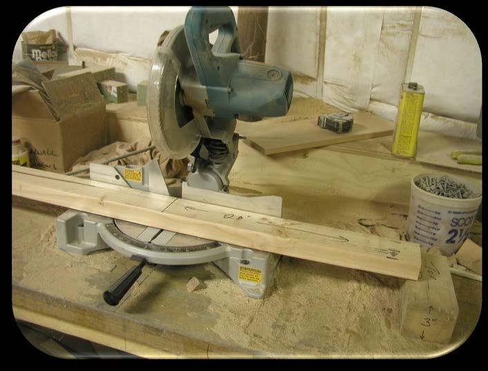
2 Notes The Ram is like the Structure Tester it is not Interference for a Team Manager or other non-team members to build it. Construction time is approximately 2 hours using a power miter saw and a power drill/driver.
 for RAM Head 20in (51cm) for Ram base 20in (51cm) for Ram base upright 12in (31cm) for Ram base extension 3½in (9cm) for Ram base foot Quantity 2 1 1 2 3 3 2 13in (33cm) of 2in x 6in")
3 Bill of Materials Item BOM Description 8ft of 2in x 4in (5cm x 10cm) dimensional lumber (Select or Premium grade) 1 1.a 1.b 1.c 1.d 1.e 24in (61cm) for RAM Head 20in (51cm) for Ram base 20in (51cm) for Ram base upright 12in (31cm) for Ram base extension 3½in (9cm) for Ram base foot Quantity in (33cm) of 2in x 6in (5cm x 15cm) dimensional lumber (Select or Premium grade) in (7.6cm) Wood screws 2½in (6cm) Wood screws #8 X 2in (6cm) round-head wood screws #8 X 1½in (3.8cm) in round-head wood screws #8 or #10 fender washers /8in (.32cm) X ¾in (2cm) X 48in (122cm) flat aluminum bar 1 6in (15cm) for the Parallel bar 41/8in (10.5cm) for the Ram Stop 1in (2.5cm) cup hooks mouse pad a 8.b 9 10

4 Tools Required Saw Handsaw, Table saw, Power miter saw (all can do the job, but the power miter saw is preferable)

5 Tools Required Hacksaw for cutting aluminum bar
, 1/8in (.")
, and 3/16in (1.")
6 Tools Required Drill with 1/16in (.625cm), 1/8in (.32cm), 11/64in (1.72cm), and 3/16in (1.87cm) bits.

7 Tools Required Screwdrivers (screwdriver bits strongly recommended)

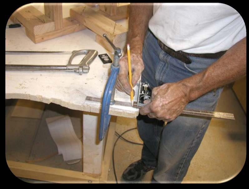
8 Tools Required Tape measure and pencil

9 Tools Required Square with a 12in (30.5cm) or longer straightedge

10 Tools Required 2 clamps not necessary, but helpful
11 Tools Required Wood Glue Rubber mouse pad
12 Select and Cut Lumber The 2in x 4in (5cm x 10cm) and 2in x 6in (5cm x 15cm) boards need to be straight and free of twists. Taking an extra minute or two to carefully select them will save you a lot of time and effort later. If lumber yard or home center provides a cutting service and you are uncomfortable with power saws, get them to do the cutting for you. It is best to cut the longest length first, then the next longest, and so on. If there is a mistake, there will be enough remaining length for a second chance.
 for the Ram base support 1 piece 20in (51cm) for the Ram base uprights 2")
13 Select and Cut Lumber Cut the 2in x 4in (5cm x 10cm) lumber into the following lengths: 24in (61cm) for the Ram Head 1 piece 20in (51cm) for the Ram base support 1 piece 20in (51cm) for the Ram base uprights 2 pieces

14 Select and Cut Lumber
 for the Ram base support 1 piece 20in (51cm) for the Ram base uprights 2")
15 Select and Cut Lumber Cut the 2in x 4in (5cm x 10cm) lumber into the following lengths: 20in (51cm) for the Ram base support 1 piece 20in (51cm) for the Ram base uprights 2 pieces
16 Select and Cut Lumber For actual length Each Ram must be custom fit to each Tester Base Measure the height of the Tester Base from floor Add 16-5/8in (42.23cm) to the Tester Base height Subtract this number from 21½in (54.6cm) Remove this amount from each 20in (51cm) upright For example if the Tester Base = 3½in (8.9cm) the formula would be [21½in (54.6cm) (3½in (9cm) /8in (42.23cm) ) = 1-3/8in (3.5cm)]

17 Select and Cut Lumber Cut the 2in x 4in (5cm x 10cm) lumber into the following lengths: 12in (30.5cm) for the Ram base extensions 3 pieces
 for the Ram base feet 3 pieces")
18 Select and Cut Lumber Cut the 2in x 4in (5cm x 10cm) lumber into the following lengths: 4in (10cm) for the Ram base feet 3 pieces
 for the Ram base top support")
19 Select and Cut Lumber Cut the 2in x 6in (5cm x 15cm) lumber into the following lengths: 13in (33cm) for the Ram base top support member

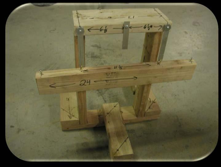
20 Base Assembly On the 20in (51cm) base piece, mark 5in (13cm) in from each end. Use a square to extend the mark across the wood.
21 Base Assembly Place the Ram head in a separate location from the others so it will not be accidentally used for another purpose.
22 Base Assembly Align one end of each upright with the base on the outside edge of the line.
 pilot holes about 2 1/4in (5.")
23 Base Assembly Drill 2-3/16in (1.87cm) pilot holes about 2 1/4in (5.7cm) deep through the Ram base and into the end of each upright.
 screws into the holes to secure the upright")
24 Base Assembly Secure with 3in (7.6cm) screws into the holes to secure the upright to the Ram base.
25 Base Assembly The distance between the inner faces of the uprights should be exactly 10in (25.4cm).
26 Base Assembly Place 2in x 6in (5cm x 15cm) Ram base top support member onto the top of the uprights so that the edge of the 2in x 6in (5cm x 15cm) is aligned with edge of 2in x 4in (5cm x 10cm) uprights.
27 Base Assembly Drill 2-3/16in (1.87cm) pilot holes 2¼in (5.7cm) deep through the Ram base top support and into the end of each upright.
 screws into the holes to secure the upright to")
28 Base Assembly Secure with 3in (7.6cm) screws into the holes to secure the upright to the Ram base top support.
")
29 Base Assembly Align 2-12in (31cm) Ram base extensions at the ends of the Ram base so the extensions extend in the opposite direction of 2in x 6in (5cm x 15cm) overhang.

 wood screws for each")
30 Base Assembly Secure the Ram base extensions to the Ram base with 2 2½in (6.4cm) wood screws for each upright piece.

31 Base Assembly


32 Base Assembly Align the remaining 12in (31cm) Ram base extension in the center of the Ram base between the uprights facing the opposite direction of the previous Ram base extensions. Secure with 2 2½in (6.4cm) wood screws.

33 Base Assembly Secure the Ram s feet to the upright pieces with 2 2½in (6.4cm) wood screws each.


34 Base Assembly Cut the mouse pad to fit each foot and at each end of Ram Base. Secure the pads to the undersides of the feet and the Ram base ends with wood glue. This should provide protection for floor surfaces.

35 Aluminum Parallel Bars Using a hacksaw, cut 2 pieces of bar 6in (15.25cm) in length.

36 Aluminum Parallel Bars

37 Aluminum Parallel Bars Tape the 2 pieces together flush.
 drill bit, drill holes 3/8in (1cm) from each end,")
38 Aluminum Parallel Bars Using an 11/64in (1.72cm) drill bit, drill holes 3/8in (1cm) from each end, centered between the edges.
 in from the outside edge and centered top and bottom. The holes should be roughly 1in (2.")
39 Aluminum Parallel Bars Using a 1/8in (.32cm) drill bit, drill 2 holes in the overhanging edge of the Ram base top support. The holes should be ¾in (2cm) in from the outside edge and centered top and bottom. The holes should be roughly 1in (2.5cm) deep.


 Add another")
40 Aluminum Parallel Bars 1 On each of the #8 round-head wood screws, place: A fender washer 2 One of the parallel aluminum arms (from the first step) Add another washer to space 3

41 Aluminum Parallel Bars Drive the screws with their parallel arms into the upright pieces until the arms are snug, then back the screws out ¼ turn each.

42 Aluminum Parallel Bars

43 Hang the Ram Head Measure the distance between the roundhead screws driven into the Ram base top support. The distance is center-to-center. (Tip: Left edge to left edge, or right edge to right edge produces the same result if your eye can t find the center.)

44 Hang the Ram Head Subtract this distance from 24 inches (61cm). Divide the result by 2. Mark the top edge of your Ram head this distance in from each end. Find the center between the edges.
45 Hang the Ram Head Using a 1/16in (.625cm) drill bit, drill shallow starter holes for the cup hooks.


46 Hang the Ram Head Screw the cup hooks into the holes, lining them up so the hooks are across the Ram head, in opposite directions.

47 Hang the Ram Head
 screw in line with the cup hook holes,")
 of screw exposed.")
48 Hang the Ram Head Drive a #8 x1½in (3.8cm) screw in line with the cup hook holes, one inch from each end, leaving ¾ in (1.9cm) of screw exposed. These are the pull and release handles.

49 Hang the Ram Head

50 Hang the Ram Head Hang the Ram head from each of the parallel arms. On a level floor, the Ram head should now also be level. Small adjustments are possible in the cup hooks themselves.
51 Ram Stop The amount of Ram head drop, and thus the amount of energy delivered, has been set at 3in (7.6cm).
52 Ram Stop Measure on the remaining piece of aluminum bar 4 1/8in (10.48cm) from one end. Using a hacksaw, cut the Ram Stop from the aluminum bar.
 hole ¾in (1.")
53 Ram Stop Drill a 11/64in (1.72cm) hole ¾in (1.9cm) from one end of the Ram Stop.
 from the end and mark it.")
54 Ram Stop On the Ram base top support measure 6½in (16.5cm) from the end and mark it. Draw a line vertically on this mark.
 above the top of the Ram. Mark where the hole in the Ram Stop is along the vertical line.")
55 Ram Stop With the Ram head at rest, align the Ram Stop so that the edge without the hole is 3in (7.6) above the top of the Ram. Mark where the hole in the Ram Stop is along the vertical line.
 hole into the Ram base top")
56 Ram Stop Drill a 1/8in (.32cm) hole into the Ram base top support.

57 Ram Stop Secure the Ram Stop to the Ram base top support with the remaining #8 round-head wood screw.

58 Completed Ram
136 PLYWOOD DESK 522
 136 PLYWOOD DESK 522 Simple in design and inexpensive, this plywood desk is made from a single 4- x 8-foot panel. Plywood is available with many hardwood veneers; it can also be covered with plastic laminate,
CONTINUED. TABLE TOPS: 1. Sort one 2x6x8 piece from your lumber. 2. Measure and mark two 48 pieces from each, then cut.
 # Materials: Quantity Each: Total Quantity: x4x8 7 x6x8 1 TIPS FOR SUCCESSFUL PREP WORK: Before starting, carefully read through the entire instruction sheet. Refer to the material list to the left and
Desk/Wall-Mount Rack
 Desk/Wall-Mount Rack Patent(s) Pending Installation Instructions Post P/N: 119-1752 119-1781 119-1782 119-4014 Frame P/N: 119-1591 119-1754 119-1755 Kit Contents (2) Frames (4) Posts Assembly Hardware
How to fit an Internal Door
 How to fit an Internal Door How to fit an Internal Door The following instructions are for installing a internal door only. If you have any queries please contact Cheshire Mouldings technical helpline
Making Simple Bookbinding Equipment
 Tony Firman 20 1 2 19 Notes Tony Firman Tony Firman Bookbinding 18 3 : 2012 Tony Firman Bookbinding P.O. Box 507 Haslet, TX 76052 www.tonyfirmanbookbinding.com 4. When all the tapes have been pinned in
WALL MOUNT LOCKER ASSEMBLY. 208 Chestnut St, Reading, PA (610)
") WALL MOUNT LOCKER ASSEMBLY 208 Chestnut St, Reading, PA 19602 (610)376-2666 Locker Assembly Wall Mount: locker Installation Introduction: Before beginning, check to ensure the floor is level, and the wall
WALL MOUNT LOCKER ASSEMBLY 208 Chestnut St, Reading, PA 19602 (610)376-2666 Locker Assembly Wall Mount: locker Installation Introduction: Before beginning, check to ensure the floor is level, and the wall
McCue Bumper Installation Instructions
 McCue Bumper Installation Instructions McCue 8" Bumper Tools Required: Saw with 10-12" blade Tape measure Flat head screwdriver Phillips screw driver Pencil or chalk line Drill with Philips driver bit
Contest Field Border Construction Manual
 Contest Field Border Construction Manual TABLE OF CONTENTS Section 1 Field Construction...3 Section 2 Bill of Materials 3 Section 3 Construction.. 4 Step 1 - Layout...4 Step 2 - Bottom...4 Step 3 1 st
Top Mount Ultra Modern Hanger
 Top Mount Ultra Modern Hanger ASSEMBLY INSTRUCTIONS TOP MOUNT ULTRA MODERN HANGER Recommended Tools Level Tape Measure Pencil Drill with 1/8, and 1/4, Drill Bits and Phillips Bit Socket Wrench with 9/16
PLANS BY TOM BURY MURPHY WORKTABLE TOTAL DIMENSIONS: FOLDED UP 30 X 48 X 0 FOLDED DOWN 30 X 58 X 84
 MURPHY WORKTABLE TOTAL DIMENSIONS: FOLDED UP 30 X 48 X 0 FOLDED DOWN 30 X 58 X 84 MATERIALS LIST: (2) 2 x8 x8 (3) 2 x4 x8 (1) 1 x2 x8 (1) 48 x96 3/4 plywood (2) 1-1/2 x30 continuous hinge (1) Left-side
ROCKWELL. Two Panel Door. Half X Door. Double X Door. Z Combination Door
 ROCKWELL 4 in 1 DOOR Choose between four door styles with this Door Kit. Our versatile Rockwell Door Kit is very easy to assemble. All materials and hardware needed to assemble any of the four styles are
Close Encounters of the Bird Kind
 Close Encounters of the Bird Kind Building some bird housing will improve your libido as the natural forces of Spring work their magic. Materials: ¾", 2" and 3" exterior screws 1" x 8" pine or spruce 1"
Patio Table. Page 1 of 16
 Patio Table www.andrewharriswoodwork.com Page 1 of 16 Introduction This plan makes a table that is unit which is 95 ½ inches long and 49 inches wide. The distance from the underside of the top edging to
Low/High Tunnel Greenhouse Plans
 Low/High Tunnel Greenhouse Plans Tools Needed (See the complete list of Greenhouse Tools) Hacksaw or Reciprocating Saw Socket Wrench, Adjustable Wrench or Nut Drivers Electric Drill with Drill Bits Sledge
How to Build a Raised Bed Cold Frame
 How to Build a Raised Bed Cold Frame Protect your plants from frost with a cold frame that sits right on top of your existing 4' x 4' raised bed. The lid is held open with screen door closers, and the
PVC Composite Railing & Stair Kit
 FREEDOM-WEB PVC Composite Railing & Stair Kit INSTALLATION INSTRUCTIONS Read all instructions prior to installing product. Refer to manufacturers safety instructions when operating any tools. To register
Ripple Hanger ASSEMBLY INSTRUCTIONS
 Ripple Hanger ASSEMBLY INSTRUCTIONS RIPPLE HANGER Recommended Tools Drill with 1/8, 1/4, and 1/2 Drill Bits, 1-1/8 Forstner Bit or 1-1/8 Spade Bit, and Phillips Bit 9/16 and 5/8 Combination Wrench Socket
Frameless Inline Door QCI5248
 INSTALLATION INSTRUCTIONS Frameless Inline Door QCI5248 FRAMELESS PANEL / DOOR / PANEL QCI5248 REV. 0 Page 1 Certified 06/16/2016 Parts List with glass to glass hinges *Quantities may vary. **Support Bar
Baby Grande with Crank, Housing, and Side Rails Installation Instructions
 Baby Grande with Crank, Housing, and Side Rails Installation Instructions Tools Needed Hardware Provided (per shade) Hardware Needed Drill 3/8 Metal Drill Bit ¼ Masonry Drill Bit Measuring Tape Pencil
Installation Fence Guide Kodiak Iron. Exceptional Fencing Extraodinary Customer Service
 Installation Fence Guide Kodiak Iron Exceptional Fencing Extraodinary Customer Service Kodiak Fence System Installation Guide Thank you for the purchasing the Kodiak Fence System. Fence installation is
LOFT DOOR HANGER BARN DOORS & HARDWARE. Hardware Installation Instructions. Page
 LOFT DOOR HANGER Page 1 Specifications 2 7/16" 3/8" 1-1/2 1-3/4 Ø3 3 7/8" 11-1/16 Page 2 Parts and Tools Tools Needed Tape Measure Pencil Drill with 1/8, 1/4 and 3/8 bits, 1 spade bit and Phillips bit
Outdoor Cooler Cart. Outdoor Cooler Cart Construction Instructions
 Outdoor Cooler Cart Outdoor Cooler Cart Construction Instructions Make the Legs and Side Panels. Cut the eight long and short leg pieces to length. See Material List on next page.. Apply a bead of glue
woodworkersjournal.com MATERIAL LIST
 MATERIAL LIST T x W x L 1 Legs (2) 1 1 2" x 3 1 2" x 36 7 16" 2 End Uprights (2) 1 1 2" x 3 1 2" x 32 1 2" 3 Stringers (4) 1 1 2" x 3 1 2" x 42" 4 Top Cladding, Long (2) 3/4" x 7 1 4" x 65 3 4" 5 Side
Frameless Inline Door With Return QCI5263
 INSTALLATION INSTRUCTIONS Frameless Inline Door With Return QCI5263 WALL MOUNT HINGES FRAMELESS DOOR / PANEL / RETURN PANEL QCI5263 REV. 0 Page 1 Certified 06/17/2016 Parts List with wall mount hinges
AFCO-Rail Post INSTALLATION INSTRUCTIONS AFCO-RAIL POST
 AFCO-Rail Post INSTALLATION INSTRUCTIONS TOOLS REQUIRED: Drill Bits (for the appropriate fastener) Drill (with adjustable clutch, recommended) Level String Line Tape Measure Tools to install fasteners
ROCKWELL 4-IN-1 DOOR. Two Panel Door. Half X Door. Z Combination Door. Double X Door
 ROCKWE 4-IN-1 DOOR Two Panel Door Half X Door Double X Door Z Combination Door Choose between four door styles with this Door Kit. Our versatile Rockwell Door Kit is very easy to assemble. All materials
INS T A L L A TIO N INS T R U C TIO N S HORSESHOE W/ BAR HANGER
 INS T A L L A TIO N INS T R U C TIO N S HORSESHOE W/ BAR HANGER 6-1/2" 5" 2-7/16" 3-7/16" Ø2-7/8" 4-7/8" 11" 2" 3/16" 1/2" HORSESHOE W/ BAR S P ECIFICATIONS PARTS AND TOOLS Tools Needed Tape Measure Pencil
MyOutdoorPlans.com. By Julian King [2X4 GARDEN BENCH]
![MyOutdoorPlans.com. By Julian King [2X4 GARDEN BENCH]](/thumbs/75/72876801.jpg "MyOutdoorPlans.com. By Julian King [2X4 GARDEN BENCH]") MyOutdoorPlans.com By Julian King [2X4 GARDEN BENCH] CUT LIST A 2 pieces of 2 4 lumber 24 long, 2 pieces 32 1/2 long LEGS B 2 pieces of 2 4 lumber 45 long, 2 pieces 15 1/2 long, 1 piece 12 1/2 long SEAT
MyOutdoorPlans.com By Julian King [2X4 GARDEN BENCH] CUT LIST A 2 pieces of 2 4 lumber 24 long, 2 pieces 32 1/2 long LEGS B 2 pieces of 2 4 lumber 45 long, 2 pieces 15 1/2 long, 1 piece 12 1/2 long SEAT
REGENCY TIMBER BUILDINGS
 REGENCY TIMBER BUILDINGS TEL 01948 830460 UNIT 22 PENLEY IND EST, PENLEY.WREXHAM. LL13 0LQ 1 Garage fitting instructions Tools needed handsaw, hammer, Stanley knife with hook blade, tape measure, battery
Series 1500 Aluminum Door Canopy
 Series 500 Aluminum Door Canopy with Sidewings It is our recommendation that you read instructions carefully prior to assembly and installation. Series 500 with Sidewings mounting bar (A) top trim (B)
Making Simple Bookbinding Equipment. A Lying Press. Making Simple Bookbinding Equipment. A Lying Press. Tony Firman
 Making Simple Bookbinding Equipment Tony Firman 28 1 2 27 Notes Making Simple Bookbinding Equipment Tony Firman Tony Firman Bookbinding 26 3 Making Simple Bookbinding Equipment: 2012 Tony Firman Bookbinding
Section 1. Kitchen installation. Base cabinets
 Section 1 Kitchen installation Base cabinets Pre-build - Cabinet leg... page 16 Pre-build - Alternative cabinet leg... page 18 Pre-build - Cabinets.... page 19 Pre-build - Corner base cabinet centre upright
129 KITCHEN BASE CABINET 480
 129 KITCHEN BASE CABINET 480 There are two sorts of kitchen cabinets: base cabinets, which sit on the floor, and wall cabinets. Base cabinets provide both storage space and work surfaces. They often house
INSTALLATION INSTRUCTIONS INS T A L L A TIO N INS T R U C TIO N S THE MAVERICK HANGER R H
 INS T A L L A TIO N INS T R U C TIO N S THE MAVERICK HANGER 10.6.2016 PARTS INSTALLATION SPECIFICATIONS AND TOOLS INSTRUCTIONS 2-1/4" 2-7/8 11-3/8" 1/4" 2-1/8 PARTS INSTALLATION AND INSTRUCTIONS TOOLS
Series 1100 Aluminum Door Canopy
 Series 00 Aluminum Door Canopy with Support Arms It is our recommendation that you read instructions carefully prior to assembly and installation. Series 00 with Support Arms MOUNTING BAR (A) TOP TRIM
How to Build A Porch Swing
 How to Build A Porch Swing SUPPLIES USED Tape measure Drill 2.5" Wood Screws 1.5" Wood Screws 2" Finishing nails Hammer (or nail gun if you're lucky) Sand paper/ Electric sander Exterior paint Safety glasses
Chapter 23. Garage Construction
 Chapter 23. Garage Construction 23.1 ESTABLISHING CHALK LINES 23.2 MEASURING AND CUTTING WALL PLATES 23.3 MARKING WINDOW & DOOR LOCATIONS ON EXTERIOR WALL PLATES 23.4 MARKING STUDS ON EXTERIOR WALL PLATES
PARTS INCLUDED IN FIXED STAIR CABLE RAIL KIT:
 175 SERIES FIXED STAIR CABLE RAIL - INSTALLATION INSTRUCTIONS PARTS INCLUDED IN FIXED STAIR CABLE RAIL KIT: FIXED STAIR TOP RAIL (1) A FIXED STAIR BOTTOM RAIL (1) B D UPPER SADDLE BRACKET (1) C BRACKET
Box Track INSTALLATION INSTRUCTIONS
 Box Track INSTALLATION INSTRUCTIONS BOX TRACK Recommended Tools Level Tape Measure Pencil Drill with 1/8, and 1/4, Drill Bits, Phillips Bit and Slotted Bit Socket Wrench with 9/16 Socket 9/16 and 5/8 Wrench
Industrial Hanger ASSEMBLY INSTRUCTIONS
 Industrial Hanger ASSEMBLY INSTRUCTIONS INDUSTRIAL HANGER Recommended Tools Drill with 1/8, 1/4, and 3/8 Drill Bits, 1-1/8 Forstner Bit or 1-1/8 Spade Bit, and Phillips Bit 9/16 and 5/8 Combination Wrench
Large Case Storage - Counterweights
 Large Case Storage - Counterweights Lateral File/Combo Cabinet CAUTION Please refer to the Steelcase Specification Guide for Storage for additional guidance on determining the correct counterweight package.
(28) 2 x 4 x 8 Ft. Boards Tape Measure (9) 2 x 6 x 8 Ft. Boards Pencil (6) 2 x 2 x 8 Ft. Boards Carpenter s Square (9) 1 x 3 x 8 Ft.
 2 x 4 x 8 Ft. Boards Tape Measure (9) 2 x 6 x 8 Ft. Boards Pencil (6) 2 x 2 x 8 Ft. Boards Carpenter s Square (9) 1 x 3 x 8 Ft.") MATERIALS: TOOLS: (28) 2 x 4 x 8 Ft. Boards Tape Measure (9) 2 x 6 x 8 Ft. Boards Pencil (6) 2 x 2 x 8 Ft. Boards Carpenter s Square (9) 1 x 3 x 8 Ft. Boards Drill 2 ½-inch Pocket Screws Circular Saw 2
MATERIALS: TOOLS: (28) 2 x 4 x 8 Ft. Boards Tape Measure (9) 2 x 6 x 8 Ft. Boards Pencil (6) 2 x 2 x 8 Ft. Boards Carpenter s Square (9) 1 x 3 x 8 Ft. Boards Drill 2 ½-inch Pocket Screws Circular Saw 2
Frameless Inline Door QCI5254
 INSTALLATION INSTRUCTIONS Frameless Inline Door QCI5254 FRAMELESS DOOR / PANEL QCI5254 REV. 0 Page 1 Cer fied 06/16/2016 Parts List with wall mount hinges *Quanes may vary QCI5254 REV. 0 Page 2 Cer fied
Tools: Sharpie, Square, Vise, Hack saw, Ruler, Punch, Hammer, File. 2. Cut the stock Place stock in vise and cut with hack saw
 Purpose: MAKE CATAPULT ARM Step 1 Tools: Sharpie, Square, Vise, Hack saw, Ruler, Punch, Hammer, File Materials: Flat aluminum ½ inch stock (see picture below) Gloves required 1. Pick up the aluminum ½
Oxford Stalls Installation Instructions
 Oxford Stalls Installation Instructions RAMM Horse Fencing and Stalls 13150 Airport Hwy. Swanton, OH 43558-9615 1-800-434-8456 Rev. 8/15/17 Before You Start Typical stall sizes are 10 x 10, 12 x 12 or
Chief s Shop: Simple Woodworking Bench
 Chief s Shop: Simple Woodworking Bench Be sure to read the instructions and review the illustrations and accompanying video for this project BEFORE you start. Follow ALL SAFETY GUIDELINES AND RECOMMENDATIONS
PRO-RIB FENCE PANELS INSTALLATION GUIDELINES. Virtually Maintenance Free Available in 24 Colors Custom Heights Available by the Inch
 PRO-RIB FENCE PANELS INSTALLATION GUIDELINES Virtually Maintenance Free Available in 24 Colors Custom Heights Available by the Inch www.midwestmanufacturing.com Page 2 TOOLS NEEDED Measuring Tape Drill
Triple Bypass System
 Triple Bypass System ASSEMBLY INSTRUCTIONS TRIPLE BYPASS SYSTEM Recommended Tools Drill with 1/4 Drill Bit and Phillips Screw Bit 7/16 Combination Wrench Socket Wrench with 7/16 and 9/16 Socket Level Tape
Safety First! Use eye protection, always! Use ear protection with loud power tools. Stay with children while they work!
 TM TM ART TABLE Safety First! Use eye protection, always! Use ear protection with loud power tools Stay with children while they work! Follow tool manufacturers safety guidelines Page 1 ART TABLE Page
Cellar Hanger ASSEMBLY INSTRUCTIONS
 Cellar Hanger ASSEMBLY INSTRUCTIONS CELLAR HANGER Recommended Tools Drill with 1/8 and 1/4 Drill Bits, 1-1/8 Forstner Bit or 1-1/8 Spade Bit, and Phillips Bit 9/16, 7/16, and 5/8 Combination Wrench Socket
FRAMELESS DOOR / PANEL WITH WALL MOUNT HINGES QCI5274
 FRAMELESS DOOR / PANEL WITH WALL MOUNT HINGES QCI5274 QCI0274 QCI5274 REV. Rev. 1 0 Page Page 1 1 Date Certified: Certified 06/16/2016 10/01/10 Parts List with wall mount hinges ITEM NO. Part # DESCRIPTION
Pillar Hanger ASSEMBLY INSTRUCTIONS
 Pillar Hanger ASSEMBLY INSTRUCTIONS PILLAR HANGER Recommended Tools Drill with 1/8, 1/4, and 3/8 Drill Bits, 1-1/8 Forstner Bit or 1-1/8 Spade Bit, and Phillips Bit 9/16 and 5/8 Combination Wrench Socket
Ford Pick Up Rear leaf Spring Kit Installation Instructions
 1948-1956 Ford Pick Up Rear leaf Spring Kit Installation Instructions 1-800-984-6259 www.totalcostinvolved.com Parts 48 inch leaf (2) springs (4) U-bolts 3/8-24 x l 1/4bolts (16) & nuts (2) 1/2-20 x 4
Dura-Lock Roof System
 DLR-14 Dura-Lock Roof System Assembly and Installation Instructions Read the instructions before starting the job. They explain the steps required to produce a finished product that will meet factory specifications.
INSTALLING YOUR NEW SPRING LIFT ARM KIT
 INSTALLING YOUR NEW SPRING LIFT ARM KIT 1. Measure the distance that the roof is to be raised. [If your lift system is completely non-functional, you will need to calculate or estimate this distance as
P a r k c o n s o l e s i n k a s s e m b l y i n s t r u c t i o n s
 P a r k c o n s o l e s i n k a s s e m b l y i n s t r u c t i o n s Before You Begin: Professional installation by two-person crew is required for this fixture. Install water supply and drain piping
Loft Hanger ASSEMBLY INSTRUCTIONS
 Loft Hanger ASSEMBLY INSTRUCTIONS LOFT HANGER Recommended Tools Drill with 1/8, 1/4, and 3/8 Drill Bits, 1-1/8 Forstner Bit or 1-1/8 Spade Bit, and Phillips Bit 9/16 and 5/8 Combination Wrench Socket Wrench
Double Frameless Swing Door QCI5247
 INSTALLATION INSTRUCTIONS Double Frameless Swing Door QCI5247 WALL MOUNT HINGES QCI5247 REV. 0 Page 1 Certified 06/16/2016 Parts List with wall mount hinges *Quantities may vary **Quantities double where
WAREHOUSE HANGER INSTALLATION INSTRUCTIONS R H INS T A L L A TIO N INS T R U C TIO N S
 INS T A L L A TIO N INS T R U C TIO N S WAREHOUSE HANGER NOTE: Due to the size and weight of the Warehouse Hanger it is recommended that this Hanger be installed on 3 4 or wider doors. 10.11.2016 2-3/16"
INSTALLATION INSTRUCTIONS INS T A L L A TIO N INS T R U C TIO N S ROD IRON SCROLL HANGER R H
 INS T A L L A TIO N INS T R U C TIO N S ROD IRON SCROLL HANGER 10.5.2016 2-1- 3/16" 11/16" 8" 8 O 2-7/8 Ø2-7/8" 3-1/2 3-1/2" 12-9/16 12-9/16" PLEASE NOTE: These instructions are specific to a particular
Ready-To-Assemble VersaRail INSTALLATION INSTRUCTIONS
 FREEDOM-WEB Ready-To-Assemble VersaRail INSTALLATION INSTRUCTIONS Read all instructions prior to installing product. Refer to manufacturers safety instructions when operating any tools. To register your
FIXED SHOWER SCREEN For Wall Mount Hinges QCI5283
 FIXED SHOWER SCREEN For Wall Mount Hinges QCI5283 QCI5283 Page 1 Date Certified: 06/16/2016 Parts List with wall mount clamp ITEM NO. DESCRIPTION QTY. 1 FIXED GLASS PANEL 1 2 WALL MOUNT CLAMP 1 3 U-CHANNEL
Kentucky 4H Wood Science Plans Notebook. Plans Level 2
 Kentucky 4H Wood Science Plans Notebook Plans Level 2 MATERIALS NEEDED: JEWELRY BOX WS201 1 piece wood 1/4" x 4 x 4 1/2" (bottom) 1 piece wood 1/4" x 4 1/2" x 5 (top) 2 pieces wood 1/4" x 2 x 5 (front
Aluminum Railing Gate Kit
 BOM-34115787 Aluminum Railing Gate Kit INSTALLATION INSTRUCTIONS Read all instructions prior to installing product. Refer to manufacturers safety instructions when operating any tools. To register your
END FRAMES. End frames built using pressure treated 2x4 (1 1/2" x 3 1/2") 36" 34" 7/16" pilot hole. 5 1/2" x 1/2" lag bolt 8" wheel 23"
 36 34 7/16 pilot hole. 5 1/2 x 1/2 lag bolt 8 wheel 23") END FRAMES End frames built using pressure treated 2x4 (1 1/2" x 3 1/2") 23" 17 1/2" (B) (B) Measure from the bottom of your stone to 1" below the lip to get your measurement. 17 1/2"(B) 36" 34" 1/2" flat
END FRAMES End frames built using pressure treated 2x4 (1 1/2" x 3 1/2") 23" 17 1/2" (B) (B) Measure from the bottom of your stone to 1" below the lip to get your measurement. 17 1/2"(B) 36" 34" 1/2" flat
TP4463. ASSeMBly INSTruCTIONS FLAT PANEL TV MOUNTING SYSTEM OPTION 1 OPTION 2 OPTION 3
 TP63 FLAT PANEL TV MOUNTING SYSTEM OPTION 1 OPTION 2 OPTION 3 Flat Panel TV Stand Stand with TV Mounting System Stand with Wall Mount ASSeMBly INSTruCTIONS for your safety, please follow these precautions:!
LUX INSTALLATION GUIDE. LUX Panel V Groove Installation. Installation Guide. February
 LUX Panel V Groove Installation Installation Guide February 2017 www.luxpanel.ca LUX Panel V Groove Installation LUX panel steel cladding is designed to be installed vertically, horizontally, diagonally
Frameless Heavy Glass Door with Wall Mount Hinges
 INSTALLATION INSTRUCTIONS Frameless Heavy Glass Door with Wall Mount Hinges QCI-5245 QCI5245 REV. 0 Page 1 Certified 06/16/16 Frameless Door with Wall Mount Hinges ITEM NUMBER DESCRIPTION QUANTITY 1 DOOR
Heavy-Duty Bypass Track System
 Heavy-Duty Bypass Track System Please Note: This track system must be installed with the screws going into a solid surface such as studs or a header. Due to the spacing of the holes on these Brackets,
The following instructions will guide you through the installation of your new vinyl railing.
 Installation Guide St. James Vinyl T-Rail Tools Required Protective eye glasses 3/8 x 3 Concrete Anchors/Fasteners (for Tape measure concrete installations) Variable speed drill/screwdriver Philips Driver
Deck Mount Installation with Bench
 Deck Mount Installation with Bench 1. Mark track with square. 2. Cut tracks with saw. 3. Drill ¼ hole (if needed.) 4. Countersink track. 5. Countersink all track 6. File all track ends. ends. 7. Lay out
indicates a diagram detailing the dimensions of a project part and/or the placement for pocket holes, screws, nails, etc.
 p i r at e ' s c he s t t oy box What You'll Need lumber 1-1x2x4 1-1x2x8 1-1x3x2 2-1x3x8 1-1x6x4 1-3/4 x 2 x 4 sheet of plywood 1-3/8 or 11/32 x 4 x 8 sheet of beadboard paneling 1-9/16 x 8 feet quarter
Pivot-Door Downdraft Cabinet Plans
 Pivot-Door Downdraft Cabinet Plans Finished Cabinet Closed Open Exploded View Introduction This simple downdraft-style dust collection cabinet is a great way to keep your shop cleaner and keep your router
Design Considera ons & Installa on Guidance
 Design Considera ons & Installa on Guidance LiteSpace Interior Aluminum Framing provides a slim profile for glass walls and office fronts. It is designed to be cut to length on project sites for finished,
1 ¼-inch Pocket Screws Brad Nailer or Hammer 1 ¼-inch Brad Nails Clamps
 MATERIALS: TOOLS: (4) 2 x 6 x 8 Ft. Boards Tape Measure (2) 2 x 4 x 8 Ft. Boards Carpenter s Square (7) 1 x 4 x 8 Ft. Boards Pencil (2) 1 x 3 x 8 Ft. Boards Drill (1) Half Sheet of ¾-inch Thick Plywood
FENDER FLARE INSTALLATION
 Customer Support TM FENDER FLARE INSTALLATION TG-FF8C4108 IMPORTANT TYGER only approves the installation according to our instructions with the hardware provided. WARNING Failure to complete the installation
Code Description Qty. Material Dimensions A Long Inner 4 2 x 4 pine 34-1/2 long
 B utler s Chest Because it s designed to suit a variety of purposes, this butler s chest is a piece of furniture that absolutely anyone can appreciate. Used by itself, it can serve as an end table or can
Stag Hanger ASSEMBLY INSTRUCTIONS
 Stag Hanger ASSEMBLY INSTRUCTIONS STAG HANGER Recommended Tools Drill with 1/8, 1/4, and 3/8 Drill Bits, 1-1/8 Forstner Bit or 1-1/8 Spade Bit, and Phillips Bit 9/16 and 5/8 Combination Wrench Socket Wrench
7 x 14 flybed tramp. VISIT LINK BELOW FOR INSTALL VIDEO
 in-ground installation instructions & user guide 7 x 14 flybed tramp VISIT LINK BELOW FOR INSTALL VIDEO https://www.maxairtrampolines.com/pages/support-information-videos Page 2 TABLE OF CONTENTS Materials,
Fortress Fe Posts must always be secured to the deck framing. Fortress Fe Posts should never be attached to only the deck boards.
 Installation Instructions for FortressCable H-Series Stair Panels with Simplified Stair Bracket SSB-05 and Fe Posts It is the responsibility of the installer to meet all code and safety requirements, and
Frameless Door QCI5284
 Frameless Door QCI5284 F AB GLASS AND MIRROR www.fabglassandmirror.com Call: +1 888-474-2221 Fax: (614)-334-4919 Office Timing: 8:30-18:00 EST info@fabglassandmirror.com INSTALLATION INSTRUCTIONS Frameless
EASY STOW/HIDEAWAY LOFT LADDER
 EASY STOW/HIDEAWAY LOFT LADDER TWIST CATCH ASSEMBLY A4 A3 A2 A1 A7 A6 A5 A Installation and Operating Instructions Read Carefully Before Installation Please check you have all components listed (tick Boxes)
PROJECT PLANS OUTDOOR SERVING CART
 R PROJECT PLANS OUTDOOR SERVING CART Make outdoor entertaining easy with this serving cart. It offers lots of space for storing food, tableware, and outdoor supplies, plus it cradles bottles where they
INSTALLATION INSTRUCTIONS 960 RODA GLASS TO GLASS HINGES ANGLED FRAMELESS PANEL / DOOR / PANEL CELESTA DRESDEN TRESOR
 INSTALLATION INSTRUCTIONS 960 RODA GLASS TO GLASS HINGES NEED INSTALLATION HELP? Call 1-800-45-BASCO (452-2726) Monday - Friday 8:00 A.M. - 4:30 P.M. Eastern Time ANGLED FRAMELESS PANEL / DOOR / PANEL
2&3 SECTION LOFT LADDER
 2&3 SECTION LOFT LADDER TWIST CATCH ASSEMBLY A4 A2 A1 A3 A7 A6 A5 Images feature the 3 section loft ladder, but the same instructions apply to both 2 & 3 section ladders Installation and Operating Instructions
Installation Instructions
 by Plato Woodwork Installation Instructions Plato Woodwork, Inc. 200 Third Street SW P.O. Box 98 Plato, MN 55370 www.platowoodwork.com 800.328.5924 SECTION GUIDE GETTING STARTED PAGE # Installation Methods...
(1) 2x4 Ft. Sheet of ¼-inch Plywood. 1 ¼-inch Wood Screws. 1 ¼-inch Brad Nails ¾-inch Brad Nails Wood Glue CUT LIST:
 2x4 Ft. Sheet of ¼-inch Plywood. 1 ¼-inch Wood Screws. 1 ¼-inch Brad Nails ¾-inch Brad Nails Wood Glue CUT LIST:") MATERIALS: (5) 1x3x8 Ft. Boards (3) 2x4x8 Ft. Boards (10) 1x4x8 Ft. Boards (1) 1x2x10 Ft. Board (1) 2x2x4 Ft. Board (2) 1x6x8 Ft. Boards (1) 4x8 Ft. Sheet of ¾-inch Plywood (1) 2x4 Ft. Sheet of ¼-inch
MATERIALS: (5) 1x3x8 Ft. Boards (3) 2x4x8 Ft. Boards (10) 1x4x8 Ft. Boards (1) 1x2x10 Ft. Board (1) 2x2x4 Ft. Board (2) 1x6x8 Ft. Boards (1) 4x8 Ft. Sheet of ¾-inch Plywood (1) 2x4 Ft. Sheet of ¼-inch
Frameless Bypass Slider
 INSTALLATION INSTRUCTIONS Frameless Bypass Slider QCI-5301 3/8 or 1/4 Glass Bypass Slider with Exposed Rollers QCI5301 Rev 1 Page 1 Certified 6/5/2017 Tools: To install your New Shower Enclosure, you may
Linear Hook- on Worksurfaces
 Linear Hook- on Worksurfaces Linear Hook-On Worksurfaces come in three depths and seven lengths. Different worksurfaces have different reqirements for installation that are outlined below. 27 inch deep
Kreg Tool Co. All Rights Reserved.
 Version 1 p. 1 Materials: Lumber: Qty: Board 2 2x2s 3 ft. long 2 1x2s 8 ft. long 2 1x3s 8 ft. long 6 1x6s 10 ft. long INSTRUCTIONS: Supplies: 1 1 / 4" Kreg Screws (coarse thread for softwoods, fine thread
2&3 SECTION LOFT LADDER Images feature the 3 section loft ladder, but the same instructions apply to both 2& 3 section ladders
 TWIST CATCH ASSEMBLY A4 A2 A1 A3 A7 A6 A5 2&3 SECTION LOFT LADDER Images feature the 3 section loft ladder, but the same instructions apply to both 2& 3 section ladders A Installation and Operating Instructions
Contour Hanger ASSEMBLY INSTRUCTIONS
 Contour Hanger ASSEMBLY INSTRUCTIONS CONTOUR HANGER Recommended Tools Drill with 1/8, 1/4, and 3/8 Drill Bits, 1-1/8 Forstner Bit or 1-1/8 Spade Bit, and Phillips Bit 9/16 and 5/8 Combination Wrench Socket
PROFESSIONAL LOFT LADDER
 PROFESSIONAL LOFT LADDER TWIST CATCH ASSEMBLY A4 A3 A2 A1 A7 A6 A5 A Installation and Operating Instructions Read Carefully Before Installation Please check you have all components listed (tick Boxes)
A-935 RODA WALL MOUNT HINGES
 INSTALLATION INSTRUCTIONS A-935 RODA WALL MOUNT HINGES NEED INSTALLATION HELP? Call 1-800-45-BASCO (452-2726) Monday - Friday 8:00 A.M. - 4:30 P.M. Eastern Time FRAMELESS DOOR / PANEL CELESTA QCI0274 REV.
Steel Framed Miter Saw Bench
 Steel Framed Miter Saw Bench Version 1.1 How to build Steel Framed Miter Saw Bench With easy to follow step-by-step instructions, you will be able to cut, assemble, and finish your very own steel miter
Installing DoorSense August Smart Lock Pro
 Installing DoorSense August Smart Lock Pro First, decide how you would like to install the DoorSense. August provides two options for installation: a surface mount and a flush mount installation. The surface
JELD-WEN DesignGlide Barn Door Hardware System Installation (JII-90003)
") JELD-WEN DesignGlide Barn Door Hardware System Installation IMPORTANT INFORMATION CONTACT US For questions, feel free to contact us by phone or email: Phone: 1-(800)-JELD-WEN/1-(800)-535-3936 Email: customerserviceagents@jeldwen.com
JELD-WEN DesignGlide Barn Door Hardware System Installation IMPORTANT INFORMATION CONTACT US For questions, feel free to contact us by phone or email: Phone: 1-(800)-JELD-WEN/1-(800)-535-3936 Email: customerserviceagents@jeldwen.com
A Step-by-Step How To Guide
 HOW TO REMODEL YOUR STAIR A Step-by-Step How To Guide Add new life to your staircase and achieve professional results. 1 Renovating your staircase is more than a remodel, it s a transformation of your
3. Be careful not to cut off all of the adjustment screws. It may be better to take a little off of each end rather than all off one side.
 QUIET DOOR KITS Description Quiet Door Soundproofing Kits are specifically designed for all your door soundproofing needs. The Quiet Door Perimeter Seal and Quiet Door Sweep are engineered to create a
Frameless Inline Door QCI5250
 INSTALLATION INSTRUCTIONS Frameless Inline Door QCI5250 FRAMELESS PANEL / DOOR / PANEL QCI0249 REV. 3 Page 1 Certified 10/12/12 Parts List with pivot hinges *Quantities may vary. QCI0249 REV. 3 Page 2