GT3B Hack Kit Install Instructions Written By Austin Hutchison
|
|
|
- Shannon Flowers
- 5 years ago
- Views:
Transcription


1 GT3B Hack Kit Install Instructions Written By Austin Hutchison Step 1: Remove 4 screws located on top of the radio. 1


2 Step 2: There are small plastic latches that also hold the top in place. The easiest way to pull the top cover off is to push these latches open, but it may knar up the plastic alittle. If you don t wish to knar up the plastic you can take a chance and muscle the top cover off, however this may lead to worse damage. To disengage the plastic latches use a small flat head and insert in the places shown on the picture and gently pull up on the cover on the front side its located near the diaganol on the screen pop out, and the back side is located directly across Step 3: With the antenna up pull the top cover off. The rotary knob is attached to the board as well. So it would be smart to gently pry that off the top cover with your fingernails or small flat head screw driver. Other side gently muscle off the cover, the knob will come with it. 2


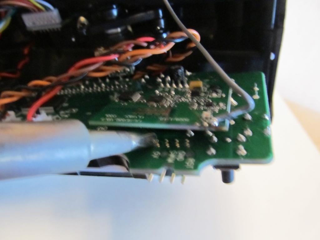
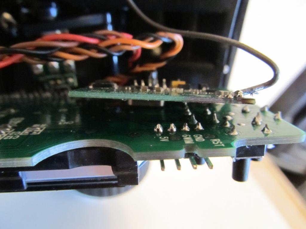
3 No glue past this line Step 4: Ok now towards the button side of the screen you ll see 4 holes spaced at.1. This is where the 4 pin header goes, Install the short pins into the holes with the long pins pointed to the antenna side of the case then I suggest putting a dab of hot glue on each end of the header, make sure no glue gets on the front side, it s ok if it touches the backside pins, although try to avoid this as well. It s hard to see the glue in the second picture, so the arrows point to where to put the glue. Step 5: Ok now gently lift the board and pull towards the front. This is to pull the power button out of its hole to lift the board up and out. Ok now gently twist the board up towards the st wheel. To expose the bottom side of the header. Now with the bottom side of the hear exposed lets solder it. To solder a header to a circuit board; pre tin your soldering iron tip lightly, position your iron on one side of the pin so it touches both the pin and solder pad. Then let it heat both for.5-1 second. Now with your iron still touching both apply solder to the other side of the pin, until it melts completely around and down through the hole. Now clean your iron tip. Check to make sure this didn t melt your hot glue and make your header un level, if it did then reheat the joint and push the header back down. Now repeat the steps above for the other 3 pins. 3
4 4

5 Step 6: Ok now flip your board back over and slide the power button back into its hole and push the whole board back down level. Now you ll see there s no way you can plug into the header, that s because you have to cut a slot. Look at the header and at its furthest points take a pair of snips/cutters and cut one step down into the plastic chances are the front side of the cut will bend/flex out to the thinnest point near where the screw goes through, this is ok. Now take a pair of pliers and bend the plastic towards you, you may need to lightly wiggle it back and forth so it breaks off. This new slot will be wre your plug enters the radio to program it. Now it probably doesn t look real neat or very professional. So what I like to do is take a razor knife or hobby knife, and cut all the un even white stretched plastic off into a nice level surface. After you have cut it plug in your cord and make sure it fits, I also like to take my razor and cut a mark in so I know where the plug needs to be, so ones a put the cover back on I don t have to worry about getting it on the wrong pins. 5

6 6


7 Step 7: Put the button covers back on lift antenna up, and pop the top cover back on, so the latches snap back on. Now plug the cord back in, make sure it fits, if it does install the 4 screws and pat yourself on the back because you just finished installing the hack kit to your radio. Now lets program it. 7

8 Step 8: Now you need to download and install the programming software, ST visual programmer. It can be download with/from this link If you are running windows 7 and possibly vista you may need to install this patch as well, which can be found at this link Make sure restart your computer after you install. Once you have rebooted your computer, open up ST Visual Programmer and make sure you have these settings, first time you open it, it should let you choose, however if it doesn t, click on the configure tab, then configure ST visual programmer. 8


9 Step 9: Close out of STVP; now plug your radio into the programmer. There is a triangle on the plugs of your harness. These arrows need to be on the SB1 side on your programmer, and towards the BND button on the gt3b side it s also the black wire. Now plug the programmer into the computer with the supplied USB cord. Now open up STVP. o Click File, open, Select the firmware you want to use. o Now click program, Current tab. There should be a status bar on the bottom. It will program then verify. Don t do anything till it says verification complete. 9
10 Step 10: Now unplug your radio, and start setting up your models, have fun. 10
Installation tutorial for Console Customs Xbox ONE MaxFire ONE V2 PCB
 Installation tutorial for Console Customs Xbox ONE MaxFire ONE V2 PCB This tutorial is designed to aid you in installation of a console customs MaxFire ONE V2 Circuit board in the newer Xbox One Controllers
Harmony Remote Repair
 Harmony Remote Repair harmonyremoterepair.com How to install your new Harmony One Front Cover/Touch Screen Important! Before you begin working on your Harmony One, you must discharge any static electricity
Explorer Wiring Kit (assembled)
") Explorer Wiring Kit (assembled) For Vintage, Firestorm & Standard Series Please Read All Instructions Before Beginning. Tools you will need: Soldering Iron (35 watt preferably) Solder Wet Sponge Wire Clippers
Explorer Wiring Kit (assembled) For Vintage, Firestorm & Standard Series Please Read All Instructions Before Beginning. Tools you will need: Soldering Iron (35 watt preferably) Solder Wet Sponge Wire Clippers
Electronics Merit Badge Class 4. 12/30/2010 Electronics Merit Badge Class 4 1
 Electronics Merit Badge Class 4 12/30/2010 Electronics Merit Badge Class 4 1 Soldering Safety Note: A Soldering Iron gets hotter than 374 F. Do not touch the soldering iron s metal parts or you will receive
01. Parts. Blink v1.1. Battery Holder x1. Red LED x1 Green LED x1 Blue LED x1. Resistors x3. Battery x1. Blink PCB x1. Push Button Switchers x3
 Blink L1 L2 L3 01. Parts Battery Holder x1 Red LED x1 Green LED x1 Blue LED x1 Resistors x3 Learn to Solder Kit Battery x1 L1 L2 L3 Blink PCB x1 S3 Push Button Switchers x3 02. Tools RECOMENDED Soldering
Custom Front Panel Upgrade Instructions
 Custom Front Panel Upgrade Instructions Here are the directions for upgrading your SP-II to an SP-IIB, with a custom blackanodized front panel and engraved lettering. There are only forty SP-IIB s in existence
FlexRC Mini Owl - Extreme FPV Proximity Racing Drone - DIY Build Instructions
 FlexRC Mini Owl - Extreme FPV Proximity Racing Drone - DIY Build Instructions This guide will walk you through the detailed build steps using the FlexRC Mini Owl Extreme FPV Racing Drone DIY Kit. The kit
ArduTouch Music Synthesizer
 ArduTouch Music Synthesizer Assembly Instructions rev C Learn To Solder download for free at: http://mightyohm.com/soldercomic The following photos will show you how to solder. But feel free to download
Powerbook G3 Lombard (1999) USB Repair Manual
 USB Repair Manual") Powerbook G3 Lombard (1999) USB Repair Manual Copyright 2003 Powerbookmedic.com. All rights reserved. Any portion of this manual may not be copied, reproduced, or distributed without the express written
Powerbook G3 Lombard (1999) USB Repair Manual Copyright 2003 Powerbookmedic.com. All rights reserved. Any portion of this manual may not be copied, reproduced, or distributed without the express written
Stratitec S5202A Snap-in Circuit Breaker
 Stratitec S5202A Snap-in Circuit Breaker Replacement This guide will show the user how to remove and replace a SS-001 snap in circuit breaker for a surge protector. Written By: rainbentrott ifixit CC BY-NC-SA
Lesson 2: Soldering. Goals
 Introduction: Its time to learn how to solder. So you have met all the components needed to make a DIY Gamer, now it s time to put it together. Soldering is joining the components to the printed circuit
ScaleRCHelis.com V Light Controller Kit
 Thank you for purchasing the ScaleRCHelis.com V1.1 450 Light Controller Kit. This is something you can build in under a hour with some simple soldering equipment. Your kit will include all the parts necessary
OpenROV. Guide 3 - Electronics. We will now move to the assembly of the electronics that will control the ROV. Written By: OpenROV
 OpenROV Guide 3 - Electronics We will now move to the assembly of the electronics that will control the ROV. Written By: OpenROV 2017 openrov.dozuki.com Page 1 of 33 INTRODUCTION We will introduce soldering
iphone 1st Generation Battery Replacement Written By: irobot ifixit CC BY-NC-SA Page 1 of 15
 Written By: irobot ifixit CC BY-NC-SA www.ifixit.com Page 1 of 15 INTRODUCTION Battery not lasting long? Swap it out (requires soldering). TOOLS: Probe and Pick Set (1) Desoldering Braid (1) SIM Card Eject
How to install an aftermarket stereo/navigation
 How to install an aftermarket stereo/navigation As most of you know, the 2002 (and others) Sport Trac has the 1 ½ DIN radio. This makes for some narrow choices when putting in a radio with navigation.
Installation tutorial for Console Customs PS3 TrueFire Standard Rapid fire Microchip for Sixaxis and Dualshock 3 controllers
 Installation tutorial for Console Customs PS3 TrueFire Standard Rapid fire Microchip for Sixaxis and Dualshock 3 controllers This tutorial is designed to aid you in installation of a console customs rapid
Soldering is easy. here's how to do it. Andie Nordgren (Comics adaptation) Jeff Keyzer. by: Mitch Altman (soldering wisdom) (Layout and editing)
 Jeff Keyzer. by: Mitch Altman (soldering wisdom) (Layout and editing)") Soldering is easy here's how to do it by: Mitch Altman (soldering wisdom) Andie Nordgren (Comics adaptation) Jeff Keyzer (Layout and editing) Download this comic book and share it with your friends! Distribute
Soldering is easy here's how to do it by: Mitch Altman (soldering wisdom) Andie Nordgren (Comics adaptation) Jeff Keyzer (Layout and editing) Download this comic book and share it with your friends! Distribute
Installation tutorial for Console Customs Xbox Mode Dual Button (RFX-5B) Rapid fire Microchip for all Wired and Wireless controllers
 Rapid fire Microchip for all Wired and Wireless controllers") Installation tutorial for Console Customs Xbox 360 5-Mode Dual Button (RFX-5B) Rapid fire Microchip for all Wired and Wireless controllers This tutorial is designed to aid you in installation of a console
Installation tutorial for Console Customs Xbox 360 5-Mode Dual Button (RFX-5B) Rapid fire Microchip for all Wired and Wireless controllers This tutorial is designed to aid you in installation of a console
Repairing Microsoft Wedge Touch Mouse Battery Cover Retaining Clip
 Repairing Microsoft Wedge Touch Mouse Battery Cover Retaining Clip Disassembly, repair and reassembly of Wedge Touch mouse when the battery cover will not stay closed. Also is a good guide to repair other
gently pry up all your door switches.. disconnect them.. same with the mirror control on the drivers side..
 How To Recover Door Panels By: Crispy SUPPLY/TOOL LIST NEEDED Dremel with drill cutter attachment (or drill with drill bit) contact cement 1/2 inch self tapping screws Carpet/Headliner spray on glue Phillips
Instructions for Lighting an S Scale Caboose
 Instructions for Lighting an S Scale Caboose The S Scale Caboose lighting kit is adaptable for most caboose models of rolling stock including American Flyer (TM) and contains the same components as found
Installation tutorial for Console Customs Xbox 360 Dual Rapid fire Microchip for wired and wireless controllers (all versions)
") Installation tutorial for Console Customs Xbox 360 Dual Rapid fire Microchip for wired and wireless controllers (all versions) This tutorial is designed to aid you in installation of a console customs
Installation tutorial for Console Customs Xbox 360 Dual Rapid fire Microchip for wired and wireless controllers (all versions) This tutorial is designed to aid you in installation of a console customs
Standard Kit #1 (3-way switch)
") Standard Kit #1 (3-way switch) Please Read All Instructions Before Beginning. Tools you will need: Soldering Iron (35 watt preferably) Solder Wet Sponge Wire Clippers 3/8 Drill Bit 1/4 Drill Bit Variable
Standard Kit #1 (3-way switch) Please Read All Instructions Before Beginning. Tools you will need: Soldering Iron (35 watt preferably) Solder Wet Sponge Wire Clippers 3/8 Drill Bit 1/4 Drill Bit Variable
Value Location Qty Transistors 2N5485 Q1, Q2, 4 Q3, Q4 2N5087 Q5 1. Trim Pots 250k VTRIM 1. Potentiometers C500k Speed 1. Toggle Switch On/On Vibe 1
 P-90 BUILD INSTRUCTIONS Thank you for your purchase of our P-90 kit! We have completely redesigned our entire line of kits to be the most user friendly, while still maintaining their same great sound!
BrewsBySmith.com STC DIY Kit
 BrewsBySmith.com STC-1000 + DIY Kit Contact Information: Greg Smith www.brewsbysmith.com greg@boostbysmith.com I. Hardware Included: STC-1000 flashed with latest software (v1.06 currently) (if purchased)
Motorola E815 / E816 Disassembly / Assembly Guide. Ver. 1.1 By Chubbs_WA
 Motorola E815 / E816 Disassembly / Assembly Guide Ver. 1.1 By Chubbs_WA April 10, 2007 Table of Contents Disassembly Tools needed 3 Disassembly for dummies 4 Just a note 5 Disassembly of keypad housing
Pingable Envelope Generator
 Pingable Envelope Generator Kit Builder's Guide for PCB v1.0.3 4mspedals.com PEG This guide is for building a Pingable Envelope Generator (PEG), which is an intermediate-level kit. You should be confident
Value Location Qty Potentiometers C1M Distortion 1 A10k Volume 1. Footswitch 3PDT SW1 1. Jacks 1/4 Mono 2 DC Power 1
 Distortion BUILD INSTRUCTIONS Thank you for your purchase of our Distortion+ kit! We have completely redesigned our entire line of kits to be the most user friendly, while still maintaining their same
Installing Your New Creature From The Black Lagoon Tail Light DMD Panel MOD
 Installing Your New Creature From The Black Lagoon Tail Light DMD Panel MOD A few things before we start: The wooden speaker panel provided in this MOD was manufactured using a Precision CNC machine and
Intellivision A/V Mod Installation Guide
 Intellivision A/V Mod Installation Guide This document will guide you through installing your Intellivision A/V Mod Kit to your Intellivision I, II, and III game consoles. Installation is basically the
Any Questions? Contact us or BSA Atomic Blinkie
 BSA Atomic Blinkie The heart of this blinkie is a tiny electronic chip embedded in each of the three LEDs. When power is applied, the chip tells the LED to turn on and off, or fade different colors By
The Useless Machine. DIY Soldering Edition. Instruction Guide v0004
 The Useless Machine DIY Soldering Edition Instruction Guide v0004 TM For the best outcome, follow each step in order. We recommend reading this guide entirely before you get started. Tools required: Soldering
Smartlamp SINGLE LED Kit - Construction Manual
 Smartlamp SINGLE LED Kit - Construction Manual With this construction manual and a Smartlamp Single LED Kit you can assemble your own solar lamp. It is recommended to first read the instructions before
Telecaster Wiring Kits Please Read All Instructions Before Beginning. Tools you will need: Soldering tips: Removing Current Wiring: Step 1. Step 2.
 Telecaster Wiring Kits Please Read All Instructions Before Beginning. Tools you will need: Soldering Iron (35 watt preferably) Solder Wet Sponge Wire Clippers Wire Strippers 3/8 Drill Bit 5/32 Drill Bit
Lesson 2: Soldering. Goals
 Introduction: Its time to learn how to solder. So you have met all the components needed to make a DIY Gamer, now it s time to put it together. Soldering is joining the components to the printed circuit
To all Yaesu VR500 Owners
 To all Yaesu VR500 Owners There will surely come a time when the rotary clicking channel selector switch will get so worn, that the radio channel change will either refuse to go forwards, miss channels
3DO Memory Battery Replacement Guide Page 1 of 13. 3DO Memory Battery Replacement Guide
 3DO Memory Battery Replacement Guide Page 1 of 13 3DO Memory Battery Replacement Guide Thank you for your purchase of a 3DO memory battery from Nintendo Repair Hut. This guide is designed to help you through
DIY Instructions For NGPC Front Light Installation using the Gameboy Advanced SP Front Light
 DIY Instructions For NGPC Front Light Installation using the Gameboy Advanced SP Front Light Tools you will need: Phillips Screwdriver Flat head Screwdriver Tri-wing Screwdriver Exacto Knife Soldering
66 Dodge Charger (and others) Tach board
 Tach board") 66 Dodge Charger (and others) Tach board Introduction: This board replaces the original tachometer driver board in the 66 charger and other cars that use electronics external to the tachometer. The board
66 Dodge Charger (and others) Tach board Introduction: This board replaces the original tachometer driver board in the 66 charger and other cars that use electronics external to the tachometer. The board
FACTORY CAT TOMCAT CORPORATION
 FACTORY CAT RPS TOMCAT CORPORATION Artificial Turf and Carpet Sweeping Install Kit #349-641 & #349-642 1. Detach batteries so that there is no power running through the machine before starting. 2. Start
5X Racing Miata Radio Delete Plate Installation Instructions
 5X Racing 99-05 Miata Radio Delete Plate Installation Instructions Thank you for purchasing our unique, aluminum race inspired radio delete plate for your 1999-2005 Mazda Miata! These instructions will
Golf Trolley Workshop (Devon)
") Golf Trolley Workshop (Devon) Powerpole General Assembly Instructions Assemble the red and black plastic housings together correctly on the first try, they fit snugly and can be difficult to get apart.
Golf Trolley Workshop (Devon) Powerpole General Assembly Instructions Assemble the red and black plastic housings together correctly on the first try, they fit snugly and can be difficult to get apart.
PSU for LawMate 500mW Transmitters. Assembly and Operation Manual
 PSU for LawMate 500mW Transmitters Assembly and Operation Manual Introduction Thank you for purchasing LawMate 500mW Power Supply. This power supply was specifically designed for the 500mW LawMate transmitter
ENGR 40M Project 2a: Useless box
 ENGR 40M Project 2a: Useless box Prelab due 24 hours before your section, April 16 19, 2018 Lab due before your section, April 24 27, 2018 1 Objectives In this lab, you ll assemble a useless box like the
Modification of USB Sound Card for Asterisk app_rpt Use
 Modification of USB Sound Card for Asterisk app_rpt Use First off a huge thank you to Steve for providing the original notes on how to modify a USB sound card. (http://images.qrvc.com/usbfob.pdf) These
Warning: CHOKING HAZARD -Small Parts. Not for Children Under 9 yrs. Kit Recommended for Ages 12 and up.
 The Original Warning: CHOKING HAZARD -Small Parts. Not for Children Under 9 yrs. Kit Recommended for Ages 12 and up. Table of Contents Soldering.. 3 How the WASP Works.. 7 The Build...... 12 Troubleshooting......30
Sega CD 2 CMOS Battery Replacement Guide Page 1 of 7. Sega CD 2 CMOS Battery Replacement Guide
 Sega CD 2 CMOS Battery Replacement Guide Page 1 of 7 Sega CD 2 CMOS Battery Replacement Guide Thank you for your purchase of a Sega CD 2 CMOS battery replacement kit from Nintendo Repair Hut. We appreciate
LED Cup Holder Lights Installation Guide
 LED Cup Holder Lights Installation Guide (20112015 Kia Optima) Thanks for purchasing this LED Cup Holder Light Kit! If you have any questions or feedback please email us direct at Sales@K5OptimaStore.com
EA6500 Antenna Installation Instructions:
 Thank you for purchasing the 6 Antenna Mod Kit for your Linksys router. First we will show you how to install the antennas for your router. Next we will teach you how to setup the DD-WRT firmware which
Team Xecuter Joycon Mod By: XxWiReDxX
 Team Xecuter Joycon Mod By: XxWiReDxX Works With Every Switch SX OS Works with every Nintendo Switch and every firmware version! Play Every Game With SX OS you can play all your favorite games straight
Star Trek TOS communicator upgrade kit Install instructions Hyperdyne Labs 2002
 Star Trek TOS communicator upgrade kit Install instructions Hyperdyne Labs 2002 Package Your package should include: Assembled TOS sound/motor/light board with LEDs and sound chip Moiré motor 9V snap connector
The Empeg and Riōcar Illumination Kit Installation and User s Manual
 The Empeg and Riōcar Illumination Kit Installation and User s Manual Last Updated: October 13, 2005 Table of Contents READ THIS FIRST!!!...1 Introduction to the Installation Process...3 Install the Hijack
BL-ER-P Ethernet Radio Unit for Pedestal Installation Guide
 Assemble the Antenna Riser 1. Remove the antenna riser assembly and the antenna from its packaging. 2. Remove the plastic cap, the nut, and the lock washer from the stem of the antenna. 3. Put the stem
PRINTER REPAIR ARTICLE HP LJ 4345/M4345 Swing Plate Replacement
 a1 output bin a2 DUPLEXER a4 FORMATTER COVER a5 FORMATTER a3 fuser entr. guide PRINTER REPAIR ARTICLE HP LJ 4345/M4345 Swing Plate Replacement Grinding noise near the fuser means it is time to replace
STEP 1 : DESTROYER FRONT BUMPER INSTALL GATHER YOUR TOOLS AND LAY OUT YOUR PARTS... *shorty bumper to show hardware* Tools Required:
 DESTROYER FRONT BUMPER INSTALL JL STEP 1 : GATHER YOUR TOOLS AND LAY OUT YOUR PARTS... Tools Required: - Utility knife - 11/16 Deep socket - Ratchet - 11/16 Crescent wrench - Ratchet Extension - 1/4 socket
Assembly instructions for the CS-1 ChemShield
 Page 1 Of 6 Assembly instructions for the CS-1 ChemShield What is S.M.D SMD=Surface mount devices, like all the components does not have leads, but gets soldered onto flat solder pads. The CS-1 assembly
HP M506/MFP M527 CF-287A/X
 HP M506/MFP M527 CF-287A/X TONER CARTRIDGE REMANUFACTURING INSTRUCTIONS HP CF-287A/X TONER CARTRIDGE REMANUFACTURING THE HP LASERJET ENTERPRISE M506/MFP M527 CF-287A/X TONER CARTRIDGE By Mike Josiah and
tinycylon Assembly Instructions Contents Written by Dale Wheat Version August 2016 Visit dalewheat.com for the latest update!
 tinycylon Assembly Instructions Written by Dale Wheat Version 2.1 10 August 2016 Visit dalewheat.com for the latest update! Contents Assembly Instructions...1 Contents...1 Introduction...2 Quick Start
U-bass Kit Assembly Instructions
 U-bass Kit Assembly Instructions Compiled by playubass.com This guide is built from the instructions found here: http://kalabrand.com/ubass-kit/index.html Tools Needed 5/8 (16 mm) Wrench 7/16 (~11 mm)
Standard Kit #1 (5-way switch)
") Standard Kit #1 (5-way switch) Please Read All Instructions Before Beginning. Tools you will need: Soldering Iron (35 watt preferably) Solder Wet Sponge Wire Clippers 3/8 Drill Bit 1/4 Drill Bit Variable
Standard Kit #1 (5-way switch) Please Read All Instructions Before Beginning. Tools you will need: Soldering Iron (35 watt preferably) Solder Wet Sponge Wire Clippers 3/8 Drill Bit 1/4 Drill Bit Variable
INSTALL/REMOVAL INSTRUCTIONS: WINDOW REGULATOR
 REMOVAL/INSTALL OF WINDOW REGULATOR (741-584) Ford Focus 2000-2007 General Tech Tips: Use painter s tape rather than duct tape to secure window. It will not damage paint or leave sticky residue. A plastic
PRO 400 M401 MFP M425 CF-280A/X TONER CARTRIDGE REMANUFACTURING INSTRUCTIONS
 HP PRO 400 M401 MFP M425 CF-280A/X TONER CARTRIDGE REMANUFACTURING INSTRUCTIONS HP CF-280A/X TONER CARTRIDGE REMANUFACTURING THE HP LASERJET PRO 400 M401/MFP M425 (CF-280A/X) TONER CARTRIDGE By Mike Josiah
EXTREME LOAD no. ONE
 P R E C I S I O N D E S I G N C O 1601 - EXTREME LOAD no. ONE in HO scale Kit Features: 18'-8" x 7'-1" x 18'-9" Oversize Load 65.62mm (2.583") actual height Bolt Head and Bolt Hole Details Welded Load
iphone 6 Chargeport REPAIR GUIDE Version Edition
 iphone 6 Chargeport REPAIR GUIDE Version 1 2016 Edition IPHONE 6 CHARGEPORT REPAIR GUIDE LCD AND DIGITIZER REPLACEMENT RiAna Soto Repair Training Specialist rsoto@cellairis.com FOR EVERY REPAIR MAKE SURE
626 - Mazda MX-6 - Mazda
 Factory Radio Other Documents Available For This Vehicle: No additional documents available at this time Adobe Acrobat Reader Printing Tips: 1) Select FLE then PRNT and select your printer. 2) n the print
Installing the 3 Indexer: PRS Standard Tools
 888-680-4466 ShopBotTools.com Installing the 3 Indexer: PRS Standard Tools Copyright 2016 ShopBot Tools, Inc. page 1 Copyright 2016 ShopBot Tools, Inc. page 2 Table of Contents Route Cable into Box...5
Mac mini (PowerPC) Hard Drive Replacement
 Hard Drive Replacement") Mac mini (PowerPC) Hard Drive Replacement Written By: irobot INTRODUCTION Upgrade your storage with a new hard drive. TOOLS: 1.5" Thin Putty Knife (1) Phillips #00 Screwdriver (1) Phillips #1 Screwdriver
Mac mini (PowerPC) Hard Drive Replacement Written By: irobot INTRODUCTION Upgrade your storage with a new hard drive. TOOLS: 1.5" Thin Putty Knife (1) Phillips #00 Screwdriver (1) Phillips #1 Screwdriver
EmagiKit. Privacy Pod Plus. Quiet. Easy. Affordable. INSTRUCTIONS ASSEMBLY
 EmagiKit Privacy Pod Plus Quiet. Easy. Affordable. INSTRUCTIONS ASSEMBLY DIMENSIONS AND COMPONENTS 47 47 Ceiling Unit 2-B 2-L 2-R Glass Door Corner Trim Door Handle 90 Adjustable Height Work Surface 1-B
Tools needed: Phillips screwdriver, flat blade screwdriver, rubber cement, clean hands.
 Installing the New Face for the Volvo 740 Turbo Vacuum/Boost Gauge INTRODUCTION: These instructions will guide you through the installation of this new face for your existing vacuum/boost gauge. It is
01. Parts. LEDs x2. On/Off Switch x1. Jitterbug PCB x1. Vibration Motor x1. Battery Holder x1. Wire x1. 3V Coin Cell Battery x1
 01. Parts LEDs x2 Jitterbug PCB x1 On/Off Switch x1 Vibration Motor x1 Battery Holder x1 Wire x1 3V Coin Cell Battery x1 02. Tools RECOMENDED Soldering Iron 110V 60W Soldering Iron FINE SOLDER WIRE Flush
Eo Classical - Specification and Features
 Eo Classical - Specification and Features Folded dimensions 420mm long x 100mm high x 130mm wide. Weight 1.5 kg. Unfolded, overall 820 mm x 360 mm with contour wings in place. String scale length: 650
Written By: Brook Drumm
 Simple 1401 Assembly For kits produced between 1/15/14-6/1/14. This guide is for kits with the Fan Shroud. Instructions for metal and wood extruder (and bed) included below. Written By: Brook Drumm TOOLS:
Mono Amplifier. LM386 Headphone Amp
 Mono Amplifier LM386 Headphone Amp Layout On/Off Switch - cuts power to the circuit Mono Input Jack: use either L or R or solder together Schematic Step 1 - Parts List 1.) R1-10ohm Resistor - Brown Black
Installation Instructions for FC2 & FC15 Forward Controls for the Super Magna
 Installation Instructions for FC2 & FC15 Forward Controls for the Super Magna It is highly recommended that you use a thread lock compound such as Loctite brand on all threads to keep them from vibrating
RF Current Meter Kit
 Kit When assembled, this kit provides you with a simple but effective means of measuring the current in antenna wires, and of looking for braid currents on coax feeders. The more current you can get flowing
Never power this piano with anything other than a standard 9V battery!
 Welcome to the exciting world of Digital Electronics! Who is this kit intended for? This kit is intended for anyone from ages 13 and above and assumes no previous knowledge in the field of hobby electronics.
GEN II Toyota Prius Back Door Opener Switch Replacement & License Plate Lights
 GEN II Toyota Prius Back Door Opener Switch Replacement & License Plate Lights Rubber Surface of Switch had Degraded to Tar-like Substance Vehicle Manufacture Date 10/06 OLD SWITCH IN GARNISH SWITCH REMOVED
Cover Page. Factory Radio Other Documents Available For This Vehicle:
 Factory Radio Other Documents Available For This Vehicle: No documents available at this time Adobe Acrobat Reader Printing Tips: 1) Select FLE then PRNT and select your printer. 2) n the print options
PROSTEER BALL JOINT REBUILD INSTRUCTIONS V1.0
 DYNATRAC PRODUCTS 2003-2010 4X4 DODGE 2500/3500 HEAVY DUTY BALL JOINT PROSTEER BALL JOINT REBUILD INSTRUCTIONS V1.0 WARNING: Improper use or installation of this product can cause major failures that could
Lighthouse Beginner s soldering kit
 Lighthouse Beginner s soldering kit Kit contains: 1 x 220 ohm resistor (Red, Red, Black) 1 x 82k ohm resistor (Grey, Red, Orange) 2 x 220k ohm resistors (Red, Red, Yellow) 2 x Diodes 1 x Power switch 1
Assembly Instructions: Kit #5
 Assembly Instructions: Kit #5 1. Insert the T-pin into one of the caps. 2. Insert the rotor core into the same cap as shown below. Apply some pressure to push the rotor core approximately 1/2" (10-12 mm)
The wick in your heater needs replacing if, after repeated cleanings, any of the following conditions still exist:
 WICK REPLACEMENT The wick in your heater needs replacing if, after repeated cleanings, any of the following conditions still exist: Slow to light, hard movement of the wick adjuster knob, kerosene odor
Written By: Darren Chan
 Sega Dreamcast Controller Port Replacement Written By: Darren Chan ifixit CC BY-NC-SA www.ifixit.com Page 1 of 10 INTRODUCTION Replacing the F1 fuse on the controller board of the Sega Dreamcast. Soldering
The Bowflex Revolution XP Home Gym Assembly Instructions. P/N: Rev ( /0 )
") P/N: 001-7057 Rev ( /0 ) The Bowflex Revolution XP Home Gym Assembly Instructions 2 Table of Contents Before You Start... 2 Tools You Will Need / Hardware Contents... 3 Box Contents... 6 Assembling Your
P/N: 001-7057 Rev ( /0 ) The Bowflex Revolution XP Home Gym Assembly Instructions 2 Table of Contents Before You Start... 2 Tools You Will Need / Hardware Contents... 3 Box Contents... 6 Assembling Your
Learn to solder electronics with the Maker
 Learn to solder electronics with the Maker Shed Solder Badge! How to assemble the Maker Shed Badge kit. Written By: Alexander ifixit CC BY-NC-SA www.ifixit.com Page 1 of 19 INTRODUCTION The Maker Shed
ANDERSON POWERPOLE CONNECTORS FOR HAM OPERATORS
 ANDERSON POWERPOLE CONNECTORS FOR HAM OPERATORS The Anderson Powerpole connector is a very good connector to sharing connections between users for such things as batteries, radios, chargers and other DC
Solder is a metallic glue that holds the parts together and forms a connection that allows electrical current to flow.
 Proper Soldering & Desoldering High Performance Ultrasonic Range Finders Techniques of a MaxBotix Sensor Materials Needed for Soldering Goggles Hands-free clamp Wire stripper Soldering iron with stand
Rapid LED NanoCube 28 CF Quad Retrofit
 1 Rapid LED NanoCube 28 CF Quad Retrofit Contents Foreword... 1 Outline... 2 Hood Preparation... 2 Attaching LEDs to Heatsink and Wiring LEDs Together... 6 Thermal Grease... 6 Soldering Notes... 7 Tinning
The Useless Machine. Parts Only - Build Guide v0001
 TM The Useless Machine Parts Only - Build Guide v0001 For the best outcome, follow each step in order. We recommend reading this guide entirely before you get started. Tools required: One phillips screwdriver,
Atari Lynx I Capacitor Replacement Kit Installation Guide Page 1 of 15. Atari Lynx I Capacitor Replacement Kit Installation Guide
 Atari Lynx I Capacitor Replacement Kit Installation Guide Page 1 of 15 Atari Lynx I Capacitor Replacement Kit Installation Guide Thank you for your purchase of an Atari Lynx I capacitor replacement kit
Bill of Materials: Metronome Kit PART NO
 Metronome Kit PART NO. 2168325 The metronome kit allows you to build your own working electronic metronome. Features include a small speaker, flashing LED, and the ability to switch between several different
The Centimani Servo Power Board
 The Centimani Servo Power Board Email: srlm@srlmproductions.com Abstract This document discusses the procedure required to build a Centimani Servo Power Board and the capabilities of the board. This board
Heartboard PCB Assembly Instructions
 Heartboard PCB Assembly Instructions Thanks for purchasing a Heartboard! These instructions will guide you through assembling and testing the Heartboard. Let s get started! Stuff you need Soldering iron
PSU V2 for LawMate 500mW Transmitters. Assembly and Operation Manual
 PSU V2 for LawMate 500mW Transmitters Assembly and Operation Manual Introduction Thank you for purchasing the V2 LawMate 500mW Power Supply. This power supply was specifically designed for the 500mW LawMate
DYNATRAC BALL JOINT REBUILD INSTRUCTIONS V5.0
 DYNATRAC PRODUCTS 2007-2018 JEEP JK HEAVY DUTY BALL JOINT JP44-2X3050-C DYNATRAC BALL JOINT REBUILD INSTRUCTIONS V5.0 WARNING: Improper use or installation of this product can cause major failures that
BIG CEE. ENGINEERING 627 N Michigan Ave #5 Pasadena, CA
 Garmin Emap power adapter housing BIG CEE ENGINEERING 627 N Michigan Ave #5 Pasadena, CA 91106 bigcee@bigcee.com www.bigcee.com This kit allows you to remove the circuit board from your Emap 12V adapter
Repairing your Porsche 928 Central Warning System (CWS) controller
 controller") Repairing your Porsche 928 Central Warning System (CWS) controller Disclaimer: This procedure is for a 1984 Porsche 928 S controller. Overview: Under the left foot pedal (dead pedal) of the Porsche 928
Repairing your Porsche 928 Central Warning System (CWS) controller Disclaimer: This procedure is for a 1984 Porsche 928 S controller. Overview: Under the left foot pedal (dead pedal) of the Porsche 928
Removing and Replacing the Y-truck
 Service Documentation Removing and Replacing the Y-truck To remove and replace the Y-truck you will need the following tools: 4mm Allen wrench 12mm stamped flat wrench #2 Phillips screwdriver (magnetic
Xbox360 Slim Dismantling Instructions
 Xbox360 Slim Dismantling Instructions These instructions will show you how to open the console to replace the DVDrom drive, laser and other internal parts. Opening your console will void your warrantee,
Guitarpedalkits.com Overdrive Pedal Build Instructions
 Page 1 Guitarpedalkits.com Overdrive Pedal Build Instructions Follow the instructions in this guide to build your very own DIY overdrive pedal from GuitarPedalKits.com. If you re a first time builder,