EA6500 Antenna Installation Instructions:
|
|
|
- Phyllis Smith
- 6 years ago
- Views:
Transcription

1 Thank you for purchasing the 6 Antenna Mod Kit for your Linksys router. First we will show you how to install the antennas for your router. Next we will teach you how to setup the DD-WRT firmware which will turn your $60 router into a powerful, highly configurable $600 router. EA6500 Antenna Installation Instructions: 1. Soldering required (here is the list of tools you will need) Phillips screw driver 8mm Socket with a ratchet 8mm Open End Wrench Soldering Gun Butter Knife Cutting pliers Needle


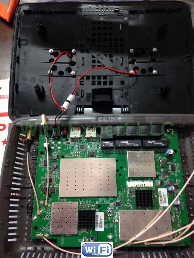
2 2. Open the unit. Remove the rubber stands first and then, all you need is a small Philips screw driver. The top and bottom of the router separate nicely with some help from you.

3 Wedge them apart with a kitchen knife or an object that is not sharp. Begin prying the unit open just down from the vent holes. The case is on tight, so pry open around the edges a little at a time. Be patient; she'll eventually pop open for you. If you brake couple of clips don t worry about it, happens to the best of us. 3. Remove the UFL antenna connectors. 4. Now you will have to unsolder factory cables and clip off the stock antennas (use small clippers). Please note you need to be patient with this as Factory soldering is very strong and takes time to unsolder. Heat up your soldering gun to 750 degrees and apply some additional solder on top to melt it faster. Be careful not to overheat the board when removing factory solder. It can damage your router permanently! Don t pull the cable too fast make sure it comes off easily as you can rip off the pad. Now with the board cleared and out of the case you can solder the IPX base onto the PCB board.

4 This requires patience and a steady hand You will be provided 3 IPX Base for PCB mount. 4. Solder the IPX base onto the PCB board. Use a small drop of crazy glue before soldering.
. 5.")
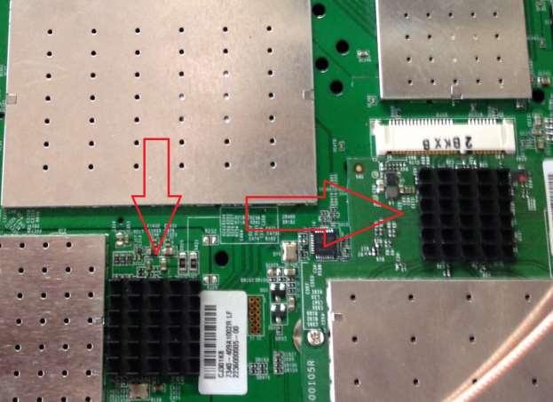
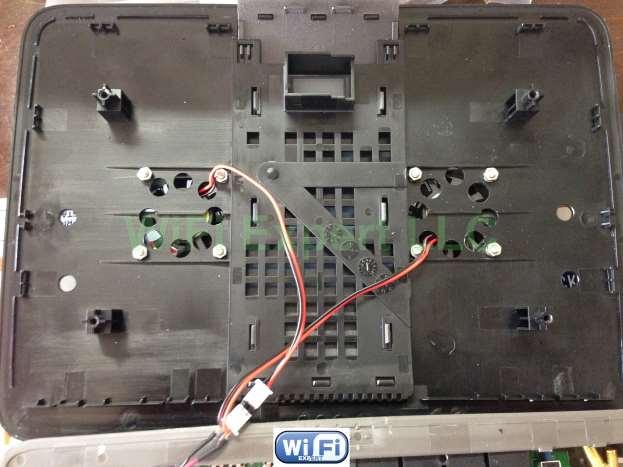
5 Make sure to solder the IPX base correctly with center pin to the center conductor and Ground to Ground. Look closely at the above picture; this is the correct way to solder the IPX base. We used opposite ground connection rather than using the same one (nice and smooth). 5. Now let s solder the Power cable for the fans, this step is very simple, see picture bellow.

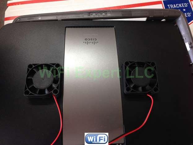
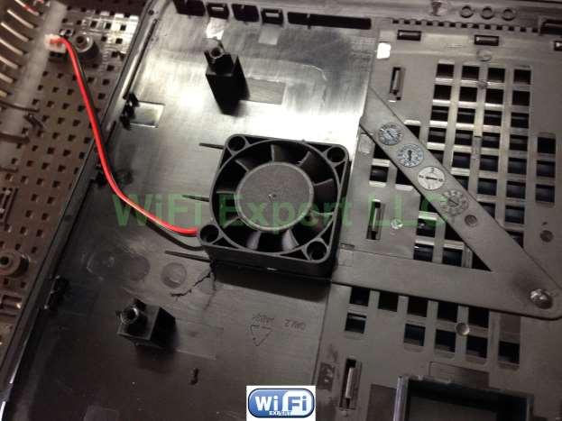
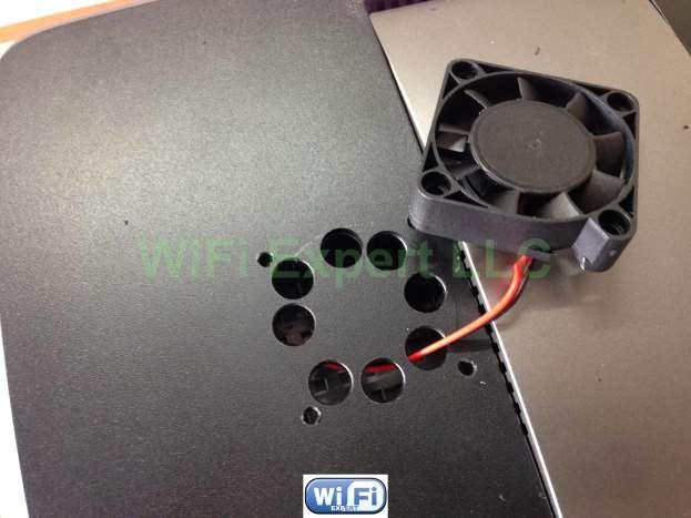
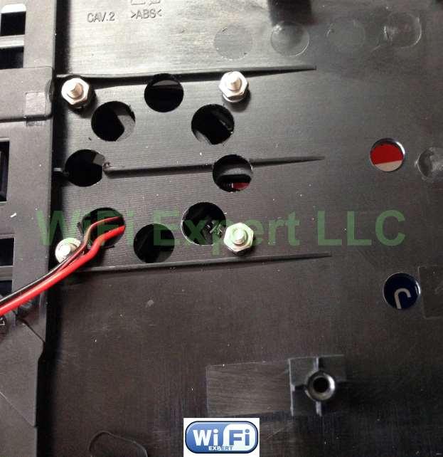
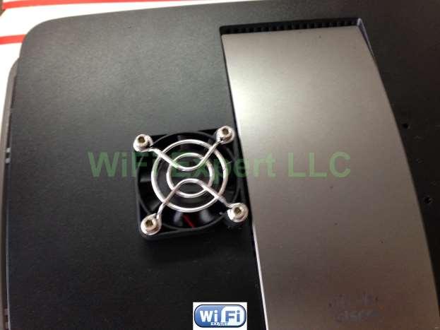
6 6. It s time to install the cooling fans and heat sinks, you can use the guides on the inside of the plastic to drill the 4 base holes for each fan, see below.
7
8
9
10
11
12
13
14
15
16

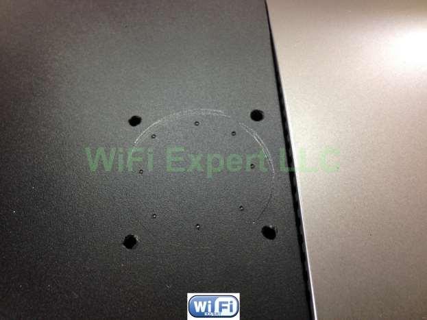
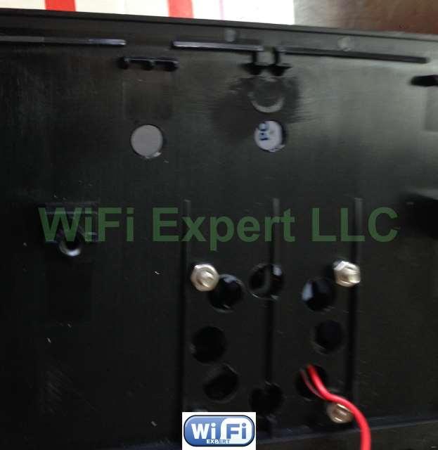
17 Now with the fans fully assembled you can drill all the antenna base holes. Drill a smaller hole first with a smaller bit and then go ahead and finish the drilling with the 1/4" drill bit. ¼ inch drill bit should be used for the final hole size
18
19
.")
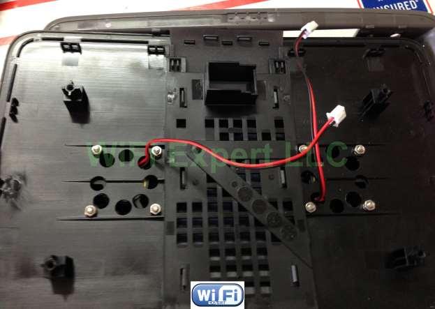
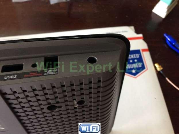
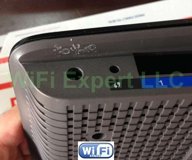
20 The top 4 holes need to be drilled in the center somewhat (use guides on the inside of the plastic, you can also use a ruler for price positioning). as shown below.

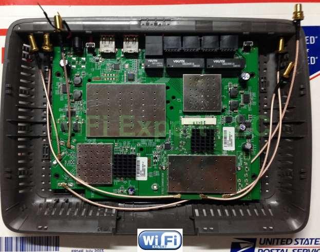
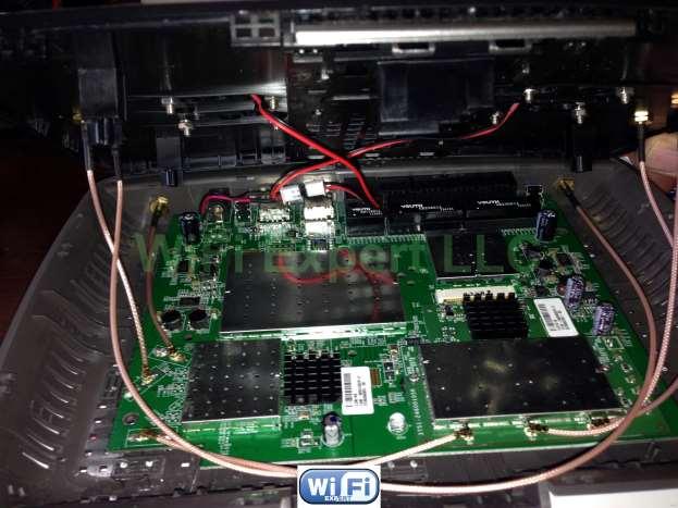
21 After drilling there will be a little plastic left around the inside hole that will need removing. Just use a small knife to remove the plastic. Now attach all the U.Fl cables as shown below:
22
23
24
. This router is HUGE and so easy to work with.")
25 Right side (corner) = 5ghz TX/RX Right side (mid)= 5ghz RX Right side (left)= 5ghz TX/RX Left side (top)=2.4ghz TX/RX Left side (mid)=2.4ghz RX Left side (bot)=2.4ghz TX/RX Screw all the nuts in place as shown above and close the router (make sure all the IPX connectors snap on in place). This router is HUGE and so easy to work with. Be sure the nut on the RP-SMA plug is nice and tight (use 8mm wrench and socket here), otherwise your antennas will flop. Power up the router to make sure the fans are spinning without making any dragging noise.

26 NOTE: When putting the case back together make sure none of the cables get pinched with screws or case. You can secure them in place by using clear tape. Enjoy DD-WRT: For optimal performance we recommend replacing the Linksys firmware with DD-WRT. This is a free third party firmware that will help turn your $60 router into a powerful, highly configurable $600 router. Read this thread: This is for advance users only.
E2500 Antenna Installation Instructions:
 Thank you for purchasing the Antenna Mod Kit for your Linksys router. First we will show you how to install the antennas for your router. We will also provide you with a tool that will help test the performance
Bushwacker Jeep Flat Style Fender Flares Front Pair
 Bushwacker Jeep Flat Style Fender Flares Front Pair Note: These instructions involve cutting parts of your vehicle. Please read all instructions prior to starting. Installation Time: 3-4 Hours Tools Required:
STEP 1 : DESTROYER FRONT BUMPER INSTALL GATHER YOUR TOOLS AND LAY OUT YOUR PARTS... *shorty bumper to show hardware* Tools Required:
 DESTROYER FRONT BUMPER INSTALL JL STEP 1 : GATHER YOUR TOOLS AND LAY OUT YOUR PARTS... Tools Required: - Utility knife - 11/16 Deep socket - Ratchet - 11/16 Crescent wrench - Ratchet Extension - 1/4 socket
Installation tutorial for Console Customs Xbox ONE MaxFire ONE V2 PCB
 Installation tutorial for Console Customs Xbox ONE MaxFire ONE V2 PCB This tutorial is designed to aid you in installation of a console customs MaxFire ONE V2 Circuit board in the newer Xbox One Controllers
Explorer Wiring Kit (assembled)
") Explorer Wiring Kit (assembled) For Vintage, Firestorm & Standard Series Please Read All Instructions Before Beginning. Tools you will need: Soldering Iron (35 watt preferably) Solder Wet Sponge Wire Clippers
Explorer Wiring Kit (assembled) For Vintage, Firestorm & Standard Series Please Read All Instructions Before Beginning. Tools you will need: Soldering Iron (35 watt preferably) Solder Wet Sponge Wire Clippers
Bushwacker Jeep Flat Style Fender Flares Rear Pair (JK Wrangler 2dr)
") Bushwacker Jeep Flat Style Fender Flares Rear Pair (JK Wrangler 2dr) Note: These instructions involve cutting parts of your vehicle. Please read all instructions prior to starting. Installation Time: 3-4
Bushwacker Jeep Flat Style Fender Flares Rear Pair (JK Wrangler 2dr) Note: These instructions involve cutting parts of your vehicle. Please read all instructions prior to starting. Installation Time: 3-4
Standard Kit #1 (3-way switch)
") Standard Kit #1 (3-way switch) Please Read All Instructions Before Beginning. Tools you will need: Soldering Iron (35 watt preferably) Solder Wet Sponge Wire Clippers 3/8 Drill Bit 1/4 Drill Bit Variable
Standard Kit #1 (3-way switch) Please Read All Instructions Before Beginning. Tools you will need: Soldering Iron (35 watt preferably) Solder Wet Sponge Wire Clippers 3/8 Drill Bit 1/4 Drill Bit Variable
Tools Required: - Utility knife - 11/16 Deep socket - Ratchet - 11/16 Crescent wrench - Ratchet Extension - 1/4 socket - Electrical tape
 DESTROYER FRONT BUMPER INSTALL JL STEP 1 : GATHER YOUR TOOLS AND LAY OUT YOUR PARTS... Tools Required: - Utility knife - 11/16 Deep socket - Ratchet - 11/16 Crescent wrench - Ratchet Extension - 1/4 socket
Bi-Color Signal Mirror Installation Instructions
 Bi-Color Signal Mirror Installation Instructions 2005-2009 Toyota Tacoma THE safety accessory of the 21 st Century. P/N 210-0141-0 Rev. A2 (3/30/09), BTV 2007 Muth Mirror Systems, LLC Page 3 of 13PplPage
BrewsBySmith.com STC DIY Kit
 BrewsBySmith.com STC-1000 + DIY Kit Contact Information: Greg Smith www.brewsbysmith.com greg@boostbysmith.com I. Hardware Included: STC-1000 flashed with latest software (v1.06 currently) (if purchased)
Instructions for Lighting an S Scale Caboose
 Instructions for Lighting an S Scale Caboose The S Scale Caboose lighting kit is adaptable for most caboose models of rolling stock including American Flyer (TM) and contains the same components as found
Ford Super Duty 4x4 CB Antenna Installation 2004 F250 4x4 XLT Sport Back to 2004 F250 Main Page
 Ford Super Duty 4x4 CB Antenna Installation 2004 F250 4x4 XLT Sport Back to 2004 F250 Main Page I wanted to install a CB in my truck but I didn't particularly like any of the typical antenna installation
AR.Drone 2 - Main Board External Antenna Modification Procedure. Document Number: EAM Check back for updates.
 Document Number: EAM-20130303-2 Check back for updates. 3/22/2013 NOTE: Along with this mod procedure, you will also need to: 1. Remove the Main Board. Refer to the Main Board Removal Procedure 2. Adapt
Standard Kit #1 (5-way switch)
") Standard Kit #1 (5-way switch) Please Read All Instructions Before Beginning. Tools you will need: Soldering Iron (35 watt preferably) Solder Wet Sponge Wire Clippers 3/8 Drill Bit 1/4 Drill Bit Variable
Standard Kit #1 (5-way switch) Please Read All Instructions Before Beginning. Tools you will need: Soldering Iron (35 watt preferably) Solder Wet Sponge Wire Clippers 3/8 Drill Bit 1/4 Drill Bit Variable
Rugged Ridge Front Bumper Winch Plate JK
 Rugged Ridge Front Bumper Winch Plate 13-17 JK Note: These instructions involve cutting parts of your vehicle. Please read all instructions prior to starting. Installation Time: 2-3 Hours Tools Required:
PSU for LawMate 500mW Transmitters. Assembly and Operation Manual
 PSU for LawMate 500mW Transmitters Assembly and Operation Manual Introduction Thank you for purchasing LawMate 500mW Power Supply. This power supply was specifically designed for the 500mW LawMate transmitter
HQ Pole Upgrade Kit for HQ Adjustable Table and HQ QuilTable Assembly Instructions 1
 HQ Pole Upgrade Kit for HQ Adjustable Table and HQ QuilTable Assembly Instructions QF09775 The pole upgrade kit can be used with or without the QF09700 HQ Precison-Glide track upgrade kit. What s Included
Written By: Brook Drumm
 Simple 1401 Assembly For kits produced between 1/15/14-6/1/14. This guide is for kits with the Fan Shroud. Instructions for metal and wood extruder (and bed) included below. Written By: Brook Drumm TOOLS:
INSTALLATION. Preparation:
 INSTALLATION Preparation: Average Time Required: 2 to 3 hours Place a blanket down in the area which you will be working in. This will prevent scratches on the rear fascia / valance. Remove your License
PSU V2 for LawMate 500mW Transmitters. Assembly and Operation Manual
 PSU V2 for LawMate 500mW Transmitters Assembly and Operation Manual Introduction Thank you for purchasing the V2 LawMate 500mW Power Supply. This power supply was specifically designed for the 500mW LawMate
Signal Mirror Installation Instructions
 Signal Mirror Installation Instructions 2005-2010 Chevy Corvette C6 THE safety accessory of the 21 st Century. P/N 210-0144-0 Rev. A3 (9/29/2011), BTV 2007 Muth Mirror Systems, LLC Page 3 of 10PplPage
JK JEEP MIDWIDTH FRONT BUMPER
 SIGNATURE SERIES JK JEEP MIDWIDTH FRONT BUMPER INSTALLATION INSTRUCTIONS **PLEASE READ THROUGH THE INSTRUCTIONS BEFORE BEGINNING ANY PART OF THE INSTALLATION PROCESS** 1. Begin the installation of your
KX2 Side KX installation
 KX2 Side KX installation NOTE: The installation of any Side KX parts does NOT require the unsoldering of any connection nor removal of ANY of the boards from within the radio! The user/installer assumes
Exterior Door Handle - LH - Unpainted (05-14 All)
") Tools Required: Exterior Door Handle - LH - Unpainted (05-14 All) 1) 10mm and 7mm sockets 2) Socket wrench (small size recommended) 3) T30 Torx bit 4) Plastic pry/molding tool (below, A) 5) Thin plastic
Tools Required: Exterior Door Handle - LH - Unpainted (05-14 All) 1) 10mm and 7mm sockets 2) Socket wrench (small size recommended) 3) T30 Torx bit 4) Plastic pry/molding tool (below, A) 5) Thin plastic
Signal Mirror Installation Instructions
 Signal Mirror Installation Instructions 2006 2007 Honda Ridgeline THE safety accessory of the 21 st Century. P/N 210 0142 0 Rev. A (9/5/07), BTV 2007 Muth Company, LLC Professional Installation Recommended:
Signal Mirror Installation Instructions Dodge Charger, Dodge Magnum, Chrysler 300
 Signal Mirror Installation Instructions 2006-2009 Dodge Charger, 2005-2008 Dodge Magnum, 2005-2009 Chrysler 300 THE safety accessory of the 21st Century. P/N 210-0123-0 Rev. A4 (10/7/09), BTV 2007 Muth
Assembly instructions for the CS-1 ChemShield
 Page 1 Of 6 Assembly instructions for the CS-1 ChemShield What is S.M.D SMD=Surface mount devices, like all the components does not have leads, but gets soldered onto flat solder pads. The CS-1 assembly
Motorola E815 / E816 Disassembly / Assembly Guide. Ver. 1.1 By Chubbs_WA
 Motorola E815 / E816 Disassembly / Assembly Guide Ver. 1.1 By Chubbs_WA April 10, 2007 Table of Contents Disassembly Tools needed 3 Disassembly for dummies 4 Just a note 5 Disassembly of keypad housing
Included in Hardware Kit. Jeep Cut-Out Fender Flare Set of 4 Set Part # Rev STEP 1 PRIOR TO INSTALLATION
 Jeep Cut-Out Fender Flare Set of 4 Set Part #10926-07 Rev-01 09-11-12 STEP 1 PRIOR TO INSTALLATION A) Bushwacker only approves installing the flares according to these written instructions with the hardware
MOTORIZED STANDARD SHADE WITH CABLES Installation Instructions
 Tools Needed Drill Measuring Tape Pencil 2 Level Plumb Line ¼ Masonry Drill Bit Hammer Linesmans Pliers Cable Cutters Phillips & Flat-Head Screw Driver 11/32 Socket or Open End Wrench 5/32 Allen Wrench
AUDI A8 D3 REPLACING THE OUTSIDE DRIVER DOOR HANDLE
 AUDI A8 D3 REPLACING THE OUTSIDE DRIVER DOOR HANDLE The keyless entry system in the D3 is a great feature. If you have the car key fob in your pocket, putting your hand under the door handle will unlock
Step 3. Remove the strings from your guitar.
 VSTK-1 Vintage Stratocaster Kit Please Read All Instructions Before Beginning. Tools you will need: Soldering Iron (35 watt preferably) Solder Wet Sponge Wire Clippers Electric Drill 3/16 Drill Bit 11/64
Pacific Antenna RF Probe assembly
 Pacific Antenna RF Probe assembly Parts In the Kit: 1 1/2 x 3 Blue PEX tube 2 5/8 O.D. vinyl caps 2 3/32 dia x 2 brass tube sections 2 Pogo spring contacts 1 4-40 x 7/16 pan head screw 1 4-40 x 1/4 pan
A3 Jetta TDI Chip Upgrade
 A3 Jetta TDI Chip Upgrade View the online version at http://vw.ogdenlabs.com/kerma.htm I'm writing this article to show how to go about upgrading an A3 Jetta TDI. Please be aware that this is for information
American Morse Equipment
 American Morse Equipment Thank you for purchasing an American Morse Porta Paddle-II Kit. We redesigned the original Porta Paddle for ease of assembly & provide all parts finished and ready for assembly,
Signal Mirror Installation Instructions
 Signal Mirror Installation Instructions Ford Explorer 1996-2001, Ford Explorer SportTrac 2001, Ford Ranger 1996-2001, Mazda B-2500\B-3000\B-4000 1998-2001, Mercury Mountaineer 1997-2001 THE safety accessory
Spiderbeam Balun Construction Guide
 BALUN CONSTRUCTION GUIDE Ver. 1.0 1 The components of the Balun Kit are in a plastic bag. Most of the components are inside the plastic case of the balun. The aluminum U-profile and the RG-142 Teflon Coax
Installing Your New Creature From The Black Lagoon Tail Light DMD Panel MOD
 Installing Your New Creature From The Black Lagoon Tail Light DMD Panel MOD A few things before we start: The wooden speaker panel provided in this MOD was manufactured using a Precision CNC machine and
LP-200 Dummy Load / Wattmeter
 LP-200 Dummy Load / Wattmeter Enclosure Retrofit Assembly Instructions March 2009 TelePost Incorporated LP-200 is a trademark of TelePost Inc. Material in this document copyrighted 2009 TelePost Inc. 1
Signal Mirror Installation Instructions Honda Odyssey
 Signal Mirror Installation Instructions 2005-2009 Honda Odyssey THE safety accessory of the 21st Century. P/N 210-0122-0 Rev. A4 (6/9/09), BTV 2006 Muth Company, LLC PROFESSIONAL INSTALLATION RECOMMENDED
Bill of Materials: PWM Stepper Motor Driver PART NO
 PWM Stepper Motor Driver PART NO. 2183816 Control a stepper motor using this circuit and a servo PWM signal from an R/C controller, arduino, or microcontroller. Onboard circuitry limits winding current,
Cut-Out Fender Flares Rear Pair. Jeep. Included in Hardware Kit:
 Jeep Cut-Out Fender Flares Rear Pair STEP 1 PRIOR TO INSTALLATION A) Bushwacker only approves installing the fl ares according to these written instructions with the hardware provided. WARNING: Failure
RPS. XR Front Drive Updates CORPORATION
 FACTORY CAT 1. To start a replacement of the XR Front Wheel Drive, make sure the machine is on level ground with the rear wheels chocked and always disconnect the batteries. 2. Locate the Positive and
Signal Mirror Installation Instructions
 Signal Mirror Installation Instructions Honda CRV 1997-2003 THE safety accessory of the 21 st Century. P/N 210-0032-0 Rev B2 (6-26-04), GG 2003 Muth Mirror Systems, LLC. Note: Professional Installation
Signal Mirror Installation Instructions Toyota Tacoma
 Signal Mirror Installation Instructions 2005-2015 Toyota Tacoma THE safety accessory of the 21 st Century. P/N 210-0115-0 Rev. A4 (3/11/15), BTV 2005 Muth Mirror Systems, LLC Page 3 of 12PplPage 3 of 12
Signal Mirror Installation Instructions
 Signal Mirror Installation Instructions Toyota RAV4 1996-2000 THE safety accessory of the 21 st Century. P/N 210-0034-0 Rev B1 (11-19-02), GG 2002 Muth Co. LLC. Note: Professional Installation Recommended
JK Rear Crusher Flares
 INSTALLATION INSTRUCTIONS INST-17-05-010_A JK Rear Crusher Flares IMPORTANT: Thank you for purchasing this Poison Spyder product. Please read through this entire document before proceeding with installation.
FACTORY CAT TOMCAT CORPORATION
 FACTORY CAT RPS TOMCAT CORPORATION Artificial Turf and Carpet Sweeping Install Kit #349-641 & #349-642 1. Detach batteries so that there is no power running through the machine before starting. 2. Start
QUALITY MANAGEMENT SYSTEM
 Not controlled in hard copy Rev. 1.0 Date: Page 1 of 18 Subject The following instructions provide a step-by-step procedure to replace the heating element for DEF/SCR/UREA/ADBLUE/DIESEL After Treatment
JK FRONT FENDER FLARE INSTALLATION INSTRUCTIONS
 JK FRONT FENDER FLARE INSTALLATION INSTRUCTIONS TOOLS NEEDED 3/16 Allen Wrench 1/2 Socket or wrench 10mm Socket Flat head screwdriver HARDWARE 5/16 x 3/4 button heads (14) 5/16 x 1 button heads (8) 5/16
Ford Raptor Venom Front Bumper Installation Instructions
 PREPARATION 2010 2014 Ford Raptor Venom Front Bumper Installation Instructions 1. Disconnect the negative terminal on the battery. Park the vehicle on level ground and set the emergency brake. 2. We recommend
1/4 Rubber Spacer, 26 pcs. M5-.8 Machine Screw, 26 pcs 13. Female Wire Connector, 4 pcs
 97-06 Jeep Wrangler TJ Set Part #10920-07 Rev-3 12-15-08 A) B) C) D) E) F) G) STEP 1 - PRIOR TO INSTALLATION Bushwacker only approves installing the fl ares according to these written instructions with
OpenROV. Guide 3 - Electronics. We will now move to the assembly of the electronics that will control the ROV. Written By: OpenROV
 OpenROV Guide 3 - Electronics We will now move to the assembly of the electronics that will control the ROV. Written By: OpenROV 2017 openrov.dozuki.com Page 1 of 33 INTRODUCTION We will introduce soldering
U-bass Kit Assembly Instructions
 U-bass Kit Assembly Instructions Compiled by playubass.com This guide is built from the instructions found here: http://kalabrand.com/ubass-kit/index.html Tools Needed 5/8 (16 mm) Wrench 7/16 (~11 mm)
MMD Convertible Styling Bar Customer Installation Guide
 MMD Convertible Styling Bar Customer Installation Guide TOOLS REQUIRED/RECOMMENDED: Electric Drill 1 Forstner Bit (Hole Saw) 1 3/8 Hole Saw (manual calls for 1 ¾ ) 1/8, 3/8 & ¾ Drill Bits Rivet Gun Trim
Intellivision A/V Mod Installation Guide
 Intellivision A/V Mod Installation Guide This document will guide you through installing your Intellivision A/V Mod Kit to your Intellivision I, II, and III game consoles. Installation is basically the
Applications: Section 1: Getting Started Tools Needed: BEFORE
 Installation of KBD Body Kits Porsche GT 3 Look/Style 2 Piece Polyurethane Front Bumper & Lip Applications: Porsche 996: 1999-2001 Porsche Boxster 986: 1997-2004 Page 1 Tools Needed: Philips Head Screwdriver
Toyota FJ Cruiser 2006-Up Set Part # Revision A
 Toyota FJ Cruiser 2006-Up Set Part # 31924 Revision A 03-31-08 Step 1: Prior to Installation: A) Fit: Verify the fit of the flares to vehicle. (Some filing, sanding, or cutting may be necessary to ensure
MS2 Straight Key Kit Assembly Manual
 American Morse Equipment MS2 Straight Key Kit Assembly Manual Thank you for purchasing our MS2 Miniature Straight Key Kit! Please take a few minutes to look over these instructions before starting assembly.
Fan Speed Controller/Accelerator Mods
 Fan Speed Controller/Accelerator Mods For the Playstation 3 User Manual www.circuitsurgery.com Description This is a series of small modules designed to be inserted between the fan and the mainboard of
RBP-1215B-RX DODGE RAM QUAD CAB RX3
 RBP-1215B-RX3 2002-2017 DODGE RAM 15-3500 QUAD CAB RX3 Passenger side RX-3 Side Step Drill Template Passenger side rear Modular Bracket (6) L Support Brackets Driver side rear Modular Bracket Driver side
BX2173 Installation Instructions Ford Focus (including the 2.3L engine) 2003 Ford Focus SVT
 2003 Ford Focus SVT") BX2173 Installation Instructions 2000-04 Ford Focus (including the 2.3L engine) 2003 Ford Focus SVT Serial No. The front fascia, coolant line bracket and anti-pollution devices are removed for baseplate
BX2173 Installation Instructions 2000-04 Ford Focus (including the 2.3L engine) 2003 Ford Focus SVT Serial No. The front fascia, coolant line bracket and anti-pollution devices are removed for baseplate
REMOVAL/INSTALL INSTRUCTIONS: REPLACEMENT RADIO BUTTONS
 REMOVAL/INSTALL OF RADIO BUTTONS (Part# 76824) GM Vehicles 2003-2007 General Tech Tips: Work in a location that is clean & static-free (static discharge has the potential to permanently damage electrical
Telecaster Wiring Kits Please Read All Instructions Before Beginning. Tools you will need: Soldering tips: Removing Current Wiring: Step 1. Step 2.
 Telecaster Wiring Kits Please Read All Instructions Before Beginning. Tools you will need: Soldering Iron (35 watt preferably) Solder Wet Sponge Wire Clippers Wire Strippers 3/8 Drill Bit 5/32 Drill Bit
IMPORTANT: WILL NOT FIT COUNTRYMAN MODELS
 Part #1410-0102-07 2 3 1 IMPORTANT: WILL NOT FIT COUNTRYMAN MODELS Apply masking tape around the bottom grille opening and across the bottom of the upper facto ry grille.. Open the hood and remove the
Repairing your Porsche 928 Central Warning System (CWS) controller
 controller") Repairing your Porsche 928 Central Warning System (CWS) controller Disclaimer: This procedure is for a 1984 Porsche 928 S controller. Overview: Under the left foot pedal (dead pedal) of the Porsche 928
Repairing your Porsche 928 Central Warning System (CWS) controller Disclaimer: This procedure is for a 1984 Porsche 928 S controller. Overview: Under the left foot pedal (dead pedal) of the Porsche 928
66 Dodge Charger (and others) Tach board
 Tach board") 66 Dodge Charger (and others) Tach board Introduction: This board replaces the original tachometer driver board in the 66 charger and other cars that use electronics external to the tachometer. The board
66 Dodge Charger (and others) Tach board Introduction: This board replaces the original tachometer driver board in the 66 charger and other cars that use electronics external to the tachometer. The board
ELECTRICAL CONNECTIONS
 ELECTRICAL CONNECTIONS Lesson 13 EET 150 Electrical Connections Learning Objectives In this lesson you will: see different methods of making electrical connections. learn a procedure for making soldered
Black Moon Products CTS-V Splitter Unfinished [ Cadillac CTS-V Coupe, Sedan & Wagon]
![Black Moon Products CTS-V Splitter Unfinished [ Cadillac CTS-V Coupe, Sedan & Wagon]](/thumbs/96/127099986.jpg "Black Moon Products CTS-V Splitter Unfinished [ Cadillac CTS-V Coupe, Sedan & Wagon]") Black Moon Products CTS-V Splitter Unfinished [2009-2015 Cadillac CTS-V Coupe, Sedan & Wagon] The information contained in this manual is updated periodically. While great care is taken in compiling the
Black Moon Products CTS-V Splitter Unfinished [2009-2015 Cadillac CTS-V Coupe, Sedan & Wagon] The information contained in this manual is updated periodically. While great care is taken in compiling the
Enjoy the instructions for changing the window motor. These instructions merged content from VO7848 and kwadell. Use at your own risk.
 Enjoy the instructions for changing the window motor. These instructions merged content from VO7848 and kwadell. Use at your own risk. These are draft instructions since I am still working on improvements.
Rugged Ridge 2 Receiver Hitch Kit (J21068)
") Rugged Ridge 2 Receiver Hitch Kit (J21068) Installation Time: 1-2 Hours Tools Required: ¾ Open End Wrench 18 mm Socket ¼ drive Pliers/Needle nose pliers/channel locks, etc. Torque wrench Phillips head
Rugged Ridge 2 Receiver Hitch Kit (J21068) Installation Time: 1-2 Hours Tools Required: ¾ Open End Wrench 18 mm Socket ¼ drive Pliers/Needle nose pliers/channel locks, etc. Torque wrench Phillips head
GT3B Hack Kit Install Instructions Written By Austin Hutchison
 GT3B Hack Kit Install Instructions Written By Austin Hutchison Step 1: Remove 4 screws located on top of the radio. 1 Step 2: There are small plastic latches that also hold the top in place. The easiest
SUT-1000CLC ASSEMBLY REQUIREMENTS
 SUT-1000CLC Torque wrench, carpenters square, wire cutters, Phillips screwdriver, 7/16, 9/16, and 3/4 combination wrenches, ratchet, 9/16, 3/4, 13/16, and 7/8 sockets. ASSEMBLY REQUIREMENTS *Torque all
Rubber Grommet, 36 pcs. 3/4 Screw, 10 pcs. Nut, 10 pcs
 Jeep Cherokee ZJ Set Part #10916-07 Rev-2 03-11-10 THESE INSTRUCTIONS INVOLVE CUTTING THE FENDERS OF THE VEHICLE. IT IS IMPORTANT TO READ ALL INSTRUCTIONS PRIOR TO THE CUTTING AND INSTALLATION OF THESE
Flat Style Fender Flares Front Pair. Jeep. Included in Hardware Kit:
 Jeep Flat Style Fender Flares Front Pair STEP 1 PRIOR TO INSTALLATION A) Bushwacker only approves installing the fl ares according to these written instructions with the hardware provided. WARNING: Failure
Assembly Instructions for the 1.5 Watt Amplifier Kit
 Assembly Instructions for the 1.5 Watt Amplifier Kit 1.) All of the small parts are attached to a sheet of paper indicating both their value and id. 2.) Leave the parts affixed to the paper until you are
Installing and Upgrading Internal Modules in Cisco 1800 Series Routers (Modular)
") CHAPTER Installing and Upgrading Internal Modules in Cisco 800 Series Routers (Modular) This chapter describes how to install or upgrade modules that are located internally within the Cisco 800 series
CHAPTER Installing and Upgrading Internal Modules in Cisco 800 Series Routers (Modular) This chapter describes how to install or upgrade modules that are located internally within the Cisco 800 series
IMPORTANT WARRANTY & INSTALLATION INSTRUCTIONS ATTACHED
 IMPORTANT WARRANTY & INSTALLATION INSTRUCTIONS ATTACHED Please Forward All Attached Information to Consumer Warranty Not Valid Unless Returned to Volant Performance STOP Please be sure to review the enclosed
Mac mini (PowerPC) Hard Drive Replacement
 Hard Drive Replacement") Mac mini (PowerPC) Hard Drive Replacement Written By: irobot INTRODUCTION Upgrade your storage with a new hard drive. TOOLS: 1.5" Thin Putty Knife (1) Phillips #00 Screwdriver (1) Phillips #1 Screwdriver
Mac mini (PowerPC) Hard Drive Replacement Written By: irobot INTRODUCTION Upgrade your storage with a new hard drive. TOOLS: 1.5" Thin Putty Knife (1) Phillips #00 Screwdriver (1) Phillips #1 Screwdriver
REMOVAL/INSTALL INSTRUCTIONS: REPLACEMENT RADIO BUTTONS
 REMOVAL/INSTALL OF RADIO BUTTONS (Part# 76822) GM Vehicles 2003-2007 General Tech Tips: Work in a location that is clean & static-free (static discharge has the potential to permanently damage electrical
The ability to make basic voltage and resistance measurements using a digital multimeter
 Congratulations on your purchase of a new OneShot chassis! The PC01 OneShot combines a rugged enclosure, power supply, and discrete instrument DI in a compact 1/4U package. A few minutes of assembly are
Open Air. Kit includes: Drawer Full Indicator board assembly, (2) retainers, and (4) screws. PREPARATION
 retainers, and (4) screws. PREPARATION") Open Air Installation Video You will need: 8-inch #2 Phillips screwdriver Needle-nose pliers DFI INSTALLATION GUIDE For installation videos, visit the Customer Service playlist at www.youtube.com/user/thelitterrobot
Open Air Installation Video You will need: 8-inch #2 Phillips screwdriver Needle-nose pliers DFI INSTALLATION GUIDE For installation videos, visit the Customer Service playlist at www.youtube.com/user/thelitterrobot
Technical Specifications:
 Technical Specifications: Print Method: Print Speed: Duplex Speed: First page out: Resolution: Duty Cycle: Memory: Laser Color up to 5ppm Monochrome up to 21ppm Color up to 5ipm Monochrome up to 9.5ipm
Rough Country JK Modular Winch Mount Bumper With Light End Caps
 Rough Country JK Modular Winch Mount Bumper With Light End Caps Note: These instructions involve cutting parts of your vehicle. Please read all instructions prior to starting. Note: This installation also
Jeep. Cut-Out Fender Flares Set of 4. Included in Hardware Kit: Set Part # Rev-8 06/29/16 STEP 1 PRIOR TO INSTALLATION
 STEP 1 PRIOR TO INSTALLATION A) Bushwacker only approves installing the flares according to these written instructions with the hardware provided. WARNING: Failure to install according to these instructions
STYLE BAR & TONNEAU COVER INSTALLATION
 STYLE BAR & TONNEAU COVER INSTALLATION INSTALLATION MANUAL: 2005 to '09 Mustang P/N: 10-8002-C12071B Saleen Performance, Inc. 1225 East Maple Rd., MI 48083 800-888-8945 www.saleen.com 1 IF YOU ARE NOT
mila-wall (Series100) General Operating Instructions page 1 of 15
 General Operating Instructions page 1 of 15") mila-wall (Series100) General Operating Instructions page 1 of 15 Step #1: Before setting up walls, lower adjustable leveling feet on each panel approximately 1". This will allow access to the threaded
mila-wall (Series100) General Operating Instructions page 1 of 15 Step #1: Before setting up walls, lower adjustable leveling feet on each panel approximately 1". This will allow access to the threaded
Installation Guide for 10 inch Davies Craig fan in SW20 Engine Lid.
 Installation Guide for 10 inch Davies Craig fan in SW20 Engine Lid. This manual is designed to guide you in installing a Davies Craig thermo fan in the lid of your MR2 to aid in reducing engine and intake
Hatchback Wing Riser Kit
 Hatchback Wing Riser Kit 2015-06-11 Thank you for purchasing this PERRIN product for your car! Installation of this product should only be performed by persons experienced with installation of aftermarket
INSTALLATION MANUAL FRONT. See pages 2 and 3 of this manual for configuration options. Level of Difficulty. Product Photo (center section only)
") INSTALLATION MANUAL FRONT Level of Difficulty Moderate Product Photo (center section only) All hardware listed below will be provided with the bumpers center section. Additional hardware will be supplied
INSTALLATION MANUAL FRONT Level of Difficulty Moderate Product Photo (center section only) All hardware listed below will be provided with the bumpers center section. Additional hardware will be supplied
C70 Window Roller Repair Taken from: Heres the problem:
 C70 Window Roller Repair Taken from: http://www.volvospeed.com/vs_forum/topic/115086-how-to-c70-window-rollers-permanent-fix/ Heres the problem: This happened to two separate window assemblys on my c70
Dynavin Solutions: Dash Disassembly
 Dynavin Solutions: Dash Disassembly The installation of the Dynavin in my E46 was covered by my Dynavin Info thread on www.e46fanantics.com but It didn't really address many details of the dash disassembly,
ASSEMBLY INSTRUCTIONS MANUAL
 PAGE 1 OF 9 RECOMMENDED TOOLS FOR ASSEMBLY: ALLEN WRENCH (INCLUDED) BOX WRENCH (INCLUDED) PHILLIPS SCREW DRIVER (NOT INCLUDED) PARTS IN CARTON: ALLEN WRENCH SCREWS (20 EACH) ROUND HEAD SCREWS (8 EACH)
Assembly Instructions Eggstreme Chicken Coops
 Assembly Instructions Eggstreme Chicken Coops Tools Needed Drill/Driver #2 screwdriver bit Pliers Scissors or wire cutter 3/4 wrench Parts List PO Box 1340 Henderson, TX 75653 800-527-1459 To insure a
10" E-Series D-Series - Pair. kit includes (14) (4) (4) It is strongly recommended that this product be installed by a professional.
 (4) (4) It is strongly recommended that this product be installed by a professional.") 2014 GMC 1500 grille installation instructions 10" E-Series D-Series - Pair kit includes (14) (14) (4) 5 /16-18x 5 /8 Button Socket 5 /16-18 Low Profile Nylock Nut M6-1.0x30mm Button Head Socket (14) (4)
2014 GMC 1500 grille installation instructions 10" E-Series D-Series - Pair kit includes (14) (14) (4) 5 /16-18x 5 /8 Button Socket 5 /16-18 Low Profile Nylock Nut M6-1.0x30mm Button Head Socket (14) (4)
Medium Pro Table Top Stand
 Medium Pro Table Top Stand Build Manual Thank you for purchasing a Foam-Flite model airplane stand. Your Foam-Flite stand was designed by modelers just like you looking for an economical and versatile
Introduction. Rocky Mountain Westy Swing Away Carrier Kit Installation Instructions
 Rocky Mountain Westy Swing Away Carrier Kit Installation Instructions Introduction Thank you for purchasing the Rocky Mountain Westy Swing Away Carrier Kit. We pride ourselves in the products we develop
TRAILMATE METEOR ASSEMBLY MANUAL
 TRAILMATE METEOR ASSEMBLY MANUAL The Trailmate Meteor recumbent has been designed for easy assembly. This means more time to enjoy the smooth ride with single speed, 3 speed coaster brake and 21 speed
5/16 Hex Head Bolt, 16 pcs. Plastic Push Retainer, 6 pcs. Alcohol Wipe, 2 pcs. Side Refl ex Reflector, 2 pcs
 STEP 1 PRIOR TO INSTALLATION A) Bushwacker only approves installing the fl ares according to these written instructions with the hardware provided. WARNING: Failure to install according to these instructions
EP-60 END OF CAR JUNCTION BOX KIT and ASSEMBLY AND INSTALLATION INSTRUCTIONS
 EP-60 END OF CAR JUNCTION BOX KIT 786282 and 786438 ASSEMBLY AND INSTALLATION INSTRUCTIONS Figure 1 EP-60 End of Car Junction Box Kit Item No. Qty. Description P/N Kit No. 786282 Kit No. 786438 1 2 Screw,