ANDERSON POWERPOLE CONNECTORS FOR HAM OPERATORS
|
|
|
- Berniece Bridges
- 6 years ago
- Views:
Transcription

1 ANDERSON POWERPOLE CONNECTORS FOR HAM OPERATORS The Anderson Powerpole connector is a very good connector to sharing connections between users for such things as batteries, radios, chargers and other DC devices. These connectors and many other useful accessories can be found at powerwerx.com. The Powerpole connector most commonly used is the one that looks like this and is crimped to the power conductors and assembled into the plastic connectors as shown above. There are many applications for the Powerpole connectors as shown in the picture below. Anderson Powerpole Assembly Instructions Assemble the red and black plastic housings together correctly on the first try, they fit snugly and can be difficult to get apart. See the picture below for ARES /RACES standard orientation. Note that you can assemble the red and black insulated housings in other ways for special applications.

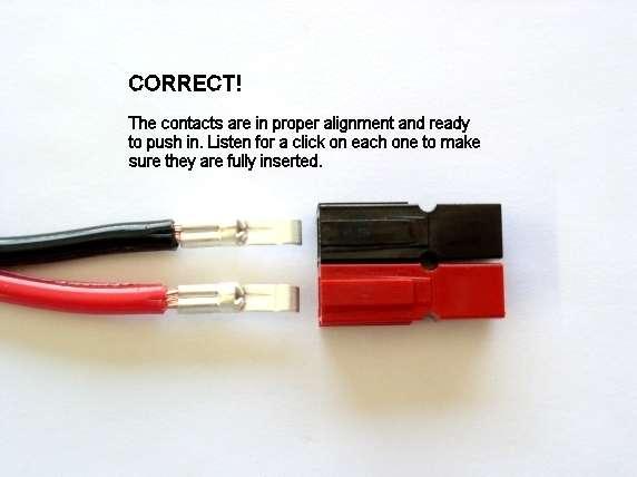
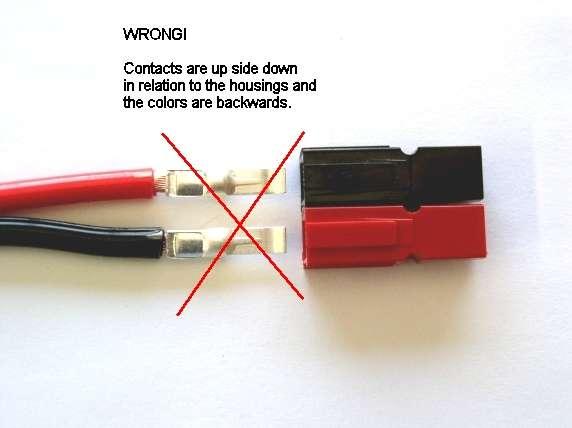
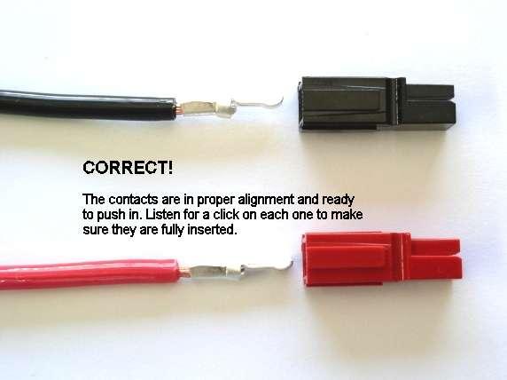
2 Put the connector housings together before putting the connector pins in, this is easier, especially when using heavy paired wire. Before soldering or crimping the contacts on to heavy paired wire, orient the contacts so that they are both facing the correct direction so that they go in the housings without twisting the wire. The plastic housings are held together with dovetail joints. Always slide these joints together! They will be damaged if you try to snap them together or apart. They ONLY slide together in one direction. This should be obvious by looking at them carefully. Powerwerx recommends the use of slotted retaining pins. Others do not like the possibility of them falling out in service. If your application is critical and that you want to make the pairing permanent you can use a cyanocrylic glue (Crazy Glue) to hold the connector bodies together. The contacts go in the housings in only one way. Insert the contacts with their sharp edge down against the flat spring that is in the housing. They should slide in and click. If you do not hear a click or they are not fully seated, fix them. When they are inserted fully you should notice that the contact and it's wire "floats" slightly inside it's housing. When looking in from the front of the housing the contact tip should slide over the top of the internal hosing spring. This is the clicking sound that you hear. Be careful when crimping. You may make the contact out of round and it will not slide into the contact easily. This may occur with different types of crimpers and various gauges of wire. To fix this situation you may have to rotate the contact 90 degrees from the original crimping orientation and recrimp either with the original crimper or a pair of pliers. In any case you need to make the barrel of the contact round again so it can slide in the housing.


3 YOU WILL NOT BE ABLE TO INSERT THE CONTACTS INTO THE HOUSINGS IF THEY ARE TOO WIDE AFTER SOLDERING OR CRIMPING!
4
5

6 Tug slightly on the assembled connector to make sure the contacts are locked in place. If you have trouble getting the contact to lock in to the housing you may have squashed the contact wider deformed it some how. Look at the side profile of the contacts before and after crimping, you may have to bend it back straight before inserting it in to the housing. When soldering the contact pins, be careful not to use too much solder. Keep the solder inside, where the wire goes. If a blob of solder gets on the outside of the connector body you may have trouble putting the contact into the housing. If you get solder on the contact surface area you will not make a good contact. When crimping the contact pins use a crimp that contains the wire completely inside the pin and doesn't spread the connector apart. A good crimp is one where the dimensions of the crimped portion are no more than an un-crimped pin. If the crimp is flattened out you will not be able to easily push the pin in to the body. If you bend the contact blade in relation to the crimp area you should straighten it before putting it in to the body. It is possibly to use larger or smaller gauge wire with the 30 and 45 amp connectors. The 30 amp contacts will work with difficulty with #10 wire if you cut the end cleanly and carefully put each and every strand of that wire in to the pin. It may be is easier to use 45 amp connectors on #10 wire. Using 16 gauge or smaller wire in a 30 amp contact requires that you double or triple up the wire to fill the crimp receptacle of the contact to get a good crimp.
7 A properly crimped contact should have a minimum hold on the wire of more than 25 pounds. A pair of connectors should snap together with 6 to 8 pounds force. Last but not least, MAKE SURE you have the polarity correct before plugging in your equipment. "Measure twice, cut once" as the saying goes.
Golf Trolley Workshop (Devon)
") Golf Trolley Workshop (Devon) Powerpole General Assembly Instructions Assemble the red and black plastic housings together correctly on the first try, they fit snugly and can be difficult to get apart.
Golf Trolley Workshop (Devon) Powerpole General Assembly Instructions Assemble the red and black plastic housings together correctly on the first try, they fit snugly and can be difficult to get apart.
Powerpole General Assembly Instructions
 Powerpole General Assembly Instructions The contacts go in the housings in only one way. Insert the contacts with their sharp edge down against the flat spring that is in the housing. They should slide
Power Poles. Interoperability -- Why Anderson Powerpoles??
 Interoperability -- Why Anderson Powerpoles?? Power Poles In the rather frantic and hectic long days and nights of amateur radio emergency operations in the immediate aftermath of the September 2001 World
POWERPOLE CONNECTORS. Fountain Valley RACES 05 Feb 2008
 POWERPOLE CONNECTORS Fountain Valley RACES 05 Feb 2008 ACCESORIES SPLITTER WITH OEM T-CONNECTOR ACCESSORIES RED DEE 2 SPLITTER Any connection point is an input / any connection point is an outlet ACCESSORIES
ARES PRESENTATION Anderson Powerpoles
 ARES PRESENTATION Anderson Powerpoles Steve Pituch EC, February 13, 2010 There is a very good reason for all ARES members to use Anderson Powerpoles on all their 12 Volt equipment including all radios,
Anderson Powerpoles. Powerpole Assembly. (PowerWerx Insructions)
") Anderson Powerpoles Powerpole Assembly (PowerWerx Insructions) Seaching for a Standard The old standard Molex 2-pin connectors could no longer hold up to the amp requirements of mobile and portable equipment
Anderson Powerpoles Powerpole Assembly (PowerWerx Insructions) Seaching for a Standard The old standard Molex 2-pin connectors could no longer hold up to the amp requirements of mobile and portable equipment
W7MRI's Anderson Powerpole. Power Hub
 W7MRI's Anderson Powerpole Power Hub This PDF is provided by K7JM at http://radio.mcdougallshome.net Don, W7MRI made up a nice small circuit board that holds 7 pairs of Anderson Powerpole connectors to
Assembly Instructions: Kit #5
 Assembly Instructions: Kit #5 1. Insert the T-pin into one of the caps. 2. Insert the rotor core into the same cap as shown below. Apply some pressure to push the rotor core approximately 1/2" (10-12 mm)
Bel Stewart Connector
 Page 1 of 8 PLUG ASSEMBLY INSTRUCTIONS FOR Cable with INDIVIDUALLY SHIELDED PAIRS (PIMF or SFTP) T568B Wiring Pattern For Cable with Overall Foil Shield (FTP), See Page 9 1 2 Cut cable to length. If you
Assembly Instructions for Power Drawer Series 35 amp and 75 amp
 Assembly Instructions for Power Drawer Series 35 amp and 75 amp These assembly instructions include the instructions for wire termination, contact insertion, contact removal, PCB mount, and panel mounting
Repairing Microsoft Wedge Touch Mouse Battery Cover Retaining Clip
 Repairing Microsoft Wedge Touch Mouse Battery Cover Retaining Clip Disassembly, repair and reassembly of Wedge Touch mouse when the battery cover will not stay closed. Also is a good guide to repair other
onlinecomponents.com
 Figure 1 PRO CRIMPER III Hand Crimping Tool Assembly 58603 1 consists of Die Assembly 58603 2 and PRO CRIMPER III Hand Tool Frame 354940 1. The die assembly consists of crimping dies and a locator assembly.
Read these instructions thoroughly before crimping any contacts.
 PRO CRIMPER III Hand Crimping Tool Assembly 58583 1 consists of Die Assembly 58583 2 and PRO CRIMPER III Hand Crimping Tool Frame 354940 1. The die assembly consists of crimping dies and a locator assembly.
Harmony Remote Repair
 Harmony Remote Repair harmonyremoterepair.com How to install your new Harmony One Front Cover/Touch Screen Important! Before you begin working on your Harmony One, you must discharge any static electricity
Jewelry Basics 101. Basic Wire Loops For best results, use both chain-nose and round-nose pliers. Method 2 Bend then cut. Method 1 Cut then bend
 Jewelry Basics 101 #68-007-01 Basic Wire Loops For best results, use both chain-nose and round-nose pliers. Method 2 Bend then cut Use non-serrated chain-nose pliers to bend the wire just above the bead.
1. Turn off or disconnect power to unit (machine). 2. Push IN the release bar on the quick change base plate. Locking latch will pivot downward.
. 2. Push IN the release bar on the quick change base plate. Locking latch will pivot downward.") Figure 1 Miniature Quick Change Applicators, of the end feed type, are designed to crimp end feed strip terminals to prestripped wires. Each applicator is set up to accept the strip form of certain specific
Figure 1 Miniature Quick Change Applicators, of the end feed type, are designed to crimp end feed strip terminals to prestripped wires. Each applicator is set up to accept the strip form of certain specific
LAGGING PIPES UP TO 125 mm IN DIAMETER WITH K-FLEX TUBING
 LAGGING PIPES UP TO 125 mm IN DIAMETER WITH K-FLEX TUBING Around 80% of piping used in civilian buildings can be insulated before fitting. This simplifies the task and saves time, taking advantage of the
Terminal Replacement Procedures
 HOW TO REPLACE CONNECTOR TERMINALS The terminal repair kits provide necessary tools and materials (terminals, wire seals, and splice connectors) to repair many damaged or faulty connector terminals. However,
The wick in your heater needs replacing if, after repeated cleanings, any of the following conditions still exist:
 WICK REPLACEMENT The wick in your heater needs replacing if, after repeated cleanings, any of the following conditions still exist: Slow to light, hard movement of the wick adjuster knob, kerosene odor
Hatchback Wing Riser Kit
 Hatchback Wing Riser Kit 2015-06-11 Thank you for purchasing this PERRIN product for your car! Installation of this product should only be performed by persons experienced with installation of aftermarket
Removing and Replacing the Y-truck
 Service Documentation Removing and Replacing the Y-truck To remove and replace the Y-truck you will need the following tools: 4mm Allen wrench 12mm stamped flat wrench #2 Phillips screwdriver (magnetic
STRENGTH Aligned teeth provide superior gripping power over standard vertical teeth. STRENGTH Diamond serrated jaws provide a firm grip
 STRENGTH Aligned teeth provide superior gripping power over standard vertical teeth STRENGTH Diamond serrated jaws provide a firm grip PLIERS AND SNIPS Locking Pliers Slip Joint Pliers Electrician s Pliers
HE Insert Series. Application Specification Apr 26 th, 2016 Rev. A. Table of contents
 HE Insert Series Table of contents 1. INTRODUCTION... 2 2. SUPPORTING DOCUMENTS... 2 2.1. Customer drawings... 2 2.2. Product specification... 2 2.3. Application Specification... 2 2.4. Standards... 2
Extraction Tool for Buss Contact
 Tooling Akey feature of the Cannon DL connector series is easy contact termination, both in the field and in high-volume production. An ergonomically designed hand crimp tool is available for the low volume
Miniature Circular Plastic Connector (CPC)
") Miniature Circular Plastic Connector (CPC) Application Specification 16 SEP 03 Rev O All numerical values are in metric units [with U.S. customary units in brackets]. Dimensions are in millimeters [and
Miniature Circular Plastic Connector (CPC) Application Specification 16 SEP 03 Rev O All numerical values are in metric units [with U.S. customary units in brackets]. Dimensions are in millimeters [and
PRO- CRIMPER* III Hand Crimping
 PRO- CRIMPER* III Hand Crimping Instruction Sheet Tool Assembly 58448-2 408-9357 With Die Assembly 58448-3 10 Mar 11 PROPER USE GUIDELINES Cumulative Trauma Disorders can result from the prolonged use
F-F-Fiddle Assembly Instructions
 F-F-Fiddle Assembly Instructions Bout Bridge Neck Machine Heads/Tuners Truss Rod Strings An open-source FFF 3d-printable electric violin. 1. Assemble materials 5 3 8 1 9,10, 11 7 4 2 6 PARTS 1. Bout part
Application Tooling Specification Sheet
 Modular Crimp Head Order No. 63811-5970 FEATURES Application Tooling Specification Sheet TYPE 4A Hand Crimp Tool Order No. 63811-5900 % A full cycle ratcheting hand tool ensures complete crimps % Ergonomically
Signal Mirror Installation Instructions
 Signal Mirror Installation Instructions 2005-2010 Chevy Corvette C6 THE safety accessory of the 21 st Century. P/N 210-0144-0 Rev. A3 (9/29/2011), BTV 2007 Muth Mirror Systems, LLC Page 3 of 10PplPage
Aurora,Ohio Fax:
 VPI VIDEO 1275 Danner Drive PRODUCTS Tel: 330-562-2622 www.vpi.us INCORPORATED Aurora,Ohio 44202 Fax: 330-562-1999 CRIMP-RJ45-SF 8 Contact Modular Crimp Tool For RJ45 Superflat Modular Plugs Introduction
BrewsBySmith.com STC DIY Kit
 BrewsBySmith.com STC-1000 + DIY Kit Contact Information: Greg Smith www.brewsbysmith.com greg@boostbysmith.com I. Hardware Included: STC-1000 flashed with latest software (v1.06 currently) (if purchased)
GORE Aerospace Ethernet Cables
 Termination Instructions The following procedures are based on Gore s best practices for terminating GORE Aerospace with the Carlisle Octax Connector System for both socket and plug versions. These procedures
Series 1500 Aluminum Door Canopy
 Series 500 Aluminum Door Canopy with Sidewings It is our recommendation that you read instructions carefully prior to assembly and installation. Series 500 with Sidewings mounting bar (A) top trim (B)
Application Tooling Specification Sheet
 Extractor Tool FEATURES Application Tooling Specification Sheet Order No. 63813-2700 This Extractor Tool is for the removal of Wire-to-Wire and Wire-to-Board terminal series in both plug and receptacles.
Home Electrical Wiring. Types of Receptacles and Wiring them for 120v 15Amp/20Amp
 Home Electrical Wiring Types of Receptacles and Wiring them for 120v 15Amp/20Amp Understanding the wires You have 3 wires in a home electrical system; Hot (Black wire) - dangerous one Neutral (White wire)
unit 3: GENErAL ElectriCAL SySTEM DiAGNOSiS
 Electrical/Electronic Systems unit 3: GENErAL ElectriCAL SySTEM DiAGNOSiS lesson 4: wire and connector repairs I. Connector repairs A. Connector repairs involve fixing damaged wires. Wires are marred due
GORE Aerospace Ethernet Cables
 Termination Instructions The following procedures are based on Gore s best practices for terminating GORE Aerospace with the Amphenol Oval Contact System (OCS) for both plug and receptacle versions. These
Series 1100 Aluminum Door Canopy
 Series 00 Aluminum Door Canopy with Support Arms It is our recommendation that you read instructions carefully prior to assembly and installation. Series 00 with Support Arms MOUNTING BAR (A) TOP TRIM
Spiderbeam Balun Construction Guide
 BALUN CONSTRUCTION GUIDE Ver. 1.0 1 The components of the Balun Kit are in a plastic bag. Most of the components are inside the plastic case of the balun. The aluminum U-profile and the RG-142 Teflon Coax
Poke-Home: Horizontal AWG: WTB INTER CONNECT APPLICATIONS FEATURES AND BENEFITS ELECTRICAL MECHANICAL ENVIRONMENTAL HOW TO ORDER 00X
 The new 9276 series connector provides a quick and reliable wire-toboard termination in a sleek 2.5mm pitch SMT package for a broad range of industrial and commercial markets. With almost every product
Assembly Procedures for 96-Position GPEC II and III Sealed Connector System (Harness)
") Assembly Procedures for 96-Position GPEC II and III Sealed Connector System (Harness) Instruction Sheet 408-10229 08 SEP 17 Rev E Wire Dress Assembly (Straight Version) Plug Housing Assembly Optional Blink
Assembly Procedures for 96-Position GPEC II and III Sealed Connector System (Harness) Instruction Sheet 408-10229 08 SEP 17 Rev E Wire Dress Assembly (Straight Version) Plug Housing Assembly Optional Blink
Crimping Instructions
 Fischer Connectors SA SaintPrex, Switzerland Phone +41 21 00 9 9 Fax +41 21 00 39 24 www.fischerconnectors.com mail@fischerconnectors.ch Crimping Instructions Assembly Instructions CONTENTS Page Scope
Handling Precaution for Terminal and Connector
 1 Handling Precaution for Terminal and Connector Handling Precaution for Terminal and Connector This manual is to describe basic precautions for use of terminal and connector in the following. Make use
MacBook Power Cord 5-Pin MagSafe Connector and Cable Replacement
 MacBook Power Cord 5-Pin MagSafe Connector and Cable Replacement If the cord connecting the power brick to your MacBook is damaged, use this guide to replace it. Written By: Pierre Merineau ifixit CC BY-NC-SA
Xkitz.com XLO-5CP Control Panel for Five Channel Color Light Organ
 Xkitz.com XLO-5CP Control Panel for Five Channel Color Light Organ Rev 1.15 An Optional accessory for the Xkitz XLO-5 or XLO-5DC 5 Channel Color Light Organs Introduction This kit contains all the electronics
MX150L tm INDUSTRIAL SEALED CONNECTOR SYSTEM
 MX150L tm INDUSTRIAL SEALED CONNECTOR SYSTEM The MX150L Industrial Sealed Connector System is IP67 rated and conforms to UL 1977, but it is NOT suitable for automotive applications with requirements such
Assembly Instructions for B7971 Smart Socket
 Assembly Instructions for B7971 Smart Socket Identification and installation of the resistors, Fig1 Segment 1,R1, 22k Segment 4, R4, 22k Segment 2, R2, 27k Segment 3, R3, 27k Segment 5, R5, 27k Segment
Powerpole Connectors - PP75: up to 120 Amps
 Powerpole Connectors - PP75: up to 120 Amps PP75 with Mounting Wings PP75 series Powerpole housings can be used for wire-to-wire, wire-to-board, and wire-to-busbar applications. Wire sizes from #16 AWG
Replacing Hammer Butt Springs in the Upright Action
 Schaff Piano Supply Company Presents: Replacing Hammer Butt Springs in the Upright Action Basic Procedures By Chuck Behm Replacing Hammer Butt Springs -Rationale- In the restoration of an upright, the
AMPSEAL* Automotive Plug Connector and Header Assembly
 AMPSEAL* Automotive Plug Connector and Header Assembly Application Specification 114-16016 17 APR 14 NOTE NOTE i All numerical values are in metric units [with U.S. customary units in brackets]. Unless
Crimping Instructions
 Fischer Connectors SA SaintPrex, Switzerland Phone +41 21 800 95 95 Fax +41 21 800 39 24 www.fischerconnectors.com mail@fischerconnectors.ch Crimping Instructions Assembly Instructions CONTENTS Page Section
How to Insert a Tuck or Push Lock Closure
 Published on Sew4Home How to Insert a Tuck or Push Lock Closure Editor: Liz Johnson Friday, 15 August 2014 1:00 We've all seen this popular little clasp. It's the go-to closure on everything from casual
High Current Pin and Socket Contacts 31 JUL 13 Rev C
 Application Specification High Current Pin and Socket Contacts 31 JUL 13 NOTE NOTE i All numerical values are in metric units [with U.S. customary units in brackets]. Dimensions are in millimeters [and
A socket contact support (supplied separately) must be installed onto the locator assembly.
 must be installed onto the locator assembly.") Figure 1 PRO CRIMPER III Hand Tool Assembly 1976444 1 consists of PRO CRIMPER III Hand Tool Frame 354940 1 and Die Assembly 1976444 2. The tool assembly is used to crimp the contacts listed in Figure 1.
Figure 1 PRO CRIMPER III Hand Tool Assembly 1976444 1 consists of PRO CRIMPER III Hand Tool Frame 354940 1 and Die Assembly 1976444 2. The tool assembly is used to crimp the contacts listed in Figure 1.
ENGR 40M Project 2a: Useless box
 ENGR 40M Project 2a: Useless box Prelab due 24 hours before your section, April 16 19, 2018 Lab due before your section, April 24 27, 2018 1 Objectives In this lab, you ll assemble a useless box like the
Assembly Instructions for the 1.5 Watt Amplifier Kit
 Assembly Instructions for the 1.5 Watt Amplifier Kit 1.) All of the small parts are attached to a sheet of paper indicating both their value and id. 2.) Leave the parts affixed to the paper until you are
LUX INSTALLATION GUIDE. LUX Panel V Groove Installation. Installation Guide. February
 LUX Panel V Groove Installation Installation Guide February 2017 www.luxpanel.ca LUX Panel V Groove Installation LUX panel steel cladding is designed to be installed vertically, horizontally, diagonally
01. Parts. Blink v1.1. Battery Holder x1. Red LED x1 Green LED x1 Blue LED x1. Resistors x3. Battery x1. Blink PCB x1. Push Button Switchers x3
 Blink L1 L2 L3 01. Parts Battery Holder x1 Red LED x1 Green LED x1 Blue LED x1 Resistors x3 Learn to Solder Kit Battery x1 L1 L2 L3 Blink PCB x1 S3 Push Button Switchers x3 02. Tools RECOMENDED Soldering
GT3B Hack Kit Install Instructions Written By Austin Hutchison
 GT3B Hack Kit Install Instructions Written By Austin Hutchison Step 1: Remove 4 screws located on top of the radio. 1 Step 2: There are small plastic latches that also hold the top in place. The easiest
Powerpole Connectors - PP75: up to 120 Amps
 Powerpole Connectors - PP75: up to 120 Amps PP75 with Mounting Wings PP75 series Powerpole housings can be used for wire-to-wire, wire-to-board, and wire-to-busbar applications. Wire sizes from #16 AWG
Catch The Bug. Body Build. Where are we? Process # You are. here.
 Catch The Bug Body Build Process # 1 Where are we? 1) Body Build- The mechanical part of the bug is constructed. 2) Electronics Lab- Bug Experiments teach the fundementals of electronics. 3) Final Wiring-
CRIMP VS. SOLDER: PROS & CONS
 CRIMP VS. SOLDER: PROS & CONS Connections More Vital Than Ever Today, a flawed coaxial connection can severely reduce performance on digital systems like ThinNET (EtherNET), Wireless networks like WiFi
Instruction Sheet Tool Kit [ ] (for SL Series 110 Jack Connectors)
![Instruction Sheet Tool Kit [ ] (for SL Series 110 Jack Connectors)](/thumbs/74/70133560.jpg "Instruction Sheet Tool Kit [ ] (for SL Series 110 Jack Connectors)") Instruction Sheet Tool Kit 1725150 [ ] (for SL Series 110 Jack Connectors) 26 FEB 04 PROPER USE GUIDELINES Cumulative Trauma Disorders can result from the prolonged use of manually powered hand tools.
Instruction Sheet Tool Kit 1725150 [ ] (for SL Series 110 Jack Connectors) 26 FEB 04 PROPER USE GUIDELINES Cumulative Trauma Disorders can result from the prolonged use of manually powered hand tools.
SBE 160 / SBX 175 ORDERING INFORMATION SECTION 3. Touch Safe Interface Minimizes potential contact with live circuits per IEC & IEC 60529
 Connectors - up to 175 Amps SBX and SBE connectors can integrate up to 8 auxiliary power / signal contacts along with the two primary power circuits. SBE connectors feature an IEC 60950 touch safe housing
AAG CloudWatcher Update Humidity sensor (*)
") AAG CloudWatcher Update Humidity sensor (*) (*) For AAG CloudWatcher units SN 400 onwards. For a better understanding of these instructions we have divided them into two sections: to units with serial
AAG CloudWatcher Update Humidity sensor (*) (*) For AAG CloudWatcher units SN 400 onwards. For a better understanding of these instructions we have divided them into two sections: to units with serial
Repairing your Porsche 928 Central Warning System (CWS) controller
 controller") Repairing your Porsche 928 Central Warning System (CWS) controller Disclaimer: This procedure is for a 1984 Porsche 928 S controller. Overview: Under the left foot pedal (dead pedal) of the Porsche 928
Repairing your Porsche 928 Central Warning System (CWS) controller Disclaimer: This procedure is for a 1984 Porsche 928 S controller. Overview: Under the left foot pedal (dead pedal) of the Porsche 928
Installation Instructions Road King Classic Saddlebag Bezels
 Installation Instructions Road King Classic Saddlebag Bezels Thank you for your purchase of Bagger Audio Road King Classic Saddlebag Bezels for your Harley-Davidson motorcycle. We have carefully engineered
Termination of D-621 Triaxial Connectors to Shielded Twisted Pair Cable for MIL-STD-1553B Applications
 1 of 18 Termination of D-621 Triaxial Connectors to Shielded Twisted Pair Cable for MIL-STD-1553B Applications This Engineering Standard forms a part of Engineering Standard ES-61162: "D-621 Connectors
Application Specification
 1 of 10 A 1.0 OBJECTIVE This specification provides information and requirements regarding customer application of Minitek Pwr4.2 crimp to wire connectors. This specification is intended to provide general
DO NOT PULL ON THE SHEATH.
 Removing and Replacing the Head Cover To remove and replace the head cover you will need the following tools: #2 Phillips screwdriver (magnetic tip preferred) Removing the Head Cover 1. Ready the machine
THE RING RESONATOR (K-975)
") THE RING RESONATOR (K-975) OUTPUT BOOST The Ring Resonator An Octave Up Fuzz Modkitsdiy.com 9 VDC CENTER (-) ADAPTER TO AMP IN FROM GUITAR OUT Unplug when not in use to save battery life. Use these instructions
THE RING RESONATOR (K-975) OUTPUT BOOST The Ring Resonator An Octave Up Fuzz Modkitsdiy.com 9 VDC CENTER (-) ADAPTER TO AMP IN FROM GUITAR OUT Unplug when not in use to save battery life. Use these instructions
Connectors for Ribbon Flex and Soldering Tips
 Connectors for Ribbon Flex and Soldering Tips 11235 West Bernardo Court, Suite 102 San Diego, CA 92127 888-880-1880 Fax: 707-281-0567 EnvironmentalLights.com Instructions for Connecting Power or Control
LDB-1 Kit Instructions Page 1 of 8
 LDB-1 Kit Instructions Page 1 of 8 Important Information Congratulations and thank you for your purchase of the LDB-1 Little Drummer Boy Analog Drum Machine Kit! Before you start, please read the enclosed
Service Bulletin Terminal Replacement Instructions (Replaces , dated May 2, 1995) December 18, 2000 ALL
 December 18, 2000 ALL") Service Bulletin 00-039 Applies To: ALL December 18, 2000 Terminal Replacement Instructions (Replaces 95-007, dated May 2, 1995) These terminal replacement instructions apply to these kits and tools: Terminal
Service Bulletin 00-039 Applies To: ALL December 18, 2000 Terminal Replacement Instructions (Replaces 95-007, dated May 2, 1995) These terminal replacement instructions apply to these kits and tools: Terminal
Installation Instructions. Oakmont Folding Doors
 Before You Start For quick and easy installation of your Oakmont folding door, read these instructions thoroughly. A few minutes of prior planning will make the job easier and ensure years of trouble-free
Powerpole Connectors - PP75: up to 120 Amps
 Powerpole Connectors - PP75: up to 120 Amps PP75 with Mounting Wings PP75 series Powerpole housings can be used for wire-to-wire, wire-to-board, and wire-to-busbar applications. Wire sizes from #16 AWG
Instructions for Lighting an S Scale Caboose
 Instructions for Lighting an S Scale Caboose The S Scale Caboose lighting kit is adaptable for most caboose models of rolling stock including American Flyer (TM) and contains the same components as found
BIFOLD FUTON FRAME TRINITY ARM. Seat Rails and Slats x 1. *Note: Use 4pc of 100mm Bolts and 4pc of 60mm Bolts to attach the arms to the Stretchers.
 1A Parts in this box. 2pc with extra holes 2pc with extra holes & plastic stoppers Arms x 2 Back Rails and Slats x 1 Full Size: Slat Supports x 6 3pc are longer for the Back deck Back Side Rails x 2 Seat
COMMERCIAL PORTABLE CRIMP TOOLING
 COMMERCIAL PORTABLE CRIMP TOOLING A FLEXIBLE APPROACH TO PORTABLE CRIMPING INTRODUCTION TO TOOLING SOLUTIONS TE Connectivity. A Leader in Crimp Quality. Anyone can make a tool to crimp terminals onto a
40 & 50 Foot PS-1 Box Car Assembly Instructions
 40 & 50 Foot PS-1 Box Car Instructions Push the #2100 coupler/stirrup assembly onto the ends of the metal floor. Slide them into the slots and slightly lift the ends (wings), then press firmly on the front
Hand Crimp Tool Specification Sheet Order No
 Hand Crimp Tool Specification Sheet Order No. 63811-2600 FEATURES TYPE 4A % A full cycle ratcheting hand tool ensures complete crimps % Ergonomically designed soft handles % Precisely designed crimping
Connectors for Strip and Soldering Tips
 Connectors for Strip and Soldering Tips Instructions for Connecting Power or Control Signals to 12 or 24 Volt DC LED Strip 11235 West Bernardo Court, Suite 102 San Diego, CA 92127 888-880-1880 Fax: 707-281-0567
Line-Following Robot
 1 Line-Following Robot Printed Circuit Board Assembly Jeffrey La Favre October 5, 2014 After you have learned to solder, you are ready to start the assembly of your robot. The assembly will be divided
METRI-PACK 2016 FEATURE PRODUCT JUL. Sealed Connector Systems OF THE MONTH. Weather-Pack And Deutsch Connector. tifcoonline.
 JUL METRI-PACK 2016 Weather-Pack And Deutsch Sealed Systems FEATURE PRODUCT OF THE MONTH www.tifco.com tifcoonline.com Phone: 800.868.4326 Fax: 800.535.4619 tifco@tifco.com Main Office: Houston, TX Branch
THE AGGRESSOR (K-995)
") THE AGGRESSOR (K-99) TONE VOLUME DISTORTION MID-SHIFT SWITCH LED The Aggressor Distortion Pedal Modkitsdiy.com 9 VDC CENTER (-) ADAPTER TO AMP IN FROM GUITAR OUT Unplug when not in use to save battery
THE AGGRESSOR (K-99) TONE VOLUME DISTORTION MID-SHIFT SWITCH LED The Aggressor Distortion Pedal Modkitsdiy.com 9 VDC CENTER (-) ADAPTER TO AMP IN FROM GUITAR OUT Unplug when not in use to save battery
Wiring our Micro LEDs CAUTION!
 Wiring our Micro LEDs Secure Site Shop with Confidence Best viewed using: Internet Explorer or Mozilla Firefox If you've wired up some of our 2x3 LEDs, you've gained the general techniques required to
Terminating D /-0289 Subminiature SolderTact Contacts to Twisted-Pair Cable
 Print 12-Jun-03 1 of 11 Terminating D-602-0288/-0289 Subminiature SolderTact Contacts to Twisted-Pair Cable 1. Purpose and Scope This engineering standard contains the termination procedures, inspection
Assembling Instruction. S418 PV Connector M16 Cable Mount
 Assembling Instruction S418 PV Connector M16 Cable Mount Electrical Rating: 1000V DC 30A Max. Operation Temperature Range: -40~+90 degree C Caution: 1. Connectors are to be used only to interconnect firmly
Bi-Color Signal Mirror Installation Instructions
 Bi-Color Signal Mirror Installation Instructions 2005-2009 Toyota Tacoma THE safety accessory of the 21 st Century. P/N 210-0141-0 Rev. A2 (3/30/09), BTV 2007 Muth Mirror Systems, LLC Page 3 of 13PplPage
Application Tooling Specification Sheet
 HAND CRIMP TOOL FEATURES Application Tooling Specification Sheet TYPE 4D Order No. 63827-1400 A full cycle ratcheting hand tool ensures complete crimps Ergonomic soft grip handles for comfortable crimping
Lindab Safe and Lindab Safe Click
 Mounting instruction and Click Type-approved ducts and fittings and The and the duct system are type-approved, as per certificate no. 1358/88 issued by SITAC and are subject to continuous production checks.
Application Tooling Specification Sheet
 Hand Crimp Tool Application Tooling Specification Sheet TYPE 4D Order No. 63819-1300 FEATURES A full cycle ratcheting hand tool ensures complete crimps Ergonomic soft grip handles for comfortable crimping
Stac64 Unsealed Connector System
 Unsealed Connector System 2.54mm (.100") Pitch 34729 Female 22.70 x 22.23 Features and Benefits Pre-assembled TPA to receptacle housing shipped as single assembly provide applied labor and cost savings
INSTRUCTION BOOK EASILY REMOVEABLE DIES FOR YOUR BINDING NEEDS OD 4012 SHOWN WITH THE OPTIONAL PALM SWITCH FOR THE OD 4012
 RHIN- -TUFF INSTRUCTION BOOK FOR THE OD 4012 AND INTRODUCTION TO THE OD 4012 BINDING MODULES www.rhin-o-tuff.com HD 4270 OD 4300 HD 4470 HD 4171 HD 8370 PAL 14 HD 4170 PAL 14 EASILY REMOVEABLE DIES FOR
1.0 Receiver TAC Contact Insertion/Extraction. 2.0 TAC (Receiver) Module Installation/Removal. 3.0 Wiring Contact Insertion/Extraction
 Module Installation/Removal. 3.0 Wiring Contact Insertion/Extraction") Downloadable Documents (Adobe Acrobat (TM) format) Click on the links below to view or download copies of VPC User Manual in Adobe Acrobat (.PDF) format. Note: If you would like printed copies of any of
Downloadable Documents (Adobe Acrobat (TM) format) Click on the links below to view or download copies of VPC User Manual in Adobe Acrobat (.PDF) format. Note: If you would like printed copies of any of
KN-8828B Upgrade Directions
 KN-8828B Upgrade Directions This document outlines the steps to take to update earlier Hottop Bean Roasters to the KN-8828B 2007 by Chang Yue and Hottop USA - All Rights Reserved No part of this document
SBE 320 / SBX 350 Connectors - up to 350 Amps
 Connectors - up to 350 Amps ORDERING INFORMATION SBX and SBE connectors can integrate up to 8 auxiliary power / signal contacts along with the two primary power circuits. Sequencing within auxiliary positions
1503 Follow Spot Yoke, Source Four LED
 1503 Follow Spot Yoke, Source Four LED Rev 1.0 2016 City Theatrical, Inc. Getting Started with the City Theatrical Follow Spot Yoke for source four LED Congratulations on the purchase of your City Theatrical
Standard Kit #1 (5-way switch)
") Standard Kit #1 (5-way switch) Please Read All Instructions Before Beginning. Tools you will need: Soldering Iron (35 watt preferably) Solder Wet Sponge Wire Clippers 3/8 Drill Bit 1/4 Drill Bit Variable
Standard Kit #1 (5-way switch) Please Read All Instructions Before Beginning. Tools you will need: Soldering Iron (35 watt preferably) Solder Wet Sponge Wire Clippers 3/8 Drill Bit 1/4 Drill Bit Variable
OpenROV. Guide 3 - Electronics. We will now move to the assembly of the electronics that will control the ROV. Written By: OpenROV
 OpenROV Guide 3 - Electronics We will now move to the assembly of the electronics that will control the ROV. Written By: OpenROV 2017 openrov.dozuki.com Page 1 of 33 INTRODUCTION We will introduce soldering