Bob's Card Models
|
|
|
- Marvin Chandler
- 6 years ago
- Views:
Transcription

1 Bob's Card Models My Mars Martin water bomber, compared with the same-scale 'Tracker' (both 1:72) Martin Mars water bomber (1:72). The Martin Mars were the largest flying boats ever to enter production, and the two surviving tankers are now operated by the Coulson Group, based at Sproat Lake near Port Alberni, British Columbia. They can carry up to 30,000 litres of water and are used to fight fires along the coast of British Columbia, and even sometimes in the interior Building Instructions Print all sheets on 210 to 230 g card, except sheet Paper, Sheet 20. When gluing card parts at right-angles to another piece (eg bulkheads to the outer skin), holding together with fingers until dry usually results in the 'skeleton' image of the bulkheads - not nice! Hold together with 2 flat pieces of wood or plastic. NOTE: Insert the bulkheads using a cocktail stick or tooth-pick (or even better, I use a long screw) pushed into a tight hole in the centre of each bulkhead. The fit of the bulkhead must be flush and not tight, otherwise ugly "ribbing" will be visible on the fuselage. Should the bulkheads be a tiny bit too large to place in the positions marked, snip off the relevant amount. Green areas must be cut out, BUT usually after gluing any folds. This is NOT an easy project, and critical input of the builder is required at each stage. Being a large model, it must be expected that minor alterations have to be made here and there, Very minor errors in cut or in angles, will result in slight adaptations having to be made at some stage. The problem of potential "ribbing" occurs particularly often in this model, and when gluing for example bulkheads, holding the bulkheads in position until the glue is dry, must be done with flat pieces of wood/plastic etc, rather than with fingers. Fuselage 1
2 1. Cut out bulkheads A to F, make 3x thick by gluing on waste card. 2. Cut out the fuselage parts [1] - [5], round each of the 5. Note the positions of the b'heads (arrowed on sheet). 3. As the middle of each long tab of the fuselage parts is also the V-portion of the fuselage, it must firstly be sharply folded length-wise to give a flexible middle, then flattened before closing/gluing each fuselage part. 4. Also, each fuselage part must also exhibit these sharp folds - bend sharply along the lines marked. 5. Also before closing/gluing, the hull must also be roughly formed by rolling each hull side around a 15-20mm round rod. Use the b'heads to judge the approximate rounding. 6. Close form [3], gluing the tab. Insert bulkhead B and glue in place, initially not gluing the V-portion. When dry, glue the V-portion, using a round rod to get the form correct. 7. Close the form [4] glue its tab. Insert b'head C and glue in place. When dry, glue the V-portion. Glue [4] to [3]. 8. Close the form [5] glue its tab. Insert b'head D and glue in place. When dry, glue the V-portion. Glue [5] to [4]. Insert b'head E and glue in place. 9. This is quite difficult - part [6] rises to the tail with a curve, and not a straight line... cut out [6] and its tab (note that its 2 sides are not straight, but slightly curved). 10. Part [6]: bend the short grey lines, for the profile to match that of [5]. 11. If you place the 2 sides to be joined on a curved surface, you will see that they match Glue/close the form. 13. Glue onto [5]. Add b'head F. 14. Add parts [7] and [8]. NB: When parts [6], [7] and [8] are glued in place, the line along their tops must be straight to accommodate the rear fin assembly Cockpit & nose 15. Cut out [2], cut out all slits, fold the 2 folds giving the V-shape to the hull. 16. Bend down the 3 tabs under each front window. 17. To give curvature to the cockpit, bend down the flaps containing the 3 front windows, as well as the 2 sides of the cockpit. 18. Cut out and bend the tab along its length. Glue to both sides of the hull thus closing the form. 19. Using a 10-20mm diameter rod, round the 2 sides of the hull, to match the rounding of bulkhead B. 20. Glue the left and right front window flaps to their respective sides, using the tiny tabs (optimise the curvature by cutting tiny slits in the tab). Finally, glue the left and right front windows to the central window. 21. Glue [2] onto [3]. 22. Cut out nose [1]. Carefully round form with an approx 10mm bar. Cut out and glue tab onto one side only, after again folding it length-wise to give the V-form. Do not yet close the form. 23. Glue each of the pointed segments to its neighbour, then close/glue the form. 24. Make a fold in the 2 marked positions to give the V-profile. 25. Push in b'head A and glue in place. 26. If the tip of the nose is too pointed, cut point 1mm back, 'wetten' with glue, and push back with fingers. 27. Glue nose onto [2]. If necessary, make a 5-10mm long snip in the top of the cockpit, glue under the snips and smooth down. Rear Fin & Wings 28. Cut out the fin [9], its horizontal strut [10] and the base of the fin [11]. 29. Bend the main tab and the serrated tabs, fold in half along the leading edge, close/glue the fin. 30. Cut out the 2 sides of the fin base [11], bend the serrated tabs, and glue the 2 parts together. 31. Insert the horizontal strut [10] on a tooth-pick, into the fin and glue in place, not flush but about 5mm inside the fin Insert the glued (white portion) fin through the base [11], pull through so that the red colour of the fin just protrudes. 33. Cut out the green slit on the base - the Wing strut will be inserted here. 34. Cut out the wing strut [13], glue 3x on card to make 4x thick. 35. Insert the wing strut half-way into one of the wings, along the aileron marking and glue. 36. Push the wing strut through the slit in the fin base of the fin, put a bead of glue along the edges of the protruding wing strut, push the other wing over and hold until dry. 37. Cut out the 4 green slits on the top of the fuselage, glue the 4 tabs of the fin/wing assembly, and push in place. 38. Glue along all joins with a bead of glue. Wings 2
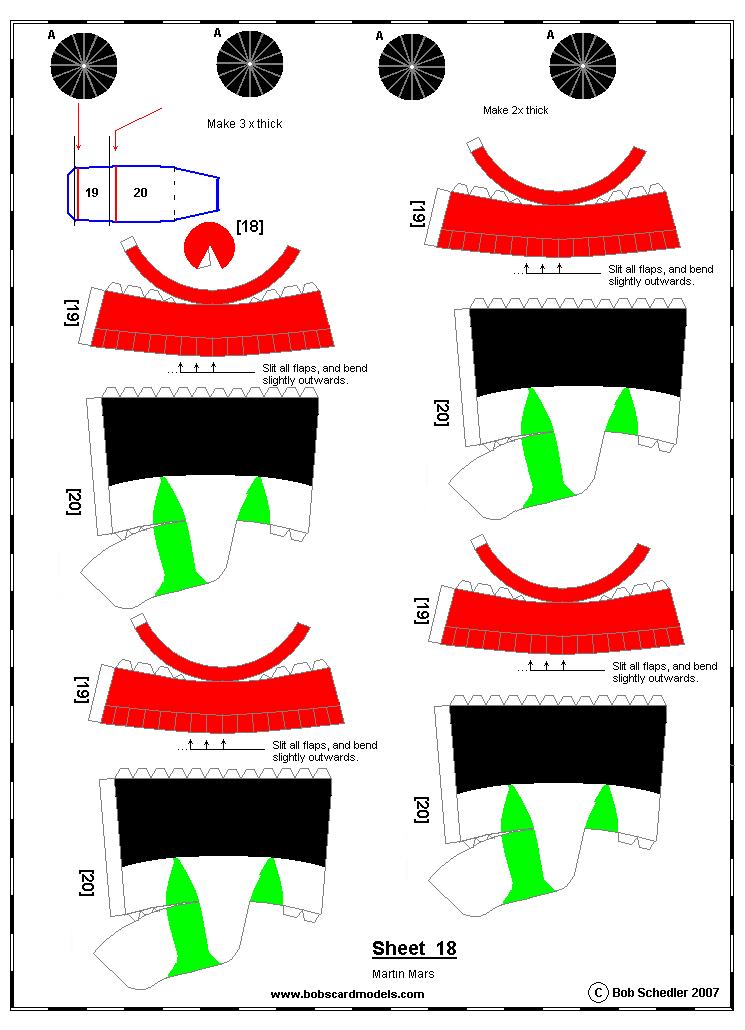
3 39. Cut out the Wing portions [14aR], [14bR] and [14cR], as well as the float supports [15R]. Cut out the 2 green curved slits on [14aR] and [14bR], which are the fixing points of the floats. Fold tabs and glue. Slip [14cR] through [14bR] with the tab glued. Likewise the latter through [14aR], in eavh case making sure that the leading edge is a straight line. 40. Repeat for the left-hand wings. 41. Cut out, fold and glue the 2 wing stabilisers [17]. Join the 2 together with the connector [18]. 42. Insert the 70-80cm stabiliser into each wing, previously wetting both sides of the stabiliser with glue. 43. Cut out the floats [16] and their supports [15], fold, pierce a tiny hole in the 2 green slits (do not yet cut out the whole slit), and glue the floats to their closed forms, then cut the slits (2 in each float). 44. Close/glue the main tab of each support. The 2 tabs at the base of the support are inserted/glued into one of the slits on the float, the second support likewise, into the neighbouring slit. During the drying period of the glue, the top of the supports should be about 5 cm from each other, to get the correct angle of the supports prior to fitting them into the slits under each wing. 45. Fit/glue float assembly onto the underside of each wing. 46. Cut along the green lines on the top of fuselage part [4] and bend the flaps outwards. Glue the whole wing assembly onto this 'platform.' Very tricky as you must make sure that all angles are correct. Use long elastic bands over the wings until glue is dry. Engines 47. For each motor, cut out parts [19] to [20], as well as motor disc A. 48. Round and close/glue [19]. 49. Round and close/glue main tab of [20]. Close/glue end of [20]. Cut out all green areas. On front end, glue on motor disc A, and put glue around the circumference of A. Insert the unit inside [19] as far as it will go. 50. Slit all the flaps on [19], and bend each flap slightly outwards. 51. Cut out the Air Inlet Ducts [20A] for each engine, fold, glue, cut out and glue in position as marked on the sheet. 52. Cut out the 4 4-bladed propellers [21], fold, glue, then glue on the tip of a tooth-pick or pin. Cut out and add the nose cones [22]. Afix. Accessories 53. Cut out aerial [23], fold, glue in position on marking on top of cockpit. ---ooooooo--- 3
4
5

6

7

8
9

10

11

12

13
14

15

16
17

18
19
20
21
22
23
Bob's Card Models and [Resources]
![Bob's Card Models and [Resources]](/thumbs/90/104319506.jpg "Bob's Card Models and [Resources]") Bob's Card Models www.bobscardmodels.altervista.org and www.zealot.com [Resources] Douglas DC-6B 1:72 DC-6 planes were often converted to forest fire-fighting duties, and the 'Securité Civile' based at
Bob's Card Models www.bobscardmodels.altervista.org and www.zealot.com [Resources] Douglas DC-6B 1:72 DC-6 planes were often converted to forest fire-fighting duties, and the 'Securité Civile' based at
Bob's Card Models and [Resources]
![Bob's Card Models and [Resources]](/thumbs/94/120604139.jpg "Bob's Card Models and [Resources]") Bob's Card Models www.bobscardmodels.altervista.org and www.zealot.com [Resources] Short 330-200 (Scale 1:72) The Short 330-200 is a short haul airlcraft produced by Short Brothers in the UK. The aircraft
Bob's Card Models www.bobscardmodels.altervista.org and www.zealot.com [Resources] Short 330-200 (Scale 1:72) The Short 330-200 is a short haul airlcraft produced by Short Brothers in the UK. The aircraft
Bob's Card Model
 Bob's Card Model www.bobscardmodels Conair C S 2F (Tracker) water-bomber(1:72) Securité Civile's converted Tracker, used for patrol duty, but also for water-bombing (3200 litres). Together with the Canadairs
BOBS CARD MODELS. De Haviland Dash-8 water-bomber (1:72)
") BOBS CARD MODELS www.bobscardmodels.com De Haviland Dash-8 water-bomber (1:72) A Canada de Haviland Dash-8 fitted with a large water tank, complements the French aerial firefighters' fleet of Canadairs
BOBS CARD MODELS www.bobscardmodels.com De Haviland Dash-8 water-bomber (1:72) A Canada de Haviland Dash-8 fitted with a large water tank, complements the French aerial firefighters' fleet of Canadairs
Bob's Card Models and [Resources]
![Bob's Card Models and [Resources]](/thumbs/81/83816834.jpg "Bob's Card Models and [Resources]") Bob's Card Models www.bobscardmodels.altervista.org and www.zealot.com [Resources] Grumman Albatross HU-16E 1:72 The Grumman HU-16 Albatross is a large twin-radial engine amphibious flying boat. Originally
Bob's Card Models www.bobscardmodels.altervista.org and www.zealot.com [Resources] Grumman Albatross HU-16E 1:72 The Grumman HU-16 Albatross is a large twin-radial engine amphibious flying boat. Originally
Bobs Card Models
 Bobs Card Models www.bobscardmodels.com Canadair CL-415 (1:72) The Bombardier 415 (formerly Canadair CL-415) is a Canadian amphibious aircraft purpose-built as a water bomber. It is the only aircraft designed
BOBS CARD MODELS. Canadair CL-215 (1:72)
") BOBS CARD MODELS www.bobscardmodels.com Canadair CL-215 (1:72) Canadair was a civil and military aircraft manufacturer in Canada. It was the subsidiary of other aircraft manufacturers and a nationalized
BOBS CARD MODELS www.bobscardmodels.com Canadair CL-215 (1:72) Canadair was a civil and military aircraft manufacturer in Canada. It was the subsidiary of other aircraft manufacturers and a nationalized
C-180 Builder s Manual
 C-180 Builder s Manual. May 20, 2002 Last revised July 11, 2002 Copyright! 2002 Douglas Binder, Mountain Models www.mountainmodels.com sales@mountainmodels.com (719) 630-3186 1 Required Equipment! Xacto
TIGER MOTH 120 ASSEMBLY INSTRUCTIONS
 TIGER MOTH 120 ASSEMBLY INSTRUCTIONS SPECIFICATIONS Wing Span: Length: Radio: Flying Weight: 1920mm 1580mm 4 channel with 6 servos 4200g AILERON ASSEMBLY 1 Start by removing the servo cover from the bottom
SASKATOON, Saskatchewan
 CONSTRUCTION GUIDE AVRO ARROW (CONTEST VERSION) Copyright, Bill Jones, 2004 SASKATOON, Saskatchewan This is a work in progress, so there are a couple of rough areas ( I ll point out those that I m aware
Instruction Manual: Ariane V (Hermes Space Shuttle)
") 56. A science pod will be folded to create a rectangular prizm to be glued at the rear. 59. These two parts make up the main fuselage of the Hermes space shuttle. 57. As you can see, the science pod will
56. A science pod will be folded to create a rectangular prizm to be glued at the rear. 59. These two parts make up the main fuselage of the Hermes space shuttle. 57. As you can see, the science pod will
E-AERO EPP PITTS KIT From BP HOBBIES. Parts Included in kit
 E-AERO EPP PITTS KIT From BP HOBBIES Parts Included in kit Thank you for purchasing the BP Hobbies/E-aero EPP Pitts. Please take the time to read through the instruction manual before beginning the build.
Walt Disney's RM-1 Lunar Reconnaissance Craft
 Walt Disney's RM-1 Lunar Reconnaissance Craft The RM-1 Lunar Reconnaissance Craft was the first spacecraft designed to be built in orbit with modular components, specifically jettisoned pieces of the "Man
RESolution V2 Manual
 RESolution V2 Manual Note for the German Manual: Yellow Bottle thick CA Pink Bottle Med CA Blue tube 5 minute Epoxy Green tube 90 Minute Epoxy Construction of the Fuselage Step 1: Cover the plan with a
The Papernator 2003 created and designed by Clive Davis, NAR #80412
 The Papernator 2003 created and designed by Clive Davis, NAR #80412 CG with motor loaded= 3.75 (9.6 cm) from base nose weight = 1/2 oz or 15 grams body tube nose cone shock cord mount fins (4 qty) launch
WRIGHT FLYER 1 INSTRUCTIONS FOR THE D10LC KIT
 WRIGHT FLYER 1 INSTRUCTIONS FOR THE D10LC KIT Manufactured in the USA by Easy Built Models PO Box 681744, Prattville, AL 36068-1744 Visit us at www.easybuiltmodels.com Easy Built Models GLUE METHODS Always
S.E.5a (Build Instructions)
") S.E.5a (Build Instructions) Specifications Wingspan: 38 cm Length: 31cm Flying Weight: 41 Channels: 3 (Rudder Elevator Throttle) Suggested Receiver: 3Ch Brick Motor: 7mm Geared Motor Airframe Only Kit
S.E.5a (Build Instructions) Specifications Wingspan: 38 cm Length: 31cm Flying Weight: 41 Channels: 3 (Rudder Elevator Throttle) Suggested Receiver: 3Ch Brick Motor: 7mm Geared Motor Airframe Only Kit
SE5A - MAIN PARTS AND FRAMES BUILDING SCHEDULE
 SE5A - MAIN PARTS AND FRAMES BUILDING SCHEDULE THE FUSELAGE At this point the major side pieces of the fuselage should be very carefully handled as before the various stiffeners and other structural parts
FUSELAGE CONSTRUCTION
 FUSELAGE CONSTRUCTION Note: prior to building and gluing on the work surface use protective covering on your building surface. (wax paper or clear wrap) Fit the laser cut Fuselage Front and Fuselage Rear
An All-Balsa Sportster
 An All-Balsa Sportster A REMARKABLE FLIER OF UNIQUE DESIGN THAT WILL GIVE YOU MANY ENJOYABLE BUILDING AND FLYING HOURS By STAN D. MARSH Contributions by Felix Gutmann This model was designed primarily
MECOA EZ-4061 Trainer
 MECOA EZ-4061 Trainer EZ-4061 is a newly designed, Almost Ready to Fly kit. It is an extremely easy to control trainer with strong construction and excellent aerodynamic performance. This is a great choice
FORWARD FUSELAGE SIDES & REAR TOP SKINS
 FORWARD FUSELAGE SIDES & REAR TOP SKINS WORK REPORT Step No. Check Parts / Tools Qty Preparations. 1 [ ] 6F5-3 Upper Front Longerons 2 2 [ ] 6F5-5 Heel Support 1 3 [ ] 6F5-2 Front Floor Skin 1 3 [ ] Firewall
3Position the hull of the ship as
 Yamato: Step-by-step 25 The hull and stern deck c b d a b d c e e f a Rear frame b Stern deck x 2 c Stern deck x 2 d Side wall x 2 Wood glue Sandpaper (no. 400 grain) Craft knife Pliers d Side wall x 2
SZD-10 bis CZAPLA ASSEMBLY MANUAL IN PICTURES
 1 RUDDER Plan and parts: 2 Assembly steps: Photo above: glue together rudder spar, ribs and trailing edge. Clamp spar to a flat surface (chipboard on the photo) and make sure the straight aligment of the
uin RC FPRC ZERO Specificationss Empty Weight
 Flying Pengu uin RC FPRC ZERO Specificationss Wing Span 42.75 (1085 mm) Fuselage length 30.5 ( 775 mm) Empty Weight 9.5 10 oz. (150 160g) Estimated Flying Weight 20 255 oz. (320 400g) Wing Area: 151 sq.
Piper Cherokee /3 scale. Construction Manual
 Piper Cherokee 140 1/3 scale Construction Manual STAB CONSTRUCTION 1. Remove foam cores from cradle and place on flat surface. Inspect pieces before you epoxy halves together making sure leading and trailing
INCLUDED IN THIS KIT: SPECIFICATION: NEEDED BUILDING TOOLS: REQUIRED EQUIPMENT:
 Please review this entire manual before beginning assembly. By doing so it will help you better understand each step as you progress in the actual building of your kit, and you will do a better job in
Please read and understand all instructions before building!
 The X-Calibur kit contains all the parts necessary* to build a flying high power rocket: (1) Pre-slotted main airframe (1) Payload airframe (1) Airframe coupler tube (1) Coupler bulkplate (1) Coupler hardware
Stream NXT - assembly instructions
 Stream NXT - assembly instructions Recommended settings CG (measured from root leading edge): Speed/launch camber (+down, near the wing root): Cruise camber (+down, near the wing root): Thermal camber
EPP EAGLE THE RC RAPTOR
 EPP EAGLE THE RC RAPTOR Installation Manual FLYEAGLE2007@GMAIL.COM TM Step 1: Verify that all the EPP Eagle pieces are included in the Kit. Before we start. Step 2: Identify the pieces need to assemble
THE APOGEE A 100-INCH AMA DURATION SAILPLANE FROM DYNAFLITE
 THE APOGEE A 100-INCH AMA DURATION SAILPLANE FROM DYNAFLITE Apogee is the intermediate sailplane designed to be competitive in AMA duration contests. Effective spoilers, rudder and full flying stabilizer
Overview: These flying oddities aren t your typical paper airplane. They may be strange to look at, but they re simple to make and fun to fly.
 17 THESE THINGS FLY! Overview: These flying oddities aren t your typical paper airplane. They may be strange to look at, but they re simple to make and fun to fly. Paper Paper or foam cups Straw Elastic
3Insert the second rod no. 4
 Yamato: Step-by-step 37 The stern block and searchlight control towers a b c d e f Recommended tools and materials Wood glue Sandpaper (no. 800 grain) Metal file Putty Craft knife For metal: Super Glue
Building Instructions Diva cabin boat
 Building Instructions Diva cabin boat Order no. 3093/00 aero-naut Modellbau Stuttgarterstr. 18-22 D-72766 Reutlingen / Germany http://www.aero-naut.com 1 For pictured building instructions please see the
LUNAR EXPRESS. Little
 Little LUNAR EXPRESS The Little Lunar Express kit contains all the parts necessary* to build a flying high power rocket: 1) Pre-slotted boattail 1) Airframe 5.5" long 1) Nose cone 2) Main fins 2) Stabilizer
COMET 24" HELLCAT REPRODUCTION ASSEMBLY GUIDE
 COMET 24" HELLCAT REPRODUCTION A RUBBER POWERED 24" WING SPAN MODEL BY PAUL BRADLEY ASSEMBLY GUIDE AUGUST 2016 CHANGES MADE TO THE ORIGINAL The following changes were made to the original Comet kit structural
Parts Identification
 We are excited to introduce the Model Aero Aqua Sport. This is an excellent sport flyer, equally at home flying from grass fields, water, or even snow! The unique V-tail gives the Aqua Sport a distinctive
High performance 90mm fiberglass jet
 High performance 90mm fiberglass jet Assembly manual For intermediate and advanced fliers only! Specs Wingspan: 1255mm Fuselage length: 1250mm Flying weight: 2600-3000g Wing area: 22.6 dm² Wing loading:
Continue gluing the remaining top parts ensuring the angled piece is glued well. Set aside and let dry. See photo below
 Radiator rev 1.1 The SE5a s radiator is one of the most recognized radiators in WW1. It is one of the components that defines the SE5a. The original SE5a has seen multiple radiator designs used during
COMET SENIOR DART REPRODUCTION ASSEMBLY GUIDE
 COMET SENIOR DART REPRODUCTION A RUBBER POWERED 24" WING SPAN MODEL BY PAUL BRADLEY ASSEMBLY GUIDE JANUARY 2018 CHANGES MADE TO THE ORIGINAL The following changes were made to the original Comet kit structural
Comet Kit Tissue Guide
 Comet Kit Tissue Guide This tutorial was originally a free handout to Comet Kit builders in the 30's, 40's and later. It is on The SAM site by virture of Jack Sugameli, who posted the original graphic
MOUNTAIN MODELS P-51 Mustang. 1/12 Scale Electric Park Flyer. Copyright Mountain Models
 1 MOUNTAIN MODELS www.mountainmodels.com P-51 Mustang 1/12 Scale Electric Park Flyer Wingspan: 37, Wing Area: 254 sq. in., Weight: 15 to 19.5 oz Instructions Version 1.4, May 23, 2007 Kit Contents: 2 1.
F100 Super Sabre instructions.
 F100 Super Sabre instructions. The F100 is a Jet model for the Wemotec 480 Minifan. Start with taking the parts out of the sheet and sand of the connection tabs. Instructions RBCkits F100 Super Sabre 1
Citabria Pro. Aerobatic Parkflyer. by Joel Dirnberger
 Citabria Pro Aerobatic Parkflyer by Joel Dirnberger Revision C: December 21, 2004 Citabria Pro Building Instructions Length: Wingspan: Wing Area: Flying Weight: Wing Loading: Functions: Specifications:
Wing. Gently bend the top of the wing over. With the paper removed, it should produce a nice curve.
 Fuselage Remove the paper in the four areas shown. Basically, from the trailing edge of the canard forward in the three nose segments and on the rear bottom of the fuse. Normal B fold for the sides but
Cleveland Quickie Luscombe Silvaire
 Cleveland Quickie Luscombe Silvaire This plan package is not a 100% copy of the original kit. As you make your way through the instructions you will see the differences. Here s just a few of them: The
L 410 UVP-E Turbolet. Recommended equipment and guide for the building of RC model aircraft.
 L 410 UVP-E Turbolet Recommended equipment and guide for the building of RC model aircraft. - 1 - History of L-410 It has been 45 years since the first small commercial L-410 prototype took off. The first
STOL CH 801 SECTION 2: Nose Rib 8R1-7
 SECTION 2: Nose Rib 8R1-7 Position the lower nose rib on the front of the spar at the predrilled holes just above rear rib #3 (615mm from the bottom of the spar) Check lateral alignment (rib is centered
Introducing The Cloud Models Westland Whirlwind
 Produced by Cloud Models,Deopham Road,Morley,Wymondham, Norfolk,NR18 9AA E-mail sales@cloudmodels.com web site cloudmodels.com Introducing The Cloud Models Westland Whirlwind By Tricks Thank you for purchasing
Cover the wing trailing edge and the aileron leading edge with strapping tape as shown.
 Cover the wing trailing edge and the aileron leading edge with strapping tape as shown. The aileron hinges are done using strapping tape on the top and bottom surfaces of the ailerons as shown. Make sure
SE5a Wing Panels rev 1.0
 SE5a Wing Panels rev 1.0 The top and bottom wings are different. They might look the same but the bottom wing has one less rib and some rib spacing difference. This is due to where the wooden interplane
Fokker D8 Master Instructions
 Fokker D8 Master Instructions Rev 1 Congratulations on your new project. The Fokker D8 is a marvellous subject that highlights the success of a monoplane design. The construction of the plane is similar
FLITZEBOGEN-2 Assembly instructions
 FLITZEBOGEN-2 Assembly instructions Trim the end of the fuselage to the length of 925mm from the nose. Be careful to avoid splitting the carbon fibers. Sand the base of the stab mount in preparation for
Assembly Instructions for the Link Trainer
 Assembly Instructions for the Link Trainer Edwin Link and his trainer: a brief history The Link Trainer holds a significant place in aviation history. It was the first true flight simulator, providing
Build the Spitfire: Step-By-step. Pack 7 Stages 61-71
 Pack 7 Stages 61-71 1 Stage Contents Page Number 61 212-215 62 216-218 63 219-221 64 222-224 65 225-228 66 229-231 67 232-235 68 236-238 69 239-241 70 242-245 71 246-249 Editorial and design by Continuo
Fokker Dr1 Master Instructions
 Fokker Dr1 Master Instructions Rev 1 Congratulations on your new project. This Dr1 kit is the finest to date. The construction of the plane is similar and exactly like the original. Take your time and
Mid-Power Model Rockets
 Kit #5030 Made By: DynaStar Mid-Power Model Rockets A Brand of Apogee Components, Inc. Snarky Aerial Target Drone Rocket Kit Parts List P/N Description Qty 10090 Engine Mount Tube (AT24-3.75) 1 10160 Airframe
Fundamentals of Model Airplane Building
 The dihedral and sweepback give stability The finished glider ready to launch Fundamentals of Model Airplane Building A Complete Course for Beginners Who Wish to Become Expert. How to Build a Contest Glider-Part
Hubble Space Telescope Paper Model Directions Downloads, patterns, and other information at:
 Hubble Space Telescope Paper Model Directions Downloads, patterns, and other information at: www.hubblesite.org/go/model Materials: model pattern printed onto cardstock/coverstock instructions printed
96 WING SPAN SPITFIRE (COPYRIGHT PROTECTED 2014) ALL RIGHTS RESERVED
 ALL RIGHTS RESERVED") 96 WING SPAN SPITFIRE (COPYRIGHT PROTECTED 2014) ALL RIGHTS RESERVED GENERAL INSTRUCTIONS Should you elect to use the recommended Door Skin, which is 1/8 mahogany plywood measuring 36 x 88. Have it cut
96 WING SPAN SPITFIRE (COPYRIGHT PROTECTED 2014) ALL RIGHTS RESERVED GENERAL INSTRUCTIONS Should you elect to use the recommended Door Skin, which is 1/8 mahogany plywood measuring 36 x 88. Have it cut
Specifications Wingspan: 43cm Flying Weight: 33 grams (with battery) Channels: 3 Suggested Receiver: 4Ch Micro Motor: 7mm Brushed Geardrive
 Channels: 3 Suggested Receiver: 4Ch Micro Motor: 7mm Brushed Geardrive") Specifications Wingspan: 43cm Flying Weight: 33 grams (with battery) Channels: 3 Suggested Receiver: 4Ch Micro Motor: 7mm Brushed Geardrive Airframe Kit (Included Contents) * Airframe Parts Sheets (Depron)
Specifications Wingspan: 43cm Flying Weight: 33 grams (with battery) Channels: 3 Suggested Receiver: 4Ch Micro Motor: 7mm Brushed Geardrive Airframe Kit (Included Contents) * Airframe Parts Sheets (Depron)
DRAWING KEY FOLD TYPES A B C EDGE BEVEL REFERENCE/ OPTIONAL
 RR Finch B DRAWING KEY FOLD TYPES A B C A - FOLD (ABOVE) B - FOLD (BESIDE) C - FOLD (COVER) LINE TYPE/COLOR SYMBOLS PART NUMBER CUT 50% SCORE CREASE NAME MATERIAL MODEL - VERSION QUANTITY 45 DOUBLE BEVEL
1/6 PA-25 PAWNEE. *Specifications are subject to change without notice.*
 1/6 PA-25 PAWNEE INSTRUCTION MANUAL [ A335 Kit ] Wing Span : 72 in / 1830 mm Wing Area : 736 sq in / 47.5 sq dm Flying Weight : 6.6 lbs / 3000 g Fuselage Length : 48 in / 1220 mm Requires : "Glow Power"
Historic Wings. 1:72 Metal Kit of the. Copyright unknown Antoinette VII. History, Notes and Assembly Instructions
 Historic Wings 1:72 Metal Kit of the Copyright unknown 1911 Antoinette VII History, Notes and Assembly Instructions History The Antoinette company was named after the daughter of the director, Jules Gastambide,
Tools: Scissors, hand held single-hole punch, metal ruler or other good straight-edge, sharp knife or Exacto-knife.
 Instructions for Building a Kepler Paper Model Version 30 Mar 3, 2010 You need the following files: File Sheet # Printer Paper Color Kepler_model_instructionspdf plain b/w Photometerpdf 1 Photo stock color
Please contact us at BLMAmodels.com for any spare part requests.
 BLMA Models 16623 Pear Blossom Ct. Whittier, California 90603 Phone: 562-712-7085 Ssales@blmamodels.com Cantilever Signal Bridge Instructions Thank you for purchasing this fine-scale model! This bridge
A large prop insures high performance. Cleverly designed to give a realistic appearance
 Cleverly designed to give a realistic appearance A large prop insures high performance A Vought Fighter That Flies Complete Data from Which You Can Build an Excellent Performing Flying Scale Model of the
Build the Spitfire: Step-By-step. Pack 4 Stages 31-40
 Pack 4 Stages 31-40 1 Contents Stage Page Number 31 106-108 32 109-111 33 112-115 34 116-118 35 119-122 36 123-125 37 126-128 38 129-132 39 133-136 40 137-139 Editorial and design by Continuo Creative,
Note - the nose ribs and are thinner than the main ribs. These nose ribs will use a thinner rib cap than the ribs. This is per design.
 Stabilizer rev 1.2 The SE5a stabilizer is the heartbeat of the tail and is recreated like the full scale version. All tail pieces depend on the stabilizer. It uses the steel fittings, pulleys, inspection
Bates 1/8 scale B-26. Parts List. Instructions
 Bates 1/8 scale B-26 Vacuform Pieces Swivel Ball 1 Cockpit Floor 1 Ball 2 Cockpit Back Wall 2 Two Flanges 3 Dash 3 Seven 0-64 x 1/4 Bolts 4 Dash Hood 4 Seven 0-64 Nuts 5 Center Console 6 Pilot Seat Fire
Please read and understand all instructions before building!
 D-Region Tomahawk The D-Region Tomahawk kit contains all the parts necessary* to build a flying high power rocket: (1) Pre-slotted main airframe (1) Payload airframe (1) Airframe coupler tube (1) Coupler
Hobby Lobby Zip Supplementary instructions Please refer to the included drawings while using these assembly instructions
 Materials needed: 15 or 30 minute epoxy Medium CA Masking tape Scotch tape Servo Tape Wax paper Tools Needed: Pencil or marker Flat building surface Hobby knife or razor blade 7/64" or 3mm drill bit 3/16"
SPUNKY ASSEMBLY MANUAL
 SPUNKY ASSEMBLY MANUAL Please read the tips section at the back of this manual regarding the use of laser cut parts. The proper removal and preparation of these parts is important. When laser cut, some
Sky Eagle. User Guide. Cautionary and Warning Statements
 Sky Eagle User Guide 60089 V0613 Cautionary and Warning Statements This kit is designed and intended for educational purposes only. Use only under the direct supervision of an adult who has read and understood
Aircraft assembly and disassembly
 Following instructions are related to ATEC 321(322) FAETA with wingtanks, but in general the basic methodics (besides several few differencies) is applicable also to other ATEC models. Aircraft assembly
Engineering Directive
 Thing-a-ma-Jig Finishing To Finish a model means to apply paint and other decorations to complete the look of your model. Meaning to apply a finish. That is what we will discuss in this section. Applying
Zlín Z-37A Čmelák ("Bumblebee ) 850 mm. Assembly Instructions and recommended equipment of the RC model
 850 mm. Assembly Instructions and recommended equipment of the RC model") Zlín Z-37A Čmelák ("Bumblebee ) 850 mm Assembly Instructions and recommended equipment of the RC model 1 Technical information: Wingspan: Overall Length: Flying weight: RC Functions: 850 mm 610 mm ~380
Zlín Z-37A Čmelák ("Bumblebee ) 850 mm Assembly Instructions and recommended equipment of the RC model 1 Technical information: Wingspan: Overall Length: Flying weight: RC Functions: 850 mm 610 mm ~380
LANDING GEAR. 1. Fit landing gear into slots on bottom of fuselage.
 LANDING GEAR 1. Fit landing gear into slots on bottom of fuselage. 4. Use channel-lock pliers to press blind nuts into position (note: drilled hole should be slightly smaller than shaft of blind nut for
Aerospace Speciality Products
 Specifications:! Length: 18.75"/47.6 cm! Diameter: 0.98"/24.9 mm! Weight: 1.5 oz/44 gm! Streamer Recovery! Recommended Engines:!! A8-3; B4-4; B6-4; C6-5! Skill Level: Beginner This is a model rocket kit
Pick-up Truck. Four Ferry-Boat Vehicles 135 FULL-SIZE PATTERNS
 2MA.PAG_2MA.PAG /20/ :9 PM Page Pick-up Truck The main body can be made in two sections; the location of the joint is indicated in the drawing. Glue these sections together before adding the Pick-up s
2016/02 Hideo Nakano STRAW KITE
 2016/02 Hideo Nakano nh1886@yahoo.co.jp STRAW KITE Introduction We can build up an improvised airplane, which has a plastic straw skeleton, a rubbish bag sheet wing and a rubber band powered toy propeller.
1909 Santos Dumont Demoiselle
 Historic Wings 1:72 Metal Kit of the Copyright unknown 1909 Santos Dumont Demoiselle History, Notes and Assembly Instructions History Alberto Santos-Dumont was born in Brazil on July 20, 1873, the young
Pre-Paint>Fuselage>Empennage>Fit elevator. Objectives of this task: Materials required: Prepare the horizontal stabiliser and the elevator
 Pre-Paint>Fuselage>Empennage>Fit elevator Objectives of this task: To fit the elevator to the horizontal stabiliser, to fit the trim tabs to the elevator and the end caps to the elevator and the horizontal
CENTER WING SECTION (CWS) WORK REPORT
 WORK REPORT") CENTER WING SECTION (CWS) WORK REPORT No. Check Parts / Description Qty PHASE 1: Preparations 1 [ ] 6V1-3 Rear ribs 2R & 2L 1 [ ] L Angle 6 2 [ ] 6V2-1 Rear Ribs.032 2R & 2L 2 [ ] 6V5-1 Gear Rib Doubler
CENTER WING SECTION (CWS) WORK REPORT No. Check Parts / Description Qty PHASE 1: Preparations 1 [ ] 6V1-3 Rear ribs 2R & 2L 1 [ ] L Angle 6 2 [ ] 6V2-1 Rear Ribs.032 2R & 2L 2 [ ] 6V5-1 Gear Rib Doubler
Wright Flyer. Glue. Parts list (Assembly Instructions) : Eleven A4 sheets (No.1 ~ No.11) No. of Parts: 127. Assembly Instructions
 : Eleven A4 sheets (No.1 ~ No.11) No. of Parts: 127. Assembly Instructions") Wright Flyer The Wright Flyer is the aircraft built by the Wright brothers, Wilbur Wright and his younger brother Orville. The main wings were of biplane configuration, and it featured a gasoline engine
Wright Flyer The Wright Flyer is the aircraft built by the Wright brothers, Wilbur Wright and his younger brother Orville. The main wings were of biplane configuration, and it featured a gasoline engine
Build and fly this exact scale 43-in. control-line version of the popular Cessna private plane.
 Seeing double? Clever photography gives that illusion but actually it s only the model 140 in the foreground. Author Stahl (right) does fly both the job he is holding and his real Cessna 14 pictured in
The Olympic DLG. (Discus launch glider) by Chris Brislin
 by Chris Brislin") The Olympic DLG (Discus launch glider) by Chris Brislin 1 Contents Parts List/ What you need 3 Before you begin 4 Wing Construction 5-9 Pod Construction 9-13 Tail assembly 13-? Control linkages 9-10 Finishing
The Olympic DLG (Discus launch glider) by Chris Brislin 1 Contents Parts List/ What you need 3 Before you begin 4 Wing Construction 5-9 Pod Construction 9-13 Tail assembly 13-? Control linkages 9-10 Finishing
Corvus Racer CC
 Corvus Racer 540 35CC Item No:L-G035008 Specifications Wing Span Length Wing Area Flying Weight Glow Gasoline Electric Radio mm mm 1200sq in (77.4sqdm) 9.9-12lbs(4.5-5.5kg) 91-1.20(2C) 1.10-1.40(4C) 20-40cc
I hope you enjoy the Spirit as much as I have. Scott DeTray Model Aero
 We are excited to introduce the Model Aero Spirit. Inspired by the magnificent Northrop Grumman B-2 Spirit Stealth Bomber, the Spirit is a great flyer, on land or water. It tracks like an arrow and is
Stall warner - retrofit installation - XS
 Stall warner - retrofit installation - XS Part 1 - retrofit to aircraft with XS wings Mark a point on the starboard wing root rib half way between the forward lift pin and the front of the spar, and half
Skill Level 3 Average Skills Needed. Skill Level 3. Skonk Wulf Parts List
 Kit #05153 Skill Level 3 Made In USA Skonk Wulf Parts List Item # Item Name Qty 10091 AT-24/3.75" 1 10186 AT-66/14.2" Body Tube 1 13031 CR 18/24 1 13314 CR 24/66 1/8" Plywood 2 13056 1/4" Launch Lug 1
NASTY Build Guide. Supplies needed
 NASTY Build Guide Supplies needed Blucore or Depron Foam. Blucore (Fan Fold Foam) is available at Lowes. Approximately $25 for 50 feet of Blucore. Depron can be ordered on the internet for slightly more.
The Hearse Carriage Assembly Instructions Page 1.
 The Hearse Carriage Assembly Instructions Page 1. The Hearse Carriage Assembly Instructions Page 2. WHAT YOU'LL NEED: Scissors, Elmer's glue (or a glue stick), a needle, two toothpicks, a sharpened pencil,
1/16" Square balsa strip stock is used for the fuselage and tail surfaces structure. 10T 11T 11B (2) 10B. Pec Bea. Wingspan - 18"
 10B. Pec Bea. Wingspan - 18") 1/16" Square balsa strip stock is used for the fuselage and tail surfaces structure. 10T 9T 8 11T 12 7T 6T F-1 7 11 (2) 10 9 6 13 Pec ea CAD Drawing by Paul radley Sheet 1 of 8 Nose plug is a lamination
1/16" Square balsa strip stock is used for the fuselage and tail surfaces structure. 10T 9T 8 11T 12 7T 6T F-1 7 11 (2) 10 9 6 13 Pec ea CAD Drawing by Paul radley Sheet 1 of 8 Nose plug is a lamination
ParkJet Builder s Manual
 ParkJet Builder s Manual Thank you for purchasing the ParkJet. The ParkJet is a profile ducted fan airplane that can be flown in a larger park. The ParkJet was initially designed by Scott Stoops and modified
BOOMERANG TORUS. Aerobatic Sport Jet for 20 to 34 lbs (P80 to P160) thrust turbines.
 thrust turbines.") BOOMERANG TORUS Aerobatic Sport Jet for 20 to 3 lbs (P80 to P160) thrust turbines. Specifications: Span... 83" (2209mm.) Span with Wingtip Tanks 90" (2286mm.) Length...87" (2108mm.) Weight 29 Lbs.(13.15
BOOMERANG TORUS Aerobatic Sport Jet for 20 to 3 lbs (P80 to P160) thrust turbines. Specifications: Span... 83" (2209mm.) Span with Wingtip Tanks 90" (2286mm.) Length...87" (2108mm.) Weight 29 Lbs.(13.15
Be Crafty. Technique Tutorial. How To Apply a Press Lock with Prongs PAGE 1
 PAGE 1 Totes, handbags and other accessories often need a secure closure. Something more than a hook & eye or snap, yet something that is visually appealing. Consider a press lock for quick and easy access,
EXTRA 330SC 60CC. Item No:H G Specifications cc gas DA50,DA60, DLE55, DLE60(twin), 3W55. Description
, 3W55. Description") EXTRA 330SC 60CC Item No:H G060011 Specifications Wing Span Length Wing Area Flying Weight Gasoline Radio Description Carbon Fibre : 92" (2347mm) 84 1/2 " (2060mm) 1526.8 sq in(98.5sq dm) 16 17lbs(7300
EXTRA 330SC 60CC Item No:H G060011 Specifications Wing Span Length Wing Area Flying Weight Gasoline Radio Description Carbon Fibre : 92" (2347mm) 84 1/2 " (2060mm) 1526.8 sq in(98.5sq dm) 16 17lbs(7300
Build and Fly This Bristol Fighter
 Build and Fly This Bristol Fighter How You Can Build a Simplified Flying Scale Model of One of the Greatest British World War Planes By LAWRENCE McCREADY The finished model looks like the real thing Though
(Build Instructions)
") (Build Instructions) Specifications * Wingspan: 58cm * Length: 50cm * Flying Weight: 59 grams * Channels: 3 (Rudder Elevator Throttle) * Suggested Receiver: 4Ch Micro * Motor: 8mm GearDrive * Prop: GWS
(Build Instructions) Specifications * Wingspan: 58cm * Length: 50cm * Flying Weight: 59 grams * Channels: 3 (Rudder Elevator Throttle) * Suggested Receiver: 4Ch Micro * Motor: 8mm GearDrive * Prop: GWS