Multiband Microwave Transverters for the Rover Simple and Cheap
|
|
|
- Millicent Fowler
- 5 years ago
- Views:
Transcription
1 Multiband Microwave Transverters for the Rover Simple and Cheap Paul Wade W1GHZ 2008 update 11 May 2008 Operating on multiple microwave bands in VHF contests will greatly enhance a score, as well as lending some excitement to quiet periods. This is particularly true for rover operation. Hilltopping with the microwave gear can also be a lot of fun between contests. However, buying equipment for many bands is not only a considerable expense, but also results in a lot of gear to carry around. The system described here is an attempt to reduce the cost, size, and power requirements for operation on several microwave bands, as long as one is willing to do a bit of soldering. Many of us in northern latitudes find that a good part of the year is better suited to soldering than to hilltopping. Design Philosophy The basic design philosophy is that today, gain is cheap. Traditional microwave engineering worked to minimize losses because gain was hard to come by. We don t need to use exotic parts to keep losses down, because MMICs provide cheap gain less than 25 cents per db so if we give up a db to use an ordinary, readily available part rather than an expensive microwave part, it is a reasonable tradeoff. We start with the PC boards, using ordinary epoxy-fiberglass board rather than Teflon-based microwave material. The loss is perhaps a db per inch higher, but fabricated boards are readily available without exorbitant lot charges. For capacitors we use ordinary chip capacitors, at a few cents each, rather than microwave capacitors costing a dollar each. The final tradeoff is to try and limit the number of different part values, using multiples of each value rather than many different values, since prices are much more reasonable in quantities of 100. Finally, commodity parts that will continue to be readily available are preferred. Multi-band Strategy The heart of this multi-band system is a single oscillator source providing the local oscillator (LO) to transverters for several microwave bands. This not only reduces the power needed for LO, allowing the oscillator to be powered continuously for better stability, but also enables better compensation for frequency errors, since the frequency error on one band each band is a simple integer multiple of the base oscillator frequency. Thus, once a frequency offset is found on one band, it may be quickly predicted and compensated on other bands.
2 The microwave LO source frequency is at 720 MHz, which is multiplied to provide an LO for 1296, 2304, 3456, and MHz, with normal 2-meter and 432 MHz IF frequencies. Figure 1 shows the overall frequency scheme; each transverter includes the final multiplication needed for a particular band. Harmonics of 720 MHz are conveniently occur 144 MHz away from 1296, 2304, and 3456 MHz, and 432 MHz away from MHz, except that all but 2304 MHz are above the activity frequency. Thus, the calling frequency lands at about MHz or MHz, with inverted SSB. This is a minor inconvenience, since most of the common IF transceivers can be readily modified to tune slightly out of the amateur band. Many of us have been tuning upsidedown on some of the microwave bands anyway, using surplus brick oscillators for the LO, and accurate frequency readout is only a coincidence. Figure 1. Multi-band Frequency Scheme

3 Part 2: Oscillator Board The oscillator board, shown in Figure 2, starts with an inexpensive 80 MHz computer oscillator which is multiplied up to 720 MHz. I used similar oscillators in my 222 MHz transverter 1, and found them to be stable, reliable, and very close to the nominal frequency. Stability is enhanced by double voltage regulation the oscillator is powered from a 5-volt 3-terminal regulator, while the rest of the system is powered from a larger 8-volt regulator. However, the frequency can t be trimmed, so there will always be a small frequency offset. If you don t know how to use that big knob on your radio, this isn t for you. Figure MHz Local Oscillator Board (2008 version) All of the RF components are on the filter side of the board, while all the other parts, even the oscillator can, and the power distribution wiring, are on the ground plane side of the board shown in Figure 3. The output connector pattern is for an SMA, but in this copy a Type-F connector is used instead to allow use of inexpensive CATV power splitters for LO distribution. The schematic diagram of the oscillator board is shown in Figure 4. Since the oscillator output is a square wave, it is rich in odd harmonics, particularly the third harmonic. I used the same technique as the 222 MHz transverter remove the 80 MHz fundamental with a simple diplexer, amplify the harmonics with MMIC A1, then filter to pick out the desired third harmonic, 240 MHz.
4 Figure 2 Ground plane side of 720 MHz LO board Figure MHz Local Oscillator Schematic The filter at 240 MHz was the most difficult part of designing this project. I had originally intended to try retuning a 220 MHz Toko helical filter, but found that they are no longer in production. No good alternative is readily available, so I considered printed filters. Hairpin filters like those in older no-tune transverters work well, but would take up a lot of PCB real estate at this frequency. I used the Filter Design Wizard in Ansoft Designer SV 2 (free Student Version) to investigate some alternatives. One promising filter was a combline parallel ¼λ resonators, capacitively shortened. I started with the design from the Wizard and put in real capacitor models chip capacitors have inductance and resistance also. The ESR (Equivalent Series Resistance) and ESL (inductance) were found using the SpiCap3 utility from AVX 3. Unfortunately, the resistance of ordinary chip capacitors was too high, so the filter had high loss and poor passband shape. Perhaps good microwave capacitors would be better but then it occurred to me: resistance can be reduced by paralleling resistors. I tried two smaller

5 capacitors in parallel and the simulated filter improved, with lower loss and a better shape. Figure MHz Filter end of LO board The other problem with a combline filter is that good grounding is needed at both ends, unlike the hairpin filters. Plated-thru holes (PTH, also called vias in the PCB industry) provide a good, low-inductance path to ground, as shown in Figure 5. The full (expensive) version of Ansoft Designer will simulate an actual PCB layout, so I drew a trial layout, including the multiple plated-thru holes for grounding. The filter still appeared to work well, but the capacitance needed for each resonator was about 33 pf, vs. 42 pf on the original design, due to the (small) inductance of the PTHs and chip capacitors. I figured that some parallel combination of standard capacitor values between 15 and 22 pf would put the filter on frequency.
6 Using the free PCB layout software from ExpressPCB 4, I transferred the filter layout onto an oscillator board. When I finally got some prototype boards, I cut one up to test the filters. I tested the filter first with 33 pf microwave capacitors; it worked as predicted, with about 5 db of loss. The passband covered 240 MHz, but the center frequency was a bit higher. Then I switched to cheap (less than $.07 each) chip capacitors from Digikey, using two small 18-pf caps (0805 size) in parallel on each resonator. It worked perfectly, as shown in Figure 6, centered around 240 MHz, with perhaps slightly lower loss than with the microwave capacitors. Note that larger (1206 size) chip capacitor packages have higher ESR and ESL, so will probably not work as well. Even smaller (0603 size) ones have lower predicted resistance, so the loss should be slightly lower, but they are harder to handle. Printed Combline Filter for 240 MHz 0-10 Insertion Loss (db) Measured Simulated Frequency (MHz) Figure 5 It might have occurred to you already that this filter is not fixed at one frequency, but is usable over some range by changing capacitors. The calculated tuning curve is shown in Figure7. Feel free to give it a try if you need a different frequency. I wouldn t recommend the steep part of the curve at the left. Figure 6

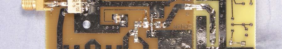
7 The combline filter is followed by a x3 multiplier, A2, an overdriven MMIC. There is a test point after the filter use C3 to temporarily connect the test point rather than the MMIC, and slip an SMA connector over the test point. You should measure about +5 dbm at 240 MHz at the test point. This is enough power to overdrive a MAR-1 and produce enough distortion to generate the third harmonic. The MAR-1 current is set by the bias resistor, R3, for maximum output at 720 MHz, measured after the next filter. You may fiddle this resistor value if you have a need to adjust something. Figure MHz Filter end of LO board The multiplier output passes through the hairpin filter at 720 MHz. This filter has edgecoupled input and output, unlike the usual tapped-input configuration. Edge coupling produces sharper skirts and better stopband rejection below the operating frequency, ideal for eliminating fundamental and 2 nd harmonic outputs from the multiplier. A plot of the 720 MHz filter performance is shown in Figure 9. The edge coupling requires very tightly controlled spacing of the lines, but within the capabilities of ExpressPCB. There is another test point after the hairpin filter. Use a jumper to connect the testpoint before A3 is mounted. Typical signal level after the hairpin filter is -16 dbm at 720 MHz. This testpoint is probably unnecessary since the MAR-6 amplifier has predictable performance. A3 brings the output level up to around +5 dbm, which is what we need to
8 drive the transverter. All the other harmonics of 240 MHz are at least 33 db down except 1440 MHz, which is less than 20 db down. Hairpin Filter for 720 MHz 0 Insertion Loss (db) Measured Simulated. Frequency (MHz) Figure 8 If, for some reason, you desire more output power, a bit of work with an X-Acto knife will make spaces (a blocking capacitor and bias resistor are needed) in the transmission line following A3 for an additional MMIC amplifier; the grounding pads are already there. An MSA-11 would make a good higher power stage. One final note about the oscillator, since the ones I used may not be available forever, but 80 MHz seems to be a popular frequency. To try some alternatives, I bought a couple of batches of 80 MHz oscillators on Ebay. One batch apparently needs a negative voltage, so was tossed after smoking a couple. The other batch has a softer waveform, less like a square wave, so there is less third harmonic in the output. The level was about 10 db low after the 240 MHz filter. I added a low-gain MMIC, a MAR-7, in place of A2 before the MAR-1 multiplier to bring the level up. Again, the grounding pads are in place for an extra stage just cut an opening in the transmission line after A2 with an X- Acto knife. The MAR-7 bias resistor was 180 ohms. The whole LO board requires about 1 watt of power, 12 volts at 80 milliamps, so it could be run continuously for better stability. For backpackers, all but the oscillator could be powered down. One LO board could be used for multiple transverters, further reducing power needs. For more flexibility, they are cheap enough to use a separate LO board for each band a complete LO board probably costs less than a crystal for a surplus brick oscillator.

9 What about phase noise? We are only using a cheap computer oscillator. Will it be good enough for serious operation? At the Eastern VHF/UHF Conference in April, 2008, I had a chance to have it measured. Greg Bonaguide, WA1VUG, was kind enough to set up some impressive Rohde and Schwarz test equipment, including a FSUP50 combination Spectrum Analyzer and Signal Source Analyzer, good to 50 GHz. With this instrument, we were able to measure the phase noise at the 720 MHz output, shown in Figure 10. Figure 9 Phase Noise Plot of 720 MHz Output The phase noise is quite good, showing that the oscillator is a good crystal oscillator. It would be difficult to find a phase-locked source with better phase noise many of us prefer the tradeoff of a clean oscillator rather than exact frequency readout.

10 Part 3: Transverter for 2304 and 3456 MHz When I finished my 5760 MHz single-board transverter 5 back in 1997, it occurred to me that it would work well on 3456 with retuned pipe-cap filters, if the mixer were changed. However, moving the mixer down in frequency would require more real estate, and real estate is expensive on Teflon PC board. Sometime later, it occurred to me that a larger pipe-cap might cover both 2304 and 3456 MHz, so one transverter layout might work on both bands, if a mixer could cover both bands. I had a couple in the junkbox won as prizes at a VHF conference. A visit to the Minicircuits 6 website showed these to be a rather expensive model, but several inexpensive mixers would also do the job. I chose the ADE-18W as a reasonably priced ($3.95) one which looked like it could be hand-soldered some of the other surface mount models don t have accessible leads. The next question was whether it would all fit on an ExpressPCB Miniboard, the cheapest source for manufactured PC boards $59 for three boards. The Miniboard only comes in one size, 2.5 x 3.8. Working with the free ExpressPCB software, I was able to fit four 1 pipe-caps on the board, shown in Figure 11. The 5760 board has five, but also has separate transmit and receive mixers, each with a filter. By using a common mixer, the number could be reduced to four. Figure 11. Pipe-cap Filter Side of Transverter Board
11 The schematic diagram of the transverter board is shown in Figure 12. Two of the pipecap filters are used to complete the LO chain, taking the 720 MHz output from the LO board and multiplying one more time. The multiplier is either x3, to 2160 MHz, or x5, to 3600 MHz, using an overdriven ERA-2 MMIC as the multiplier, A4. I also tried a MAR- 1 for A4, but didn t get enough output, even as a x3 multiplier. Following the multiplier is a pipe-cap filter, another MMIC, and a second pipe-cap filter, to provide a clean LO signal to the mixer. The second MMIC, A5, is an ERA-2 at 3600 MHz, but a lower gain ERA-1 is sufficient at 2160 MHz. Note that there are only two resistor values and four capacitor values on the board, all ordinary chip components. Figure 12. Schematic of Transverter Board for 2304 and 3456 MHz
12 A single mixer, the ADE-18W, is used for both transmit and receive. The IF port is brought out to a connecter, to provide 144 MHz output on receive and input on transmit. The transmit IF level should be no more than 0 dbm at 144 MHz. The output of the mixer goes to the third pipe-cap filter to remove the image and any LO leakage, then to a resistive splitter to separate transmit and receive. My first prototype used three probes in the pipe-cap for separate transmit and receive, a trick that K2CBA used in his Easyverter 7. It worked, but getting the probes matched proved to be touchy, and the loss was no better than the resistive splitter. Two extra resistors are easier than something requiring adjustment. The transmit path has an ERA-2 amplifier, A2, the fourth pipe-cap filter, and an ERA-5 power amplifier, A3. The receiver uses a low-noise GaAs MMIC, the MGA-86576, at A1 to overcome the loss of the mixer and filter. Noise figure should be more than adequate for a low power station. The front-end is wide open, so a real filter is suggested for operation on mountaintops or near cell towers. Assembly and Tuneup The first step in assembly is to solder the pipe caps to the board, after drilling and tapping the screw holes in the top of the caps. Each pipe-cap location has a hole at the center, halfway between the probe locations. I scribe lines on the bare board 5/8 away from the center hole, making a square to line up each pipe cap. Then I put a bit of paste flux on the rim of each cap, place the caps in position, and put a ring of wire solder around the base of each cap. I solder the caps one at a time, holding the one being soldered in position with a screwdriver while heating the top of the cap with a hot air gun. The copper conducts the heat down to the board; when the joint reaches temperature, the ring of solder melts and flows around the base of the cap, without overheating the board. As soon as the solder flows, remove the heat, let it cool until the solder solidifies, then move on to the next cap. A torch could also be used, but tends to oxidize the copper. All other components are surface-mount, on the side of the board opposite the pipe caps, shown in Figure 13. I recommend No-clean solder like Kester 245, preferable in diameter or smaller then we don t have to worry about cleaning liquids getting into the pipe caps and other unwanted places. Tin-lead solder works fine, and there is no reason for hams to worry about lead-free solders.

13 Figure 13. Component side of transverter board, configured for 2304 MHz Next, decide which band the transverter is to operate on. Two things determine the operating frequency: the depth of the tuning screws in the pipe-cap filters, and the length of the quarter-wave printed choke lines on the MMIC amplifiers. The electrical length is determined by the position of the bypass capacitors these are the same cheap 18 pf chip capacitors used for the 240 MHz filter. For 2304 MHz, the full length of the choke line is used, so the capacitors go at the end, while for 3456 MHz, the capacitors should be placed on the wide area at about 2/3 of the length. Figure 14 is a closeup of the transmit output amplifier, A5, illustrating the capacitor placement for each band.

14 Figure 14 Closeup of final Transmit amplifier, illustrating capacitor placement for each band. The pipe-cap filter frequency is determined by the length of the tuning screw inside the cap, acting as a quarter-wave resonator. The probe length determines the selectivity of the filter a short probe is lossy with critical tuning, while a long probe produces a broad response with poor selectivity. A good length for the probes for both bands is about inside the cap for 3456 MHz, and for 2304 MHz. I measure the length on a straight piece of wire, add for the board thickness, and notch the wire with a wirecutter. Then I insert the wire into the hole in the board until the notch is flush with the top surface, clamp it so it is perpendicular to the board, and solder it. Then I cut it off leaving a small nub to grab with tweezers if removal is necessary. Tuneup is easier if components are added sequentially, starting with the LO section. A test point before the mixer allows tuning up the LO multiplier, using C6 to connect the SMA connector test pad. Connect the LO board to supply drive at 720 MHz. Start with the screws, 1.25 long brass screws, all the way in both pipe-caps, touching the board under the cap. Then back both screws out together until some signal is detected, and peak the output. This peak is at 2160 MHz. For 3600 MHz, continue backing the screws out past a second peak, at 2880 MHz, to a third peak at 3600 MHz. Output power should be +6 dbm or more at the test point, enough to drive the mixer. Figure 14 is a closeup of
, making sure to align it according to the picture, Figure 16.")
15 the LO section of the board. Note that the capacitors are at the shorter location on the quarter-wave chokes this copy is for 3456 MHz. Then move C6 to connect the LO to the mixer. Solder the mixer down carefully, since the bottom is open (turn it over and admire the tiny transformers first), making sure to align it according to the picture, Figure 16. The mixer pipe-cap filter is tuned using the receive port as a test point, jumpering the MMIC location A1 with a wire as shown in Figure 17. Only the splitter resistor, R1, is needed at this point. With only the LO running, set the pipe-cap tuning screw the same height as the LO screws, then tune for a peak this is at the LO frequency. Then apply 0 dbm at 144 MHz to the IF port. Now adjust the screw for a larger peak at the Figure 15 LO section of Transverter board


16 RF frequency: 2304 MHz is higher than the 2160 MHz LO, so the screw should be backed out of the pipe cap to peak, but 3456 MHz is lower than the 3600 MHz LO so the screw should be tuned in to the cap for a peak. Tuning in the wrong direction will peak on the image frequency. Output from the receive port, being used as a test point here, should be on the order of -13 dbm. Check the output frequency if you can. Figure 17. RX port used for filter tuneup, with wire jumper in place of A1 Remove the jumper wire from the A1 location, then assemble the transmit section. The driver stage, A4, is shown at the bottom of Figure 18, right, and the final stage, A5, in Figure 14. Set the final tuning screw to the same height as the mixer screw, power it up, and apply 0 dbm at 144 MHz to the IF port. Peak the pipe-cap tuning for maximum output, at least +10 dbm. Finally, assemble the receive section as shown in Figure 18. Power the receive MMIC with about 5 volts (everything else runs on 8 volts) and connect a two-meter receiver to the IF. Stick a short wire in the SMA jack and tune in a signal harmonics of my 1152 MHz marker are loud from across the basement. If you can measure noise figure, adjust the voltage to the receive MMIC to optimize best noise figure should be somewhere between 5 and 7 volts.
17 Part MHz Transverter The transverter for 1296 MHz has the same design philosophy as the transverters for higher bands gain is cheap. At the lower frequency, it is even cheaper, since the older MAR series of MMICs provide adequate gain. The schematic diagram for this transverter, in Figure 19, is similar to the others: LO input at 720 MHz from the common oscillator, an LO multiplier and amplifier, a mixer, and amplifiers for transmit and receive. Filters are 3-section printed hairpin filters rather than pipe-caps; the printed filters have a bit more loss, but don t require any tuning. Anyway, pipe-cap type filters would have to be nearly 2 inches high, assembled out of bits of pipe the simplicity would be lost. Figure 19 Schematic Diagram of 1296 MHz Transverter


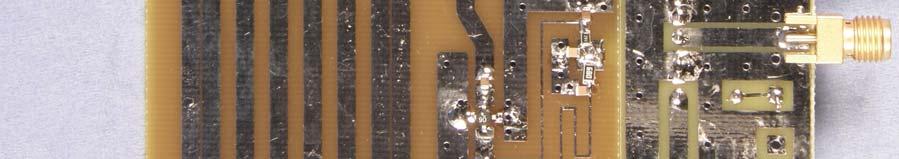
18 The transverter fits the Miniboard size limit from ExpressPCB, but there is only room for one LO filter and one RF filter. Figure 20 is a photo of a complete transverter board. Assembly is not difficult, and no tuneup is required it just works. There is adequate LO power for the mixer, and drive for the LO multiplier is not critical a reduction of 6 db in drive at 720 MHz reduces LO output from +8 dbm to +5 dbm, well within the recommended mixer LO range. Transmit power output is about 15 dbm, adequate for a simple rover rig, or more than enough to drive another transverter for a much higher microwave band. Figure 20 Transverter board for 1296 MHz I chose another cheap mixer from Minicircuits, but not the same one used for 2304 and 3456 models that cover all three bands are more expensive. Although the package looks the same, it uses a different pinout. Figure 21 shows the mixer and 1296 MHz printed hairpin filter.

19 Figure 21 Mixer and 1296 MHz Hairpin Filter The hairpin filters provide good performance in a compact space. Figure 22 shows the performance of both filters. The correlation with the simulated performance, shown as dashed lines, is very good the 720 MHz filter, in Figure 9, was used to better estimate the dielectric constant of the printed-circuit material for better accuracy. This might be worth a future paper. Figure 22 Performance of Printed Hairpin Filters for 1296 and 1440 MHz, Measured (solid line) and Simulated (dashed line)
20 Because of the limited filtering, the LO and image frequencies are only about 30 db down. This is probably OK for rover operation, but not for long term or high power operation the LO frequency, 1440 MHz is near enough to radio astronomy frequencies to attract some attention. For serious work, more filtering is needed, with real metal filters 2,3. The prototype used a MAR-6 MMIC for the receive amplifier, which does not provide enough gain to overcome the loss of the mixer, filter, and splitter, roughly 18 db total loss. I replaced it with an INA MMIC for higher gain and better noise figure, at the expense of a little higher operating current. The receive and transmit amplifiers are shown in Figure 23. Figure 23 Receive and Transmit Amplifiers for 1296 MHz All the other parts should also be readily available and reasonably priced. The resistors and capacitors are commodity parts, not expensive microwave parts. The MMICs are available from Down East Microwave 1, and PC boards will be available. There is probably enough activity on 1296 in some areas to justify a high-performance transverter rather than a simple one, but the simple one could be a good way to try out the band or get a rover on. A simple transverter might also be useful as a first IF for 24 GHz or higher bands.
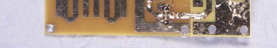
21 The final limitation is that the LO injection is high side, so that MHz comes out at MHz, and tunes backwards, reversing USB and LSB. This can be annoying, but just remember that the cost of the whole transverter is about the same as the cost of a custom crystal. The LO multiplier and amplifier are shown in Figure 24, as well as the mixer. The 720 MHz input uses a low-cost Type-F connector. Figure 24 LO Multiplier to 1440 MHz and LO Amplifier driving Mixer

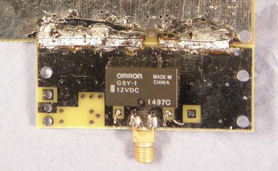
22 Part 5: Coax Relay For T-R switching, most microwave transverters use an SMA coax relay like the one in Figure 25. Good ones can be more expensive than one of these transverters, while surplus ones can be problematic many are worn out and have intermittent contacts. Most of them require 28 volts to operate, and require more power than these transverters use. One possible alternative is some of the PC-mount relays intended for wireless applications. The Omron G6Y-1 relay in Figure 26 is rated for up to 10 watts at frequencies to 2.5 GHz, and operates from 12 volts. They are readily available for a few dollars, and Down East microwave uses them in some products. I tested one on the board shown it looks good to about 3.5 GHz, with about 1 db of loss. Part of the loss is probably due to the PC board. Figure 26 Inexpensive RF Relay Omron G6Y-1 A similar relay, the Omron G6Z-1F-A, shown in Figure 27, uses surface mount construction and gets slightly better performance, with lower loss particularly at 3456 MHz. This version is roughly the same cost, but operates up to around 6 GHz with perhaps 3 db of loss hard to say how much is due to the PC board. Surface mount assembly is slightly more difficult, but it enables removal of the plated-thru holes which add capacitance and affect performance at the higher frequencies. One version of the relay PC board has no holes for the relay, so it only works with the surface mount relay. The Omron G6Z-1F-A has one other quirk the coil is polarized, so that it only operates when the positive voltage is at the end of the coil away from the end with the dot at the upper left in Figure 27.
23 Figure 27 Surface Mount RF Relay Omron G6Z-1F-A Sometimes it is undesirable to drive the relay coil directly, so there are locations on the board for a simple relay driver circuit. Figure 28 shows the schematic for a circuit of either polarity. See the parts placement diagrams for part locations. Figure 28 Simple relay driver circuits The small PC boards for the relay are designed to line up with the TX and RX ports on all the transverters, to connect directly and eliminate several SMA connectors. Figure 29 shows a 1296 transverter with relay attached, connecting each transmission lines with a couple of wires in parallel. On the back side, the two ground planes are bridged together with Solder-wick braid, shown in Figure 30.


24 Figure Transverter with attached RF Relay Figure 30 Ground plane side
25 Part 6: System So far, we have described a basic transverter, not a complete system. For an operational station, we need something to interface with the IF transceiver. The TC (Transverter Control IF switch) kit from Down East Microwave 8 will do the switchover, reducing power on transmit, and can also generate 24 volts for surplus coax relays. At these low power levels, we could skip the relay and use two separate antennas, perhaps modest horns. Both transverter and LO boards are biased to run from an 8-volt supply. One easy way to get this is to change the 3-terminal regulator on the TC board to an 8-volt regulator like a The receive amplifier for 2304 or 3456 MHz, A1 on the transverter board, requires a lower voltage a small adjustable 3-terminal regulator, like an LM317L, will do the job. Just remember bypass capacitors on both sides of the regulators or you may make an oscillator. The complete unit should be packaged in some sort of metal box. The transverter board and LO board are best mounted to a metal surface on short standoffs, with the MMIC side of the boards facing the metal surface to reduce stray radiation. If multiple transverters are to be sourced from one LO board, a power splitter is needed, followed by some gain to make up the splitter loss. A sketch for a power splitter is shown in Figure30. Resistor R should be 51 ohms for a two-way splitter, 100 ohms for a three-way, or 150 ohms for a four-way splitter. Gain to get back to the input level is about 6 db for a two-way splitter, plus another 3 db for each additional output. A fancy PC board isn t really needed a quick X-Acto knife special, or a perf board or just dead-bug construction will do the job. A couple of extra db of gain from the MMICs will make up for any imperfections. Figure 31. LO power splitter


26 Another choice for the power splitter would be the inexpensive ones made for satellite TV distribution. They are nominally 75 ohms and have Type-F connectors, like the LO board and 1296 MHz transverter shown above. A selection of splitters is shown in Figure 31. They work well in a 50 ohm system from about 300 MHz to >1300 MHz, with each output about 6 db down. The exception is the unit in the lower right, which seems to be a diplexer, separating different frequency bands. So make sure to use one marked SPLITTER. Figure 32 CATV Splitters make good LO power splitters. There is always the temptation to go for higher performance. Surplus power amplifiers are available for both bands, and C-band TVRO equipment can be converted into an inexpensive low-noise preamp. I d strongly suggest adding real filters, metal ones 9, before driving a high power amplifier or with a preamp.
27 A bit of history The description above sounds carefully planned and engineered, but it really wasn t. I started with two ideas: the 720 MHz scheme for multiple bands, and the two-band pipe cap transverter. Even though I hadn t figured out how to get to 720 MHz, I built a transverter. It didn t work! The LO stages had very low gain and tuning was impossibly sharp. At first, I thought something was wrong with the MMICs. I set it aside for a while. Over time, I kept thinking about it, and finally figured out workable filters for the 720 MHz board. Then I went back and analyzed the pipe-cap filters 11, and realized that the probes I had used were much too short, making the filters very sharp and lossy. Once the probes were corrected, things started to work. Then I found that the mixer footprint was backwards on the board, so I had to patch a mixer on. But it still worked, so I corrected the board and made some more, to show the transverter is reproducible. The lesson here is to stick with an idea long enough to see if it s a good one. It may not go where you planned, but you won t know without trying. Antennas Simple horn antennas can provide good results for a rover station, providing good gain in a robust, easy to point, package. With a little effort, we could come up with a dual-band horn for 2304 and 3456 MHz. A small dish antenna can provide a bit more gain at the expense of a narrower beam, making aiming more critical. Multiband feeds are not optimum, but are simple and good for rover use. I d recommend WA5VJB s log periodic 12 as a multiband dish feed 13 or just as a small antenna with modest gain. A log periodic also works fine as a simple rover antenna with about 6 db gain, plenty for shorter contacts. For more antenna details, see the W1GHZ Microwave Antenna Book Online 14. Summary These microwave transverters should be relatively simple to build, and fun for those who enjoy homebrewing. I believe there are enough hams who still homebrew to justify having some boards made and making them available. These transverters can be used in an affordable basic system or as building blocks for higher performance. Board layouts, parts lists, and closeup photos are available on my website,
28 References 1. Wade, Paul, W1GHZ, A 222 MHz transverter for the Yaesu FT-817, QST, January 2003, pp Paul Wade, N1BWT, A Single-board Transverter for 5760 MHz and Phase 3D, QEX, November 1997, pp also Judson Snyder, K2CBA, The 10 GHz Easyverter, Proceedings of the 25 th Eastern VHF/UHF Conference, ARRL, 1999, pp Paul Wade, W1GHZ, Waveguide Interdigital Filters, QEX, January 1999, pp Paul Wade, W1GHZ, A Single-Board Transverter for 10 GHz, Proceedings of the 25 th Eastern VHF/UHF Conference, ARRL, 1999, pp also in Andy Barter, G8ATD, ed., International Microwave Handbook, RSGB & ARRL, 2002, pp Paul Wade, W1GHZ, Pipe-cap Filters Revisited, Kent Britain, WA5VJB, Designing PCB Log Periodic Antennas, Proceedings of Microwave Update 2000, ARRL, 2000, pp Paul Wade, W1GHZ, The WA5VJB LPA Antenna as a Multi-band Dish Feed, Proceedings of the 38 th Conference of the Central States VHF Society, ARRL, 2004, Paul Wade, W1GHZ, W1GHZ Microwave Antenna Book Online,
Multiband Microwave Transverters for the Rover Simple and Cheap
 Multiband Microwave Transverters for the Rover Simple and Cheap Paul Wade W1GHZ 2008 w1ghz@arrl.net update 16 April 2008 Operating on multiple microwave bands in VHF contests will greatly enhance a score,
Now Four Bands, adding 902 MHz
 Multiband Microwave Transverters for the Rover Simple and Cheap Now Four Bands, adding 902 MHz Paul Wade W1GHZ 2008 w1ghz@arrl.net Operating on multiple microwave bands in VHF contests will greatly enhance
Altoids Tin Filters. Paul Wade W1GHZ 2014
 Altoids Tin Filters Paul Wade W1GHZ 2014 w1ghz@arrl.net Several years ago, I described a series of "Multiband Microwave Transverters for the Rover - Simple and Cheap " (www.w1ghz.org), with several later
Locked VCXOs for Stable Microwave Local Oscillators with Low Phase Noise
 Locked VCXOs for Stable Microwave Local Oscillators with Low Phase Noise Paul Wade W1GHZ 2013 w1ghz@arrl.net A good local oscillator has been a perennial problem for microwave operators. An ideal LO would
Locked VCXOs for Stable Microwave Local Oscillators with Low Phase Noise
 Paul Wade, W1GHZ 582 Dubray Rd, Cabot, VT 05647; w1ghz@arrl.net Locked VCXOs for Stable Microwave Local Oscillators with Low Phase Noise This Article is Reprinted from The Proceedings of Microwave Update
Simple Cheap MMIC Preamps
 Simple Cheap MMIC Preamps Who needs a GaAsFET? Paul Wade W1GHZ 2014 w1ghz@arrl.net I have tried some of the newer MMICs from Minicircuits 1 as moderate power amplifiers 2,3, providing several hundred milliwatts
High-Power Directional Couplers with Excellent Performance That You Can Build
 High-Power Directional Couplers with Excellent Performance That You Can Build Paul Wade W1GHZ 2010 w1ghz@arrl.net A directional coupler is used to sample the RF energy travelling in a transmission line
Portable RF Sniffer and Power Meter
 Portable RF Sniffer and Power Meter Paul Wade W1GHZ 2003, 2004 RF power meters are extremely useful instruments. Whether we are tuning up homebrew equipment, checking antenna VSWR, adjusting a linear amplifier,
Updating KK7B, SHF,DEM or DEMI 900 and 1296 MHz. transverters
 Updating KK7B, SHF,DEM or DEMI 900 and 1296 MHz. transverters By Steve Kostro, N2CEI PREFACE: Yes, It may be hard to believe, but the original 900 and 1296 No-Tune transverter concepts have been around
The 144MHz Anglian 3 transverter
 The 144MHz Anglian 3 transverter A high performance 144/28MHz transverter G4DDK document issue 1 12/9/16 Introduction Anglian 3 is an update to the 144MHz Anglian 2 transverter. The Anglian 2 is no longer
75 Meter SSB Project Design by KD1JV Built by Paul Jorgenson KE7HR NSS 39382FE
 75 Meter SSB Project Design by KD1JV Built by Paul Jorgenson KE7HR NSS 39382FE After completing a 75 meter DSB project (and using it underground, caving), I wanted to try building a SSB rig. I was searching
Combline Filters for VHF and UHF Paul Wade W1GHZ 2014, 2015 (update)
") Combline Filters for VHF and UHF Paul Wade W1GHZ 2014, 2015 (update) w1ghz@arrl.net RF pollution is rampant at good portable locations on mountaintops and other high places anywhere accessible is populated
Combline Filters for VHF and UHF Paul Wade W1GHZ 2014, 2015 (update) w1ghz@arrl.net RF pollution is rampant at good portable locations on mountaintops and other high places anywhere accessible is populated
DEM ABPM KIT All Band Power Meter Assembly Notes and Pictures
 DEM ABPM KIT All Band Power Meter Assembly Notes and Pictures Paul Wade W1GHZ w1ghz@arrl.net Down East Microwave has kindly agreed to make kits available for my All Band Power Meter (Note: I receive no
Alcatel White Box 24GHz Transceiver experiments and modifications
 Alcatel White Box 24GHz Transceiver experiments and modifications A set of working notes, measurements and comments PSU Need to supply : -5V up to ~ 30mA for Rx and PA modules +5.2V 1A for Rx and Tx mixer
DEM Part Number L144-28INTCK 144 MHz Transverter Kit and complete kit
 DEM Part Number L144-28INTCK 144 MHz Transverter Kit and complete kit Power Out: Noise Figure and Gain: DC Power Requirement: 50 mw linear minimum 3.5 db NF nominal, 5 dbg maximum 12-15.5 VDC, 13.8 nominal
DEM TC DEM TRANSVERTER CONTROL
 DEM TC DEM TRANSVERTER CONTROL The DEM Transverter Control (DEM TC) is the circuit board that controls all transverter functions in the DEMI 2.3 GHz. -10 GHz. transverters. It was designed with many options
Application Note 5011
 MGA-62563 High Performance GaAs MMIC Amplifier Application Note 511 Application Information The MGA-62563 is a high performance GaAs MMIC amplifier fabricated with Avago Technologies E-pHEMT process and
Phase Noise and MDS. Paul Wade W1GHZ 2009
 Phase Noise and MDS Paul Wade W1GHZ 2009 w1ghz@arrl.net There has been a lot of noise about phase noise recently, but very little data. We know that older FM rigs with synthesizers sounded terrible on
LNB and its ham radio usage
 http://ea4eoz.blogspot.gr/2012/09/lnb-and-its-ham-radio-usage.html LNB and its ham radio usage The letters LNB means Low Noise Block, but we must call it LNC, this is Low Noise Converter, because a LNB
A simple, yet still fool-resistant, sequencer for transverters New version with LED indicator for power output
 A simple, yet still fool-resistant, sequencer for transverters New version with LED indicator for power output Paul Wade W1GHZ 2002, 2003 w1ghz@arrl.net The availability of reasonably high-power microwave
My Pre-amp doesn t work!
 My Pre-amp doesn t work! A design, troubleshooting, and repair guide for all modern day GaAs FET or PHEMPT type low noise amplifiers. DEMI by N2CEI, Steve Kostro PREFACE For anyone that considers themselves
High Intercept Low Noise Amplifier for 1.9 GHz PCS and 2.1 GHz W-CDMA Applications using the ATF Enhancement Mode PHEMT
 High Intercept Low Noise Amplifier for 1.9 GHz PCS and 2.1 GHz W-CDMA Applications using the ATF-55143 Enhancement Mode PHEMT Application Note 1241 Introduction Avago Technologies ATF-55143 is a low noise
Handbook / Kit. DB 6 NT 2,3 GHz Transverter MK DB 6 NT
 Handbook / Kit DB 6 NT 2,3 GHz Transverter MK2 4.2003 DB 6 NT 2.3 GHz Transverter MK2 DB6NT 4.2003 Introduction This transverter is a further development of the schematic published in 1993. Technical data
DEM Part Number K, CK and LPK and CK 5.7 GHz. Transverter, Low Power Transverter, Kit and Complete Kit
 DEM Part Number 5760-144K, CK and 5760-144LPK and CK 5.7 GHz. Transverter, Low Power Transverter, Kit and Complete Kit Specifications Frequency: 5760.000 = 144.000 standard Noise Figure and Gain < 1.5
MARTIN - G8JNJ ECLECTIC AETHER - ADVENTURES WITH AMATEUR RADIO
 MARTIN - G8JNJ ECLECTIC AETHER - ADVENTURES WITH AMATEUR RADIO REDUCING RTL DONGLE INTERNAL SPURII AND NOISE SIGNALS I ve recently bought quite a few RTL DVB-T RTL 2832U / Rafael Micro R820T dongles to
Application Note 5012
 MGA-61563 High Performance GaAs MMIC Amplifier Application Note 5012 Application Information The MGA-61563 is a high performance GaAs MMIC amplifier fabricated with Avago Technologies E-pHEMT process and
Overview of the MSA 12/30/10
 Overview of the MSA 12/30/10 Introduction The purpose of this document is to provide an overview of the capabilities and construction of the MSA to help potential builders get oriented. Much more detailed
The K290R Project. Steve Kavanagh, VE3SMA, December 2017
 The K290R Project Steve Kavanagh, VE3SMA, December 2017 Background I have been using a pair of Yaesu FT-290R 2m transceivers as IF rigs for microwave transverters for many years. My 2.3, 3.4, 5.7, 10 and
Range Considerations for RF Networks
 TI Technology Days 2010 Range Considerations for RF Networks Richard Wallace Abstract The antenna can be one of the most daunting components of wireless designs. Most information available relates to large
A Flip-Switch 10/24 GHz Dual Band Radio
 A Flip-Switch 10/24 GHz Dual Band Radio Gary Lauterbach, AD6FP Introduction I had a great time in my first 10 Ghz and up contest in 1999 even though I was only able to operate for a few hours on the second
Directly Synthesized 47 GHz Local Oscillator. Garry C. Hess, K3SIW February 18, 2007
 Directly Synthesized 47 GHz Local Oscillator Garry C. Hess, K3SIW February 18, 2007 Introduction. This note describes a means of directly synthesizing the local oscillator for a 47 GHz transverter. The
DEM Part Number K, CK and LPK and CK 5.7 GHz. Transverter, Low Power Transverter, Kit and Complete Kit
 DEM Part Number 5760-144K, CK and 5760-144LPK and CK 5.7 GHz. Transverter, Low Power Transverter, Kit and Complete Kit Specifications Frequency: 5760.000 = 144.000 standard Noise Figure and Gain < 1.5
Yana Dongles Tom Berger K1TRB (c)2016 v171227
2016 v171227") Yana Dongles Tom Berger K1TRB (c)2016 v171227 These notes elaborate some items described in the Build notes, and add some more dongles enhancing Yana. Every effort has been exerted to save on the cost
Yana Dongles Tom Berger K1TRB (c)2016 v171227 These notes elaborate some items described in the Build notes, and add some more dongles enhancing Yana. Every effort has been exerted to save on the cost
144MHz direct conversion receiver with I/Q outputs for use with Software Defined Radio.
 144MHz direct conversion receiver with I/Q outputs for use with Software Defined Radio. Overview This design is a direct conversion receiver for 144MHz with quadrature outputs for use either with a software
A 75-Watt Transmitter for 3 Bands Simplified Shielding and Filtering for TVI BY DONALD H. MIX, W1TS ARRL Handbook 1953 and QST, October 1951
 A 75-Watt Transmitter for 3 Bands Simplified Shielding and Filtering for TVI BY DONALD H. MIX, W1TS ARRL Handbook 1953 and QST, October 1951 The transmitter shown in the photographs is a 3-stage 75-watt
Construction Hints and Techniques
 Construction Hints and Techniques You just get finished building a Microwave project and it looks beautiful. After admiring it for awhile you decide to spark it up. All of the voltages and currents look
Construction Manual 4m-Linear-Transverter XV4-15
 Construction Manual 4m-Linear-Transverter XV4-15 Holger Eckardt DF2FQ Kirchstockacherstr. 33 D-85662 Hohenbrunn 3207 Technical data exciter frequency: 21.0... 21.5 MHz RF frequency: 70.0.. 70.5 MHz supply
12kHz LIF Converter V2.43 9Mhz version
 12kHz LIF Converter V2.43 9Mhz version Please Note: This document supersedes all previously released documents and drawings on the LIF subject. This is the latest and most up-to-date document at this time.
Connecting the FCC-2 to the Hendricks DC Kits Bob Okas, W3CD
 Connecting the FCC-2 to the Hendricks DC Kits Bob Okas, W3CD This is an application note that describes how you can connect the NorCal FCC-1/2 combination to the DC kits. It involves a few extra components
RFID Systems: Radio Architecture
 RFID Systems: Radio Architecture 1 A discussion of radio architecture and RFID. What are the critical pieces? Familiarity with how radio and especially RFID radios are designed will allow you to make correct
Low Noise Amplifiers for 2304, 3456, 5760, and MHz using the ATF PHEMT by Al Ward WB5LUA
 Low Noise Amplifiers for 2304, 3456, 5760, and 10368 MHz using the by Al Ward INTRODUCTION The Hewlett-Packard device is described in a series of low noise amplifiers for 2304, 3456, 5760, and 10368 MHz.
Agenda 1. AML Amplifier Modification 2. MicroTik mmw Digital Link 3. Hints and Kinks
 Agenda 1. AML Amplifier Modification 2. MicroTik mmw Digital Link 3. Hints and Kinks Greg McIntire, AA5C AA5C@arrl.net November 3, 2018 WWW..ORG 1 AML Amplifier - 1 Surplus Brick Amplifier designed for
S-Pixie QRP Kit. Student Manual. Revision V 1-0
 S-Pixie QRP Kit Student Manual Revision V 1-0 Introduction The Pixie 2 is a small, versatile radio transceiver that is very popular with QRP (low power) amateur radio operators the world over. It reflects
A NEW TECHNIQUE FOR CONSTRUCTION OF 23CM SEPTUM FEED June 18, 2010 (Revised November 15, 2017)
") INTRODUCTION 1296 MHz EME popularity is growing this band seems to be the big attraction these days. Just acquire an old TVRO dish and you are on your way. This article will hopefully at least make the
INTRODUCTION 1296 MHz EME popularity is growing this band seems to be the big attraction these days. Just acquire an old TVRO dish and you are on your way. This article will hopefully at least make the
Application Note 5525
 Using the Wafer Scale Packaged Detector in 2 to 6 GHz Applications Application Note 5525 Introduction The is a broadband directional coupler with integrated temperature compensated detector designed for
Modifying the Qualcomm 1W Ku-Band PA for use on 3.4, 5.7 or 10.3 GHz
 Web Version 10-9-2001 Modifying the Qualcomm 1W Ku-Band PA for use on 3.4, 5.7 or 10.3 GHz K-Banke- 07/13/01 Hundreds of Ku-Band Qualcomm 1 watt power amplifiers have been modified and found their way
Construction Manual 6m-Linear-Transverter XV6/10
 Construction Manual 6m-Linear-Transverter XV6/10 Holger Eckardt DF2FQ Kirchstockacherstr. 33 D-85662 Hohenbrunn 2606 Technical data exciter frequency: 28... 30 MHz RF frequency: 50... 52 MHz supply voltage:
Assembly Instructions for the FRB FET FM 70 Watt Amp
 Assembly Instructions for the FRB FET FM 70 Watt Amp 1.) Orient the circuit board with the diagram 2.) Use a narrow chisel tip 25-30 watt soldering iron for assembly 3.) All the small parts are taped onto
Pacific Antenna Low Pass Filter Kit
 Pacific Antenna Low Pass Filter Kit Description Many basic transmitter and/or transceiver designs have minimal filtering on their output and frequently have significant harmonic content in their signals.
Components for modular microwave transverters. Wolf-Henning Rech DF9IC in JN48iw
 Components for modular microwave transverters Wolf-Henning Rech DF9IC in JN48iw http://www.df9ic.de Content Multiband transverter systems Filters and multiplexers PLL-disciplined oscillators Transverters
Handbook / Kit. DB 6 NT 5,7 GHz Transverter MK DB 6 NT
 Handbook / Kit DB 6 NT 5,7 GHz Transverter MK2 4.2003 DB 6 NT 5,7 GHz Transverter MK2 DB6NT 4.2003 3. Generation Indroduction In 1977 the DUBUS magazine published the first 5,7GHz SSB transverter which
A IVE-BAND, TWO-ELEMENT H QUAD
 A IVE-BAND, TWO-ELEMENT H QUAD Two quad designs are described in this article, both nearly identical. One was constructed by KC6T from scratch, and the other was built by Al Doig, W6NBH, using modified
A SDR-based receiver for Es hail-2 and the BACAR 6, 10 GHz beacons 30 July 2018
 A SDR-based receiver for Es hail-2 and the BACAR 6, 10 GHz beacons 30 July 2018 Hannes Coetzee, ZS6BZP Introduction If all goes according to plan the Qatar Satellite Company (Es hailsat) will place its
Modifying The Heath HA-14 For 6 Meters Greg Chartrand - W7MY 4/22/07
 Introduction The Heathkit HA-14 was one of the few electron tube linear amplifiers intended for mobile use but few were purchased with the 12 volt mobile power supply. Most hams bought the HA-14 for base
10 GHz LNA for Amateur Radio by K5TRA
 Introduction Ham radio operation on 10 GHz is somewhat exotic. This is far removed from global short-wave communication below 30 MHz, or regional VHF and UHF communication. Despite the arcane nature of
Build a 12/17 Meter Trap Dipole Phil Salas AD5X
 Build a 12/17 Meter Trap Dipole Phil Salas AD5X Introduction Why a 12/17 meter rotatable dipole? Well, many folks have verticals for the lower bands, and multi-band dipoles or beams for 20-, 15-, and 10
ATF High Intercept Low Noise Amplifier for the MHz PCS Band using the Enhancement Mode PHEMT
 ATF-54143 High Intercept Low Noise Amplifier for the 185 191 MHz PCS Band using the Enhancement Mode PHEMT Application Note 1222 Introduction Avago Technologies ATF-54143 is a low noise enhancement mode
RadiØKit Μ CW HAM RADIO TRANSCEIVER KIT. Assembly and operating manual
 RadiØKit-120 20Μ CW HAM RADIO TRANSCEIVER KIT Assembly and operating manual Boreiou Ipirou 78 Kolonos Athens- Greece - 10444 Tel: 210.5150527 210.5132673 www.freebytes.com Thank you for buying RadiØKit-1,
G6ALU 20W FET PA Construction Information
 G6ALU 20W FET PA Construction Information The requirement This amplifier was designed specifically to complement the Pic-A-Star transceiver developed by Peter Rhodes G3XJP. From the band pass filter an
Technical Specifications - Characteristics
 Watt FM TRANSMITTER General Description This is a small but quite powerful FM transmitter having three RF stages incorporating an audio preamplifier for better modulation. t has an output power of 4 Watts
Optimizing Your Stations Performance
 Optimizing Your Stations Performance A few hints / techniques, recommendations for getting the most RF out to the Antenna from your HF, VHF / UHF station. Tonights Presenters: Doug Theriault NO1D John
BY ALLEN W. KING,* W1CJL QST May 1955 *Project Engineer, Harvey-Wells Electronics, Inc., Southbridge, Mass.
 BY ALLEN W. KING,* W1CJL QST May 1955 *Project Engineer, Harvey-Wells Electronics, Inc., Southbridge, Mass. This comes close to being the ultimate in multiband antenna couplers, from the standpoint of
California Eastern Laboratories
 California Eastern Laboratories AN143 Design of Power Amplifier Using the UPG2118K APPLICATION NOTE I. Introduction Renesas' UPG2118K is a 3-stage 1.5W GaAs MMIC power amplifier that is usable from approximately
Today I would like to present a short introduction to microstrip cross-coupled filter design. I will be using Sonnet em to analyze my planar circuit.
 Today I would like to present a short introduction to microstrip cross-coupled filter design. I will be using Sonnet em to analyze my planar circuit. And I will be using our optimizer, EQR_OPT_MWO, in
N3ZI Kits General Coverage Receiver, Assembly & Operations Manual (For Jun 2011 PCB ) Version 3.33, Jan 2012
 Version 3.33, Jan 2012") N3ZI Kits General Coverage Receiver, Assembly & Operations Manual (For Jun 2011 PCB ) Version 3.33, Jan 2012 Thank you for purchasing my general coverage receiver kit. You can use the photo above as a
N3ZI Kits General Coverage Receiver, Assembly & Operations Manual (For Jun 2011 PCB ) Version 3.33, Jan 2012 Thank you for purchasing my general coverage receiver kit. You can use the photo above as a
Low Noise Amplifier for 3.5 GHz using the Avago ATF Low Noise PHEMT. Application Note 1271
 Low Noise Amplifier for 3. GHz using the Avago ATF-3143 Low Noise PHEMT Application Note 171 Introduction This application note describes a low noise amplifier for use in the 3.4 GHz to 3.8 GHz wireless
VCO Design Project ECE218B Winter 2011
 VCO Design Project ECE218B Winter 2011 Report due 2/18/2011 VCO DESIGN GOALS. Design, build, and test a voltage-controlled oscillator (VCO). 1. Design VCO for highest center frequency (< 400 MHz). 2. At
DEM Part Number CK and LPCK 10 GHz. Transverter, Low power Transverter, Kit and Complete Kit
 DEM Part Number 10368-144CK and 10368-144LPCK 10 GHz. Transverter, Low power Transverter, Kit and Complete Kit Specifications Frequency: 10368.000 = 144.000 standard Noise Figure and Gain < 1.5 db NF,
Feed Line Currents for Neophytes.
 Feed Line Currents for Neophytes. This paper discusses the sources of feed line currents and the methods used to control them. During the course of this paper two sources of feed line currents are discussed:
The J-Pole Antenna. Gary Wescom
 The J-Pole Antenna Gary Wescom - 2018 Much has been written about the J-Pole antenna. A simple Google search will net days worth of reading material on the subject. That would tend to indicate this paper
EEE 161 Applied Electromagnetics Laboratory 7 Microstrip Lines and PCB fabrication
 Dr. Milica Markovic Applied Electromagnetics Laboratory page 1 EEE 161 Applied Electromagnetics Laboratory 7 Microstrip Lines and PCB fabrication Part I. Design an impedance matching circuit using actual
Assembly Instructions
 Assembly Instructions For the SSQ-2F 3.1 MHz Rife Controller Board Kit v1.41 Manual v1.00 2012 by Ralph Hartwell Spectrotek Services GENERAL ASSEMBLY INSTRUCTIONS Arrange for a clean work surface with
MFJ Manual Loop Tuner Considerations
 Pagina 1 0 items Proceed to Secure Checkout All Categories Accessories Analyzers Products Tuners Morse Code / CW Power Supplies Product Search Search! List All Products Site Menu Customer Account Order
How to use your antenna tuner.
 How to use your antenna tuner. There's more to it than what is in your manual or on most how to do it websites! http://www.arrl.org/tis/info/ant-tuner-op.html Here is a neat site with a "T" network simulator.
1 TRANSISTOR CIRCUITS
 FM TRANSMITTERS The first group of circuits we will discuss are FM TRANSMITTERS. They can be called SPY TRANSMITTERS, FM BUGS, or a number of other interesting names. They all do the same thing. They transmit
Antenna Design for FM-02
 Antenna Design for FM-02 I recently received my FM-02 FM transmitter which I purchased from WLC. I researched the forum on what antennas where being used by the DIY community and found a nice write-up
The Design of E-band MMIC Amplifiers
 The Design of E-band MMIC Amplifiers Liam Devlin, Stuart Glynn, Graham Pearson, Andy Dearn * Plextek Ltd, London Road, Great Chesterford, Essex, CB10 1NY, UK; (lmd@plextek.co.uk) Abstract The worldwide
ECEN 5014, Spring 2009 Special Topics: Active Microwave Circuits Zoya Popovic, University of Colorado, Boulder
 ECEN 5014, Spring 2009 Special Topics: Active Microwave Circuits Zoya opovic, University of Colorado, Boulder LECTURE 3 MICROWAVE AMLIFIERS: INTRODUCTION L3.1. TRANSISTORS AS BILATERAL MULTIORTS Transistor
Design of an Evanescent Mode Circular Waveguide 10 GHz Filter
 Design of an Evanescent Mode Circular Waveguide 10 GHz Filter NI AWR Design Environment, specifically Microwave Office circuit design software, was used to design the filters for a range of bandwidths
WA3RNC 30 METER CRYSTALPLEXER TRANSMITTER KIT ASSEMBLY INSTRUCTIONS
 WA3RNC 30 METER CRYSTALPLEXER TRANSMITTER KIT ASSEMBLY INSTRUCTIONS Description The WA3RNC 30 Meter Crystalplexer is a low power crystal controlled QRP transmitter offering a significantly improved tuning
SWL Receiving Antenna Experiments
 SWL Receiving Antenna Experiments Introduction I have a lot to learn about SWL antennas. What follows are some brief experiments I performed in late October 2005. I have been experimenting with a half
Surface Mount SOT-363 (SC-70) Package. Pin Connections and Package Marking 4 V CC. Note: Package marking provides orientation and identification.
 Package. Pin Connections and Package Marking 4 V CC. Note: Package marking provides orientation and identification.") 1.5 GHz Low Noise Silicon MMIC Amplifier Technical Data INA-52063 Features Ultra-Miniature Package Single 5 V Supply (30 ma) 22 db Gain 8 dbm P 1dB Unconditionally Stable Applications Amplifier for Cellular,
1.5 GHz Low Noise Silicon MMIC Amplifier Technical Data INA-52063 Features Ultra-Miniature Package Single 5 V Supply (30 ma) 22 db Gain 8 dbm P 1dB Unconditionally Stable Applications Amplifier for Cellular,
10 GHz Microwave Link
 10 GHz Microwave Link Project Project Objectives System System Functionality Testing Testing Procedures Cautions and Warnings Problems Encountered Recommendations Conclusion PROJECT OBJECTIVES Implement
TS-930: Installing the Inrad Roofing Filter Mod
 TS-930: Installing the Inrad Roofing Filter Mod The TS-930 roofing filter mod consists of a 6 pole, 4 to 5 khz wide filter followed by a high dynamic range, feedback amplifier. The amplifier provides enough
SWR myths and mysteries.
 SWR myths and mysteries. By Andrew Barron ZL3DW September 2012 This article will explain some of the often misunderstood facts about antenna SWR at HF and uncover some popular misconceptions. The questions
Build Notes Si570 Controller II - by Pete Juliano N6QW,
 Build Notes Si570 Controller II - by Pete Juliano N6QW, radioguy90@hotmail.com (As of June 10, 2012) I bought just the board and programmed Micro Controller Unit from K5BCQ. Therefore I had to purchase
EEC 134 Final Report
 EEC 134 Final Report Team Falcon 9 Alejandro Venegas Marco Venegas Alexis Torres Gerardo Abrego Abstract: EEC 134 By Falcon 9 In the EEC 134 course the focus is on RF/microwave systems design. The main
A 100-Watt Transmitter Using a Pair of VT1625s
 12/16/2007 6:00 PM VT1625 100 Watt Transmitter A 100-Watt Transmitter Using a Pair of VT1625s FIG. 10.6 A 100-watt transmitter for five bands, using salvaged TV power transformer and surplus 1625 amplifier
47 GHz Waveguide Harmonic Mixer
 47 GHz Waveguide Harmonic Mixer These slides present an evolution of harmonic mixer construction ideas. The first slides depict the first harmonic mixer construction details and the later slides depict
ALX-SSB 5 Band Filter Assembly Manual 19 November 2018
 ALX-SSB 5 Band Filter Assembly Manual 19 November 2018 Contents Theory of Operation:... 1 Figure 1... 2 Parts Included:... 4 Board Overview:... 5 Figure 2... 5 Figure 3... 5 Board Assembly:... 6 Cable
Low Cost Mixer for the 10.7 to 12.8 GHz Direct Broadcast Satellite Market
 Low Cost Mixer for the.7 to 12.8 GHz Direct Broadcast Satellite Market Application Note 1136 Introduction The wide bandwidth requirement in DBS satellite applications places a big performance demand on
Technician Licensing Class. Lesson 4. presented by the Arlington Radio Public Service Club Arlington County, Virginia
 Technician Licensing Class Lesson 4 presented by the Arlington Radio Public Service Club Arlington County, Virginia 1 Quiz Sub elements T6 & T7 2 Good Engineering Practice Sub element T8 3 A Basic Station
VHF/UHF Dual Band J-Pole. By: Ed Fong WB6IQN
 VHF/UHF Dual Band J-Pole By: Ed Fong WB6IQN email: edison_fong@hotmail.com ARRL VHF/UHF Antenna Classics ARRL Vol. 8 Antenna Compendium ARRL Vol. 3 Antenna Compendium QST March 2007 QST February 2003 QST
A Triangle for the Short Vertical
 1 von 11 03.03.2015 12:37 A Triangle for the Short Vertical Operator L. B. Cebik, W4RNL Last month, I described a triangle array of three full-size vertical dipoles for 40 meters (with 30 meters as a bonus).
SOME USES FOR RF1,RF5 and VA1 ANALYSTS. SWR Measurement
 SOME USES FOR RF1,RF5 and VA1 ANALYSTS THE HANDIEST INSTRUMENTS IN DECADES! When you put up an antenna in the the old days, it could be a real struggle. The only way to tell if it was tuned to the right
A Dual 160 m and 80 m Vertical with Simple Matching
 A Dual 160 m and 80 m Vertical with Simple Matching Background My old 80 m inverted L, described briefly in another note, proved to be a substantial success in the mission to kill off 80 m DXCC in one
Read This Page First
 Read This Page First If you are reading this you know the manuals are always available at QRPKITS.com. This is version 8.0 of the manual dated 4/27/2016. There is no need to print out the whole assembly
Low Cost Intermediate 144 MHz Transverter Kit DEM Part Number DC
 Low Cost Intermediate 144 MHz Transverter Kit DEM Part Number 144-28DC Operational Overview: The DEM 144-28DC is a low power, high performance 144 MHz to 28 MHz transmit and receive converter. It is intended
MAGNETIC LOOP SYSTEMS SIMPLIFIED
 MAGNETIC LOOP SYSTEMS SIMPLIFIED By Lez Morrison VK2SON Many articles have been published and made available on websites recently. Unfortunately they have tended to make construction sound complicated
9 Element Yagi for 2304 MHz
 9 Element Yagi for 2304 MHz Steve Kavanagh, VE3SMA Design Dipole-based Yagi designs for 2304 MHz are rare, partly because they are a bit tricky to build and partly because the loop yagi has completely