DEM ABPM KIT All Band Power Meter Assembly Notes and Pictures
|
|
|
- Nigel Fisher
- 6 years ago
- Views:
Transcription
1 DEM ABPM KIT All Band Power Meter Assembly Notes and Pictures Paul Wade W1GHZ Down East Microwave has kindly agreed to make kits available for my All Band Power Meter (Note: I receive no remuneration from these kits I m just happy that DEMI makes them available). The assembly instructions are good, but photographs can help to clarify things, so I put together a kit from DEMI, taking pictures and notes along the way. These are intended to supplement the assembly instructions. Step one of the assembly is the tricky bit parts that work at 10 GHz are small! Once you get U1 installed, there are a handful of surface-mount components, then the rest are ordinary components with leads to stick through the holes and solder. For U1 and the other surface-mount components, use a magnifying lens or microscope and a pair of tweezers. A temperature-controlled soldering iron with a fine tip is recommended, and the solder should be small diameter I use diameter no-clean solder, like Multicore X39B. Before any assembly, slip the two coax connectors in place and look where the grounding legs will be soldered. I left the green soldermask too close around them, so scrape it away with your X-Acto knife so that clean copper is available for soldering, then tin it lightly. Here is how I install U1: first I put a miniscule amount of flux in the PCB pads, by dipping the lead of a ¼ watt resistor in rosin paste flux (Kester SP-44), the touching the pads with that lead. Then I wet the pad connected to the input connecter (U1 pin6) with a tiny dab of solder. I hold U1 (triple-check orientation) in place with the tweezers and reflow the solder on that pad so that pin 6 is soldered in place. If the leads don t all line up, I reflow again and shift the part until they do. [An alternative here is to put a tiny dab of temporary adhesive, like Blu-tac or Elmer s Tac N Stick, under the part to hold it while soldering.] Once the part is in place with the leads aligned, I solder the leads one at a time by putting the iron on the PCB pad next to the lead, then touch the iron with solder and let it flow up the pad onto the lead. If it won t flow or I bridge two leads, then I come back after all the leads are done once and put solder-wick across all three leads on one side of the part and heat the solder-wick with the iron. The flux in the solder-wick will cause the solder to flow properly, and any excess solder will be soaked up by the solder-wick. I ve never had a bad assembly using this technique, but it leaves a lot of flux residue to clean off.

2 At this point, you are either saying: Sounds like I could do that or No way. If you find task daunting, enlist a friend or give Steve a call. From here it gets easier. Step two, install the rest of the topside surface mount components, using the above techniques, but these parts only have two, much bigger, leads. It should look something like this: Step three, install U2 through U4. Read the note again about the screening for U2 being backwards my fault. Make sure you get U3 and U4 correctly aligned also. If you solder one in backwards, you ll have to cut the leads off, pull them out one-by-one, clean the holes, and call Steve for a replacement. I ve never had a problem with U1, but did get U4 backwards once.


3 Step four, install C8 with a loop in the lead for L1. You can see it in this picture of the complete top-side assembly, with all the components added in step five. Step six, install the bottom side surface mount components. Since there is no silkscreen on the bottom to guide placement, I ve added the designators to this photo. The photo also shows the SMA connector in place, pointing out one grounding lug that must be cut down to avoid shorting R3.


4 Step seven, install bar graph on bottom side, but don t solder yet. Make sure the pin 1 chamfer is at the proper end, then slip the board into the top half of the plastic case. The bar graph will sit recessed in the cutout. If you want it to sit higher, nearly flush with the case, the leads must be pushed back into the board so it sits higher than the standoffs, as shown in this picture: Step eight, fit, trim, and solder the SMA connectors. This photo shows them on topside, and the step six photo shows the bottom side of the VHF connector.


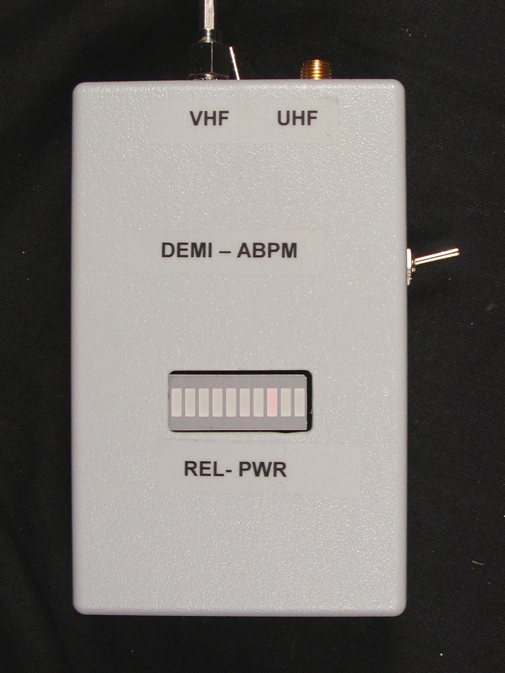
5 Enclosure assembly: the completed board photo is shown in step four above. Wires are added according to the Wire Assembly Table, ending up with the board wired to the bottom half of the enclosure like this: Finally, slip the board into the top half of the enclosure and screw it down. It might look like this last photo. Put the enclosure together, but hold it together with a rubber band for now the trimpots still need adjustment.
6 Calibration (from my previous paper) The frequency response of these detector chips is not flat; there is some variation with frequency, so any fine calibration must be at specific frequencies. For most purposes, however, relative calibration within a few db will suffice. Fig 8a: AD8307 Sensitivity Uncompensated Compensated 3 Output Voltage Power in dbm The two detectors have different sensitivity curves, shown in Figure 8. The AD8307 output is a straight line from about 70 dbm to about +5 dbm, a much greater dynamic range than any commercial power meter. Fig 8b: LTC5508 Sensitivity Output in millivolts Power in dbm
7 The straight line response of the AD8307 means that we can read power differences directly, at 25 millivolts per db. The LTC5508 does not have a linear response, nor is it as sensitive, with a useful range of around 20 dbm to about +13 dbm, comparable to an HP432 meter. So we have a combination of great sensitivity on the lower-frequency side and great frequency response on the higher-frequency side. The bar graph indicator is handy as a quick, no thinking required, indicator. Many times, that s all you need. Since the sensitivity curves in Figure 8 are so different, some compromise is required for the LED bar graph to make sense for both detectors. The output of the AD8307 may be loaded down, by R5 in the schematic to adjust the slope of the response. I found that an 18K resistor gave similar full-scale readings for both detectors. I set the ZERO pot (VR2) so that the first bar on the high-frequency side is lit*, to provide a free pilot light, and set the FULL SCALE pot (VR1) to light at +10 dbm. Then I measured the response of both sides at 144 MHz, shown in this Table: BARS Low Frequency High Frequency 1-70 dbm dbm Of course, you are free to adjust the calibration pots however you choose. The LED indicator may be operated as a bargraph or as a series of dots, with only one LED on at time. Since each LED draws about 20 ma., battery life will be much longer in dot mode. The mode is selected by a jumper, J4, on the board. When you are satisfied with the adjusments, screw the case together and apply the labels. Then put it to work. One amusing test is how much power leaks through the closed door of a microwave oven. * In the kit unit, I had to change R6 to 100 ohms to get the first bar to light with no signal. One final option: if you would prefer higher sensitivity but don t need the full frequency range, an LTC5534 may be substituted at U1. This will provide roughly 60 db of range, but only up to about 3.5 GHz.
8
9
Portable RF Sniffer and Power Meter
 Portable RF Sniffer and Power Meter Paul Wade W1GHZ 2003, 2004 RF power meters are extremely useful instruments. Whether we are tuning up homebrew equipment, checking antenna VSWR, adjusting a linear amplifier,
Pacific Antenna Field Strength Indicator Kit
 Pacific Antenna Field Strength Indicator Kit Description The Field Strength Indicator kit from Pacific Antenna provides a visual way to monitor the presence and relative strength RF fields through the
How to solder SMD component on Awesome PCB or any other kind of PCB.
 How to solder SMD component on Awesome PCB or any other kind of PCB. Step by step tutorial, with no steps to skip. Step 1 - What do we need? Step 2 - Fixing PCB Step 3 - Preparing for soldering Step 4
Lighthouse Beginner s soldering kit
 Lighthouse Beginner s soldering kit Kit contains: 1 x 220 ohm resistor (Red, Red, Black) 1 x 82k ohm resistor (Grey, Red, Orange) 2 x 220k ohm resistors (Red, Red, Yellow) 2 x Diodes 1 x Power switch 1
Learn to Solder: Simon Says Stencil Kit Information & Instructions
 Learn to Solder: Simon Says Stencil Kit Information & Instructions This is considered an intermediate kit for people who have soldered through-hole components before and wish to learn how to reflow surface
PI & T Attenuators. Version This document is for printed circuit board version 0.0a for both the PI and T attenuators.
 PI & T Attenuators Version This document is for printed circuit board version 0.0a for both the PI and T attenuators. Overview & Features: The PI and T attenuators use 0805 resistors and for most values
Xkitz.com XLO-5CP Control Panel for Five Channel Color Light Organ
 Xkitz.com XLO-5CP Control Panel for Five Channel Color Light Organ Rev 1.15 An Optional accessory for the Xkitz XLO-5 or XLO-5DC 5 Channel Color Light Organs Introduction This kit contains all the electronics
SoftRock v5.0 Builder s Notes. December 12, Building a QSD Kit
 SoftRock v5.0 Builder s Notes December 12, 2005 Building a QSD Kit Be sure to use a grounded tip soldering iron in building the QSD board. The soldering iron needs to have a small tip, (0.05-0.1 inch diameter),
tinycylon Assembly Instructions Contents Written by Dale Wheat Version August 2016 Visit dalewheat.com for the latest update!
 tinycylon Assembly Instructions Written by Dale Wheat Version 2.1 10 August 2016 Visit dalewheat.com for the latest update! Contents Assembly Instructions...1 Contents...1 Introduction...2 Quick Start
SoftRock v6.0 Builder s Notes. May 22, 2006
 SoftRock v6.0 Builder s Notes May 22, 2006 Be sure to use a grounded tip soldering iron in building the v6.0 SoftRock circuit board. The soldering iron needs to have a small tip, (0.05-0.1 inch diameter),
SSRP LTC1746 Assembly Manual V0.1 Check the most recent version
 SSRP LTC1746 Assembly Manual V0.1 Check the most recent version http://oscar.dcarr.org/ssrp/hardware/ltc1746/ltc1746.php Introduction This manual details the general assembly process for the SSRP LTC1746
Elektor Construction Guide TAPIR
 Elektor Construction Guide TAPIR The TAPIR is a three-dimensional assembly. To ensure good access to all soldering points, we recommend assembling the kit exactly according to the described sequence. 1
High-Power Directional Couplers with Excellent Performance That You Can Build
 High-Power Directional Couplers with Excellent Performance That You Can Build Paul Wade W1GHZ 2010 w1ghz@arrl.net A directional coupler is used to sample the RF energy travelling in a transmission line
Assembly Instructions for the 1.5 Watt Amplifier Kit
 Assembly Instructions for the 1.5 Watt Amplifier Kit 1.) All of the small parts are attached to a sheet of paper indicating both their value and id. 2.) Leave the parts affixed to the paper until you are
SoftRock v6.0 Builder s Notes. April 6, 2006
 SoftRock v6.0 Builder s Notes April 6, 006 Be sure to use a grounded tip soldering iron in building the v6.0 SoftRock circuit board. The soldering iron needs to have a small tip, (0.05-0. inch diameter),
Guitarpedalkits.com Overdrive Pedal Build Instructions
 Page 1 Guitarpedalkits.com Overdrive Pedal Build Instructions Follow the instructions in this guide to build your very own DIY overdrive pedal from GuitarPedalKits.com. If you re a first time builder,
LED Field Strength Indicator Kit
 LED Field Strength Indicator Kit Description The Field Strength Indicator kit from Qrpkits.com provides a visual way to monitor RF fields through the brightness of an LED. It will respond to RF fields
Custom Front Panel Upgrade Instructions
 Custom Front Panel Upgrade Instructions Here are the directions for upgrading your SP-II to an SP-IIB, with a custom blackanodized front panel and engraved lettering. There are only forty SP-IIB s in existence
Installation tutorial for Console Customs Xbox 360 Dual Rapid fire Microchip for wired and wireless controllers (all versions)
") Installation tutorial for Console Customs Xbox 360 Dual Rapid fire Microchip for wired and wireless controllers (all versions) This tutorial is designed to aid you in installation of a console customs
Installation tutorial for Console Customs Xbox 360 Dual Rapid fire Microchip for wired and wireless controllers (all versions) This tutorial is designed to aid you in installation of a console customs
V6.2 SoftRock Lite Builder s Notes. November 17, 2006
 V6.2 SoftRock Lite Builder s Notes November 17, 2006 Be sure to use a grounded tip soldering iron in building the v6.2 SoftRock circuit board. The soldering iron needs to have a small tip, (0.05-0.1 inch
Blue Ring Tester Kit Assembly & User Manual
 Blue Ring Tester Kit Assembly & User Manual Alltronics LLC/AnaTek Instruments 2761 Scott Blvd, Santa Clara, CA, 95050, USA March 2015 Edition Tel: 408-778-3868, Fax: 408-778-2558, E mail : tech@alltronics.com
AR.Drone 2 - Main Board External Antenna Modification Procedure. Document Number: EAM Check back for updates.
 Document Number: EAM-20130303-2 Check back for updates. 3/22/2013 NOTE: Along with this mod procedure, you will also need to: 1. Remove the Main Board. Refer to the Main Board Removal Procedure 2. Adapt
Mono Amplifier. LM386 Headphone Amp
 Mono Amplifier LM386 Headphone Amp Layout On/Off Switch - cuts power to the circuit Mono Input Jack: use either L or R or solder together Schematic Step 1 - Parts List 1.) R1-10ohm Resistor - Brown Black
Assembly instructions for the CS-1 ChemShield
 Page 1 Of 6 Assembly instructions for the CS-1 ChemShield What is S.M.D SMD=Surface mount devices, like all the components does not have leads, but gets soldered onto flat solder pads. The CS-1 assembly
Starving Student II. Starving Student II. SS2 guide. Written By: 6L guides.diyaudio.com/ Page 1 of 24
 SS2 guide Written By: 6L6 2019 guides.diyaudio.com/ Page 1 of 24 INTRODUCTION This is a build guide for the hybrid headphone/pre-amplifier. You can buy a kit at the SSII product listing on the diyaudio
Installation tutorial for Console Customs Xbox Mode Dual Button (RFX-5B) Rapid fire Microchip for all Wired and Wireless controllers
 Rapid fire Microchip for all Wired and Wireless controllers") Installation tutorial for Console Customs Xbox 360 5-Mode Dual Button (RFX-5B) Rapid fire Microchip for all Wired and Wireless controllers This tutorial is designed to aid you in installation of a console
Installation tutorial for Console Customs Xbox 360 5-Mode Dual Button (RFX-5B) Rapid fire Microchip for all Wired and Wireless controllers This tutorial is designed to aid you in installation of a console
Telecaster Wiring Kits Please Read All Instructions Before Beginning. Tools you will need: Soldering tips: Removing Current Wiring: Step 1. Step 2.
 Telecaster Wiring Kits Please Read All Instructions Before Beginning. Tools you will need: Soldering Iron (35 watt preferably) Solder Wet Sponge Wire Clippers Wire Strippers 3/8 Drill Bit 5/32 Drill Bit
Assembly Instructions for the FRB FET FM 70 Watt Amp
 Assembly Instructions for the FRB FET FM 70 Watt Amp 1.) Orient the circuit board with the diagram 2.) Use a narrow chisel tip 25-30 watt soldering iron for assembly 3.) All the small parts are taped onto
Repairing your Porsche 928 Central Warning System (CWS) controller
 controller") Repairing your Porsche 928 Central Warning System (CWS) controller Disclaimer: This procedure is for a 1984 Porsche 928 S controller. Overview: Under the left foot pedal (dead pedal) of the Porsche 928
Repairing your Porsche 928 Central Warning System (CWS) controller Disclaimer: This procedure is for a 1984 Porsche 928 S controller. Overview: Under the left foot pedal (dead pedal) of the Porsche 928
Penrose Quantizer Assembly Guide
 Penrose Quantizer Assembly Guide Schematic and BOM The schematic can be found here: www.sonic-potions.com/public/penrosequantizerschematic.pdf The BOM is available at google docs: Link to BOM Prepare the
MICROGRANNY v2.1 - Assembly Guide
 last update: 9. 5. 2017 MICROGRANNY v2.1 - Assembly Guide bastl-instruments.com INTRODUCTION Welcome to the assembly guide for the MicroGranny kit. MicroGranny is a monophonic granular sampler by Bastl
Bill of Materials: General Purpose Alarm, Pulsed PART NO
 General Purpose Alarm, Pulsed PART NO. 2190207 I hate alarms that sound continuously - unless they are smoke alarms. Smoke alarms should be annoying, but others should not. I wanted an alarm for a function
STEADY HAND GAME WITH LATCHING LED
 ESSENTIAL INFORMATION BUILD INSTRUCTIONS CHECKING YOUR PCB & FAULT-FINDING MECHANICAL DETAILS HOW THE KIT WORKS TEST YOUR HAND-EYE COORDINATION WITH THIS STEADY HAND GAME WITH LATCHING LED Version 2.0
Altoids Tin Filters. Paul Wade W1GHZ 2014
 Altoids Tin Filters Paul Wade W1GHZ 2014 w1ghz@arrl.net Several years ago, I described a series of "Multiband Microwave Transverters for the Rover - Simple and Cheap " (www.w1ghz.org), with several later
Value Location Qty Potentiometers C1M Distortion 1 A10k Volume 1. Footswitch 3PDT SW1 1. Jacks 1/4 Mono 2 DC Power 1
 Distortion BUILD INSTRUCTIONS Thank you for your purchase of our Distortion+ kit! We have completely redesigned our entire line of kits to be the most user friendly, while still maintaining their same
ArduTouch Music Synthesizer
 ArduTouch Music Synthesizer Assembly Instructions rev C Learn To Solder download for free at: http://mightyohm.com/soldercomic The following photos will show you how to solder. But feel free to download
Pacific Antenna Low Pass Filter Kit
 Pacific Antenna Low Pass Filter Kit Description Many basic transmitter and/or transceiver designs have minimal filtering on their output and frequently have significant harmonic content in their signals.
The ability to make basic voltage and resistance measurements using a digital multimeter
 Congratulations on your purchase of a new OneShot chassis! The PC01 OneShot combines a rugged enclosure, power supply, and discrete instrument DI in a compact 1/4U package. A few minutes of assembly are
A Deluxe LED Blinky That You Can Build!
 Lux Spectralis A Deluxe LED Blinky That You Can Build! Assembly Instructions Contents Step 1: Parts check... 2 Step 2: Tool check... 3 Step 3: Install the computer chip... 3 Step 4: Install the resistors...
DEM Part Number L144-28INTCK 144 MHz Transverter Kit and complete kit
 DEM Part Number L144-28INTCK 144 MHz Transverter Kit and complete kit Power Out: Noise Figure and Gain: DC Power Requirement: 50 mw linear minimum 3.5 db NF nominal, 5 dbg maximum 12-15.5 VDC, 13.8 nominal
Installation tutorial for Console Customs Xbox 360 MaxFire LITE rapid fire Mod Chip.
 Installation tutorial for Console Customs Xbox 360 MaxFire LITE rapid fire Mod Chip. This tutorial is designed to aid you in installation of a console customs MaxFire LITE modchip. This tutorial covers
QRPGuys Iambic Mini Paddle
 QRPGuys Iambic Mini Paddle First, familiarize yourself with the parts and check for all the components. If a part is missing, please contact us and we will send one. You must use qrpguys.parts@gmail.com
MEGAbitty Micro Line Sensor Board Assembly Instructions 11/15/2003
 1 Board Preparation U1 & U2 are mounted upside down, protruding through the board. That is, when the board is viewed from the top, the lenses should point down. Holes for U1 & U2 need to be cut out. Use
Any Questions? Contact us or Alligator Blinkie
 Alligator Blinkie The heart of this blinkie is a 12F1822 PIC produced by a company called Microchip. A PIC is a tiny, yet surprisingly powerful little computer. By itself, it can t do much it needs someway
Standard Kit #1 (3-way switch)
") Standard Kit #1 (3-way switch) Please Read All Instructions Before Beginning. Tools you will need: Soldering Iron (35 watt preferably) Solder Wet Sponge Wire Clippers 3/8 Drill Bit 1/4 Drill Bit Variable
Standard Kit #1 (3-way switch) Please Read All Instructions Before Beginning. Tools you will need: Soldering Iron (35 watt preferably) Solder Wet Sponge Wire Clippers 3/8 Drill Bit 1/4 Drill Bit Variable
Value Location Qty Transistors 2N5485 Q1, Q2, 4 Q3, Q4 2N5087 Q5 1. Trim Pots 250k VTRIM 1. Potentiometers C500k Speed 1. Toggle Switch On/On Vibe 1
 P-90 BUILD INSTRUCTIONS Thank you for your purchase of our P-90 kit! We have completely redesigned our entire line of kits to be the most user friendly, while still maintaining their same great sound!
The Walford Electronics Ford Receiver Kit Project Construction Manual
 The Walford Electronics Ford Receiver Kit Project Construction Manual Walford Electronics Ford Receiver construction manual V1.5 Page 1 of 22 Introduction The Ford receiver has four stages: The first stage
Ten Tec DDS Board Assembly Procedure
 05 May 2014 Ten Tec DDS Board Assembly Procedure You will find a photo of a completed board at the end of these instructions. Refer it whenever clarification is required. 1. AD9835 Attachment If you purchased
Pacific Antenna Easy SWR Indicator Kit
 Pacific Antenna Easy SWR Indicator Kit Description Monitoring the match of an antenna to your transmitter or adjusting an antenna tuner for best match requires an indicator of the reflected power as an
Hauptwerk Hardware Interface Board Kit for the Universal Midi Encoder Instruction Manual
 Hauptwerk Hardware Interface Board Kit for the Universal Midi Encoder Instruction Manual Hauptwerk Hardware 2016 Page 1 Release 1.2 February 2016 Table of Contents Introduction...3 Parts Identification...4
INSTALLATION INSTRUCTIONS
 XMOD 23 Mode Rapid Fire Mod Chip INSTALLATION INSTRUCTIONS This tutorial is designed to aid you in the installation of a XMOD Rapid Fire microchip. This installation requires soldering several wires to
Instructions for Lighting an S Scale Caboose
 Instructions for Lighting an S Scale Caboose The S Scale Caboose lighting kit is adaptable for most caboose models of rolling stock including American Flyer (TM) and contains the same components as found
DEM Part Number K, CK and LPK and CK 5.7 GHz. Transverter, Low Power Transverter, Kit and Complete Kit
 DEM Part Number 5760-144K, CK and 5760-144LPK and CK 5.7 GHz. Transverter, Low Power Transverter, Kit and Complete Kit Specifications Frequency: 5760.000 = 144.000 standard Noise Figure and Gain < 1.5
ABC V1.0 ASSEMBLY IMPORTANT!
 ABC V1.0 ASSEMBLY Before starting this kit, prepare the following tools: Soldering iron (15-20W will do), flush cutters, no.2 hex screwdriver or allen key and phillips screwdriver. Also briefly go through
OpenROV. Guide 3 - Electronics. We will now move to the assembly of the electronics that will control the ROV. Written By: OpenROV
 OpenROV Guide 3 - Electronics We will now move to the assembly of the electronics that will control the ROV. Written By: OpenROV 2017 openrov.dozuki.com Page 1 of 33 INTRODUCTION We will introduce soldering
Read This Page First
 Read This Page First If you are reading this you know the manuals are always available at QRPKITS.com. This is version 8.0 of the manual dated 4/27/2016. There is no need to print out the whole assembly
QLG1 GPS Receiver kit
 QLG1 GPS Receiver kit 1. Introduction Thank you for purchasing the QRP Labs QLG1 GPS Receiver kit. This kit will provide a highly sensitive, highly accurate GPS receiver module, using the popular MediaTek
4ms SCM Breakout. Kit Builder's Guide for PCB v2.1 4mspedals.com
 4ms SCM Breakout Kit Builder's Guide for PCB v2.1 4mspedals.com Shuffling Clock Multiplier Breakout This guide is for building a Shuffling Clock Multiplier Breakout module (SCMBO) version 2.1 from the
Construction Hints and Techniques
 Construction Hints and Techniques You just get finished building a Microwave project and it looks beautiful. After admiring it for awhile you decide to spark it up. All of the voltages and currents look
The Useless Machine. Parts Only - Build Guide v0001
 TM The Useless Machine Parts Only - Build Guide v0001 For the best outcome, follow each step in order. We recommend reading this guide entirely before you get started. Tools required: One phillips screwdriver,
Spiderbeam Balun Construction Guide
 BALUN CONSTRUCTION GUIDE Ver. 1.0 1 The components of the Balun Kit are in a plastic bag. Most of the components are inside the plastic case of the balun. The aluminum U-profile and the RG-142 Teflon Coax
Building the Sawdust Regenerative Receiver
 Building the Sawdust Regenerative Receiver Introduction The Sawdust is a super regenerative receiver using the basic Armstrong design architecture. The receiver uses one toroidal transformer to provide
Heartboard PCB Assembly Instructions
 Heartboard PCB Assembly Instructions Thanks for purchasing a Heartboard! These instructions will guide you through assembling and testing the Heartboard. Let s get started! Stuff you need Soldering iron
Building the Toothpick Audio CW Filter
 Building the Toothpick Audio CW Filter Introduction The toothpick is a simple variable bandpass audio filter designed to compliment the Splinter QRPp Trans-Receiver. The filter also contains an audio amplifier
DEM Part Number K, CK and LPK and CK 5.7 GHz. Transverter, Low Power Transverter, Kit and Complete Kit
 DEM Part Number 5760-144K, CK and 5760-144LPK and CK 5.7 GHz. Transverter, Low Power Transverter, Kit and Complete Kit Specifications Frequency: 5760.000 = 144.000 standard Noise Figure and Gain < 1.5
Line-Following Robot
 1 Line-Following Robot Printed Circuit Board Assembly Jeffrey La Favre October 5, 2014 After you have learned to solder, you are ready to start the assembly of your robot. The assembly will be divided
Executive Decision Maker Pro Assembly Guide
 Assembly Guide 1 Introduction Congratulations with acquiring your Executive Decision Make Pro. This guide attempts to follow you through the entire assembly process and should give you help to find order
Assembly Instructions
 Assembly Instructions For the SSQ-2F 3.1 MHz Rife Controller Board Kit v1.41 Manual v1.00 2012 by Ralph Hartwell Spectrotek Services GENERAL ASSEMBLY INSTRUCTIONS Arrange for a clean work surface with
DIODE / TRANSISTOR TESTER KIT
 DIODE / TRANSISTOR TESTER KIT MODEL DT-100K Assembly and Instruction Manual Elenco Electronics, Inc. Copyright 1988 Elenco Electronics, Inc. Revised 2002 REV-K 753110 DT-100 PARTS LIST If you are a student,
Pacific Antenna - Easy TR Switch
 Pacific Antenna - Easy TR Switch Kit Description The Easy TR Switch is an RF sensing switch that can be used to switch an antenna between a receiver and transmitter. It also has a second switched pair
STEP 0 Prepare the Materials.
 How to Build a Germanium Fuzz Guitar Effect. This document will guide you to build and test your Germanium Fuzz guitar pedal. With all the materials on hand, it takes around 2-4 hours to build it. Try
Any Questions? Contact us or BSA Atomic Blinkie
 BSA Atomic Blinkie The heart of this blinkie is a tiny electronic chip embedded in each of the three LEDs. When power is applied, the chip tells the LED to turn on and off, or fade different colors By
Simon Tilts Assembly Guide
 Page 1 of 20 Simon Tilts Assembly Guide Introduction Simon Tilts is a memory game very similar to Simon Says, but instead of pressing buttons, the player is challenged to rotate the device in a specific
S-Pixie QRP Kit. Student Manual. Revision V 1-0
 S-Pixie QRP Kit Student Manual Revision V 1-0 Introduction The Pixie 2 is a small, versatile radio transceiver that is very popular with QRP (low power) amateur radio operators the world over. It reflects
Pioneer Elite CLD-97 Digital Noise Reduction (DNR) Auto-off Mod DIY Installation Guide
 Auto-off Mod DIY Installation Guide") Pioneer Elite CLD-97 Digital Noise Reduction (DNR) Auto-off Mod DIY Installation Guide Background: The CLD-97 laserdisc player has one of the best video quality outputs of any laserdisc player released.
Pioneer Elite CLD-97 Digital Noise Reduction (DNR) Auto-off Mod DIY Installation Guide Background: The CLD-97 laserdisc player has one of the best video quality outputs of any laserdisc player released.
PRELIMINARY. ELECRAFT WM1 Power Meter. Assembly and Operating Manual. Introduction. Specifications. Tools Required. Parts List
 ELECRAFT WM1 Power Meter Assembly and Operating Manual E740100: Revision A1, September 25, 2006 Copyright 2006, Elecraft; All Rights Reserved Introduction The Elecraft WM1 is a versatile RF power and SWR
Installing the Onyx Heated Bed
 Installing the Onyx Heated Bed This short supplement will guide you through replacing the Phebe I heated bed on your Rostock MAX with the new Onyx heated bed. Your Onyx upgrade kit should include the following
BP-1A. Band-Pass variable filter continuous tuning from 3 to 30MHz. For analogue or software-defined receivers (SDR) Assembly manual
 Assembly manual") BP-1A Band-Pass variable filter continuous tuning from 3 to 30MHz. For analogue or software-defined receivers (SDR) Assembly manual Last updated: December 1, 2017 ea3gcy@gmail.com Updates and news at:
BP-1A Band-Pass variable filter continuous tuning from 3 to 30MHz. For analogue or software-defined receivers (SDR) Assembly manual Last updated: December 1, 2017 ea3gcy@gmail.com Updates and news at:
LITTLE NERD v1.1 Assembly Guide
 last update: 9. 3. 2016 LITTLE NERD v1.1 Assembly Guide bastl instruments.com INTRODUCTION This guide is for building Little Nerd module from Bastl Instruments. It is good to have basic soldering skills
Tips in Soldering. By Jesus Beltran. Team J (AKA J Crew) EEC 134AB, Professor Xiaoguang Liu UC Davis College of Engineering
 EEC 134AB, Professor Xiaoguang Liu UC Davis College of Engineering") Tips in Soldering By Jesus Beltran Team J (AKA J Crew) EEC 134AB, 2015 16 Professor Xiaoguang Liu UC Davis College of Engineering INTRODUCTION Basic soldering skills is a trait that every electronic/electrical
Tips in Soldering By Jesus Beltran Team J (AKA J Crew) EEC 134AB, 2015 16 Professor Xiaoguang Liu UC Davis College of Engineering INTRODUCTION Basic soldering skills is a trait that every electronic/electrical
Standard Kit #1 (5-way switch)
") Standard Kit #1 (5-way switch) Please Read All Instructions Before Beginning. Tools you will need: Soldering Iron (35 watt preferably) Solder Wet Sponge Wire Clippers 3/8 Drill Bit 1/4 Drill Bit Variable
Standard Kit #1 (5-way switch) Please Read All Instructions Before Beginning. Tools you will need: Soldering Iron (35 watt preferably) Solder Wet Sponge Wire Clippers 3/8 Drill Bit 1/4 Drill Bit Variable
Building the Sawdust Regenerative Receiver
 Building the Sawdust Regenerative Receiver Introduction The Sawdust is a super regenerative receiver using the basic Armstrong design architecture. The receiver uses one toroidal transformer to provide
Pacific Antenna Easy TR Switch
 Pacific Antenna Easy TR Switch Kit Description The Easy TR Switch is an RF sensing circuit with a double pole double throw relay that can be used to automatically switch an antenna between a separate receiver
Soldering Application
 Soldering Application Eugene Kim EEC 134 Team GrildurFrostcrag!1 I. Introduction Soldering, using fusible metal alloy as an adhesive, played a key role in constructing the quarter two RF radars. It is
FRONT PANEL ASSEMBLY
 2017-05-07 The Midnight Ultimate Keyer (MUK) consists of two functional assemblies: Rear Panel containing the interface and power connectors. Front Panel containing the basic keyer electronics, the four-character
Assembly Manual for VFO Board 2 August 2018
 Assembly Manual for VFO Board 2 August 2018 Parts list (Preliminary) Arduino 1 Arduino Pre-programmed 1 Faceplate Assorted Header Pins Full Board Rev A 10 104 capacitors 1 Rotary encode with switch 1 5-volt
QRPGuys Michigan Mighty Might Plus 40M Transmitter
 QRPGuys Michigan Mighty Might Plus 40M Transmitter First, familiarize yourself with the parts and check for all the components. If a part is missing, please contact us and we will send one. You must use
Programmable Timer Teaching Notes Issue 1.2
 Teaching Notes Issue 1.2 Product information: www.kitronik.co.uk/quicklinks/2121/ TEACHER Programmable Timer Index of sheets Introduction Schemes of work Answers The Design Process The Design Brief Investigation
RF Current Meter Kit
 Kit When assembled, this kit provides you with a simple but effective means of measuring the current in antenna wires, and of looking for braid currents on coax feeders. The more current you can get flowing
Ribcage Installation. Part 2 - Assembly. Back-Bone V1.06
 Ribcage Installation Part 2 - Assembly Back-Bone V1.06 Contents Section 1 Before You Get Started... 2 Included With Your Kit:... 2 Figure: A... 3 CAUTION!... 4 Note:... 4 Tools Required... 5 Section 2:
IR add-on module circuit board assembly - Jeffrey La Favre January 27, 2015
 IR add-on module circuit board assembly - Jeffrey La Favre January 27, 2015 1 2 For the main circuits of the line following robot you soldered electronic components on a printed circuit board (PCB). The
FM Wireless Microphone Kit Instructions for Assembly Page 1 of 5
 Instructions for Assembly Page 1 of 5 1. Find Resistor R1. Remove any tape that may be attached to the leads. Bend the leads as needed to insert Resistor R1 into the printed circuit board in the holes
Micro USB Lamp Kit TEACHING RESOURCES. Version 2.1 DESIGN A STYLISH LAMP WITH THIS
 TEACHING RESOURCES SCHEMES OF WORK DEVELOPING A SPECIFICATION COMPONENT FACTSHEETS HOW TO SOLDER GUIDE DESIGN A STYLISH LAMP WITH THIS Micro USB Lamp Kit Version 2.1 Index of Sheets TEACHING RESOURCES
Explorer Wiring Kit (assembled)
") Explorer Wiring Kit (assembled) For Vintage, Firestorm & Standard Series Please Read All Instructions Before Beginning. Tools you will need: Soldering Iron (35 watt preferably) Solder Wet Sponge Wire Clippers
Explorer Wiring Kit (assembled) For Vintage, Firestorm & Standard Series Please Read All Instructions Before Beginning. Tools you will need: Soldering Iron (35 watt preferably) Solder Wet Sponge Wire Clippers
DIODE / TRANSISTOR TESTER KIT
 DIODE / TRANSISTOR TESTER KIT MODEL DT-100K 99 Washington Street Melrose, MA 02176 Phone 781-665-1400 Toll Free 1-800-517-8431 Visit us at www.testequipmentdepot.com Assembly and Instruction Manual Elenco
Instructions for building the PGA432 70cm preamplifier
 Instructions for building the PGA432 70cm preamplifier Issue 0.2 17/11/16 First step Carefully place the PCB, track side up, inside the lid of the tinplate box. Ensure that the PCB is centrally located.
LED Infinity Mirror Controller, 32 LEDs, Multiple Patterns.
 http://wwwinstructablescom/id/led-infinity-mirror-controller-32-leds-multiple-/ Food Living Outside Play Technology Workshop LED Infinity Mirror Controller, 32 LEDs, Multiple Patterns by ChromationSystems
The Useless Machine. DIY Soldering Edition. Instruction Guide v0004
 The Useless Machine DIY Soldering Edition Instruction Guide v0004 TM For the best outcome, follow each step in order. We recommend reading this guide entirely before you get started. Tools required: Soldering
LPF-9B Nine band low pass filter module kit ( meters)
") LPF-9B Nine band low pass filter module kit (80-60-40-30-20-17-15-12-10 meters) Assembly manual Last update: March 1, 2018 ea3gcy@gmail.com Most recent updates and news at: www.ea3gcy.com Thanks for constructing
LPF-9B Nine band low pass filter module kit (80-60-40-30-20-17-15-12-10 meters) Assembly manual Last update: March 1, 2018 ea3gcy@gmail.com Most recent updates and news at: www.ea3gcy.com Thanks for constructing
C.M.HOWES COMMUNICATIONS CTU150 Instructions
 CTU150 Instructions The HOWES CTU150 is an antenna matching unit for use with shortwave transmitters and receivers. A novel constructional method is used - all parts being mounted on a Printed Circuit