MARTIN - G8JNJ ECLECTIC AETHER - ADVENTURES WITH AMATEUR RADIO
|
|
|
- Janis Stone
- 5 years ago
- Views:
Transcription
1 MARTIN - G8JNJ ECLECTIC AETHER - ADVENTURES WITH AMATEUR RADIO REDUCING RTL DONGLE INTERNAL SPURII AND NOISE SIGNALS I ve recently bought quite a few RTL DVB-T RTL 2832U / Rafael Micro R820T dongles to use for various purposes. Whilst experimenting with these devices, I ve noticed that one or two have much higher levels of internally generated unwanted signals and broadband noise than the others. Prodding around with a spectrum analyser I ve found that there are three main sources of internally generated noise. 1. Carriers at multiples of the 28MHz clock oscillator 2. Wideband noise with spurs from the USB data lines 3. Wideband noise with spurs from the on board 3.3v to 1.2v DC-DC convertor Plus received noise on the connecting cables which can be from any of the above, or external sources. Looking first at the three internally generated noises. The 28MHz oscillator is a fairly integral part of the design, so there s not a lot that can be done to reduce these signals. Soldering the oval shaped metal can of the crystal to the PCB ground plane can reduce the level of some harmonics slightly, but I found that any improvement was hardly noticeable. Wideband noise with spurs from the USB data lines and the on board 3.3v to 1.2v DC-DC convertor could be dramatically reduced by adding some metal screening around the RF input stage. I used some very thin brass sheet that I obtained from a model shop for this purpose, but some metal from a tin can would work just as well. I found that this was easier to implement if I removed the IR receiver, blue LED and associated surface mount resistors from the top side of the board. Adding a small patch of metal across the underside of the RF connector pins on the reverse side of the PCB also made a big difference. Note that placing the whole dongle inside a tin can didn't seem to help. The noise seems to be coupled directly between components on the topside of the PCB. I decided to try fitting 0.1uF chip caps across all the main electrolytic capacitors and DC rails. None of these seemed to make much of a difference to the remaining spurious signals that could be observed with the antenna disconnected, but I thought it was worth adding them for the sake of completeness.

2 If these modifications are done carefully, the plastic case will snap back on without any problems. All of these modifications made a significant reduction of unwanted signals. The next two photos show the before and after unwanted signal levels at around 480MHz. Note that these signal levels were with the dongle set for the maximum RF gain of 42dB. When used at a more reasonable gain setting of 30dB, all unwanted signals (with the exception of harmonics of the crystal oscillator) were usually at a level near or below the dongle noise floor. Before the modifications
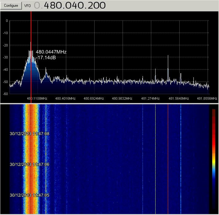
3 After the modifications

4 I also noticed that the 820 sticks have got a back to back SMD package strapped directly across the RF input. It may be worth checking to see if that has got popped by static if you have a broken one. Once I had sorted out the internal noise sources I took a look at what external factors could be causing problems. I noticed that when I connected the short RF fly-lead that was supplied with the dongle to the input, a lot of noises I d just got rid of had returned. These were not detectable when the input RF cable was removed. The main problem was the poorly screened fly-lead. Unfortunately the connector is a male MCX, which I didn't have in my junk box. So in the end I just ran a small length of thin PTFE 50 ohm coax with good screening from the rear of the connector to a BNC plug. A quick melt of the plastic case and the cable exits OK, and the case will fit back together again. Fortunately this solved the problem almost completely. I decided to cut up one of the dongle fly-leads in order to see if I could figure out why it was so problematic. As soon as I stripped back the coax and plastic moldings it was obvious that there was hardly any copper in the non-overlapped screen, and a very poor termination at the TV connector end.
.")
5 Fortunately it's easy to take apart the crimped connector at the MCX end and fit to some proper PTFE coax. So this is what I ve now done rather than wire directly to the board. In order to further improve the dongle screening and make them more robust. I made up this de-cast metal box for use on our uwave WEB SDR ( ebsdr.suw s.org.uk/). A photo of inside of box prior to fitting ferrite beads on the coax between the Dongle and a bulkhead RF connector., in order to help reduce the likelihood of RF current loops between coax screen and chassis. I had to characterise suitable ferrites for the best VHF / UHF choking impedance, as most clip-on types or similar don't do anything at these frequencies.


6 The USB screen needs a good low Z connection to the box metalwork and to the RF connector on the box. I found that if I didn't do this the screening was not as effective. Also any AC potential difference between the antenna coax and PC chassis resulted in current flow across the RTL PCB. This added multiple 50 / 100Hz noise sidebands to the LO. The type of USB connector I used was a chrome plated A to B bulkhead version from LCOM ECF504-BAS (

7 HF UP-CONVERTORS & RTL DONGLES I've been experimenting with an HF up-convertor and RTL DVB-T RTL 2832U / Rafael Micro R820T. The Up-convertor consisted of a 50MHz input low pass filter, high level double balanced mixer, 100MHz Local Oscillator and Output filter. Total conversion loss was approximately 7dB plus an additional 10dB attenuator on the output to reduce the signal level going into the dongle. I tested the up-convertor and dongle with a variety of antennas, including a 10m vertical, two different active antennas and a 100ft doublet with ATU. I measured the gain levels for different frequencies at which the dongle performed at the optimum performance in terms of S/N, dynamic range and low levels of IMD. I also made sure that there was enough headroom to cope with short duration increases in signal levels when operating at the optimum levels at different times of the day and night. I then averaged all the results and plotted them in Excel.
8 The shape of the general gain / frequency curves tend to remain fairly consistent between day and night. The only real difference is that the overall gain has to be reduced by abut 10dB at night to prevent overload at some frequencies between 5 and 15MHz. My thoughts are to build up a 3 section band notch filter with a center frequency just low of the Up-convertor LO frequency, so that I can obtain the required 30dB slope characteristic and use the dongle and up-convertor without having to change the gain setting every time I move frequency. Whilst experimenting I discovered that there was a major contest running and that 10m was wide open Here s a screen grab of the SDR Sharp spectrum display. A pretty impressive number of stations I think have you ever seen 10m so busy?

9 As part of this assessment I've also been testing to see if the limited dynamic range can provide adequate performance on the more crowded bands such as 7MHz. For these tests I have used a passive broadband vertical antenna in conjunction with an up-convertor and RTL820 dongle. I used SDR Sharp with various gain settings but no AGC selected. In order to find a worst case scenario with very high level signals I chose frequencies near the 9MHz AM broadcast band. First 12dB gain - note the level of noise floor relative to the maximum signals - looks clean with about 60dB dynamic range Notice the two diagonal traces from Ionospheric sounders gradually sweeping upwards in frequency.

10 21dB gain - note the rising level of noise floor relative to maximum signals - Start of severe intermodulation and reduction to 40dB dynamic range

11 34dB gain - note the very high level of noise floor in relation to maximum signals - very bad intermodulation products and only about 25dB dynamic range

12 Finally 44dB gain - note the levelling off of maximum signal levels and excessive intermodulation products

13 Here's another trace of the 7MHz amateur band with about 12dB of gain. No problems this time with intermodulation products, as the maximum signal levels are a lot lower than those from the AM broadcast stations on 9MHz.

14 Just to prove that I wasn't cheating with the above screen grab, here's a wider view of the night-time spectrum, with high power broadcast stations either side of the 40m amateur band.

15 I also performed some two tone IMD measurements on the RTL DVB-T RTL 2832U / Rafael Micro R820T dongle. The three screen grabs show in successive order. 1. 3rd order products with two carriers each at -3dB WRT 0dB reference line on SDR Sharp 2. As 1 but at 10dB higher level 2. As 1 but at 20dB higher level
16
17

18 I believe this demonstrates that if the SDR dongle gain is set appropriately, it s perfectly possible to use them for reception of the HF bands with a simple block up-convertor. Note that in all of the above cases I was feeding the block up-convertor directly from a large broadband antenna with no additional filtering. I have no doubt that the performance could be further improved by the addition of suitable band pass filters before the SDR dongle, if a greater dynamic range is desired on a particular band. Here s my suggestion of how to use multiple SDR dongles with a single HF up-convertor for a WEB SDR front end.
19 Please acknowledge the author if content is used elsewhere Martin Ehrenfried - G8JNJ 2007 to All content is made freely available for personal use only - Please contact me if you wish to make commercial use of any material
TS-930: Installing the Inrad Roofing Filter Mod
 TS-930: Installing the Inrad Roofing Filter Mod The TS-930 roofing filter mod consists of a 6 pole, 4 to 5 khz wide filter followed by a high dynamic range, feedback amplifier. The amplifier provides enough
TS-850: Installing the Inrad Roofing Filter Mod
 TS-850: Installing the Inrad Roofing Filter Mod The TS-850 Roofing Filter Mod consists of a 6 pole, 4 to 5 khz wide filter followed by a high dynamic range feedback amplifier. The amplifier provides enough
IC-781: Installing the Inrad Roofing Filter Mod
 IC-781: Installing the Inrad Roofing Filter Mod The Icom IC-781 roofing filter mod consists of a 6-pole, 4 to 5 khz wide filter followed by a high dynamic range, feedback amplifier. The amplifier provides
G0CWA Mk2 RTL SDR RADIO SEPTEMBER 2012
 G0CWA Mk2 RTL SDR RADIO SEPTEMBER 2012 For use with RTL2832U-based DVB-T USB dongle with the Elonics E4000 tuner Hi, welcome to my latest project my improved version of my SDR radio. This is based on my
The 144MHz Anglian 3 transverter
 The 144MHz Anglian 3 transverter A high performance 144/28MHz transverter G4DDK document issue 1 12/9/16 Introduction Anglian 3 is an update to the 144MHz Anglian 2 transverter. The Anglian 2 is no longer
The design of Ruthroff broadband voltage transformers M. Ehrenfried G8JNJ
 The design of Ruthroff broadband voltage transformers M. Ehrenfried G8JNJ Introduction I started investigating balun construction as a result of various observations I made whilst building HF antennas.
IC-765: Installing the Inrad Roofing Filter Mod
 IC-765: Installing the Inrad Roofing Filter Mod The Icom IC-765 roofing filter mod consists of a 6-pole, 4 khz wide filter followed by a high dynamic range, feedback amplifier. The amplifier provides enough
TS-870: Installing the Inrad Roofing Filter Mod
 TS-870: Installing the Inrad Roofing Filter Mod The TS-870 roofing filter mod consists of a 6 pole, 4 to 5 khz wide filter followed by a high dynamic range feedback amplifier. The amplifier provides enough
Alcatel White Box 24GHz Transceiver experiments and modifications
 Alcatel White Box 24GHz Transceiver experiments and modifications A set of working notes, measurements and comments PSU Need to supply : -5V up to ~ 30mA for Rx and PA modules +5.2V 1A for Rx and Tx mixer
PRC 320 Modifications Martin Ehrenfried G8JNJ
 PRC 320 Modifications Martin Ehrenfried G8JNJ I have deliberately not given specific cut wire here instructions, as the construction of the PRC320 does seem to vary considerably. This especially applies
N3ZI Kits General Coverage Receiver, Assembly & Operations Manual (For Jun 2011 PCB ) Version 3.33, Jan 2012
 Version 3.33, Jan 2012") N3ZI Kits General Coverage Receiver, Assembly & Operations Manual (For Jun 2011 PCB ) Version 3.33, Jan 2012 Thank you for purchasing my general coverage receiver kit. You can use the photo above as a
N3ZI Kits General Coverage Receiver, Assembly & Operations Manual (For Jun 2011 PCB ) Version 3.33, Jan 2012 Thank you for purchasing my general coverage receiver kit. You can use the photo above as a
A TRANSMISSION LINE BALANCE TEST METER
 by Lloyd Butler VK5BR with modifications by Phil Storr VK5SRP. Here is a simple meter to check the balance of currents running in the two legs of a transmission line. It can be used to check the balance
HF Receivers, Part 2
 HF Receivers, Part 2 Superhet building blocks: AM, SSB/CW, FM receivers Adam Farson VA7OJ View an excellent tutorial on receivers NSARC HF Operators HF Receivers 2 1 The RF Amplifier (Preamp)! Typical
A 40m Direct Conversion Receiver project to upgrade from ZR to ZS
 A 40m Direct Conversion Receiver project to upgrade from ZR to ZS Hannes Coetzee, ZS6BZP, B.Eng Elektronic (Pretoria) A simple receiver with a low component count is described for the 40m Amateur band.
TS-950: Installing the Roofing Filter Mod
 TS-950: Installing the Roofing Filter Mod The Kenwood TS-950 Roofing Filter Mod consists of a 6 pole, 4 to 5 khz wide filter followed by a high dynamic range feedback amplifier. The amplifier provides
by Cliff Pulis, KE0CP SDR Presentation - Cliff Pulis, KE0CP 1
 by Cliff Pulis, KE0CP SDR Presentation - Cliff Pulis, KE0CP 1 Basic Receiver Principles Mixing Frequencies Hetrodyn ing The IF Amplifier SDR Principles & Quadrature Phase (IQ) VHF / UHF DVB-T Dongle SDR
144MHz direct conversion receiver with I/Q outputs for use with Software Defined Radio.
 144MHz direct conversion receiver with I/Q outputs for use with Software Defined Radio. Overview This design is a direct conversion receiver for 144MHz with quadrature outputs for use either with a software
HF Amateur SSB Receiver
 HF Amateur SSB Receiver PCB Set for radio club project http://rhelectronics.net PCB for DIY HF Amateur SSB Receiver 20M The receiver is a simple syperheterodyne type with quartz crystal filter. The circuit
INTERNATIONAL RADIO CORP
 I N R A D INTERNATIONAL RADIO CORP 13620 Tyee Road Umpqua, OR 97486 (541) 459-5623 fax (541) 459 5632 E-mail: inrad@rosenet.net www.qth.com/inrad IC-775 ROOFING FILTER INSTALLATION INSTRUCTIONS The IC-775
Single Conversion LF Upconverter Andy Talbot G4JNT Jan 2009
 Single Conversion LF Upconverter Andy Talbot G4JNT Jan 2009 Mark 2 Version Oct 2010, see Appendix, Page 8 This upconverter is designed to directly translate the output from a soundcard from a PC running
G6ALU 20W FET PA Construction Information
 G6ALU 20W FET PA Construction Information The requirement This amplifier was designed specifically to complement the Pic-A-Star transceiver developed by Peter Rhodes G3XJP. From the band pass filter an
Using Ferrite Beads Keep RF Out of TV Sets, Telephones, VCR's Burglar Alarms and other Electronic Equipment
 Using Ferrite Beads Keep RF Out of TV Sets, Telephones, VCR's Burglar Alarms and other Electronic Equipment RFI and TVI have been with us for a long time. Now we have microwave ovens, VCR's and many other
MODIFICATION PROCEDURE
 Modifying the PRC174 to operate on 160m To modify the PRC174 to transmit on 160m involves 3 small changes. Total part count is 3 components a small signal transistor, a resistor and a capacitor. The normally
High-Power Directional Couplers with Excellent Performance That You Can Build
 High-Power Directional Couplers with Excellent Performance That You Can Build Paul Wade W1GHZ 2010 w1ghz@arrl.net A directional coupler is used to sample the RF energy travelling in a transmission line
huprf Panoramic Adaptor Installation FT847
 huprf Panoramic Adaptor Installation FT847 These instructions cover installation of the PAT board in the 1st IF of the FT847 45.705MHz this gives access to all receiver options on the main receiver. A
Technical Notes from Laplace Instruments Ltd. EMC Emissions measurement. Pre selectors... what, why and when?
 Technical Notes from Laplace Instruments Ltd EMC Emissions measurement. Pre selectors... what, why and when? Most of us working in EMC will have heard comments about pre-selectors. This article sets out
75 Meter SSB Project Design by KD1JV Built by Paul Jorgenson KE7HR NSS 39382FE
 75 Meter SSB Project Design by KD1JV Built by Paul Jorgenson KE7HR NSS 39382FE After completing a 75 meter DSB project (and using it underground, caving), I wanted to try building a SSB rig. I was searching
Technical Bulletin A Versatile Pulse Tester Page 1 of 6
 Technical Bulletin A Versatile Pulse Tester Page 1 of 6 A Versatile Pulse Tester By G8MNY (BATC's CQTV No 195, Updated Oct 07) (8 Bit ASCII Graphics use code page 437 or 850) This tester based on ideas
Radio Receivers. Al Penney VO1NO
 Radio Receivers Role of the Receiver The Antenna must capture the radio wave. The desired frequency must be selected from all the EM waves captured by the antenna. The selected signal is usually very weak
Alignment and Operation
 Introduction Spectrum Analyser theory Construction Techniques Power Supply Sweep Generator Logarithmic Amplifier 145 MHz IF Filter 1st Mixer 2nd Mixer 8 MHz IF Filter Low-pass Filter Input Attenuator 10MHz
Modifying The Heath HA-14 For 6 Meters Greg Chartrand - W7MY 4/22/07
 Introduction The Heathkit HA-14 was one of the few electron tube linear amplifiers intended for mobile use but few were purchased with the 12 volt mobile power supply. Most hams bought the HA-14 for base
Improving the Performance of the KSB2
 Introduction Improving the Performance of the KSB2 John Grebenkemper, KI6WX KI6WX@pacbell.net July 18, 2002 The following is a set of changes that I have done to my KSB2 and related circuits to improve
Sixty Meter Operation with Modified Radios
 Sixty Meter Operation with Modified Radios The following pages document the results of 6-meter transmitter performance on a group of transceivers that have been modified to enable operation on the sixty-meter
Modification of Alcatel 9400UX Synthesisers By Roger Ray G8CUB - Updated
 Modification of Alcatel 9400UX Synthesisers By Roger Ray G8CUB - Updated Many Alcatel Outdoor Units have been purchased, for conversion to 24GHz. For some reason the synthesiser local oscillator is not
Improving the ADF5355 synthesizer board (Version with Touch-Display)
") Improving the ADF5355 synthesizer board (Version with Touch-Display) Hello, Matthias, DD1US, March 24 th 2018, rev 1.1 Searching for a way to extend the frequency range of my test equipment I decided to
Improving the ADF5355 synthesizer board (Version with Touch-Display) Hello, Matthias, DD1US, March 24 th 2018, rev 1.1 Searching for a way to extend the frequency range of my test equipment I decided to
RF Current Meter Kit
 Kit When assembled, this kit provides you with a simple but effective means of measuring the current in antenna wires, and of looking for braid currents on coax feeders. The more current you can get flowing
The Uniden Grant XL Owners Site
 The Uniden Grant XL Owners Site Modifications page for the Grant XL (For Informational purposes only) The author of this site takes NO responsibility for illegal modifications and/or use of illegally modified
The RTL-SDR.com 2.6MHz HPF Broadcast AM Reject Filter. By D. B. Gain
 The RTL-SDR.com 2.6MHz HPF Broadcast AM Reject Filter By D. B. Gain The fine folks at RTL-SDR.com keep designing and releasing to market interesting, effective, and inexpensive doodads to aid the radio
HAMTRONICS TB901 FM EXCITER INSTALLATION, OPERATION, & MAINTENANCE
 HAMTRONICS TB901 FM EXCITER INSTALLATION, OPERATION, & MAINTENANCE GENERAL INFORMATION. The TB901 is a single-channel low power fm transmitter (exciter) designed to provide 300-600 milliwatts continuous
Assembly Instructions for the FRB FET FM 70 Watt Amp
 Assembly Instructions for the FRB FET FM 70 Watt Amp 1.) Orient the circuit board with the diagram 2.) Use a narrow chisel tip 25-30 watt soldering iron for assembly 3.) All the small parts are taped onto
Interference & Suppression Page 59
 INTERFERENCE Interference & Suppression Page 59 Front-End Overload, Cross-Modulation What is meant by receiver overload? Interference caused by strong signals from a nearby transmitter What is one way
DC Injector (Bias Tee) kit. Technical Manual
 kit. Technical Manual") DC Injector (Bias Tee) kit Technical Manual Document Author Dave Powis, G4HUP Date 7 Jan 2017 Version Issue 2_0 Document Ref HUP-05-020 http://huprf.com Tel +44 (0)1473 737717 g4hup@outlook.com Contents
DC Injector (Bias Tee) kit Technical Manual Document Author Dave Powis, G4HUP Date 7 Jan 2017 Version Issue 2_0 Document Ref HUP-05-020 http://huprf.com Tel +44 (0)1473 737717 g4hup@outlook.com Contents
Mobile TV Standard Antenna
 Mobile TV Standard Antenna Mads Sager Antenna Technology Manager Commercial Products Division Template 2.2 With built-in plug-and-play functionality, Molex s Mobile TV Standard Antenna integrates LDS technology
The water-bed and the leaky bucket
 The water-bed and the leaky bucket Tim Williams Elmac Services Wareham, UK timw@elmac.co.uk Abstract The common situation of EMC mitigation measures having the opposite effect from what was intended, is
A SDR-based receiver for Es hail-2 and the BACAR 6, 10 GHz beacons 30 July 2018
 A SDR-based receiver for Es hail-2 and the BACAR 6, 10 GHz beacons 30 July 2018 Hannes Coetzee, ZS6BZP Introduction If all goes according to plan the Qatar Satellite Company (Es hailsat) will place its
Building and Operating: LF Converter An SA612 based LF up-converter from Jackson Harbor Press
 Introduction: Building and Operating: LF Converter An SA612 based LF up-converter from Jackson Harbor Press The frequencies below the broadcast band are covered by few receivers on the market - those that
Directional Couplers / SWR detectors for 145MHz - 435MHz. Easily and cheaply made. pa0nhc. Ver. E4;
 1 of 9 12/1/2008 9:46 PM
DRM Receive Conversion for Yaesu FT920 HF Transceiver by Don M0DKS
 1. Introduction This conversion describes the addition of the DRM receive function for a Yaesu FT920 HF Transceiver that is equipped with the FM-1 optional FM transceive board. The FT920 is a double hetrodyne
V6.2 SoftRock Lite Builder s Notes. November 17, 2006
 V6.2 SoftRock Lite Builder s Notes November 17, 2006 Be sure to use a grounded tip soldering iron in building the v6.2 SoftRock circuit board. The soldering iron needs to have a small tip, (0.05-0.1 inch
Quadrature Upconverter for Optical Comms subcarrier generation
 Quadrature Upconverter for Optical Comms subcarrier generation Andy Talbot G4JNT 2011-07-27 Basic Design Overview This source is designed for upconverting a baseband I/Q source such as from SDR transmitter
20m G4BUD Mobile Whip
 This particular antenna was built specifically to take on holiday to Fuerteventura in the Canary Islands, after it was originally tested from an inland site in the UK. Amongst my first contacts using the
Yana Dongles Tom Berger K1TRB (c)2016 v171227
2016 v171227") Yana Dongles Tom Berger K1TRB (c)2016 v171227 These notes elaborate some items described in the Build notes, and add some more dongles enhancing Yana. Every effort has been exerted to save on the cost
Yana Dongles Tom Berger K1TRB (c)2016 v171227 These notes elaborate some items described in the Build notes, and add some more dongles enhancing Yana. Every effort has been exerted to save on the cost
How to use your antenna tuner.
 How to use your antenna tuner. There's more to it than what is in your manual or on most how to do it websites! http://www.arrl.org/tis/info/ant-tuner-op.html Here is a neat site with a "T" network simulator.
Modifying the Larcan VHF Lo/Hi 1.5KW Amplifier for 144MHz. by Corey Abercrombie, N4NGZ May 2015
 Modifying the Larcan VHF Lo/Hi 1.5KW Amplifier for 144MHz. by Corey Abercrombie, N4NGZ May 2015 This document details the steps I took to modify the Larcan VHF Lo/Hi 1.5KW Amplifier for 144MHz. With a
SPECIFICATIONS: Subcarrier Frequency 5.5MHz adjustable, FM Modulated +/- 50KHz. 2nd 11MHz >40dB down from 5.5MHz
 Mini-kits AUDIO / SUBCARRIER KIT EME75 Version4 SPECIFICATIONS: Subcarrier Frequency 5.5MHz adjustable, FM Modulated +/- 50KHz Subcarrier Output 1.5v p-p Output @ 5.5MHz DESCRIPTION & FEATURES: The Notes
A Compact Active Wide-Band Receiving Antenna [Part 1] Report by Derek G3GRO
![A Compact Active Wide-Band Receiving Antenna [Part 1] Report by Derek G3GRO](/thumbs/88/115261937.jpg "A Compact Active Wide-Band Receiving Antenna [Part 1] Report by Derek G3GRO") efficiency and assessing your abilities as an operator. You don t have to be up there among the high scoring big-guns to have some fun, but if your are a regular contender in a particular annual contest
efficiency and assessing your abilities as an operator. You don t have to be up there among the high scoring big-guns to have some fun, but if your are a regular contender in a particular annual contest
The ROSE 80 CW Transceiver (Part 1 of 3)
") Build a 5 watt, 80 meter QRP CW Transceiver!!! Page 1 of 10 The ROSE 80 CW Transceiver (Part 1 of 3) Build a 5 watt, 80 meter QRP CW Transceiver!!! (Designed by N1HFX) A great deal of interest has been
Build a 5 watt, 80 meter QRP CW Transceiver!!! Page 1 of 10 The ROSE 80 CW Transceiver (Part 1 of 3) Build a 5 watt, 80 meter QRP CW Transceiver!!! (Designed by N1HFX) A great deal of interest has been
Preliminary features of the SDR-X receiver SDR-X , PowerSDR Winrad Winrad DDS SFDR SFDR AD995 AD99 1
 Preliminary features of the SDR-X receiver The SDR-X receiver, in its full version is capable of continuously tuning the entire HF spectrum, 6m ( 50-52 MHz) band included. SSB, AM etc. demodulation, bandpass
CAVITY TUNING. July written by Gary Moore Telewave, Inc. 660 Giguere Court, San Jose, CA Phone:
 CAVITY TUNING July 2017 -written by Gary Moore Telewave, Inc 660 Giguere Court, San Jose, CA 95133 Phone: 408-929-4400 1 P a g e Introduction Resonant coaxial cavities are the building blocks of modern
Radio Receivers. Al Penney VO1NO
 Radio Receivers Al Penney VO1NO Role of the Receiver The Antenna must capture the radio wave. The desired frequency must be selected from all the EM waves captured by the antenna. The selected signal is
Construction Manual 4m-Linear-Transverter XV4-15
 Construction Manual 4m-Linear-Transverter XV4-15 Holger Eckardt DF2FQ Kirchstockacherstr. 33 D-85662 Hohenbrunn 3207 Technical data exciter frequency: 21.0... 21.5 MHz RF frequency: 70.0.. 70.5 MHz supply
Improved Ionospheric Propagation With Polarization Diversity, Using A Dual Feedpoint Cubical Quad Loop
 Improved Ionospheric Propagation With Polarization Diversity, Using A Dual Feedpoint Cubical Quad Loop by George Pritchard - AB2KC ab2kc@optonline.net Introduction This Quad antenna project covers a practical
12kHz LIF Converter V2.43 9Mhz version
 12kHz LIF Converter V2.43 9Mhz version Please Note: This document supersedes all previously released documents and drawings on the LIF subject. This is the latest and most up-to-date document at this time.
One I had narrowed the options down, I installed some wire and started testing.
 Loft & Attic antennas for restricted spaces - M. Ehrenfried G8JNJ I ve recently been looking at designs for an efficient antenna that would fit in a loft. I hoped to find something that would work on with
Beta-test ED1 PCB installed in I0CG s K1
 K1 SSB Modification (Ed.2) This description provides the receiver (RX) modifications, assembly, alignment and operation as a first step. In a second step you can add the remaining transmitter (TX) modifications,
VHF/UHF Dual Band J-Pole. By: Ed Fong WB6IQN
 VHF/UHF Dual Band J-Pole By: Ed Fong WB6IQN email: edison_fong@hotmail.com ARRL VHF/UHF Antenna Classics ARRL Vol. 8 Antenna Compendium ARRL Vol. 3 Antenna Compendium QST March 2007 QST February 2003 QST
Modification Details.
 Front end receiver modification for DRM: AKD Target Communications receiver. Model HF3. Summary. The receiver was modified and capable of receiving DRM, but performance was limited by the phase noise from
Tuning a 160M full sized vertical with strong AM broadcast RF present on the antenna. Jay Terleski, WX0B
 Tuning a 160M full sized vertical with strong AM broadcast RF present on the antenna. Jay Terleski, WX0B I often get asked about how to match a ¼ WL vertical to a 50 ohm transmission line and what to do
SWR myths and mysteries.
 SWR myths and mysteries. By Andrew Barron ZL3DW September 2012 This article will explain some of the often misunderstood facts about antenna SWR at HF and uncover some popular misconceptions. The questions
Modification of USB Sound Card for Asterisk app_rpt Use
 Modification of USB Sound Card for Asterisk app_rpt Use First off a huge thank you to Steve for providing the original notes on how to modify a USB sound card. (http://images.qrvc.com/usbfob.pdf) These
PN9000 PULSED CARRIER MEASUREMENTS
 The specialist of Phase noise Measurements PN9000 PULSED CARRIER MEASUREMENTS Carrier frequency: 2.7 GHz - PRF: 5 khz Duty cycle: 1% Page 1 / 12 Introduction When measuring a pulse modulated signal the
Pacific Antenna Low Pass Filter Kit
 Pacific Antenna Low Pass Filter Kit Description Many basic transmitter and/or transceiver designs have minimal filtering on their output and frequently have significant harmonic content in their signals.
4 Antennas as an essential part of any radio station
 4 Antennas as an essential part of any radio station 4.1 Choosing an antenna Communicators quickly learn two antenna truths: Any antenna is better than no antenna. Time, effort and money invested in the
SoftRock v6.0 Builder s Notes. May 22, 2006
 SoftRock v6.0 Builder s Notes May 22, 2006 Be sure to use a grounded tip soldering iron in building the v6.0 SoftRock circuit board. The soldering iron needs to have a small tip, (0.05-0.1 inch diameter),
An Introduction to Radio Frequency Interference
 An Introduction to Radio Frequency Interference Ron Hranac, N0IVN Member, ARRL EMC Committee ARRL Colorado Section Technical Specialist What is RFI? RFI is an abbreviation for radio frequency interference
MC-1612 Hardware Design Guide
 LOCOSYS Technology Inc. MC-1612 Hardware Design Guide Version 1.0 Date: 2013/09/17 LOCOSYS Technology Inc. 1 General Rules for Design-in In order to obtain good GPS performances, there are some rules which
PCB Design Guidelines for GPS chipset designs. Section 1. Section 2. Section 3. Section 4. Section 5
 PCB Design Guidelines for GPS chipset designs The main sections of this white paper are laid out follows: Section 1 Introduction Section 2 RF Design Issues Section 3 Sirf Receiver layout guidelines Section
1 MHz 6 GHz RF Mixer with built in PLL Synthesizer
 Windfreak Technologies Preliminary Data Sheet v0.1a MixNV Active Mixer v1.4a $499.00US 1 MHz 6 GHz RF Mixer with built in PLL Synthesizer Features Open source Labveiw GUI software control via USB Run hardware
The Design of A 125W L-Band GaN Power Amplifier
 Sheet Code RFi0613 White Paper The Design of A 125W L-Band GaN Power Amplifier This paper describes the design and evaluation of a single stage 125W L-Band GaN Power Amplifier using a low-cost packaged
Improving the immunity of sensitive analogue electronics
 Improving the immunity of sensitive analogue electronics T.P.Jarvis BSc CEng MIEE MIEEE, I.R.Marriott BEng, EMC Journal 1997 Introduction The art of good analogue electronics design has appeared to decline
A short, off-center fed dipole for 40 m and 20 m by Daniel Marks, KW4TI
 A short, off-center fed dipole for 40 m and 20 m by Daniel Marks, KW4TI Version 2017-Nov-7 Abstract: This antenna is a 20 to 25 foot long (6.0 m to 7.6 m) off-center fed dipole antenna for the 20 m and
Test Equipment. PHYS 401 Physics of Ham Radio
 Test Equipment Voltmeter - an instrument that is used to measure voltage. It is used in parallel with a circuit to be measured. a series resistor extends the range of the meter. Ammeter - an instrument
Modifying the RX320 Receiver for LF/VLF Operation
 Modifying the RX320 Receiver for LF/VLF Operation BACKGROUND The RX320 has gotten a lot of enthusiasm from users and reviewers for its cost vs. performance on the HF bands. It is rated down to 100 khz
DDS VFO 2 CONSTRUCTION MANUAL. DDS VFO 2 Construction Manual Issue 1 Page 1
 DDS VFO 2 CONSTRUCTION MANUAL DDS VFO 2 Construction Manual Issue 1 Page 1 Important Please read before starting assembly STATIC PRECAUTION The DDS VFO kit contains the following components which can be
Antenna Design for FM-02
 Antenna Design for FM-02 I recently received my FM-02 FM transmitter which I purchased from WLC. I researched the forum on what antennas where being used by the DIY community and found a nice write-up
Fun with Preamps A great way to pass a cold winter afternoon is to homebrew some preamps Designs and Benchmarks Construction The W7IUV Preamp
 Fun with Preamps A great way to pass a cold winter afternoon is to homebrew some preamps Built two preamps today. I ve been thinking of building a couple as a general interest project and today turned
Principles of Multicoupler Design 2009
 Multicouplers General A multicoupler is a device which connects a signal source to multiple units. The most common arrangement is for splitting a single antenna so that it can feed a number of receivers.
LNS ultra low phase noise Synthesizer 8 MHz to 18 GHz
 LNS ultra low phase noise Synthesizer 8 MHz to 18 GHz Datasheet The LNS is an easy to use 18 GHz synthesizer that exhibits outstanding phase noise and jitter performance in a 3U rack mountable chassis.
Rx antennas at IV3PRK: the 4-Square Rx Vertical Array
 Rx antennas at IV3PRK: the 4-Square Rx Vertical Array Part 2: putting all stuff together and construction details Calculating the cable lengths by Pierluigi Luis Mansutti IV3PRK The most difficult choice,
MC-1010 Hardware Design Guide
 MC-1010 Hardware Design Guide Version 1.0 Date: 2013/12/31 1 General Rules for Design-in In order to obtain good GPS performances, there are some rules which require attentions for using MC-1010 GPS module.
Assembly Instructions for the 1.5 Watt Amplifier Kit
 Assembly Instructions for the 1.5 Watt Amplifier Kit 1.) All of the small parts are attached to a sheet of paper indicating both their value and id. 2.) Leave the parts affixed to the paper until you are
Keysight Technologies Making Accurate Intermodulation Distortion Measurements with the PNA-X Network Analyzer, 10 MHz to 26.5 GHz
 Keysight Technologies Making Accurate Intermodulation Distortion Measurements with the PNA-X Network Analyzer, 10 MHz to 26.5 GHz Application Note Overview This application note describes accuracy considerations
Box Level Troubleshooting and Quick Look Engineering. Bruce C. Gabrielson PhD Security Engineering Services P.O. 550 Chesapeake Beach.
 Box Level Troubleshooting and Quick Look Engineering Bruce C. Gabrielson PhD Security Engineering Services P.O. 550 Chesapeake Beach., MD 20732 Abstract With costs and scheduling issues associated with
W4RT Electronics A Division of CyberAir Development Corporation 22 March For the Yaesu FT-817 & FT-817ND
 W4RT Electronics A Division of CyberAir Development Corporation www.w4rt.com 22 March 2005 For the Yaesu FT-817 & FT-817ND The ONE BOARD FILTER (OBF-817) is an accessory for the YAESU FT-817 and FT-817ND.
Foxhunt Offset Attenuator. Parts List:
 When your closing in on the fox you may find the signals to be so strong that you can no longer find a peak or null with your antenna. Sometimes the signal is so strong that the RF will leak straight into
The Amazing MFJ 269 Author Jack Tiley AD7FO
 The Amazing MFJ 269 Author Jack Tiley AD7FO ARRL Certified Emcomm and license class Instructor, Volunteer Examiner, EWA Technical Coordinator and President of the Inland Empire VHF Club What Can be Measured?
SoftRock v6.0 Builder s Notes. April 6, 2006
 SoftRock v6.0 Builder s Notes April 6, 006 Be sure to use a grounded tip soldering iron in building the v6.0 SoftRock circuit board. The soldering iron needs to have a small tip, (0.05-0. inch diameter),
HAMTRONICS R451 UHF FM RECEIVER: INSTALLATION, OPERATION, & MAINTENANCE
 HAMTRONICS R451 UHF FM RECEIVER: INSTALLATION, OPERATION, & MAINTENANCE FUNCTIONAL DESCRIPTION. The R451 is a premium, commercial- grade single-channel uhf fm receiver. It features a GaAs FET rf amplifier
Preamplifiers for Callisto Solar Radio Spectrometer
 Preamplifiers for Callisto Solar Radio Spectrometer Whitham Reeve and Christian Monstein 1. Introduction We investigated the performance of three amplifiers (figure 1) for Callisto applications by measuring
Radio Frequency Interference. ARRL Book Section 3.5
 Radio Frequency Interference ARRL Book Section 3.5 Interference Hearing something or signals getting where not suppose to Things like hearing the radio on your telephone or telephone calls on your TV Sometimes