TS-930: Installing the Inrad Roofing Filter Mod
|
|
|
- Cory Lawrence
- 5 years ago
- Views:
Transcription
1 TS-930: Installing the Inrad Roofing Filter Mod The TS-930 roofing filter mod consists of a 6 pole, 4 to 5 khz wide filter followed by a high dynamic range, feedback amplifier. The amplifier provides enough gain to override the filter insertion loss, plus an additional db or two. The plot below shows the sweep frequency response of the front end and first IF filter in a TS-930 radio. The wider curve is the OEM response and the narrow curve is with the Inrad roofing filter mod added. In the TS-930, the most important part of the roofing filter characteristic is from the pass band down about 35 or 40 db on each side. Ref MHz 5.00kHz/div Res bw 1kHz 2009 International Radio Corporation. Modifications are done at your own risk; seek assistance if you are not qualified to make these modifications. International Radio assumes no responsibility for any damages or injuries resulting from improper installation of this modification kit. Revised
2 The result of the bandwidth improvement shown above is the reduction of close in intermodulation from multiple signals. The IMD dynamic range will be improved 5 to 10 db for some signal spacings. The main receiver audio response will be reduced about 100 Hz in the SSB mode. Operating the noise blanker will not result in as much degradation of the dynamic range. 1. What can you expect from this mod? Less IMD in crowded band conditions, particularly from stations at offset frequencies of 2 to 10 khz on either side of the operating frequency. 2. Will it defeat the noise blanker? No, the roofing filter is in the circuit before the noise blanker sample is taken. The filter delay is added to both signal and noise. Since less noise and fewer strong signals are able to reach the noise blanker, it actually improves its operation. 3. Will this mod allow for wide band SSB, AM and FM reception? No, as the overall widest bandwidth of the receiver will be determined by the roofing filter, which is about 5 khz. Normal 2400 Hz SSB will not be affected. Description of Operation The Roofing filter mod inserts a narrow band crystal filter in between the RF assembly and the IF or Main board. An amplifier is included to compensate for the filter loss and to provide a small amount of excess gain. Reducing the bandwidth at this point in the radio helps to keep strong off-frequency signals out of the second mixer where they can cause intermodulation. The excess gain slightly improves the noise floor of the radio. During transmit operation the amplifier and filter are removed to allow the signal to pass in the other direction from the IF to the RF assembly. Installation Instructions Warning: Modern radios contain components that may be damaged by static discharge. Precautions must be taken to eliminate any static electricity buildup between the operator and the radio before any of the internal circuits are touched. If you are not familiar with the proper techniques for this, consult the Radio Amateurs Handbook International Radio Corporation
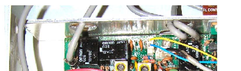
3 Note: If you have a known test signal available before you start, note the S meter reading. After the installation, the S meter should read the same. 1. Remove the AC line cord from the transceiver. 2. Remove both top and bottom covers. 3. Limited space on the bottom side of the radio makes installation of the roofing filter almost impossible. Because of this, the roofing filter will be mounted on the top side of the radio. There is space between the final unit and the antenna tuner. With the radio top side up and the front panel facing you, the final unit is the large shielded assembly in the right rear of the radio. If your radio has an antenna tuner installed, it is in front of the final unit towards the panel on the right side. The roofing filter will be mounted with double stick tape to the front surface of the final unit. See the photo. If your radio does not have the antenna tuner installed, you may use the plastic standoffs to mount the roofing filter. 4. Prepare the roofing filter for installation by soldering the red and black wires to the +12V and GND pads respectively. Insert the coax cables into J1 and J2. Be sure they are firmly seated because if they should come loose it will be very difficult to replace them after the mod is in place. Examine the solder side of the pc board. Make one of the cables to identify after they are pulled through to the bottom of the radio. Trim wire ends on the board down to the solder pads. Any protruding wires may short to the chassis. Apply the double stick tape to the solder side of the mod pc board. 5. Position the mod approximately in place and feed the four wires through the hole in the chassis near the right end of the chassis between the two assemblies. When you have the mod ready, remove the safety paper on the double stick tape and press it in its final position. See Figure Turn the radio over for access to the bottom side. With the front panel facing you, note the small sub assembly fastened to the left hand side of the chassis wall. This is the RF unit. Remove the four screws holding it in place. 7. Carefully turn it so that the coax cables connected to it become visible. Note the short coax coming from the front edge nearest the front panel. The marking says RIF or IF1, depending upon serial number, and it connects to the Signal Unit a short distance away which is marked RIF. Remove this cable International Radio Corporation


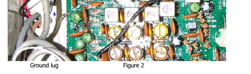
4 8. Insert the coax coming from J1 on the Inrad board into the RIF or IF1 connector on the RF unit. 9. Insert the coax coming from J2 on the Inrad board into the RIF connector on the Signal Unit. 10. Dress the two coax cables along the chassis underneath the shield so they will not interfere with the RF unit mounting. Replace the RF unit and fasten the four screws. 11. Strip 1/8 inch of insulation from the black wire. Solder to the ground lug near the RF Unit. Cut to fit if it is too long. See figure Strip ¼ inch of insulation from the red wire. Tin and form a hook on the end. Locate Jumper J87, and hook the red wire on the top of it. Solder. See Figure 2. This completes the installation. You may want to connect an antenna and test the radio to be sure you are receiving signals before reinstalling the covers International Radio Corporation

5 2009 International Radio Corporation
6 Parts List Modified Assembled Roofing Filter board (Inrad ) 2 Coax cables Double stick tape 2 Board mounts Red and black #24 wire International Radio Corporation
IC-765: Installing the Inrad Roofing Filter Mod
 IC-765: Installing the Inrad Roofing Filter Mod The Icom IC-765 roofing filter mod consists of a 6-pole, 4 khz wide filter followed by a high dynamic range, feedback amplifier. The amplifier provides enough
IC-781: Installing the Inrad Roofing Filter Mod
 IC-781: Installing the Inrad Roofing Filter Mod The Icom IC-781 roofing filter mod consists of a 6-pole, 4 to 5 khz wide filter followed by a high dynamic range, feedback amplifier. The amplifier provides
TS-950: Installing the Roofing Filter Mod
 TS-950: Installing the Roofing Filter Mod The Kenwood TS-950 Roofing Filter Mod consists of a 6 pole, 4 to 5 khz wide filter followed by a high dynamic range feedback amplifier. The amplifier provides
TS-870: Installing the Inrad Roofing Filter Mod
 TS-870: Installing the Inrad Roofing Filter Mod The TS-870 roofing filter mod consists of a 6 pole, 4 to 5 khz wide filter followed by a high dynamic range feedback amplifier. The amplifier provides enough
TS-850: Installing the Inrad Roofing Filter Mod
 TS-850: Installing the Inrad Roofing Filter Mod The TS-850 Roofing Filter Mod consists of a 6 pole, 4 to 5 khz wide filter followed by a high dynamic range feedback amplifier. The amplifier provides enough
INTERNATIONAL RADIO CORP
 I N R A D INTERNATIONAL RADIO CORP 13620 Tyee Road Umpqua, OR 97486 (541) 459-5623 fax (541) 459 5632 E-mail: inrad@rosenet.net www.qth.com/inrad IC-775 ROOFING FILTER INSTALLATION INSTRUCTIONS The IC-775
DRM Receive Conversion for Yaesu FT920 HF Transceiver by Don M0DKS
 1. Introduction This conversion describes the addition of the DRM receive function for a Yaesu FT920 HF Transceiver that is equipped with the FM-1 optional FM transceive board. The FT920 is a double hetrodyne
User Guide for the Alpha Loop Sr Antenna
 User Guide for the Alpha Loop Sr Antenna Manufactured by: Alpha Antenna 1.888.482.3249 Website: http://alphaantenna.com Available from: Amateur Radio Store Website: https://amateurradiostore.com User Guide
Ten-Tec Orion Sub Receiver VHF Filter Modification Prepared by Rick Williams, VE7TK
 Ten-Tec Orion Sub Receiver VHF Filter Modification Prepared by Rick Williams, VE7TK (Note: Those undertaking this modification do so at their own risk. The procedures outline a method of installing an
huprf Panoramic Adaptor Installation FT847
 huprf Panoramic Adaptor Installation FT847 These instructions cover installation of the PAT board in the 1st IF of the FT847 45.705MHz this gives access to all receiver options on the main receiver. A
C.M.HOWES COMMUNICATIONS CTU150 Instructions
 CTU150 Instructions The HOWES CTU150 is an antenna matching unit for use with shortwave transmitters and receivers. A novel constructional method is used - all parts being mounted on a Printed Circuit
HF Receivers, Part 2
 HF Receivers, Part 2 Superhet building blocks: AM, SSB/CW, FM receivers Adam Farson VA7OJ View an excellent tutorial on receivers NSARC HF Operators HF Receivers 2 1 The RF Amplifier (Preamp)! Typical
HT-1A Dual Band CW QRP Transceiver. Kit Building Instructions
 HT-A Dual Band CW QRP Transceiver Kit Building Instructions Rev B, July 8, 08 Designed by BD4RG Exclusively distributed by CRKITS.COM and its worldwide distributors Join the group http://groups.io/g/crkits
MARTIN - G8JNJ ECLECTIC AETHER - ADVENTURES WITH AMATEUR RADIO
 MARTIN - G8JNJ ECLECTIC AETHER - ADVENTURES WITH AMATEUR RADIO REDUCING RTL DONGLE INTERNAL SPURII AND NOISE SIGNALS I ve recently bought quite a few RTL DVB-T RTL 2832U / Rafael Micro R820T dongles to
Installation... 3 Installing The Radio... 3 Ignition Noise Interference... 4 Antenna... 4 External Speaker... 4 Public Address...
 TABLE OF CONTENTS CHAPTER 1 Specifications.............................................. 2 PAGE BIG RIG SERIES S 1 MOD PW R 20 0 3 SW R 40 1 5 5 60 1.5 7 10 2 9 20 80 3 30 +20 40 50 +40 100% MAX db +60
MPC-XU Universal Crossover
 MPC-U Universal Crossover For JBL MPC and MPA amplifiers Owner s Manual and Installation Guide I. Description The MPC-U is a dual-channel universal crossover filter accessory for use with JBL MPC and MPA
DEM Part Number L144-28INTCK 144 MHz Transverter Kit and complete kit
 DEM Part Number L144-28INTCK 144 MHz Transverter Kit and complete kit Power Out: Noise Figure and Gain: DC Power Requirement: 50 mw linear minimum 3.5 db NF nominal, 5 dbg maximum 12-15.5 VDC, 13.8 nominal
MODEL FS-4 INSTRUCTION MANUAL R.L. DRAKE COMPANY, MIAMISBURG, OHIO, U.S.A.
 MODEL FS-4 F R E Q U E N C Y S Y N T H E S I Z E R INSTRUCTION MANUAL R.L. DRAKE COMPANY, MIAMISBURG, OHIO, U.S.A. LIMITED WARRANTY R. L. DRAKE COMPANY warrants to the original purchaser that this product
Transceiver selection and Specs.
 Transceiver selection and Specs. Transceivers 1956-2018 From TUBES to SDR Covers 20-10 meters in 100Khz segments, 10 available, crystal needed for each. Plug in crystal holder. 100 Watts output, final
Yaesu FT-1000MP Mark V and NaP3
 Yaesu FT-1000MP Mark V and NaP3 This paper describes in detail the hardware and software required to implement a full-function panadaptor for the Mark V using NaP3. Illustration 1: Panadaptor in operation
Treetop Circuits Owner s Manual for SB-SB-600 Adapter Version 1
 The SB-600 SSB adapter from Treetop Circuits (Fig. 1) is designed specifically as an accessory to the Hammarlund SP-600 series of receivers. It provides enhanced performance on SSB and CW signals, using
Beta-test ED1 PCB installed in I0CG s K1
 K1 SSB Modification (Ed.2) This description provides the receiver (RX) modifications, assembly, alignment and operation as a first step. In a second step you can add the remaining transmitter (TX) modifications,
Improving the Performance of the KSB2
 Introduction Improving the Performance of the KSB2 John Grebenkemper, KI6WX KI6WX@pacbell.net July 18, 2002 The following is a set of changes that I have done to my KSB2 and related circuits to improve
Assembly Instructions for the 1.5 Watt Amplifier Kit
 Assembly Instructions for the 1.5 Watt Amplifier Kit 1.) All of the small parts are attached to a sheet of paper indicating both their value and id. 2.) Leave the parts affixed to the paper until you are
HW-8-TR V3 PARTS LIST
 HW-8-TR V3 PARTS LIST Qty Ref Description Markings 4C2 C3 C4 C5 Capacitor Disc.1ls.1uF 104 1 C1 Capacitor Disc.2ls.1uF 100V 104 1 QSKMOD-C92 Capacitor Electrolytic 1uF 50V 1 QSKMOD Capacitor Mylar.47uF
CLASS D MONO AMPLIFIER GM-D8601 GM-D9601. Owner s Manual
 CLASS D MONO AMPLIFIER GM-D8601 GM-D9601 Owner s Manual Before you start BE SURE TO OBSERVE THE FOLLOWING GUIDELINES:! Do not turn up the volume so high that you can t hear what s around you.! Use caution
BRIDGEABLE FOUR-CHANNEL POWER AMPLIFIER GM-A6604 GM-A4604. Owner s Manual
 BRIDGEABLE FOUR-CHANNEL POWER AMPLIFIER GM-A6604 GM-A4604 Owner s Manual Section 01 Before you start Thank you for purchasing this PIONEER product To ensure proper use, please read through this manual
DX 33HP. 10 Meter Amateur Mobile Transceiver OWNER S MANUAL. Download this Manual Free of Charge at
 DX 33HP SIG 1 3 TX PWR 5 7 9+30dB POWER HI NB/ANL MED LO HI LO BAND ECHO RX/TX VOL SQ MIC RF FM PA AM D/A E/B F/C ECHO TIME BAND 10 Meter Amateur Mobile Transceiver Download this Manual Free of Charge
A 75-Watt Transmitter for 3 Bands Simplified Shielding and Filtering for TVI BY DONALD H. MIX, W1TS ARRL Handbook 1953 and QST, October 1951
 A 75-Watt Transmitter for 3 Bands Simplified Shielding and Filtering for TVI BY DONALD H. MIX, W1TS ARRL Handbook 1953 and QST, October 1951 The transmitter shown in the photographs is a 3-stage 75-watt
Installation instructions, accessories. TV receiver, digital
 Installation instructions, accessories Instruction No 30756561 Version 1.1 5 Part. No. 30756181, 30756569 TV receiver, digital Volvo Car Corporation TV receiver, digital- 30756561 - V1.1 Page 1 / 36 Equipment
On-Line Cardio Theater Wireless Digital Transmitter Installation and Instruction Manual
 On-Line Cardio Theater Wireless Digital Transmitter Installation and Instruction Manual Full installation instructions accompany your Cardio Theater equipment order. This On-Line version of our Installation/Instruction
SUBELEMENT T4. Amateur radio practices and station set up. 2 Exam Questions - 2 Groups
 SUBELEMENT T4 Amateur radio practices and station set up 2 Exam Questions - 2 Groups 1 T4A Station setup: connecting microphones; reducing unwanted emissions; power source; connecting a computer; RF grounding;
HAMTRONICS TB901 FM EXCITER INSTALLATION, OPERATION, & MAINTENANCE
 HAMTRONICS TB901 FM EXCITER INSTALLATION, OPERATION, & MAINTENANCE GENERAL INFORMATION. The TB901 is a single-channel low power fm transmitter (exciter) designed to provide 300-600 milliwatts continuous
Test Equipment. PHYS 401 Physics of Ham Radio
 Test Equipment Voltmeter - an instrument that is used to measure voltage. It is used in parallel with a circuit to be measured. a series resistor extends the range of the meter. Ammeter - an instrument
Dual Band Filter Assembly Manual
 Dual Band Filter Assembly Manual 12 January 2018 Rev D Version Theory of Operation: The purpose of a Bandpass Filter is to filter out or reject all unwanted signals. The original KN-Q7A Receive Filter
G4HUP Panoramic Adaptor Installation FT1000MP
 G4HUP Panoramic Adaptor Installation FT1000MP These instruction cover installation of the PAT board in the 1st IF of the FT1000MP 70.455MHz this gives access to all receiver options on the main receiver.
English KS-DR3005D POWER AMPLIFIER: INSTRUCTION MANUAL
 KS-DR005D POWER AMPLIFIER: INSTRUCTION MANUAL B5E-009-00/00 [W] WARNING If the fuse blows, first make sure the wires aren t touching to cause a short circuit then replace the old fuse with one with the
Roofing Filters, Transmitted BW and Receiver Performance
 Roofing Filters, Transmitted BW and Receiver Performance Rob Sherwood NCØB What s important when it comes to choosing a radio? Sherwood Engineering Why Did I Start Testing Radios? Purchased a new Drake
TS-480 Replacing the standard MCF (monolithic crystal filter)
") TS-480 Replacing the standard MCF (monolithic crystal filter) The TS-480 has a monolithic crystal filter installed in the second IF (10,695 MHz). This is a 2,4 khz filter which is used on both RX and TX
TS-480 Replacing the standard MCF (monolithic crystal filter) The TS-480 has a monolithic crystal filter installed in the second IF (10,695 MHz). This is a 2,4 khz filter which is used on both RX and TX
E L E C R A F T K N B 1 N O I S E B L A N K E R
 Introduction E L E C R A F T K N B N O I S E B L A N K E R Assembly and Operating Instructions Revision C, Jan. 8, 200. Copyright 200, Elecraft; All Rights Reserved The KNB noise blanker can be used to
Cisco Aironet 13.5-dBi Yagi Mast Mount Antenna (AIR-ANT1949)
") Cisco Aironet 13.5-dBi Yagi Mast Mount Antenna (AIR-ANT1949) Overview This document describes the 13.5-dBi Yagi mast mount antenna and provides instructions for mounting it. The antenna operates in the
Cisco Aironet 13.5-dBi Yagi Mast Mount Antenna (AIR-ANT1949) Overview This document describes the 13.5-dBi Yagi mast mount antenna and provides instructions for mounting it. The antenna operates in the
1.0 General Description
 1.0 General Description Figure 1 - Plug-N-Play Noise Blanker for the Collins 75S-1 Series The Collins Noise Blanker is designed to be a Plug-N-Play accessory for the Collins 75S-1 series. The Noise Blanker
IC-756 Pro III vs. Pro II
 IC-756 Pro III vs. Pro II Improvements in the Pro III vs. the Pro II Adam Farson VA7OJ IC-756Pro3 Information & Links Copyright 2006 North Shore Amateur Radio Club NSARC HF Operators 756Pro3 vs. Pro2 1
ELECRAFT Application Note
 ELECRAFT Application Note Front Panel Microphone Circuit Modification Revision A, November 12, 2008 Copyright 2008, Elecraft, Inc., All Rights Reserved Background Some K3 owners have noted distorted transmit
Receiver Performance. Roofing Filters, Rob Sherwood NCØB. What s important when it comes to. choosing a radio? Sherwood Engineering
 Roofing Filters, Transmitted IMD and Receiver Performance Rob Sherwood NCØB What s important when it comes to choosing a radio? Sherwood Engineering 1 2 Why Did I Start Testing Radios? Purchased a new
Module 8 Theory. dbs AM Detector Ring Modulator Receiver Chain. Functional Blocks Parameters. IRTS Region 4
 Module 8 Theory dbs AM Detector Ring Modulator Receiver Chain Functional Blocks Parameters Decibel (db) The term db or decibel is a relative unit of measurement used frequently in electronic communications
Cisco Aironet 2.4-GHz/5-GHz 8-dBi Directional Antenna (AIR-ANT2588P3M-N)
") Cisco Aironet.4-GHz/5-GHz 8-dBi Directional Antenna (AIR-ANT588P3M-N) This document outlines the specifications for the Cisco Aironet AIR-ANT588P3M-N.4/5-GHz 8-dBi 3-Port Directional Antenna with N-connectors
Cisco Aironet.4-GHz/5-GHz 8-dBi Directional Antenna (AIR-ANT588P3M-N) This document outlines the specifications for the Cisco Aironet AIR-ANT588P3M-N.4/5-GHz 8-dBi 3-Port Directional Antenna with N-connectors
Roofing Filters, Transmitted BW and Receiver Performance
 Roofing Filters, Transmitted BW and Receiver Performance Rob Sherwood NCØ B What s important when it comes to choosing a radio? Sherwood Engineering Why Did I Start Testing Radios? Purchased a new Drake
POWER AMPLIFIER. Owner s Manual Mode d emploi Bedienungsanleitung Manual de instrucciónes CLIP SIGNAL TEMP PROTECTION POWER
 POWER AMPLIFIER Owner s Manual Mode d emploi Bedienungsanleitung Manual de instrucciónes TEMP PROTECTION POWER A CLIP SIGNAL B ON OFF M Introduction Thank you for purchasing a Yamaha C450/320/160 series
CONSTRUCTION. Refer to schematic and component location diagrams during assembly
 HAMTRONICS VHF RECEIVING CONVERTERS CONSTRUCTION, ALIGNMENT, & INSTALLATION INSTRUCTIONS GENERAL DESCRIPTION. The CA( ) series of VHF Receiving Converter modules are designed to amplify and convert the
Ambient Level Controller
 Ambient Level Controller Installation and Use Manual Issue 1, October 1999 1999 Bogen Communications, Inc. All rights reserved. 54-2028-01 9910 Model: LUALC PEC Code: 5335-621 COM Code: 408184273 Select
INSTALLATION INSTRUCTIONS FOR THE CLIKCARD COMMERCIAL RECEIVER (NARROW BAND)
") Doc. 6001200 Rev. B INSTALLATION INSTRUCTIONS FOR THE CLIKCARD COMMERCIAL RECEIVER (NARROW BAND) TABLE OF CONTENTS TABLE OF CONTENTS...1 INSTALLATION FOR INFINITY AND PROCARD...3 PULLING CABLE... 3 MOUNTING
Doc. 6001200 Rev. B INSTALLATION INSTRUCTIONS FOR THE CLIKCARD COMMERCIAL RECEIVER (NARROW BAND) TABLE OF CONTENTS TABLE OF CONTENTS...1 INSTALLATION FOR INFINITY AND PROCARD...3 PULLING CABLE... 3 MOUNTING
Foxhunt Offset Attenuator. Parts List:
 When your closing in on the fox you may find the signals to be so strong that you can no longer find a peak or null with your antenna. Sometimes the signal is so strong that the RF will leak straight into
Technician Licensing Class. Lesson 4. presented by the Arlington Radio Public Service Club Arlington County, Virginia
 Technician Licensing Class Lesson 4 presented by the Arlington Radio Public Service Club Arlington County, Virginia 1 Quiz Sub elements T6 & T7 2 Good Engineering Practice Sub element T8 3 A Basic Station
User Guide for the Alpha QRP Loop Antenna
 User Guide for the Alpha QRP Loop Antenna Manufactured by: Alpha Antenna 1.888.482.3249 Website: http://alphaantenna.com User Guide Version 2.0 Page 1 Table of Contents Introduction... 3 Product Overview...
INSTRUCTION MANUAL HF AUTOMATIC TUNING ANTENNA AH-740. * The stand in the photo is not supplied with the tuning antenna.
 INSTRUCTION MANUAL HF AUTOMATIC TUNING ANTENNA AH-740 * The stand in the photo is not supplied with the tuning antenna. FOREWORD Thank you for purchasing the AH-740 hf au to m at i c tuning antenna. The
Icom IC-9100 HF/VHF/UHF transceiver
 263 Walsall Road, Great Wyrley, Walsall, WS6 6DL Established 1997. Open Monday - Friday 9am - 5pm and Saturday 9.30am - 4pm Tel: 01922 414 796 Fax: 01922 417829 Skype: radioworld_uk Icom IC-9100 HF/VHF/UHF
TEN-TEC Orion (Model 565 and 566) 9 MHz IF Output
 9 MHz IF Output") TEN-TEC Orion (Model 565 and 566) 9 MHz IF Output Prepared by Rick Williams, VE7TK (Note: Those undertaking this modification do so at their own risk. The procedures outlined provided a 9 MHz IF output
TEN-TEC Orion (Model 565 and 566) 9 MHz IF Output Prepared by Rick Williams, VE7TK (Note: Those undertaking this modification do so at their own risk. The procedures outlined provided a 9 MHz IF output
Assembly Instructions for the FRB FET FM 70 Watt Amp
 Assembly Instructions for the FRB FET FM 70 Watt Amp 1.) Orient the circuit board with the diagram 2.) Use a narrow chisel tip 25-30 watt soldering iron for assembly 3.) All the small parts are taped onto
User Guide. For. Model Alpha Loop (Sr)
") User Guide For Model Alpha Loop (Sr) Manufactured by: Alpha Antenna 1.888.482.3249 Website: http://alphaantenna.com User Guide Version 2.5 December 27, 2017 Page 1 Table of Contents Purpose... 4 Introduction...
User Guide For Model Alpha Loop (Sr) Manufactured by: Alpha Antenna 1.888.482.3249 Website: http://alphaantenna.com User Guide Version 2.5 December 27, 2017 Page 1 Table of Contents Purpose... 4 Introduction...
Building the Sawdust Regenerative Receiver
 Building the Sawdust Regenerative Receiver Introduction The Sawdust is a super regenerative receiver using the basic Armstrong design architecture. The receiver uses one toroidal transformer to provide
VLF-LF Up Converter 5KHz - 500KHz. User manual. Rev HEROS technology Limited All rights reserved
 VLF-LF Up Converter 5KHz - 500KHz User manual. Rev 2016-02 Since many countries are allocating the 472 khz to 479kHZ band for experimental use by Radio Amateurs, a growing number of them as well as listeners
MODEL AF200A: FM, FM/SCA RECEIVER/MONITOR OPERATION MANUAL
 MODEL AF200A: FM, FM/SCA RECEIVER/MONITOR OPERATION MANUAL THE AF200A IS AN FM AND FM/SCA PROFESSIONAL STYLE RECEIVER/ MONITOR. IT S MANY APPLICATIONS INCLUDE STATION MONITORING AND EAS MONITORING. The
User Guide. For. Alpha Antenna ProMaster
 User Guide For Alpha Antenna ProMaster Manufactured by: Alpha Antenna 1.888.482.3249 Website: http://alphaantenna.com User Guide Version 2.5 October 2, 2016 Page 1 Introduction Thank you for your support
INSTALLATION AND OPERATING MANUAL
 INSTALLATION AND OPERATING MANUAL FOR RBDA-PCS-1/25W-90-A INDOOR REPEATER TABLE OF CONTENTS PARAGRAPH PAGE NO BDA OVERVIEW 3 BDA BLOCK DIAGRAM DESCRIPTION 3 FCC INFORMATION FOR USER 3 BDA BLOCK DIAGRAM
C99-20LL System Cable P/N 40935G-06 INSTALLATION SHEET
 C99-20LL System Cable P/N 40935G-06 INSTALLATION SHEET The C99-20LL Interface cable connects a Universal Gateway Wireless System with the David Clark Series 9500 Marine Intercom System, and allows the
SPORTCRAFT ANTENNAS. INSTALLATION INSTRUCTIONS for FLUSH WINGTIP COM ANTENNAS
 01A SPORTCRAFT ANTENNAS INSTALLATION INSTRUCTIONS for FLUSH WINGTIP COM ANTENNAS 1.0 INTRODUCTION. 1.1 GENERAL. These antennas have been designed by Bob Archer of Torrance, California utilizing concepts
RCI-6300F25/150. Owner's Manual. AM/FM Amateur Transceiver With Built-in Frequency Counter. Table of Contents. Downloaded from
 Table of Contents RCI-6300F25/150 AM/FM Amateur Transceiver With Built-in Frequency Counter PAGE Chapter 1 Specifications...... 2 Chapter 2 Installation...... 3 Installing the Radio... 3 Ignition Noise
DX 33HML. Full Channel AM/FM Mobile Transceiver OWNER S MANUAL. Printed In Malaysia AT H PD000802
 DX 33HML Full Channel AM/FM Mobile Transceiver Printed In Malaysia AT3601014H PD000802 OWNER S MANUAL TABLE OF CONTENTS Page Specification.................................... 2 Installation Location.....................................
18-CHANNEL MOBILE CB TRANSCEIVER MODEL CB-845
 18-CHANNEL MOBILE CB TRANSCEIVER MODEL CB-845 INSTRUCTION HANDBOOK RAll JEFFERSOn CITIZEN BAND RADIO MESSAGE TO THE OWNER CONGRATULATIONS! As the new owner of Ray Jefferson Model CB-845 CB Mobile Transceiver,
Some hints/tips on how to assemble nice COAX TRAPS!
 Some hints/tips on how to assemble nice COAX TRAPS! Before we start to assemble our traps, here some general info as introduction : Coax traps are cheap, easy to assemble in a reproducible manner, very
Keywords: GPS, receiver, GPS receiver, MAX2769, 2769, 1575MHz, Integrated GPS Receiver, Global Positioning System
 Maxim > Design Support > Technical Documents > User Guides > APP 3910 Keywords: GPS, receiver, GPS receiver, MAX2769, 2769, 1575MHz, Integrated GPS Receiver, Global Positioning System USER GUIDE 3910 User's
KTC-HR300 INSTRUCTION MANUAL
 HD Radio TUNER UNIT KTC-HR300 INSTRUCTION MANUAL Take the time to read through this instruction manual. Familiarity with installation and operation procedures will help you obtain the best performance
Assembly and Operating Instructions. Revision D, Aug. 20, Copyright 2002, Elecraft; All Rights Reserved
 Introduction E L E C R A F T K N B N O I S E B L A N K E R Assembly and Operating Instructions Revision D, Aug. 0, 00. Copyright 00, Elecraft; All Rights Reserved The KNB noise blanker can be used to suppress
QUICK REFERENCE GUIDE
 QUICK REFERENCE GUIDE Installation 1. Install a ground system for DC noise suppression and RFI suppression 2. Install your DC power supply 3. Install lightning protection. This will help protect more than
Cisco Aironet Omnidirectional Mast Mount Antenna (AIR-ANT2506)
") Cisco Aironet Omnidirectional Mast Mount Antenna (AIR-ANT2506) This document outlines the specifications, describes the omnidirectional mast mount antenna, and provides instructions for mounting it. Designed
Cisco Aironet Omnidirectional Mast Mount Antenna (AIR-ANT2506) This document outlines the specifications, describes the omnidirectional mast mount antenna, and provides instructions for mounting it. Designed
Treetop Circuits Owner s Manual for SB-390 SSB Adapter Version 3
 The SB-390 SSB adapter (Fig. 1) from Treetop Circuits is designed specifically as an accessory for the R-390 and R-390A receivers. It provides enhanced performance on SSB and CW signals, using a product
DX 29HP. 10 Meter Amateur Mobile Transceiver OWNER S MANUAL PRINTED IN MALAYSIA PN:A412308CNA
 DX 29HP 10 Meter Amateur Mobile Transceiver OWNER S MANUAL PRINTED IN MALAYSIA PN:A412308CNA TABLE OF CONTENTS Page Specification.................................... 2 Installation Location.....................................
Stereo Clipper 15KHz LPF. Stereo audio clipper with active 15KHz filters
 Stereo Clipper 15KHz LPF Stereo audio clipper with active 15KHz filters Dimension (L x W x H): 62mm x 50mm x 15mm FMB stereo audio clipper with active 15KHz filters, is an audio board with professional
K1FO 12 ELEMENT 144/147 MHz YAGI
 K1FO 12 ELEMENT 144/147 MHz YAGI WARNING: INSTALLATION OF THIS PRODUCT NEAR POWER LINES IS DANGEROUS. FOR YOUR SAFETY FOLLOW THE INSTALLATION DIRECTIONS. Ariane Arrays, Inc. Copyright 2006 201 Hopedale
75 Meter SSB Project Design by KD1JV Built by Paul Jorgenson KE7HR NSS 39382FE
 75 Meter SSB Project Design by KD1JV Built by Paul Jorgenson KE7HR NSS 39382FE After completing a 75 meter DSB project (and using it underground, caving), I wanted to try building a SSB rig. I was searching
TK-931 Receiver Modifications
 TK-931 Receiver Modifications This page identifies all the hardware modifications necessary to adapt a Kenwood TK-931 transceiver for 902 MHz repeater receive operation. Not shown here is the effort required
W4RT Electronics A Division of CyberAir Development Corporation 22 March For the Yaesu FT-817 & FT-817ND
 W4RT Electronics A Division of CyberAir Development Corporation www.w4rt.com 22 March 2005 For the Yaesu FT-817 & FT-817ND The ONE BOARD FILTER (OBF-817) is an accessory for the YAESU FT-817 and FT-817ND.
CON NEX HP. OWNER'S MANUAL Full Channel AM/FM Amateur Mobile Transceiver TABLE OF CONTENTS TUNING THE ANTENNA FOR OPTIMUM S.W.R..
 TABLE OF CONTENTS PAGE SPECIFICATIONS... 2 INSTALLATION... 3 LOCATION... 3 CON NEX - 4300HP MOUNTING THE RADIO... 3 IGNITION NOISE INTERFERENCE... 4 ANTENNA... 4 TUNING THE ANTENNA FOR OPTIMUM S.W.R..
ALX-SSB 5 Band Filter Assembly Manual 19 November 2018
 ALX-SSB 5 Band Filter Assembly Manual 19 November 2018 Contents Theory of Operation:... 1 Figure 1... 2 Parts Included:... 4 Board Overview:... 5 Figure 2... 5 Figure 3... 5 Board Assembly:... 6 Cable
Subwoofer. - F required in S40 with low cargo compartment floor - G always required in V50 - H required in V50 with low cargo compartment floor
 1 of 26 Subwoofer 2 of 26 INTRODUCTION - NOTE! Read through the whole installation instruction before starting the work. - The front page gives the date of this edition and the edition it replaces - The
User Guide. For. Alpha Antenna. Model: Multiband (Black Match)
") User Guide For Alpha Antenna Model: Multiband (Black Match) Manufactured by: Alpha Antenna 1.888.482.3249 Website: http://alphaantenna.com Available from the: AmateurRadioStore.com Website: https://amateurradiostore.com
User Guide For Alpha Antenna Model: Multiband (Black Match) Manufactured by: Alpha Antenna 1.888.482.3249 Website: http://alphaantenna.com Available from the: AmateurRadioStore.com Website: https://amateurradiostore.com
Connecting the FCC-2 to the Hendricks DC Kits Bob Okas, W3CD
 Connecting the FCC-2 to the Hendricks DC Kits Bob Okas, W3CD This is an application note that describes how you can connect the NorCal FCC-1/2 combination to the DC kits. It involves a few extra components
Converting the Motorola 42 to 50 MHz MT1000 or P200 to 50 to 54 MHz
 Converting the Motorola 42 to 50 MHz MT1000 or P200 to 50 to 54 MHz Hardware mods by WB8VLC. RSS mods by WA1MIK Transmitter and receiver mods to tune the entire band and direct RSS frequency entry. Revision
USER MANUAL. MODEL 2017A RS-232 to 20ma Current Loop Converter. SALES OFFICE (301) TECHNICAL SUPPORT (301)
 TECHNICAL SUPPORT (301)") USER MANUAL MODEL 2017A RS-232 to 20ma Current Loop Converter Part# 07M2017A-A Doc# 073021UA Revised 10/15/93 SALES OFFICE (301) 975-1000 TECHNICAL SUPPORT (301) 975-1007 http://www.patton.com 1.0 WARRANTY
USER MANUAL MODEL 2017A RS-232 to 20ma Current Loop Converter Part# 07M2017A-A Doc# 073021UA Revised 10/15/93 SALES OFFICE (301) 975-1000 TECHNICAL SUPPORT (301) 975-1007 http://www.patton.com 1.0 WARRANTY
1.0 General Description
 1.0 General Description Figure 1 Plug-N-Play Noise Blanker for the Collins KWM-2/2A The Collins Noise Blanker is designed to be a Plug-N-Play accessory for the Collins KWM-2/2A transceivers. It plugs directly
WA3RNC 30 METER CRYSTALPLEXER TRANSMITTER KIT ASSEMBLY INSTRUCTIONS
 WA3RNC 30 METER CRYSTALPLEXER TRANSMITTER KIT ASSEMBLY INSTRUCTIONS Description The WA3RNC 30 Meter Crystalplexer is a low power crystal controlled QRP transmitter offering a significantly improved tuning
Elektor Construction Guide TAPIR
 Elektor Construction Guide TAPIR The TAPIR is a three-dimensional assembly. To ensure good access to all soldering points, we recommend assembling the kit exactly according to the described sequence. 1
Frequency range: BAND RANGE MHz MHz
 INSTRUCTION SHEET NO. 20 POWER-MITE PM3 and PM3A DESCRIPTION The Power-Mite 3 and 3A are self-contained CW transceivers covering 40 and 20 meters. The receiver is compromised of a variable oscillator operating
VLF LF 10KHz - 500KHz Up Converter. Brochure. HEROS technology Limited All rights reserved
 Brochure Since many countries are allocating the old 500KHz (600m) maritime radio distress band for experimental use by Radio Amateurs, a growing number of them as well as listeners have become interested
VLF-LF-MF Up Converter
 VLF-LF-MF Up Converter 5kHz-500kHz 3.5MHz-4MHz model 350 4MHz-4.5MHz model 400 User manual. Rev 2018-01 Since many countries are allocating the 472 khz to 479kHZ band for experimental use by Radio Amateurs,
Building the Sawdust Regenerative Receiver
 Building the Sawdust Regenerative Receiver Introduction The Sawdust is a super regenerative receiver using the basic Armstrong design architecture. The receiver uses one toroidal transformer to provide
Instructions for Lighting an S Scale Caboose
 Instructions for Lighting an S Scale Caboose The S Scale Caboose lighting kit is adaptable for most caboose models of rolling stock including American Flyer (TM) and contains the same components as found
The Uniden Grant XL Owners Site
 The Uniden Grant XL Owners Site Modifications page for the Grant XL (For Informational purposes only) The author of this site takes NO responsibility for illegal modifications and/or use of illegally modified
The 15 meter section was moved
 After 2 years or so making various adjustments to the original LPF filter configuration, and noting some of the changes which could be made to the board to make it easier to construct, tune, and reconfigure